1
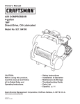
Owner's
Manual
CRRFTSl4Rli°
AiR COMPRESSOR
4-gallon
1HP
Direct-Drive,
Oil-Lubricated
Model No. 921.164780
CAUTION"
Before using this product,
read this manual and follow
all its Safety Rules and
Operating Instructions.
•
•
•
•
•
Safety Instructions
Installation
& Operation
Maintenance & Storage
Troubleshooting
Guide
Parts List
• Espa_ol,
Sears
Brands
Management
www.sears.com/craffsman
11/03/2011
Part No. 101-3368
Corporation,
Hoffman
Estates,
p. 11
IL 60179
U.S.A.
Table of Contents
Page
See Below
Warranty ..............................................................
Safety Symbols
..........................................................
1
Important Safety Instructions & Guidelines .....................................
1
Specifications ............................................................
2
Glossary ................................................................
2
Duty Cycle ..............................................................
2
Parts & Features .........................................................
3
Installation & Assembly
4
Operating Procedures
....................................................
.....................................................
5
Maintenance .............................................................
6
Storage
6
................................................................
Troubleshooting
Guide .....................................................
7
Exploded View ...........................................................
8
Parts List ...............................................................
9
Espadol
................................................................
10
CRAFTSMAN ONE YEAR FULL WARRANTY
FOR ONE YEAR from the date of purchase, this product is warranted against any defects in material or workmanship.
defective product will receive free repair or replacement if repair is unavailable.
For warranty coverage
This warranty
details to receive free repair or replacement,
visit the web site: www.craftsman.com
is void if this product is ever used while providing commercial
services or if rented to another person.
This warranty gives you specific legal rights, and you may also have other rights which vary from state to state.
Sears Brands Management
Corporation,
Hoffman
Estates,
IL 60179 U.S.A.
A
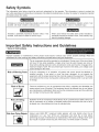
Safety Symbols
The information listed below should be read and understood by the operator. This information is given to protect the
user while operating and storing the air compressor. We utilize the symbols below to allow the reader to recognize important
information about their safety.
Indicates an imminently hazardous situation which, if not
avoided, will result in death or serious injury.
Indicates a potentially hazardous situation which, if not
avoided, may result in minor or moderate injury.
Indicates a potentially hazardous situation which, if not
avoided, could result in death or serious injury
When used without the safety alert symbol indicates a
potentially hazardous situation which, if not avoided, may
result in property damage.
Important
Safety Instructions
and Guidelines
• Save all instructions
Improper operation or maintenance of this product could result in serious injury and/or property damage. Read and
understand all of the warnings and safety instructions provided before using this equipment.
The air compressor should be operated on a dedicated 15 amp circuit. If the circuit does
not have 15 free amps available, a larger circuit must be used. Always use more air
hose before utilizing extension cords. All extension cords used must be 12 gauge with a
maximum length of 25 ft. The circuit fuse type must be a time delay. Low voltage could
cause damage to the motor.
Risk of Moving
Parts
If the air compressor is in operation, all guards and covers should be attached or
installed correctly. If any guard or cover has been damaged, do not operate the
equipment until the proper personnel has correctly repaired the equipment. The power
cord should be free of any moving parts, twisting and/or crimping while in use and while
in storage.
Risk of Burns
There are surfaces on your air compressor that while in operation and thereafter can
cause serious burns if touched. The equipment should be allowed time to cool before
any maintenance is attempted. Items such as the compressor pump and the outlet tube
are normally hot during and after operation.
Risk of Falling
Operation of the air compressor should always be in a position that is stable. Never use
the air compressor on a rooftop or elevated position that could allow the unit to fall or
be tipped over. Use additional air hose for elevated jobs.
Risk from Flying Objects
Always wear ANSI Z87.1 approved safety glasses with side shields when the air
compressor is in use. Turn off the air compressor and drain the air tank before
performing any type of maintenance or disassembly of the hoses or fittings. Never point
any nozzle or sprayer toward any part of the body or at other people or animals.
1
Important Safety Instructions
& Guidelines
Risk of Breathing
_:74o,._,hm!_.,2.,.
Avoid using the air compressor in confined areas. Always have adequate space
(12 inches) on all sides of the air compressor. Also keep children, pets, and others out of
the area of operation. This air compressor does not provide breathable air for anyone or
any auxiliary breathing device. Spraying material will always need to be in another area
away from the air compressor to not allow intake air to damage the air compressor filter.
Risk of
Electrical Shock
Never utilize the air compressor in the rain or wet conditions. Any electrical issues or
repairs should be performed by authorized personnel such as an electrician and should
comply with all national and local electrical codes. The air compressor should also have
the proper three prong grounding plug, correct voltage, and adequate fuse protection.
Risk of
Never operate the compressor near combustible materials, gasoline or solvent vapors.
If spraying flammable materials, locate the air compressor at least 20 feet away from the
spray area. Never operate the air compressor indoors or in a confined area.
Explosion
or Fire
Risk of Bursting
Always drain the air compressor tank daily or after each use. If the tank develops a leak,
then replace the air compressor. Never use the air compressor after a leak has been
found or try to make any modifications to the tank. Never modify the air compressor's
factory settings which control the tank pressure or any other function.
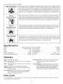
Specifications
Pump ..........................
Motor ............................
Bore .......................................
Stroke ......................................
Oil-lube, direct=drive
1.0 HP (Induction)
1.65"
1.26"
Voltage Single Phase .......................
Minimum Circuit Requirement ................
120 VAC
15 Amps
Air Tank Capacity .........................
Cut-in Pressure .............................
Cut-out Pressure ...........................
SCFM @ 90 PSI ................................
Oil Capacity .........................
Oil Type ........................
4 Gallons
95 PSI
125 PSI
2.4
90 mL or 3 oz.
SAE 30 Non-detergent
Glossary
CFM:
Cubic feet per minute.
SCFM: Standard cubic feet per minute; a unit of measure
for air delivery.
PSlG: Pounds per square inch gauge; a unit of measure
for pressure.
ASME: American Society of Mechanical Engineers.
California Code: Unit may comply with California Code
462 (I) (2)/(M) (2).
Cut-In Pressure: The air compressor will automatically
start to refill the tank when the pressure drops
below the prescribed minimum.
Cut-Out Pressure: The point at which the motor stops
when the tank has reached maximum air
pressure.
Code Certification:
Products that bear one or more of
the following marks: UL, ULc, ETL, CSA, have
been evaluated by OSHA=certified independent
safety laboratories and meet the applicable
Underwriters Laboratories Standards for Safety.
Duty Cycle
This is a 50% duty cycle air compressor.
could damage the air compressor.
Do not run the air compressor more than 30 minutes of one hour. Doing so
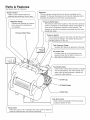
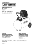
Parts & Features
See figures below for reference.
Quick Connect
Offers a quick release feature for
attaching and removing the air hose.
The air pressure coming from the air tank is controlled by the
regulator. To increase the pressure turn the knob clockwise and to 1
Regulator
decrease the pressure turn the knob counterclockwise.
Pressure Relief Valve
"/
/
Indicates the outgoing air pressure I
'_ Regulator
to the toolGauge
and is controlled by
|"]
J
the regulator.
Pressure
The pressure relief valve located on the side of the pressure|
switch, is designed to automatically release compressed air l
when the air compressor reaches cut-out pressure. The
|
released air should only escape momentarily and the valve |
should then close.
J
Relief Tube
Pressure
Switch
This controls the power to the motor and also the cut-in/
cut-out pressure settings. This switch serves as the
AutolOff positions for the unit.
Tank Pressure Gauge
Indicates the reserve air pressure in the tank.
Air Intake Filter
Provides clean air to the pump and must
always be kept free of debris. Check on a
daily basis or before each use.
Tank Safety Valve
Used to allow excess tank pressure to escape
into the atmosphere. This valve should only
open when the tank pressure is above the
maximum rated pressure.
Oil Fill Cap
Oil Sight Gauge
Outlet Tube
Tank Drain Valve
Used to drain condensation from the air tank.
Located at bottom of tank.
I
When the pump is not in operation the valve closes to retain air
Check Valve
1
pressure inside the tank. An internal component.
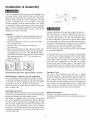
Installation & Assembly
The air compressor should be turned off, unplugged from
the power source, the air bled from the tank and the unit
allowed time to cool before any maintenance is performed.
Personal injuries could occur from moving parts, electrical
sources, compressed air or hot surfaces. The quick
connect assembly must be attached before use. Failure
to assemble correctly could result in leaks and possible
injury. If unsure of assembly instructions or you experience
difficulty in the assembly please call your local service
department for further instruction.
Assembly
1. Remove air compressor, handle assembly, hardware,
oil bottle, intake filter, manual and accessories from
the styrofoam.
2. Remove the plastic plug from the compressor intake
port. (see diagram below)
3. Install the filter in the compressor intake port.
(see diagram below)
4. Remove the oil fill cap from the crankcase and fill until
the oil reaches the top of the red dot in the sight glass.
Oil capacity is 3 oz. (seebelow)Use SAE-30 non-deter
gent (API CG/CD heavy duty motor oil). Under extreme
cold weather conditions, 32 ° F (0°C) or below, use
SAE-10 weight oil.
5. Replace the oil cap.
Estimated
Assembly Time: Approximately
2 minutes
Getting Started = Location of the Air Compressor
The air compressor should always be located in a clean,
dry and well ventilated environment. The unit should have
at minimum, 12 inches of space on each side. The air filter
intake should be free of any debris or obstructions.
Check the air filter on a daily basis to make sure it is clean
and in working order.
Grounding Instructions
This product should be grounded. In the event of an electrical
short circuit, grounding reduces the risk of electric shock by
providing an escape wire for the electric current.
This product is equipped with a cord having a grounding
wire with an appropriate grounding plug. (See the figure at
top right corner.) The plug must be plugged into an outlet
that is properly installed and grounded in accordance with
all local codes and ordinances. Check with a qualified
electrician or service personnel if these instructions are not
completely understood or if in doubt as to whether the tool
is properly grounded.
Grounded
Outlet
Grounding
Pin
Improper installation of the grounding plug will result in a
risk of electric shock. If repair or replacement of the cord
or plug is necessary, do not connect the grounding wire to
either flat blade terminal. The wire with insulation having
an outer surface that is green with or without yellow stripes
is the grounding wire. Check with a qualified electrician or
serviceman if the grounding instructions are not completely
understood, or if in doubt as to whether the product is
properly grounded. Do not modify the plug provided.
If it will not fit the outlet, have the proper outlet installed
by a qualified electrician.
This product is for use on a circuit having a nominal rating
of 120 volts and is factory-equipped with a specific electric
cord and plug to permit connection to a proper electric
circuit. Make sure the product is connected to an outlet
having the same configuration as the plug. An adapter
should not be used with this product. If the product must
be reconnected for use on a different type of electric circuit,
qualified service personnel should make the reconnection.
Extension Cords
Use only a 3-wire extension cord that has a 3-blade
grounding plug and a 3-slot receptacle that will accept the
plug on the product. Make sure your extension cord is in
good condition. When using an extension cord, be sure to
use one heavy enough to carry the current your product will
draw. Cords must not exceed 25 feet and No. 12 AWG size
must be used. An undersized cord will cause a drop in line
voltage resulting in loss of power and overheating.
Break In Procedures
No break in procedure is required by the user.
This product is factory tested to ensure proper operation and
performance.
Operating Procedures
Daily Start-Up Procedures
1. Set the Auto/Off lever to the Off position.
2. inspect the air compressor, air hose, and any
accessories/tools being used for damage or obstruction.
If any of these mentioned items are in need of repair/
replacement, contact your local authorized service dealer
before use.
3. Close the drain valve.
4. Check the oil level of the pump.
5. Connect the air hose to the quick connect socket on
the regulator assembly by inserting the quick connect
plug on the air hose into the quick connect socket. The
quick connect socket collar will snap forward and lock
the plug into place providing an air tight seal between
the socket and plug. To release the air hose push the
collar back on the quick connect socket.
6. Plug the power cord into the proper receptacle.
7. Turn the Auto/Off lever to the Auto position and the
compressor will start and build air pressure in the
tank to cut-out pressure and then shut off automatically.
8. Adjust the regulator to a PSi setting that is needed for
your application and be sure it is within the safety
standards required to perform the task. If using a
pneumatic tool, the manufacturer should have
recommendations in the manual for that particular
tool on operating PSi settings.
9. The air compressor is now ready for use. The following
inflation and cleaning accessories packaged with this
unit should only be operated at maximum pressure
of 90PSI: blow gun, rubber-tapered nozzle, inflation
needles, adapter, and blow gun adapter.
®
Daily Shut-Down Procedures
1. Set the Auto/Off lever to the Off position.
2. Unplug the power cord from the receptacle.
3. Set the outlet pressure to zero on the regulator.
4. Remove any air tools or accessories. When draining
the tank, always use ear and eye protection. Drain the
tank in a suitable location; condensation will be present
in most cases of draining.
5. Open the drain valve allowing air to bleed from the
tank. After all of the air has bled from the tank, close
the drain valve to prevent debris buildup in the valve.
CLOSED
_
OPEN
When draining the tank, always use ear and eye protection.
Drain the tank in a suitable location; condensation will be
present in most cases of draining.
Water that remains in the tank during storage will corrode
and weaken the air tank which could cause the tank to
rupture. To avoid serious injury, be sure to drain the tank
after each use or daily.
Maintenance
NOTE:
Any service procedure not covered in the
maintenance schedule should be performed by
qualified service personnel.
The air compressor should be turned off, unplugged
from the power source, air bled from the tank and
allowed time to cool before any maintenance is
performed.
Before each use
or daily
items to Check/Change
Check Tank Safety Valve
X
Overall Unit Visual Check
X
Check Air Filter
X
Drain Tank
X
X
i Check Power Cord for Damage
after first 50 hours
Check the safety valve by performing these three steps:
1. Plug the compressor in and run until shut-off
pressure is reached.
2. Wearing safety glasses, pull out on the safety valve
ring to release pressure from the tank.
3. The safety valve should close automatically at
approximately at 40-50 PSI. If the safety valve does not
allow air to be released when you pull out on the ring, or
does not close automatically, it must be replaced.
Do not attempt to remove or adjust the safety valve.
From time to time, the air filter needs to be removed and
cleaned.
1. Turn the air compressor off.
2. Unplug the air compressor.
3. Turn the air filter cover counterclockwise to remove.
4. Remove air filter from air filter housing.
5. Blow compressed air through the air filter for
10-15 seconds.
Change Oil
after every 100 hours
i Check Oil Level
X
NOTE: The motor will automatically restart without
warning if the unit is left plugged in to an outlet with the
Auto/Off switch in the on position.
To ensure efficient operation and longer life of the
air compressor unit, a routine maintenance schedule
should be followed. The following schedule is geared
toward a consumer whose compressor is used in a
normal working environment on a daily basis.
This compressor is equipped with an automatic reset
thermal overload protector which will shut off motor if it
becomes overheated. If the thermal overload protector
is actuated, the motor must be allowed to cool down
before start-up is possible.
For more details, see Troubleshooting
Guide (page 7).
Storage
For storing the air compressor, be sure to do the following:
1. Turn the unit off and unplug the power cord from the
receptacle.
2. Remove all air hoses, accessories, and air tools from
the air compressor.
3. Perform the daily maintenance schedule.
4. Open the drain valve to bleed all air from the tank.
5. Close the drain valve.
6. Store the air compressor in a clean and dry location.
Troubleshooting
Guide
The air compressor should be turned off and unplugged from the power source before any
maintenance is performed as well as the air bled from the tank and the unit allowed time to cool.
Personal injuries could occur from moving parts, electrical sources, compressed air, or hot surfaces.
PROBLEM
POSSIBLE
CORRECTION
Air leaks at the check valve
A defective check valve results in a constant air leak at the pressure relief valve
or at the pressure relief valve.
when there is pressure in the tank and the compressor
is shut off. Drain the tank,
then remove and clean or replace the check valve.
Air leaks between head and
Be sure of proper torque on head bolts. If leak remains, contact a service technician.
cylinder.
Air leak from safety valve.
Operate the safety valve manually by pulling on the ring. If the valve continues to
leak when in the closed position, it should be replaced.
Pressure reading on the
If there is an excessive
regulated pressure gauge
replace the regulator.
amount of pressure drop when the accessory
is used,
drops when an accessory is
used.
Adjust the regulated pressure under flow conditions (while accessory is being used).
It is normal for the gauge to show minimal pressure loss during initial use of the
tool.
Excessive tank pressure.
Move the Auto/Off lever to the Off position. If the unit doesn't shut off,
unplug it from the power source and contact a service technician.
Motor will not start.
Make sure power cord is plugged in and the switch is on. Inspect for the proper size
fuse in your circuit box. If the fuse was tripped, reset it and restart the unit. If
repeated tripping occurs, replace the check valve or contact a service technician.
Excessive moisture in the
Remove
discharge air.
environments
the
water
in the tank
will cause excessive
by draining
after
condensation.
each
use.
High
humidity
Utilize water filters on your air
line.
m
Water
condensation
compressor's
air
is not caused
output
is greater
by compressor
than
your
malfunction.
tool's
air
Be sure
consumption
the
rate.
Air leaks from the tank body
Never drill into, weld or otherwise modify the air tank or it will weaken. The tank can
or tank welds.
rupture or explode. Compressor
compressor.
cannot be repaired.
Discontinue
use of the air
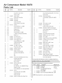
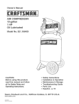
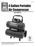
Air Compressor
Parts List
Model 16478
15_
/
20-- /
57_\
\
/
_51
/
49_
\
745
32-33 --,
_,
44
/'
37 -/
Air Compressor
Parts List
Part No.
No.
L Ref.
Model 16478
Description
Quantity
No.
Kit
Ref.
No.
Kit Part No.
No.
Description
Quantity J
1
3
Screw,M6X 1.0ramX 30ram
4
42
Screw,Hex FlangeHead,M8 x 1.25x 50 mm 3
2
3
Washer,LockM6
8
43
Washer,FlatM8
3
3
1
44
4
1&3
1
45
Tank Assembly,4 gallonSS L14SHPS
5
3
E100228 Plate,Valve
2
46
N/A
6
3
E100229 Valve Reed
2
47
N/A
7
1&3
Gasket,Valve Plate
1
48
N/A
8
1&3
Gasket,Cylinderto Valve Plate
1
49
E101208 Valve,Check,Top Port
9
2&3
1
50
E105419 Hose, SS Braid 11"
10
3
11
E100227 Head,Cylinder
Gasket,HeadtoValvePlate
E101113 Cylinder
3
E101346 Plate,MotorMounting
1
1
1
Screw,SHC M6 x 1.0 x 20MM
4
1&3
Gasket,Cylinder,Lower
1
51
12
2&3
Eccentricfor L1
1
52
5
Tube, PressureRelief1/4"Cu 10.8"long
1
13
2&3
Nut, Hex,M6xl.0
1
53
5
Nut, Comp,1/4"
2
14
2&3
Screw,SHCM6x 1.0x 20MM
1
54
5
Ferrule,1/4"
2
15
2&3
L1 Piston/ConnectingRod Assembly
1
55
E100736 Assy,Switch, Pressure(125 PSI)
1
16
1&3
Bafflefor L1
1
56
E100594 Restraint,Powercord - 14/3SJT
2
17
3
E100087 Cap,OilFillw/o-ring
1
57
E102595 Valve,Safety
1
18
3
E100566 Cover,Crankcasefor L1
1
58
E103339 Gauge,Pressure,(38mmw/125 PSI R/L)
1
19
3
E100078 Plug,oil sight w/seal
1
59
E102934 Coupling,3 port Tee 1/4 FNPT
1
20
3
21
3
22
3
23
3
24
3
25
3
26
3
Washer,ToothLock, 8mm
27
3
Nut,M8x1.25,ZDC6.5MMTALL
Screw,HFHM5 x 0.8 x 15MM
Ig 3/8 fm Compx 3/8 fm comp
60
61
E100724 Nipple,Steel 1/4 NPT x 50mm
1
62
E105294 Gauge,Pressure,
(50mm 125PSI R/L, 1/8" NPT)
1
1
63
E101350 Nipple,Steel 1/4 NPT x 75mm
1
E100247 Capacitor,Running
1
64
E100210 Regulator,RndBdy,Blkknob,
E100248 Capacitor,
Starting
1
E100860 Fan, MotorF1 125mm
Ring,Snap, Outer,15mm
1
2
65
E100307 QuickConnect,Brass
1
66
E101717 Valve,Drain 1/4 Turn
1
E105129 Badge,CraftsmanL14SHPS
1
68
4
33
4
34
4
1
Assembly,Motor/Pump,
L1B2w/LH Exhaust
1
Base,Air Filter
1
E100435 Element,IntakeFilter
1
Cover,Filter
1
35
Bolt, SHC M8 x 1.25x 25MM(ZDC Plate)
4
36
Washer,Lock, M8
7
37
Screw,HFPHM5 x 0.8 x lOmm (ZDC Plate)
6
38
39
40
41
E101137 Shroud
1
Screw,SHC, M8 X 1.25X 20MM
(YellowZinc Dich)
4
Washer,Flat,M8
4
E100240 Isolator,Foot (60mmDia X 28mmTall)
1
11
67
E100101 Cord,Power 14/3AWGtype SJT6' long
2
1/8 NPTguageportRHFlow
N/A
32
1
4
29
3
Plug, 1/4"NPT
1
Motor/Pump,
L1B2
N/A
31
E100809 Fitting,Elbow,3/8NPTx 3/8Compression
(YellowZinc Dich Plate)
28
30
1
4
Screw,#8SemsOval Headwith CSKWasher,
4mm x 20mm,BlackZn
4
Note:Anypart/kitnumberfieldwithouta numberis notavailable.Descriptions
are
providedforreference
only. TheKit#columnrepresents
thatthe partbeingofferedis
availableina kit.Oneof eachpartperkitwillbe offered.
Kit numberand parts that are includedare as follows:
Kit No. Part No.
Description
1
E100959 Kit, Gasket
2
E100251 Kit, Piston*
E105222 Kit, L1B2Motor/PumpAssy.
3
w/LH Exhaust
4
E100794 Kit, Air Filter
5
E105223 Kit, 1/4"Cu PressureReliefTube
* NOTE:OrderGasketKit #1, as well, when orderingthis kit
ReferenceNo.
4,7,8, 11, 16
9,12-15
1 - 27, 31
32-34
52-54
Manual de
CRRFTSMRll°
COMPRESOR
15.1 LITROS
1HP
DE AIRE
De impulsi6n directa,
iubricada con aceite
# de Modelo 921.164780
PRECAUCION:
Antes de usar
el producto, lea este manual
sus reglas e instrucciones
de seguridad.
Sears
Brands
Management
www.sears.com/craftsrnan
11/03/2011
Part No. 101-3368
y siga
Corporation,
• Instrucciones y pautas de
seguridad
importantes
• Instalaci6n y operacion
• Mantenimiento y AImacenamiento
• Diagnostico
y correccion
de fallas
• Lista de las piezas
Hoffman
Estates,
IL 60179
U.S.A.
Contenido
P_gina
Garanfia ................................................................
12
Simbolos de seguridad .....................................................
13
Instrucciones y pautas de seguridad importantes ................................
13
Especificaciones ..........................................................
14
Glosario ................................................................
14
Ciclo de trabajo
14
..........................................................
Partes y caractedsticas
....................................................
15
Instalaci6n y ensamblaje ...................................................
16
Procedimientos
de operaci6n ................................................
17
Mantenimiento
...........................................................
18
Almacenamiento
..........................................................
18
Diagn6stico y correcci6n de fallas ............................................
19
Lista de partes .......................................................
20
GAFIANTiA
UN AKIO DE GAFIANTiA DE GANATiA
DURANTE
fabricaci6n.
possible,
DE CRAFTSMAN
UN ANO desde la fecha de compra, este producto tiene garantia contra defectos en los materiales o en la
Los productos defectuosos
se repararan gratuitamente
o se reemplazaran
sin coste si la reparaci6n no es
Para conocer los detalles de cobertura de la garantia con el fin de obtener una reparaci6n o un reemplazo,
web www.oraftsman.oom
Esta garantia no es valida si el producto se utiliza para proporcionar
Esta garantia le proporciona
del pais o el estado.
derechos
Sears Brands
legales especificos
Management
servicios comerciales
visite el sitio
o si se alquila a un tercero.
y es posible que ademas tenga otros derechos, dependiendo
Corporation,
12
Hoffman
Estates, IL 60179 EE. UU.
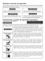
Simboios comunes de seguridad
El operador debe leer y entender la informaci6n descrita a continuaci6n. Esta informaci6n se ofrece para proteger al
usuario al operar y almacenar el compresor de aire. Los simbolos siguientes son los que se utilizan para indicar al lector
informaci6n que es importante para su seguridad.
Indica una situaci6n de riesgo inminente que, al no
protegerse, provocar_ lesiones graves o la muerte.
Indica una situaci6n potencialmente petigrosa que, de no
evitarse, podria provocar lesiones menores o moderadas.
Indica una situaci6n potencialmente peligrosa que, al no
protegerse, podria provocar lesiones graves o la muerte.
Cuando no aparezca sin et simbolo de alerta de seguridad, 6sto
quiere decir que hay una situaci6n potencialmente petigrosa
que, al no protegerse, podria causar da_os materiales.
Instrucciones
• Guarde todas
y pautas de seguridad importantes
las instrucciones
•
La operaci6n y el mantenimiento inadecuados de este producto pueden provocar lesiones graves y dados materiales.
Antes de utilizar este equipo, lea y entienda las advertencias e instrucciones de seguridad aqu[ contenidas.
El compresor de aire se debe operar desde un circuito especial de 15 amperios.
Si et circuito no dispone de una capacidad de 15 amperios, se debe usar un circuito
de mayor capacidad. Si es necesario, antes de emplear una extensi6n el6ctrica, adada
una manguera de aire m_s larga. Las extensiones et6ctricas deben set de calibre 12
y tener una longitud maxima de 7,6 metros. El fusible del circuito debe ser de acci6n
retardada. Un voltaje demasiado bajo puede dadar et motor.
Riesgo pot partes en
movirniento
Riesgo de quemacluras
Riesgo
de caida
Riesgo de lanzamiento
de objetos
AI operar
el compresor, todos los protectores y cubiertas deben estar fijados e
instalados correctamente. Si alguno de los protectores o cubiertas est_ da_ado, no
opere el equipo hasta que personal calificado repare el problema. El cable de corriente
debe mantenerse alejado de las partes m6viles del equipo y no debe torcerse ni
prensarse durante su empleo, ni al almacenarse.
En su compresor hay superficies que, al ser tocadas durante y despu6s de su
operaci6n, pueden causar quemaduras graves. Antes de darle mantenimiento al
equipo, se debe dejar enfriar. Por Io normal, durante y despu6s de su operaci6n,
ciertas partes como la bomba del compresor y el tubo de salida estar_n calientes.
El compresor siempre debe ser operado en una posici6n estable. Nunca utilice el
compresor sobre un techo o en una posici6n elevada ya que podda caer o
volcarse. AI trabajar en posiciones elevadas, utilice una manguera de aire m_s larga.
AI emplear el compresor, siempre utilice anteojos de seguridad con protectores
laterales que cumplan con la norma ANSI Z87.1. Antes de Ilevar a cabo cualquier clase
de mantenimiento y antes de desconectar las mangueras y los acopladores, apague
el compresor y drene el tanque de aire. Nunca apunte la boquilla o el rociador hacia
ninguna parte de su cuerpo, ni 61 de otros seres.
13
lnstrucciones
y pautas de seguridad importantes
Evite utilizar el compresor de aire en _reas encerradas. Siempre tenga un espacio
libre adecuado (30 cm.) en todos los lados del compresor. Tambi6n mantenga fuera
del _rea de operaci6n alas mascotas, nifios y otras personas. Este compresor de aire
no provee aire que pueda ser respirado ni empleado con un dispositivo respiratorio
auxiliar. El material de rociado siempre deber_ estar en otra zona, alejado del compresor
de aire, para evitar que el aire aspirado dafie al filtro del compresor.
Riesgo para la
respiraci6n
Riesgo de
descargas
el6ctricas
Nunca utilice el compresor de aire bajo Iluvia o en lugares mojados. Los problemas
el6ctricos deben set reparados por personal autorizado, tal como seda un electricista,
y deben cumplir con las normas el6ctricas nacionales y locales. El compresor tambi6n
debe tenet la clavija apropiada de tres terminales para hacer tierra y contar con
un suministro el6ctrico que sea del voltaje correcto y con un fusible de protecci6n
adecuado.
Riesgo de
explosi6n y fuego
Nunca opere el compresor cerca de materiales combustibles, gasolina ni vapores
de solventes. Si est_ rociando materiales inflamables, coloque el compresor a una
distancia de cuando menos 6 metros del _rea de rociado. Nunca opere el compresor
de aire en interiores o en lugares cerrados.
Riesgo de estallido
Drene el compresor diariamente o despu6s de cada utilizaci6n. Si el tanque tiene una
fuga, reemplace el compresor. Nunca utilice el compresor si se ha detectado una fuga,
ni trate de modificar el tanque. Nunca modifique los ajustes de f_brica del compresor
que controlan la presi6n del tanque y demos funciones.
Especificaciones
Bomba ............................
De impulsi6n
directa, lubricada con aceite
Motor ...........................
Di_metro .................................
Carrera ..................................
Capacidad del tanque de aire ...............
15.1 litros
Presi6n de arranque ...............
655.0 KPa / 95 PSI
Presi6n de parada ................
861.8 KPa / 125 PSI
PiescQbic0sp0r minut0(SCFM)a 90 LPPC......................
2.4
1.0 HP (Inducci6n)
41.9 mm
32.0 mm
Voltaje monof_sico .........................
Capacidad minima del circuito ....................
Capacidad del aceite ................
120 VAC
Tipo de aceite ..................
15 A
90 ml o 3 onzas.
SAE 30 - no detergente
Glosario
CFM:
Pies c_bicos por minuto.
Presi6n
de arranque: El compresor arranca
autom_ticamente cuando la presi6n baja a menos
del minimo prescrito.
Presi6n de parada: El motor se para cuando el tanque
alcance la presi6n m_xima de aire.
Certificaci6n
de c6digo:
Los productos que tienen
alguna o varias de las siguientes marcas han sido
evaluados
pot
laboratorios
de
seguridad
independientes certificados por OSHA, y cumplen
con las normas de seguridad de Underwriters
Laboratories: UL, , ETL, CSA.
SCFM: Pies cQbicos est_ndar pot minuto; unidad de
medici6n de suministro del aire.
PSIG: Libras por pulgada cuadrada sobre la presi6n
atmosf6rica; unidad de medici6n de presi6n.
ASME: Sociedad estadounidense de ingenieros mec_nicos.
C6digo de California: La unidad puede cumplir con el
c6digo de California 462 (I) (2)/(M) (2).
Ciclo de trabajo
Este compresor tiene un ciclo de trabajo de 50%. Nunca opere el compresor por m_s de 30 minutos cada hora.
Ya que al hacerlo, podda dafiarlo.
14
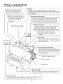
Partes y caracteristicas
Como referencia, yea las figuras abajo.
Permite conectar y desconectar
I Conector de acoplamiento
r_pido
r_pidamente la manguera del aire.
Indica la presi6n de salida del aire I
que entra en la herramienta, la |
Man6metro
presi6n de
cual que esdecontrolada
porsalida "_
|
el regulador.
J
I
La presi6n del aire que sale del tanque es controlada por el
|
regulador. Para aumentar la presi6n, gire la perilla en direcci6n de |
Regulador
las manecillas; para disminuirla, gire la perilla en direcci6n contraria "_I
alas manecillas.
,J
Valvula de alivio de presi6n
Esta v&lvula, que se encuentra en el costado del interruptor
de presi6n, est& disefiada para liberar aire comprimido
de manera autom_tica cuando el compresor Ilegue a la
presi6n de parada. El aire s61o deber_ escapar durante
un instante, cerr_ndose la v_lvula se cerrar_ en seguida.
Interruptor de presi6n
fl
Controla el suministro el@trico en el motor y tambi@
los ajustes de presi6n de arranque y presi6n de
parada. Este interruptor sirve como posici6n de
autoencendido V apaqado (Auto-On/Off) de la unidad.
J
Tubo de alivio de presi6n
Man6metro de presi6n del tanque
Indica la presi6n de la reserva de aire
del tanque.
Filtro del aire
Suministra aire limpio a la bomba. Siempre
debe conservarlo limpio. Reviselo diariamente
o antes de cada uso.
V_lvula de seguridad del tanque
Permite que el exceso de presi6n en el
tanque escape hacia el medio ambiente. Esta
v_lvula s61o se abrir_ cuando la presi6n en el
tanque est6 por encima de la presi6n m_xima
nominal del modelo.
Tap6n de lienado de aceite
Visor de aceite
Outlet Tube
_ Valvula de drenaje
\
v_lvula
']
Sirve para drenar la condensaci6n acumulada en el fondo /
del tanque . s e encuentra en !a pa_e inferi°r de! tanque:
1)
de retenci6n
"}
Cuando la bomba no est_ en operaci6n, esta v_lvula se cierra para retene
la presi6n de aire dentro del tanque. Es un componente interno.
15
Instalaci6n y ensamblaje
con terminal de tierra (ver la figura a continuaci6n). La
clavija debe enchufarse en un tomacorriente instalado y
puesto a tierra segQn las normas locales. Hable con un
electricista o agente de servicio calificado si no entiende
completamente
estas instrucciones,
o si tiene dudas
sobre la correcta puesta a tierra de la herramienta.
Antes de darle cualquier tipo de mantenimiento
al
compresor de aire, se debe apagar y desconectar de la
fuente de alimentaci6n el6ctrica, adem_s de purgar el aire
del tanque y darle suficiente tiempo para enfriarse. Existe
el riesgo de que las partes m6viles, las fuentes el6ctricas,
el aire comprimido y las superficies calientes provoquen
lesiones. El ensamblaje de conexi6n r_pida debe estar
instalado antes de usar el compresor. Un ensamblaje
inadecuado puede ser causa de fugas y posiblemente de
lesiones. Si no est_ seguro de entender las instrucciones
de ensamblaje o tiene dificultad para Ilevar a cabo el
armado, por favor Ilame a su departamento local de
servicio para obtener m_s instrucciones.
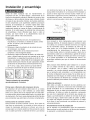
Cla vija
Terminal de tierra
Una conexi6n a tierra inadecuada puede provocar una
descarga el6ctrica. Si necesita reparar o cambiar el cable
o la clavija, no conecte el alambre de tierra con ninguna
de las terminales planas. El alambre de tierra es de
color verde, con o sin franjas amarillas. Si no entiende
completamente las instrucciones de conexi6n a tierra,
o si tiene dudas sobre la correcta puesta a tierra de la
herramienta, hable con un electricista o agente de servicio
calificado. No modifique la clavija que viene con el equipo;
si no puede enchufarla en el tomacorriente, Ilame a un
electricista calificado para que le instale el tomacorriente
adecuado.
Este producto est_ disefiado para trabajar en un circuito
con un voltaje nominal de 120 voltios y est& equipado
en la f_brica
con un cable y clavija que permiten su
conexi6n a un circuito el6ctrico apropiado. AsegQrese de
que el producto est6 conectado a un tomacorriente con
la misma configuraci6n que la clavija. No se debe usar un
adaptador con este equipo. Si debe conectar el equipo con
un circuito el6ctrico de diferente tipo, consiga la ayuda de
personal calificado para realizar la reconexi6n.
32 ° F (0°C) o bajo, utilice aceite muy fluido SAE-10.
5. Coloque nuevamente el tap6n de Ilenado de aceite.
!!LJ
de ensamblaje:
5 minutos
Cables de extensi6n
$61o utilice un cable de extensi6n de tres alambres con
una clavija con extensi6n a tierra de tres terminales que
pueda enchufarse en un tomacorriente de tres orificios.
Asegt3rese de que su cable de extensi6n est6 en buenas
condiciones. Si utiliza un cable de extensi6n, compruebe
que sea de la capacidad de la corriente que requiere su
equipo. Las extensiones no deben ser de m_s de 25 pies
(7,6 m) de largo y deben tener cable de calibre 12 AWG.
Un cable m_s delgado provocar_ una caida en el voltaje
de la linea, Io que provocada una p6rdida de potencia y
sobrecalentamiento.
Primer paso: Ubicaci6n del compresor del aire
El compresor dei aire siempre debe estar en un medio
ambiente limpio, seco y bien ventilado. La unidad debe
tener por Io menos 30 cm de espacio libre en cada lado.
La toma del filtro del aire debe estar limpia y sin ningQn tipo
de obstrucci6n. Pot favor revise diariamente el filtro del aire
para comprobar que est6 limpio y funcione correctamente.
Instrucciones
de conexi6n
.-J
Tomacorrientes
con conexi6n a
tierra
Ensamblaje
1. Remueva el compresor de aire, el ensamble de la
empufiadura, la ferreteda, la botella de aceite, el filtro
de aire, el manual y los accesorios de la
empaquetadura.
2. Remueva el tap6n de pl_stico de la entrada de aire
del compresor. (vet abajo)
3. Instale el filtro dentro de la entrada de aire del
compresor. (vea el diagrama abajo)
4. Remueva el tap6n de Ilenado de aceite, del c_rter del
motor y 116nelohasta el punto rojo marcado en el vidrio
transparente. La capacidad de aceite es de 90 ml - 3
onzas (vea abajo). Utilice SAE-30 sin detergente (API
CG/CD aceite para motores de gran capacidad). Sobre
condiciones de temperaturas extremosamente fdas,
Tiempo estimado
aproximadamente
.._
_t_
a tierra
Este producto se debe conectar a tierra. En el caso de
que haya un cortocircuito, la conexi6n a tierra reduce el
riesgo de descargas el6ctricas al ofrecer una ruta de
escape para la corriente el6ctrica. Este producto cuenta
con un cable que tiene un alambre de tierra y una clavija
Procedimiento
inicial de preparaci6n
No se requiere un procedimiento inicial de preparacidn.
Este producto ha sido probado en la f_brica para asegurar
su operaci6n y rendimiento adecuados.
16
Proced imientos de operaci6n
Procedimiento diario de arranque
1. Ponga el interruptor Auto/Off en la posici6n de
apagado (Off).
2. Vedfique que el compresor deJ aire, la manguera de
aire y todos los accesorios/herramientas utilizados, no
tengan da_os ni obstrucci6n. Si algunas de las piezas
descdtas requieren raparaci6n/reemplazo,
Ilame a su
tienda autorizada local de servicio, antes de usar el
compresor.
3. Cierre la v&lvula de drenaje.
4. Revise el nivel de aceite de la bomba.
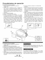
5. Enchufe la manguera del aire dentro del conector
de acoplamiento r&pido de la unidad del regulador,
insertando la clavija de conexi6n r&pida en la manguera
del aire, dentro del conector de acoplamiento r&pido.
El collarin del conector de acoplamiento r&pido sattar&
hacia adelante, sujetando la davija y har& una junta
entre el conector y la clavija. Para desconectar la
manguera del aire, empuje hacia atr&s el colladn del
conector de acoplamiento r&pido.
6. Enchufe el cable de corriente en un tomacorriente
apropiado.
7. Mueva el interruptor Auto/Off a la posici6n de encendido
(Auto); el compresor deber& arrancar, acumulando la
presi6n del aire en el tanque hasta Ilegar a la presi6n
de apagado, momento en el cual se apagar& de manera
autom&tica.
, Ajuste
el regulador a la presi6n de aire recomendada
(PSI) para su aplicaci6n, cercior&ndose de que est6
dentro de las normas de seguridad para Ilevar a cabo
la tarea. Para las herramientas neum&ticas, el manual
del fabricante debe tenet recomendaciones sobre su
presi6n de operaci6n (PSI).
° Ahora
el compresor del aire est& listo para ser usado.
Los siguientes accesorios de inflado y de Iimpieza, los
cuales vienen con esta unidad, s61o se deben operar a
una presi6n m&xima de 90 PSh soplete, boquilla c6nica
de caucho, agujas para inflar, adaptador y adaptador de
soplete.
®
Procedimiento diario de apagado
1. Ponga el interruptor Auto/Off en la posici6n de
apagado (Off).
2. Desconecte el cable del tomacorriente.
3. Ponga en cero el regulador de presi6n de salida.
4. Desconecte las herramientas y los accesorios. Siempre
use protecci6n para los oidos y los ojos al drenar el
tanque. Drene el tanque en un lugar adecuado; en casi
todos los casos habr& presencia de condensaci6n en el
drenaje.
5. Abra la v&lvula de drenaje permitiendo que escape el
aire del tanque. Cuando haya salido del tanque todo el
aire, cierre la v&lvula de drenaje para evitar que entre
suciedad.
AI drenar el tanque utilice protecci6n para oidos y ojos.
Drene el tanque en un lugar apropiado; en la mayoria de
las ocasiones al drenar saldr& condensaci6n.
Si no drena el tanque al almacenarlo, en su interior
quedar& agua que Io corroer& y debilitar&, Io cual puede
provocar su ruptura. Para evitar lesiones graves, drene el
tanque diariamente o despu6s de cada uso.
ABRA
17
Mantenimiento
NOTA: Cualquier procedimiento de servicio que no est6
Asuntos
cubierto en el programa de mantenimiento que sigue deber_
set efectuado el personal de servicio calificado.
para verificadcambiar
Antes de cada uso
o diariarnente
Revisar la v_lvula de seguridad del
tanque
X
Antes de dar mantenimiento al equipo, se debe apagar
y desconectar del tomacorriente, asi como purgar el aire
del tanque y permitir que la unidad se enfde.
Revisar visualmente el aspecto
general de la unidad
X
Revisar el filtro de aire
X
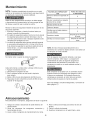
Revisar la v_lvula de seguridad mediante la ejecuci6n de los
tres pasos siguientes:
1. Enchufar el compresor y hacerlo funcionar hasta que
alcance la presidn de desconexi6n.
2. Con gafas de seguridad puestas, tirar del aro de la v_lvula
de seguridad para aliviar la presidn del tanque. Usar la
otra mano para desviar el aire o despojos expelidos a alta
velocidad para protegerse la cara.
3. La v_lvula de seguridad debe cerrarse autom_ti camente
a una presi6n aproximada de 2.8 a 3.4 bar (40 a 50 psi).
Si la v_lvula de seguridad no permite la salida del aire al
tirarse del aro, o no cierra autom_ticamente, es
preciso reemplazarla.
Drenar el tanque
X
Verificar que el cable el6ctrico
no est6 dadado
X
No intentar retirar o ajustar la v_lvula de seguridad.
A fin de asegurar una operaci6n eficiente y una larga
vida del compresor, debe seguir un programa de
mantenimiento de rutina. El siguiente programa de
mantenimiento est_ enfocado al consumidor cuyo
compresor es usado en un medio ambiente normal y
diariamente.
Cambiar el aceite
Verificar el nivel del aceite
Despu6s de tas primeras
50 horas
Despu6s de cada 100
horas
NOTA: El motor reiniciar_ autom_ticamente sin la
advertencia si la unidad es dejada conect6 a una salida con
el interruptor de en/de prendido.
Cada cierto tiempo, se debe retirar y limpiar el filtro de aire.
1. Apague el compresor de aire.
2. Desconecte el compresor de aire.
3. Gire la cubierta del filtro de aire hacia la izquierda
para retirarla.
4. Retire el filtro de aire del alojamiento del filtro de aire.
5. Haga pasar el aire comprimido a trav6s del filtro de aire
durante 10-15 segundos.
Este compresor es equipado con un autom_tico repone
protector t6rmico de sobrecarga que apagar_ el motor
si Ilega a ser recalentado. Si el protector t6rmico de
sobrecarga es accionado, el motor debe ser permitido
enfriarse antes de puesta en marcha es posible.
Para mas detalles, consulte la Diagn6stico y correcci6n de
fallas (p_gina 17).
Aimacenamiento
Para almacenar el compresor, asegt3rese de hacer Io siguiente:
1. Apague la unidad y desconecte el cable el6ctrico del
tomacorriente.
2. Quite del compresor
herramientas de aire.
las mangueras,
accesorios
4. Abra la v_lvula de drenaje para drenar el aire del
tanque.
5. Cierre la v_lvula de drenaje.
6. Guarde el compresor en un lugar limpio y seco.
y
3. Lleve a cabo el programa de mantenimiento de rutina.
18
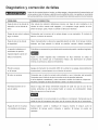
Diagn6stico y correcci6n de fallas
Antes de dar mantenimiento al equipo, se debe apagar y desconectar del tomacorriente, asi
como purgar el aire del tanque y permitir que la unidad se enfde. Las partes en movimiento,
las fuentes el6ctricas, el aire comprimido y las superficies calientes pueden provocar lesiones.
PROBLEMA
POSiBLE CORRECCION
Fuga de aire en la v_lvula de
retenci6n o en la v_lvula de
Una v_lvula de retenci6n defectuosa
alivio.
Drene el tanque, quite y limpie o cambie la v_lvula de retenci6n.
Fugas de aire entre la cabeza
fuga, el cilindro.
Compruebe que los pernos de la cabeza tengan un par apropiado. Si contin0a la
flame a un t6cnico de servicio.
Fuga de aire en la v_lvula
Opere manualmente
de seguridad.
teniendo
La presi6n indicada en el
Sial utilizar un accesorio hay una disminuci6n excesiva de presi6n, cambie el regulador.
man6metro de presi6n
regulada bajar_ cuando se
m
utiliza un accesorio.
Ajuste
v_lvula de alivio cuando
est6 apagado y el compresor
tenga
en la
presi6n de aire.
la v_lvula de seguridad jalando el anillo. Si el tanque contin0a
una fuga estando
la presi6n
provoca una fuga de aire constante
regulada
la v_lvula
en posici6n
bajo condiciones
accesorio). Es normal que el man6metro
minima al comenzar a utilizar la herramienta.
cerrada,
de flujo
indique
deber_
(mientras
cambiarla.
se utiliza
una disminuci6n
un
de presi6n
Presi6n excesiva
Apague el interruptor de encendido (Off). Si la unidad no se apaga, descon6ctela del
en el tanque.
tomacorriente y comuniquese
El motor no arranca,
Compruebe que el cable de corriente est6 enchufado y que et interruptor est6 encendido
con un t6cnico de servicio.
Compruebe que et fusible de la caja de circuitos sea de la capacidad adecuada.
Si se ha disparado, restabl6zcalo y vuelva a arrancar la unidad. Si el fusible se dispara con
frecuencia, reemplace la v_lvula de retenci6n o flame a un tecnico de servicio
Humedad excesiva en el
Saque el agua del tanque dren_ndolo
aire de salida.
medios ambientes
de alta humedad
despu6s de cada vez que se use. En los
habr_ un exceso de condensaci6n;
instale
filtros de agua en su linea de aire.
La condensacidn
no es provocada por una fafla en el compresor. Compruebe que la
salida de aire del compresor sea mayor que el consumo del aire de su herramienta.
Fugas de aire en el cuerpo
Nunca
taladre,
o la soldadura del tanque.
debilitate.
suelde
El tanque
o modifique
podda
reparado.
19
de ninguna
romperse
manera
o explotar.
el tanque,
El tanque
pues se
no puede
ser
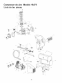
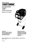
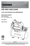
Compresor de aire Modeio 16478
Lista de ias piezas
2s
17_
/6_
_
/8--
/
2o _I
_66
VIEW: A - A
S
/
32 --_
33 _,
_'\,
/'
37 _
20
/
45
Compresor de aire Modeio 16478
Lista de ias piezas
Cantidad
# Juego
#
L Ref.
1
2
3
3
3
3
4
5
6
1&3
3
3
7
1&3
8
9
1&3
2&3
#
Pieza
Descripci6n
Ref. Juego Pieza
#
#
#
45
8
1
46
47
1
2
48
49
5O
Junta,placa de v_lvula
2
1
Juntade cilindro,placa de v_lvula
E101113 Cilindro
1
1
51
52
5
4
1
53
5
1
1
54
55
5
E100227 Culatade cilindro
Juntade culata,placade v_lvula
E100228 Placade v_lvula
E100229 Wlvula
Tornillo,SHC M6 x 1.0 x 20 mm
3
11
1&3
Juntade cilindro,inferior
12
13
14
2&3
2&3
2&3
Excentricopara L1
Tuerca,hex, M6xl.0
Tornillo,SHC M6 x 1.0 x 20 mm
15
2&3
Conjunto,pist6n/ biela L1
1
1
56
57
16
17
1&3
3
Deflectorpara L1
E100087 Tap6nde rellenode aceite/ sinanillo
1
1
58
59
18
19
20
3
3
3
E100566 Tapade c_rter para L1
E100078 Tap6n,visor de nivelde aceite/ conjunta
Tornillo,HFHM5 x 0.8 x 15 mm
1
1
6O
61
E102595 Wlvula de seguridad
E103339 Man6metro,(38 mmw/125 PSI R/L)
E102934 Acoplamiento,tres "T" 1/4 FNPT
Tap6n, 1/4 pulg.NPT
E100724 Boquillade acero 1/4 NPT x 50 mm
E105294
Man6metro,
1
2
Conexi6nr@idade lat6n
1
E101717
67
E105129
Wlvula de drenaje- 1/4 de vuelta
Placa,CraftsmanL14SHPS
TornilloM4 x 10 mm
1
1
4
E100101 Cord6nelectrico,14/3AWG tipo SJT,
1
68
1
1
Nora:Cualquiercampopara los nQmeros/juegosde piezas queno tengan un
6 pi de Iongitud
Conjunto,Motor/Bomba,
nQmeroespecificode pieza,indica queno est_ disponible.Las descripciones
se proveensolamentecomo referencias.La columnacon el nQmerode juego
1
1
1
indica quela pieza ofrecidaest_ disponiblecomo parle de un juego. Una de
cada unade laspiezas est_ ofrecida.
Tapa,filtro
Perno,SHC M8 x 1.25x 25 mm
1
4
Los nQrnerosde losjuegosy las piezasque est_.nincluidosse
describena continuaci6n:
36
(cincadoy cromatadoen amarillo)
Arandelade freno,M8
7
37
Tornillo,HFPHM5 x 0.8 x 10 mm
6
38
39
(cincadoy cromatadoen amarillo)
E101137 Caja
Tornillo,SHC, M8 X 1.25 X 20MM
1
4
40
(cincadoen amarillo)
Arandela,Plana,M8
4
E101346 Placa,soportedel motor
1
1
66
1
2
11
Arandela,planaM8
2
1
E100307
E100248 Condensadorelectricode arranque
Arandelade frenocon dientes,8 mm
Tuerca,M8x1.25,ZDC6.5 mmAir.
N/A
N/A
E100240 Pie aislante(60 mmdi_. X 28 mmair.)
Tornillo,hex.embridado,M8 x 1.25x 50 mm
2
1
65
3
3
3
41
42
43
44
2
1
1
1
25
26
27
28
29
4
Casquillo,1/4 pulg.
E100736 Conjunto,interruptor,presi6n(125 PSI)
E100594 Sujeci6n,cord6nelectrico- 14/3SJT
1
E100860 Ventilador,Motor F1 125mm
Anilloel_stico,exterior, 15 mm
E100247 Condensadorelectricode marcha
34
35
1/4 pulg.Cu 10.8pulg de Iongitud
Tuerca,compresi6n,1/4 pulg.
(50 mm 125PSI R/L,1/8 pulg.NPT)
E101350 Boquillade acero 1/4 NPT x 75 mm
E100210 Regulador,3-puertos,1/8 NPT man6metro
de Puerto
3
3
3
L1B2con escape izquierdo
Base,Filtro de aire
E100435 Elemento,filtro de entradade aire
E100809 Conexi6nen codo,3/8NPTx 3/8 compresi6n 1
Tubo,aliviode presi6n,
1
63
64
22
23
24
4
4
1
1
3
32
33
E101208 Wlvula de seguridad,puertosuperior
E105419 Tubode salida, Macho/Hembra
62
21
3
1
4
(cincadoen amarillo)
Motor/Bomba,L1B2
31
N/A
N/A
(Acero inox. flexible) (127 ram)
10
30
Cantidad ]
Conjuntode tanque,4 galonesSS L14SHPS 1
N/A
4
Tornillo,M6 X 1.0 mmX 30 mm
Arandelade frenoM6
Descripci6n
Juego # PiezaNo.
1
2
3
4
5
4
3
3
1
Descripci6n
E100959 Juego,junta
E100251 Juego,pist6n*
E105222 Juego,conjunto,MotodBomba,
L1B2 conescapeizquie_o
E100794 Juego, Filt_ de aim
E105223 Juego,Tubo, aliviode
p_si6n 1_ pulg.Cu
Ref.#
4,7,8,11,16
9,12-15
1-27,31
32-34
52-54
* NOTA: Pidael juego de juntas# 1tambien,cuandopida este juego.
21
Your Home
For repair - in your home - of all major brand appliances,
lawn and garden equipment, or heating and cooling systems,
no matter who made it, no matter who sold it!
For the replacement parts, accessories and
owner's manuals that you need to do-it-yourself.
For Sears professional installation of home appliances
and items like garage door openers and water heaters.
1-800-4-MY-HOME
® (1=800-469=4663)
Call anytime, day or night (U.S.A. and Canada)
www,sears.com
To purchase a protection
or maintenance agreement (Canada)
1-800-827-6655
(U.S.A.)
Para pedir servicio de reparaci6n
a domicilio, y para ordenar piezas:
1-888=SU-HOGAR
(1-888-784-6427)
SM
www.sears.ca
agreement (U.S.A.)
on a product serviced
1-800-361-6665
by Sears:
(Canada)
Au Canada pour service en frangais:
1-800-LE-FOYER
Mc
(1-800-553-6937)
www.sears.ca
® Registered Trademark/ TMTrademark/SMService
Mark of Sears, Roebuck and Co.
® Marca Registrada/ TMMarca de F_brica/S_Marca de Servicio de Sears, Roebuck and Co.
MC Marque de commerce/{_DMarque
d&posee de Sears, Roebuck and Co.
© Sears, Roebuck
and Co., Sears Canada Inc.