1
HEC SERVICE MANUAL
HEC-Series Service Manual
i
TABLE OF CONTENTS
Table Of Contents
Models HEC-10, HEC-20, HEC-30 & HEC-40
Page No.
1. INTRODUCTION
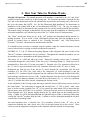
A Brief History of Our Company ................................................................................................................ 1-1
Vogt Energy-Saving Tube-Ice® Machines................................................................................................... 1-1
Preview
.................................................................................................................................................... 1-1
Important Safety Notice............................................................................................................................... 1-2
Special precautions to be observed when charging refrigeration systems ................................................... 1-2
Safety Symbols & What They Mean ........................................................................................................... 1-3
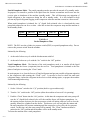
Tube-Ice® Machine, FIGURE 1-1............................................................................................................... 1-4
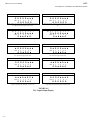
Assembly Drawing Model HEC-30 Air-Cooled, FIGURES 1-2A & 1-2B ................................................. 1-5&1-6
Assembly Drawing Model HEC-30 Water Cooled, FIGURES 1-3A & 1-3B ............................................. 1-7&1-8
Piping Nomenclature ................................................................................................................................... 1-9
2. RECEIPT OF YOUR TUBE-ICE® MACHINE
Inspection ................................................................................................................................................... 2-1
Safety Valves............................................................................................................................................... 2-1
Machine Room ............................................................................................................................................ 2-1
Storage
.................................................................................................................................................... 2-1
3. INSTALLING YOUR TUBE-ICE® MACHINE
Installation Without Bin .............................................................................................................................. 3-1
Bin Installation ............................................................................................................................................ 3-1
Two Methods Of Lifting & Setting Machine On a Level Ice Storage Bin................................................... 3-1
Forklift-&-Blocks Method, FIGURE 3-1 ............................................................................................. 3-2
Forklift-&-Rope Or Lifting Straps Method, FIGURE 3-2.................................................................... 3-3
Wiring and Electrical Connection................................................................................................................ 3-4
Power Connection, FIGURE 3-3 ................................................................................................................. 3-4
Piping and Drain Connections ..................................................................................................................... 3-5
Water Supply and Drains, TABLE 3-1........................................................................................................ 3-5
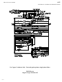
Space Diagram (Water Cooled), FIGURE 3-4 ............................................................................................ 3-6
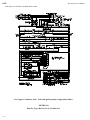
Space Diagram (Air-Cooled), FIGURE 3-5 ................................................................................................ 3-7
Air-Cooled Condenser Installation ............................................................................................................. 3-8
Additional Refrigerant Requirements, TABLE 3-2 ..................................................................................... 3-9
Air-Cooled Condenser Data, TABLE 3-3 ................................................................................................... 3-10
Condenser Dimensions (Condenser pictured DD-101 or DD-131), FIGURE 3-6....................................... 3-11
10/23/01
HEC-Series Service Manual
ii
TABLE OF CONTENTS
Page No.
Condenser Field Piping, FIGURE 3-7......................................................................................................... 3-11
Equivalent Feet of Fittings Due to Friction, TABLE 3-4 ............................................................................ 3-12
Minimum Traps For Discharge Lines, FIGURE 3-8 ................................................................................... 3-12
Condenser Piping, FIGURE 3-9 .................................................................................................................. 3-13
Wiring For DD-41 & DD-61, FIGURE 3-10 .............................................................................................. 3-14
Wiring For DD-101 & DD-131, FIGURE 3-11 .......................................................................................... 3-14
Air-Cooled Condenser Enclosure, FIGURE 3-12........................................................................................ 3-15
Field Attachment Air-Cooled Condenser Refrigerant Tubing, FIGURE 3-13............................................ 3-16
Ice Bin Thermostat Bulb Installation........................................................................................................... 3-17
Location of Thermostat Bulbs In Ice Storage Bin, FIGURE 3-14............................................................... 3-17
Wiring For Single Thermostat Operation, FIGURE 3-15............................................................................ 3-18
Installation Review: A Checklist ................................................................................................................ 3-19
4. HOW YOUR TUBE-ICE® MACHINE WORKS
Principle of Operation ................................................................................................................................. 4-1
Piping Diagram With Reference Numbers, FIGURE 4-1............................................................................ 4-2
How Ice Is Stored
Dual Ice .................................................................................................................................................... 4-3
Single Ice .................................................................................................................................................... 4-4
Ice Bin Capacity .......................................................................................................................................... 4-4
Refrigeration System ................................................................................................................................... 4-5
5. INITIAL START-UP AND OPERATION
Start-up Checklist ........................................................................................................................................ 5-1
Solenoid Valve (Liquid Line), FIGURE 5-1 ............................................................................................... 5-2
Refrigerant Charge ...................................................................................................................................... 5-3
Total Pump Down Mode ............................................................................................................................ 5-3
Piping Schematic Air-Cooled, FIGURE 5-2................................................................................................ 5-5
Piping Schematic Water Cooled, FIGURE 5-3 ........................................................................................... 5-6
6. ELECTRICAL CONTROLS & THEIR FUNCTIONS
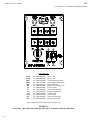
Control Panel, FIGURE 6-1 ........................................................................................................................ 6-1
Description of Control Panel Parts .............................................................................................................. 6-2
Switch Box, FIGURE 6-2............................................................................................................................ 6-3
Description of Switch Box Parts.................................................................................................................. 6-4
10/23/01
HEC-Series Service Manual
iii
TABLE OF CONTENTS
Page No.
PLC Features & Functions........................................................................................................................... 6-5
PLC Control Sequence Flow Chart, FIGURE 6-3................................................................................ 6-6
PLC Mode Identification & Operation ................................................................................................. 6-7
PLC Start-Up Mode.............................................................................................................................. 6-7
PLC Stand-By Mode ............................................................................................................................ 6-8
PLC Freeze Mode................................................................................................................................. 6-8
PLC Harvest Mode............................................................................................................................... 6-8
PLC Partial Pump-Down Mode............................................................................................................ 6-9
PLC Total Pump-Down Mode.............................................................................................................. 6-9
PLC Clean Mode .................................................................................................................................. 6-10
PLC Troubleshoot Mode ...................................................................................................................... 6-10
PLC Fault Identity, TABLE 6-2 ........................................................................................................... 6-11
PLC Display, FIGURE 6-4................................................................................................................... 6-12
PLC Inputs & Outputs, TABLE 6-3 ..................................................................................................... 6-12
PLC Modes, FIGURE 6-5 .................................................................................................................... 6-13
Machine Off (Dual Ice), FIGURE 6-6......................................................................................................... 6-14
Machine Off (Single Ice), FIGURE 6-6A.................................................................................................... 6-15
Freeze Cycle (Dual Ice), FIGURE 6-7 ........................................................................................................ 6-16
Freeze Cycle (Single Ice), FIGURE 6-7A ................................................................................................... 6-17
Harvest Cycle (Dual Ice), FIGURE 6-8....................................................................................................... 6-18
Harvest Cycle (Single Ice), FIGURE 6-8A ................................................................................................. 6-19
Clean Cycle (Dual Ice), FIGURE 6-9.......................................................................................................... 6-20
Clean Cycle (Single Ice), FIGURE 6-9A..................................................................................................... 6-21
7. MAINTENANCE
Ice-making Section ...................................................................................................................................... 7-1
Cleaning Procedure ..................................................................................................................................... 7-1
Water Distributors ....................................................................................................................................... 7-2
Water Tank .................................................................................................................................................. 7-2
Drip Pan .................................................................................................................................................... 7-2
Water Cooled Condensers ........................................................................................................................... 7-2
Draining .................................................................................................................................................... 7-3
Chemical Cleaning....................................................................................................................................... 7-4
Mechanical Cleaning ................................................................................................................................... 7-5
Part I. .................................................................................................................................................... 7-5
Part II.................................................................................................................................................... 7-5
Air-Cooled Condenser Cleaning.................................................................................................................. 7-5
10/23/01
HEC-Series Service Manual
iv
TABLE OF CONTENTS
Page No.
Lubrication .................................................................................................................................................. 7-6
Compressor........................................................................................................................................... 7-6
Cutter Gear Reducer ............................................................................................................................. 7-6
Preventative Maintenance............................................................................................................................ 7-7
Daily Checklist ..................................................................................................................................... 7-7
Note To Manager or Owner ................................................................................................................. 7-7
Preventive Maintenance Program......................................................................................................... 7-8
8. TROUBLESHOOTING (A Checklist)
Machine Won’t Run .................................................................................................................................... 8-1
Freeze-up Due To Extended Freezing Period .............................................................................................. 8-2
Freeze-up Due To Ice Failing To Discharge ............................................................................................... 8-3
Low Ice Capacity......................................................................................................................................... 8-4
Safety Pressure Switches Stop Machine ...................................................................................................... 8-5
Motor Overload Protectors Stop Machine ................................................................................................... 8-6
9. SERVICE OPERATIONS
Adjustable Blowdown (For Clearer Ice)...................................................................................................... 9-1
Automatic Blowdown (Harvest Cycle)........................................................................................................ 9-1
Float Valve (Make-Up Water)..................................................................................................................... 9-1
Expansion Valve.......................................................................................................................................... 9-1
Expansion Valve Adjustment Procedure & Installation .............................................................................. 9-2
Recommended Superheat Setting, TABLE 9-1 ........................................................................................... 9-2
Freezer Pressure Switches ........................................................................................................................... 9-3
Freezer Pressure Switch (Allen-Bradley), FIGURE 9-1.............................................................................. 9-3
Allen Bradley Switch................................................................................................................................... 9-4
High/Low Pressure Switch .......................................................................................................................... 9-4
High/Low Pressure Switch, FIGURE 9-2.................................................................................................... 9-5
Head Pressure .............................................................................................................................................. 9-5
Air-Cooled Units ......................................................................................................................................... 9-5
Water Regulating Valve, FIGURE 9-3........................................................................................................ 9-6
Condenser Fan Switch, FIGURE 9-4........................................................................................................... 9-6
Water Cooled Units ..................................................................................................................................... 9-6
Compressor Crankcase Heater..................................................................................................................... 9-6
Ice Bin Thermostat(s) Adjustments ............................................................................................................. 9-6
Ice Bin Thermostat, FIGURE 9-5................................................................................................................ 9-7
Thawing Timer, FIGURE 9-6...................................................................................................................... 9-8
Thawing Timer ............................................................................................................................................ 9-8
Page No.
10/23/01
HEC-Series Service Manual
v
TABLE OF CONTENTS
Ice Selector Switch, FIGURE 9-7................................................................................................................ 9-8
Ice Selector Switch ...................................................................................................................................... 9-8
Control Circuit Protection ........................................................................................................................... 9-9
Circulating Water Pump Motor ................................................................................................................... 9-9
Condenser Cleaning..................................................................................................................................... 9-9
Air-Cooled Condenser ................................................................................................................................. 9-10
Cutter Gear Reducer .................................................................................................................................... 9-10
Cutter Bearing ............................................................................................................................................. 9-10
Cutter and Gear Drive.................................................................................................................................. 9-11
Cutter-Water Tank Assembly, FIGURE 9-8................................................................................................ 9-12
Cutter-Water Tank Parts, FIGURE 9-9 ....................................................................................................... 9-13
Cutter Drive Parts, FIGURE 9-10 ............................................................................................................... 9-14
Cutter Parts, FIGURE 9-11 ......................................................................................................................... 9-15
Ice Discharge Arrangement, FIGURE 9-12................................................................................................. 9-16
Pumping Down Freezer ............................................................................................................................... 9-17
Removal Of Refrigerant From Machine ...................................................................................................... 9-17
Refrigerant Leaks ........................................................................................................................................ 9-18
Non-Condensable Gases.............................................................................................................................. 9-18
Compressor Motor Burnout......................................................................................................................... 9-18
Solenoid Valve (Liquid Line and Thawing Gas), FIGURE 9-13................................................................. 9-19
Solenoid Valves........................................................................................................................................... 9-19
Water Distributors ....................................................................................................................................... 9-19
Water Tank .................................................................................................................................................. 9-20
CPR (Crank Pressure Regulator), FIGURE 9-14 ........................................................................................ 9-20
CPR Valve Settings, TABLE 9-2 ................................................................................................................ 9-21
Cylinder Ice to Crushed Ice Conversion...................................................................................................... 9-21
Cylinder to Crushed, Terminal Block jumper Locations, FIGURE 9-15 ............................................. 9-21
Recommended Freezer Pressure Setting, TABLE 9-3.......................................................................... 9-22
Freezer Pressure Switch, FIGURE 9-16 ............................................................................................... 9-22
Recommended Ice Weights/Cycle, TABLE 9-4................................................................................... 9-23
Single to Dual Ice Conversion.............................................................................................................. 9-23
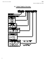
10. MODEL NUMBER STRUCTURE FOR HEC MACHINES................................................................ 10-1
10/23/01
HEC-Series Service Manual
vi
TABLE OF CONTENTS
Page No.
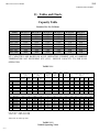
11. TABLES AND CHARTS
Ice Capacity TABLE 11-1 ........................................................................................................................... 11-1
Normal Operating Vitals, TABLE 11-2 ...................................................................................................... 11-2
Temperature-Pressure Chart, TABLE 11-3 ................................................................................................. 11-3
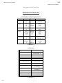
English-Metric Conversion, TABLE 11-4................................................................................................... 11-4
12. TECHNICAL SERVICE BULLETINS .................................................................................................. 12-1
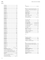
13. INDEX
10/23/01
.................................................................................................................................................... 13-1
HEC-Series Service Manual
1-1
INTRODUCTION
1. Introduction
Henry Vogt Machine Co.
A Brief History Of Our Company. Henry Vogt Machine Co. was founded as a small
machine shop in Louisville, Kentucky in 1880. Today, Vogt Tube Ice, LLC is one of the
world’s leading producers of ice-making equipment.
In 1938, Vogt built the first Tube-Ice® machine and revolutionized the ice-making industry.
Our first “sized-ice” machine quickly replaced the old can-ice plants, which required much
hard labor and large amounts of floor space for freezing, cutting, and crushing ice by hand.
Vogt Energy-Saving Tube-Ice Machines Are Cost Effective. Today, Vogt Tube-Ice®
machines enjoy a well-earned reputation as the most energy efficient, dependable ice-making
equipment in the world.
Using as little as one-half to one-third the energy required by competitors’ ice makers, TubeIce® machines produce the same amount of ice--in restaurants, sports arenas, packing plants,
and wholesale operations around the globe--at great savings.
In addition, Tube-Ice® machines are renowned for their long life, giving many customers more
than 35 years of dependable service. Ask someone who owns one.
Preview. All the skill in engineering and fabrication that we’ve learned in over a century of
experience is reflected in the HEC model Tube-Ice® machines. Since Vogt introduced TubeIce® machines in 1938, the process of making Tube-Ice® ice has been widely recognized as the
most economical means of production. The machine’s economic and reliable operation have
been proven over and over again, in a network of varied types of installations throughout the
world.
Furnished with your machine is the Certificate Of Test--the report of operating data which is a
record of the unit’s satisfactory operation at our factory test floor. It is evidence of our desire
to deliver to you “the finest ice-making unit ever made.”
This manual is designed to assist you in the installation, start-up, and maintenance of your
unit. Your Tube-Ice® machine will give you a lifetime of service when you install it, maintain
it, and service it properly.
Please read your manual carefully before attempting installation, operation, or servicing of this
professionally-designed piece of equipment. Also, make sure the Warranty Registration/Startup Report is completed and returned.
If you have additional questions, please call your distributor. Also, feel free to phone the
factory direct at (502) 635-3000 or toll free (800) 853-VOGT.
10/24/01
HEC-Series Service Manual
1-2
INTRODUCTION
Important Safety Notice. This information is intended for use by individuals possessing
adequate backgrounds of electrical, refrigeration and mechanical experience. Any attempt to
repair major equipment may result in personal injury and property damage. The manufacturer
or seller cannot be responsible for the interpretation of this information, nor can it assume any
liability in connection with its use.
Special Precautions To Be Observed When Charging Refrigeration Systems. Only
technically-qualified persons, experienced and knowledgeable in the handling of refrigerant
and operation of refrigeration systems, should perform the operations described in this
manual. All local, federal, and EPA regulations must be strictly adhered to when handling
refrigerants.
If a refrigeration system is being charged from refrigerant cylinders, disconnect each cylinder
when empty or when the system is fully charged. A gage should be installed in the charging
line to indicate refrigerant cylinder pressure. The cylinder may be considered empty of liquid
HCFC-22 refrigerant when the gauge pressure is 25 pounds or less, and there is no frost on
the cylinder. Close the refrigerant charging valve and cylinder valve before disconnecting the
cylinder. Loosen the union in the refrigerant charging line--carefully to avoid unnecessary and
illegal release of refrigerant into the atmosphere.
! CAUTION !
Immediately close system charging valve at commencement of defrost or thawing cycle
if refrigerant cylinder is connected. Never leave a refrigerant cylinder connected to
system except during charging operation. Failure to observe either of these precautions
can result in transferring refrigerant from the system to the refrigerant cylinder, overfilling it, and possibly causing the cylinder to rupture because of pressure from
expansion of the liquid refrigerant brought on by an increase in temperature.
! CAUTION !
Always store cylinders containing refrigerant in a cool place. They should never be exposed
to temperatures higher than 125°F and should be stored in a manner to prevent abnormal
mechanical shocks.
Also, transferring refrigerant from a refrigeration system into a cylinder can be very dangerous
and is not recommended.
! CAUTION !
It is not recommended that refrigerant be transferred from a refrigeration system
directly into a cylinder. If such a transfer is made, the refrigerant cylinder must be an
approved, CLEAN cylinder--free of any contaminants or foreign materials--and must
be connected to an approved recovery mechanism with a safety shutoff sensor to assure
contents do not exceed net weight specified by cylinder manufacturer or any applicable
code requirements.
! CAUTION !
10/24/01
HEC-Series Service Manual
1-3
INTRODUCTION
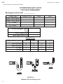
Safety Symbols & What They Mean. Prior to installation or operation of the Tube-Ice® machine,
please read this manual. Are you familiar with the installation, start-up, and operation of a Tube-Ice®
machine? Before you operate, adjust or service this machine, you should read this manual,
understand the operation of this machine, and be aware of possible dangers.
These safety symbols will alert you
when special care is needed.
Please heed.
! DANGER !
Indicates an immediate hazard and that special precautions
are necessary to avoid severe personal injury or death.
! DANGER !
! WARNING !
Indicates a strong possibility of a hazard and that an
unsafe practice could result in severe personal injury.
! WARNING !
! CAUTION !
Means hazards or unsafe practices could result
in personal injury or product or property damage.
! CAUTION !
10/24/01
HEC-Series Service Manual
1-4
INTRODUCTION
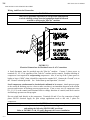
VOGT
TUBE-ICE MACHINE
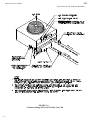
FIGURE 1-1
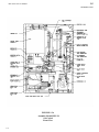
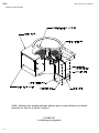
Tube-Ice machine shown atop a typical ice storage bin with a condensate drain pan.
The bin and drain pan are optional equipment
NOTICE! The ice storage bin is shown for illustration purposes only. Vogt Tube Ice, LLC accepts no
responsibility for the selection or use of any ice bin in conjunction with the Tube-Ice machine.
10/24/01
HEC-Series Service Manual
1-5
INTRODUCTION
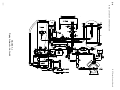
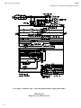
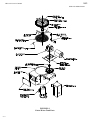
FIGURE 1-2A
Assembly Model HEC-30
Air-Cooled
Front View
10/24/01
HEC-Series Service Manual
1-6
INTRODUCTION
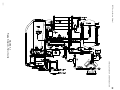
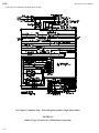
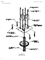
FIGURE 1-2B
Assembly Model HEC-30
Air-Cooled
Rear View
10/24/01
HEC-Series Service Manual
1-7
INTRODUCTION
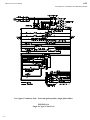
FIGURE 1-2C
Assembly Model HEC-30
Water Cooled
Front View
10/24/01
HEC-Series Service Manual
1-8
INTRODUCTION
FIGURE 1-3B
Assembly Model HEC-30
Water Cooled
Rear View
10/24/01
HEC-Series Service Manual
1-9
INTRODUCTION
PIPING SCHEMATIC NOMENCLATURE
1.
Freezer
3.
Compressor
4PS. High/Low Safety Pressure Switch
30.
Gage Glass
5M. Cutter Motor
32.
AC Condenser Service Connection
5R. Cutter Gear Reducer
34.
Compressor Suction Service Valve
6.
Water Pump
35.
Comp. Discharge Service Valve
7.
Water Tank (reservoir)
39. Water Tank Drain Valve
8.
Freezer Cover
40. Automatic Blowdown Piping
12.
Make-Up Float Valve
41. Condenser Water Regulating Valve
13.
Heat Exchanger
43. Strainer
14.
Condenser
46. Filter Drier
15R. Receiver
48. Muffler
16.
Thaw Chamber
50. Receiver Relief Valve
17.
Expansion Valve
51. Freezer Relief Valve
18.
Thaw Gas Solenoid Valve “D”
53. Discharge Line Solenoid Valve “X”
20.
Liquid Line Solenoid Valve “A”
56. Freezer Pressure Switch
23.
Condenser Water In Connection
58. Liquid Outlet Valve “King”
23A. Make-Up Water Inlet Connection
69. Low Pressure Stop Valve
24.
Condenser Water Out Connection
88. Accumulator
25.
Water Tank Drain Connection
91. Liquid Return Stop Valve
28.
Refrigerant Charging Connection
100. CPR Valve
101. Check Valve
10/24/01
HEC-Series Service Manual
2-1
RECEIPT OF YOUR TUBE-ICE MACHINE
2. Receipt Of Your Tube-Ice Machine
! WARNING !
Only service personnel experienced and certified in refrigeration and qualified to work
with high voltage electrical equipment should be allowed to install or work
on this Tube-Ice® machine.
! WARNING !
Inspection. As soon as you receive your machine, inspect it for any damage. If damage is
suspected, note it on the shipper’s papers (i.e., the trucker’s Bill of Lading). Immediately make a
separate written request for inspection by the freight line’s agent. Any repair work or alteration to
the machine without the permission of the Henry Vogt Machine Co. can void the machine’s
warranty.
The machine was shipped with a full charge of HCFC-22 stored in the receiver. Visually check all
lines for mechanical damage. If a leak is suspected, check all joints with a Halogen Leak Detector.
All leaks should be reported to the Henry Vogt Machine Co. to obtain authorization for repair.
Safety Valves. Two safety pressure relief valves are an integral part of the packaged Tube-Ice®
machine. One is located in the low-side of the system on the freezer and one is in the high side of
the system on the receiver. You must vent each of the pressure relief valves to the atmosphere in
such a manner as to comply with local and national codes.
Machine Room. The machine must be located inside a suitable building and must not be subjected
to ambient temperatures below 50?F (10?C) or above 110?F (43.3?C). Heat radiation from other
sources (sunlight, furnaces, condenser, etc.) and unusual air current may affect the operation of the
machine and should be avoided. The electrical components of the Tube-Ice® machine are rated
NEMA 1. Therefore, the machine should not be located in a hazardous area.
Storage (prior to installation or start-up). The machine must not be stored or installed in an area
that is subject to reach temperatures at or above 115?F (46.1?C).
Important Notice. The Warranty/Registration Start-Up Report must be completed and returned to
the Henry Vogt Machine Co. to initiate and assure a full warranty.
10/23/01
HEC-Series Service Manual
3-1
INSTALLING YOUR TUBE-ICE MACHINE
3. Installing Your Tube-Ice Machine
Note: A video production is available through your distributor.
Installation Without Bin. Machine must be installed on a drainable condensate drip pan.
Bin Installation. Set the bin on solid, level footing. Inside the bin you will find the four legs. Screw
these legs to the bottom of the bin. You can make MINOR leveling adjustments by using these legs
as leveling screws, as outlined in the manufacturer’s instructions.
Once the ice storage bin is level, the Tube-Ice® machine can be elevated and placed inside the
condensate drip pan on the top of the bin.
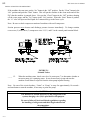
FIGURES 3-1 and 3-2 illustrate two methods of lifting & setting Tube-Ice® machine on a level ice
storage bin.
! CAUTION !
The approximate weight of the machine is 1360 pounds. Always use
equipment with adequate load-carrying capacity.
! CAUTION !
10/21/01
HEC-Series Service Manual
3-2
INSTALLING YOUR TUBE-ICE MACHINE
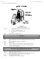
FIGURE 3-1
Forklift-&-Blocks Method
You need:
+
+
+
+
forklift truck with adequate load and height capacities
(8) 2X4 wood blocks 8 in. long
(2) wooden 2X4’s measuring 3-ft. long
pry bar
Step 1.
Position Tube-Ice® machine on forks.
! CAUTION !
The Tube-Ice machine may be somewhat top heavy on the rear.
! CAUTION !
®
Step 2.
Step 3.
Step 4.
Step 5.
Step 6.
Stack wood blocks in each corner of the drip pan on top of the ice storage
bin.
Lift and set Tube-Ice® machine on wood blocks.
Remove forklift.
Stack 3-ft. long 2X4’s beside drip pan, overlapping front and back of bin.
Using a pry bar with fulcrum on 2X4’s, raise side of machine enough to
remove the TOP wood blocks.
! CAUTION !
Do not remove top AND bottom blocks at the same time.
! CAUTION !
Step 7.
Step 8.
Repeat steps 5 and 6 on other side.
With machine sitting on one (1) block under each corner, repeat steps 5, 6,
and 7 remove remaining blocks. Drip pan flanges may bend slightly.
Step 9.
Straighten bent drip pan flanges.
Step 10.
Check alignment of ice chute to bin opening.
10/21/01
HEC-Series Service Manual
3-3
INSTALLING YOUR TUBE-ICE MACHINE
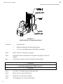
FIGURE 3-2
Forklift-&-Rope or Lifting Straps Method
You need:
+
extra head room
+
forklift with adequate load and height capacities
+
1/2” rope or four lifting straps to bind forks to top angles
Step 1.
Remove front, rear, and top access panels.
Step 2.
Position fork truck so that forks are resting flat on top angles of Tube-Ice®
machine.
Step 3.
Use the rope or straps to securely bind forks to the top angles.
! CAUTION !
Be sure the bin is level and is set in its proper location.
See the space diagrams, FIGURE 3-4 and 3-5.
! CAUTION !
10/21/01
Step 4.
Lift Tube-Ice® machine and set into drip pan of bin.
Step 5.
Remove rope or straps and fork truck.
Step 6.
Install front, rear and top access panels.
Step 7.
Check alignment of ice chute to bin opening.
HEC-Series Service Manual
3-4
INSTALLING YOUR TUBE-ICE MACHINE
Wiring And Electrical Connection.
! WARNING !
Only service personnel experienced in refrigeration and qualified
to work with high voltage electrical equipment should be allowed
to install or work on the Tube-Ice® machine.
! WARNING !
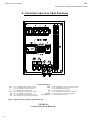
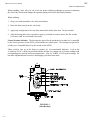
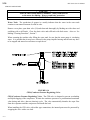
FIGURE 3-3
Electrical Connections for Machine Power & AC Connections
A fused disconnect must be provided near the Tube-Ice® machine. Connect 3 phase power to
terminals L1, L2, L3 for operation of the Tube-Ice® machine and its controls. Rotation checking of
compressor is not required for reciprocating compressors. Also, if one leg of the 3 phase power is
higher or lower (“Wild”), then it should be connected to terminal #L2. Connect the “Ground” wire to
the “Ground” terminal provided. See “Initial Start-up and Operation”, Section 5.
Scroll compressor rotation must be checked and confirmed to be correct. Attach pressure gages
to the suction & discharge service valves to make sure there is an immediate decrease in the suction
pressure and increase in discharge pressure upon start up. If not, reverse two (2) compressor wires
(L1, L2, L3) at the control panel terminal block to change direction of rotation, and check suction
and discharge pressure on start up again.
Do not switch leads directly at the compressor. Terminals L4 and L5 are for connection of single
phase 208/230 electrical supply for split voltage applications such as 460 volt, 3 phase for
compressor.
! CAUTION !
Do not attempt to start machine prior to connecting water lines
and making the following NECESSARY provisions.
Refer to FIGURES 3-4 & 3-5 (space diagrams) for correct installation.
! CAUTION !
10/21/01
HEC-Series Service Manual
3-5
INSTALLING YOUR TUBE-ICE MACHINE
Piping and Drain Connections. All connections are located at the rear of the machine. Look for
four water connections on the freezing unit of each water cooled machine. See Space Diagram,
FIGURE 3-4 for correct utility connections.
! CAUTION !
Exterior shut-off valves must be provided in the water inlet lines.
The minimum inlet water pressure for
satisfactory operation of the machine is 30 psig.
The maximum allowable pressure is 100 psig.
! CAUTION !
Model
Make Up Water In
HEC-10
3/8” FPT
HEC-20
3/8” FPT
HEC-30
3/8” FPT
HEC-40
3/8” FPT
Water Tank Drain
3/4” FPT
3/4” FPT
3/4” FPT
3/4” FPT
Condenser Water In
3/4” FPT
3/4” FPT
3/4” FPT
1” FPT
Condenser Water Out
3/4” FPT
3/4” FPT
3/4” FPT
1” FPT
TABLE 3-1
Water Supply and Drains
When the ice machine sits on a storage bin, the bin must be provided with a drip pan for catching the
condensate from the ice machine. Separate drains for the condensate and for the bin are necessary.
See FIGURE 3-4 or 3-5 (space diagram drawings for typical water and drain connections).
Condensate drain must not run through the ice compartment of the bin.
The condenser water outlet, water pan drain, condensate drain and ice storage bin drain connections
must be extended to an open drain or sump and arranged for visible discharge.
! CAUTION !
These lines must NOT be connected into a pressure tight common header
due to the possibility that warm condenser water
may back up into the water pan, drip pan or the ice storage bin. The
condenser water outlet MUST be piped separately to the drain.
! CAUTION !
10/21/01
3-6
FIGURE 3-4
Space Diagram Water Cooled Machine
INSTALLING YOUR TUBE-ICE MACHINE
10/21/01
HEC-Series Service Manual
HEC-Series Service Manual
10/21/01
3-7
INSTALLING YOUR TUBE-ICE MACHINE
FIGURE 3-5
Space Diagram Air-Cooled Machine
HEC-Series Service Manual
3-8
INSTALLING YOUR TUBE-ICE MACHINE
Air-Cooled Condenser Installation Instructions.
! WARNING !
Using a non-Vogt condenser will void the compressor warranty.
! WARNING !
Certain installation guidelines must be followed to obtain reliable operation from air-cooled ice
machines. If these guidelines are not followed, the compressor warranty will not be honored. Any
exceptions to this policy must be obtained in writing prior to installation and operation of the ice
machine.
1.
Outdoor condensers must be installed with vertical air flow. Indoor condensers used for heat
recovery may be installed with either horizontal or vertical air flow.
2.
The preferred condenser location is above the ice machine, with liquid refrigerant from the
condenser outlet draining freely (1/4” per foot slope) in the direction of normal operating flow
(back to the ice machine) with no traps in the liquid line.
3.
If it is absolutely necessary to install the condenser below the ice machine, certain conditions
MUST be met. The refrigerant connections on the condenser must be no more than 6 feet below
the refrigerant connections on the ice machine. The return liquid line from the condenser must
rise no more than 12 feet before dropping back down to the elevation of the ice machine. When
the condenser is located below the ice machine, expect a 16 psig increase in head pressure and at
least 3% reduction in capacity.
4.
Flooding head pressure controls such as Alco Headmaster are not to be used, since they cause
excessive subcooling of the returned liquid refrigerant and interfere with reliable ice harvest.
5.
The discharge and liquid lines must be insulated with 1/2” thick Armaflex insulation or equal.
6.
Horizontal runs in the discharge line should slope 1/4” per foot in the normal direction of flow
(away from the ice machine).
7.
Traps must be installed in discharge lines at the base of all vertical risers. There should be no
intentional traps in liquid lines. Trap volume should be kept to a minimum. Typical details are
shown in FIGURE 3-8.
8.
Use only ACR grade copper pipe, Type L. Recommended line sizes are shown in TABLE 3-2.
9.
Distance between ice machine and condenser must not exceed 150 equivalent feet. Refer to
Condenser Equivalent Line Size worksheet.
10. Condensers must be provided with a cold weather valve kit per FIGURE 3-7. These valves
allow one-half of the condenser to be disabled in cold weather. Running the ice machine with
one half the condenser in cold weather makes it easier to maintain minimum necessary
condensing pressure, particularly in windy conditions.
10/21/01
HEC-Series Service Manual
3-9
INSTALLING YOUR TUBE-ICE MACHINE
11. Condensers with multiple fans must be provided with a thermostat to turn off unneeded fans in
cold weather, per FIGURE 3-9. Turning off unneeded fans reduces on-off cycling of the fan(s)
and allows for a steadier condensing pressure.
12. When extreme cold conditions are expected or encountered (temperatures below 0°F and wind
greater than 15 MPH), it may be necessary to install a protective enclosure around the condenser.
A typical enclosure is shown in FIGURE 3-12. Other apparatuses such as louvers may be used.
Contact the factory for suggestions.
13. After installation, the field-installed lines are to be evacuated to a vacuum of 500 microns or less
and held for at least one hour. After the vacuum pump is removed, vacuum should hold at 500
microns or less for at least 5 minutes and the lines pressurized with R-22 to 25 psig minimum.
14. The volume of refrigerant supplied with the machine is sufficient to fill the condenser and
condenser lines when length of pipe (one way) is 75 feet or less. When the length of lines is
longer than 75 feet, additional refrigerant must be added as follows:
Liquid Line Size
1/2”
5/8”
7/8”
1-1/8”
75 ft.
none
none
none
none
100 ft.
125 ft.
none
none
2
4
4
8
6
12
Table 3-2
Pounds R-22 to Add Vs. Liquid Line Length
150 ft.
2
6
12
18
15. All piping must be done in accordance with applicable local and national codes. Such codes may
include “The Safety Code for Mechanical Refrigeration (ANSI B9.1), and “The Code for
Refrigerant Piping” (ANSI B31.5).
The following installation guidelines are strongly suggested. While they do not affect the machine
warranty, they may be required for safe operation, and to comply with all applicable electrical and
mechanical codes.
16. Local electrical code must be checked for wiring method.
17. The installer must provide a lockable, fused disconnect switch(s) adjacent to the condenser.
18. Electrical connections between the condenser and the Tube-Ice® machine require minimum 12 ga.
wire.
19. All electrical fittings and components exposed to the weather must be suitable for outdoor
installation.
The design total heat rejection for each Tube-Ice® machine, the recommended air-cooled condenser,
and condenser physical and electrical data are shown in TABLE 3-3. Only the condensers shown are
UL listed with the ice machines. Other condensers may be individually UL listed, but are not UL
listed with the Tube-Ice® machines, and cannot be recommended by the Henry Vogt Machine Co.
10/21/01
HEC-Series Service Manual
3-10
INSTALLING YOUR TUBE-ICE MACHINE
Catalog energy efficiency ratings of the ice machines are based on use of the recommended
condenser.
Condensers supplied by Vogt must be utilized. The use of non-Vogt condensers will void the
compressor warranty. For continuous operation at ambients above 105°F, consult the factory about
using a larger condenser.
Ice Machine Model
Electrical Frequency, Hz
Recommended Condenser
Total Heat Rejection:
BTU/hr at 60 hz.
BTU/hr at 50 hz.
Fans:
Number
HP, Each
Total, CFM
Full Load Amps:
1 ph., 208/230V, 60 hz.
3 ph., 208/230V, 60 hz.
3 ph., 460V, 60 hz.
1 ph., 230V., 50 hz.
3 ph., 230V., 50 hz.
3 ph., 400V., 50 hz.
Locked Rotor Amps:
1 ph., 208/230V., 60 hz.
3 ph., 208/230V., 60 hz.
3 ph., 460V., 60 hz.
1 ph., 230V., 50 hz.
3 ph., 230V., 50 hz.
3 ph., 400V., 50 hz.
Weight, lbs.:
Net
Shipping
Operating (maximum flooded)
Condenser dimensions (see FIG. 3-6),
inches:
A (Width)
B (Length)
C (Height)
D (Leg centerline)
E (Leg centerline)
F (Clearance below)
Recommended Line Sizes, OD:
Liquid
All lengths and orientations
Discharge Gas
Vertical Up, All lengths
Horiz. Or Down, < 75 ft.
Horiz. Or Down, > 75 ft.
Connections (Cond. & Ice Mach.):
Liquid (ODF)
Discharge Gas (ODF)
HEC-10
60/50
DD-61
HEC-20
60/50
DD-61
HEC-30
60/50
DD-101
HEC-40
60/50
DD-131
28,700
23,900
28,700
23,900
44,500
37,100
80,400
67,000
1
.333
5000
1
.333
5,000
2
.5
9,800
2
.5
9,800
2.5
N/A
N/A
3.0
N/A
N/A
2.5
N/A
N/A
3.0
N/A
N/A
5.0
N/A
N/A
5.8
N/A
N/A
5.0
N/A
N/A
5.8
N/A
N/A
7
N/A
N/A
8.2
N/A
N/A
7
N/A
N/A
8.2
N/A
N/A
15
N/A
N/A
17.5
N/A
N/A
15
N/A
N/A
17.5
N/A
N/A
150
195
167
150
195
167
250
310
276
265
325
301
39”
46”
36”
37-7/8”
37”
16”
39”
46”
36”
37-7/8”
37”
16”
42”
66”
36”
40-3/8”
54”
16”
42”
66”
36”
40-3/8”
54”
14”
1/2”
1/2”
5/8”
7/8”
5/8”
5/8”
7/8’
5/8”
5/8”
7/8”
7/8”
7/8”
1-1/8”
1-1/8”
1-1/8”
1-3/8”
1/2”
5/8”
1/2”
5/8”
5/8”
7/8”
7/8”
1-1/8”
TABLE 3-3
Air-Cooled Condenser Data
10/21/01
HEC-Series Service Manual
3-11
INSTALLING YOUR TUBE-ICE MACHINE
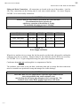
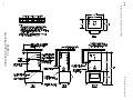
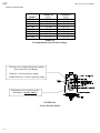
FIGURE 3-6
Condenser Dimensions (Condenser pictured: DD-101 or DD-131)
Note: Dash lines indicate customer supplied piping. The Check Valve in the return line (labeled
“Output To Machine”) is supplied with the condenser.
FIGURE 3-7
Condenser Field Piping
10/21/01
HEC-Series Service Manual
3-12
INSTALLING YOUR TUBE-ICE MACHINE
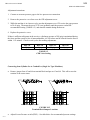
CONDENSER EQUIVALENT
LINE SIZE WORKSHEET
Discharge Gas Line O.D. _____________
Fitting Type
Globe Valve (open)
Angle Valve (open)
45° Elbow
90° Elbow
Number Used
Factor
Total
Feet of Straight Copper
Used
Total Fitting Factor
Total Equivalent Feet
Fitting Factors
Copper Tube O.D. Type “L”
1/2”
5/8”
7/8”
1 1/8”
Globe Valve (open)
14
16
22
28
Angle Valve (open)
7
9
12
15
45° Elbow
.5
1
1
1.5
90° Elbow
1
2
2
3
TABLE 3-4
FIGURE 3-8
Minimum Traps for Discharge Lines
10/21/01
HEC-Series Service Manual
3-13
INSTALLING YOUR TUBE-ICE MACHINE
FIGURE 3-9
Condenser Piping With Cold Weather Valve Kit
10/21/01
HEC-Series Service Manual
3-14
INSTALLING YOUR TUBE-ICE MACHINE
FIGURE 3-10
Wiring For DD-61 With Cold Weather Valve and Single Fan
FIGURE 3-11
Wiring For DD-101 & DD-131 With Cold Weather Valve And Dual Fans
10/21/01
HEC-Series Service Manual
3-15
INSTALLING YOUR TUBE-ICE MACHINE
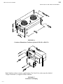
FIGURE 3-12
Air-Cooled Condenser Enclosure
10/21/01
HEC-Series Service Manual
3-16
INSTALLING YOUR TUBE-ICE MACHINE
FIGURE 3-13
Field Attachment, Air Cooled Condenser Refrigerant Tubing
10/21/01
HEC-Series Service Manual
3-17
INSTALLING YOUR TUBE-ICE MACHINE
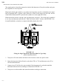
Ice Bin Thermostat Bulb Installation. Each machine is equipped with an ice bin thermostat. To
assure proper protection for the machine, the control bulb of the ice bin thermostat must be located so
that ice will contact it when the bin is full. For a divided bin, locate the control bulbs as illustrated in
FIGURE 3-14. This allows space for the machine to make an additional discharge of ice AFTER the
ice contacts the bulb WITHOUT the ice building up into the discharge opening of the chute.
Note: As an option, the PLC can be programmed for your machine to produce a specified amount of
ice during a certain time each day. Consult the factory for more details.
FIGURE 3-14
Location Of Thermostat Bulbs In Ice Storage Bin
10/21/01
HEC-Series Service Manual
3-18
INSTALLING YOUR TUBE-ICE MACHINE
The control panel is electrically connected so that the bin thermostat will stop the machine only upon
the completion of a harvest period.
When both cylinder and crushed ice are produced and separately stored in a divided bin, the control
bulb of thermostat BT1 is placed in the crushed ice section of the storage bin (left side) and the
control bulb of thermostat BT2 is placed in the cylinder ice section (right side of bin).
When the bin does not have a divider, only one thermostat is necessary. The wiring may be modified
to use only one thermostat and bulb (See “With No Divider in Bin”, Section 4 and FIGURE 3-14).
Or install both bulbs--so that the ice contacts both bulbs when the bin is full.
FIGURE 3-15
Wiring for Single Thermostat Operation (Dual Ice Type Only)
(follow instructions below)
10/21/01
1.
Turn power off to the machine and check with volt meter to make sure panel is dead.
2.
Select the thermostat which will not be used (either CRU or CYL) and disconnect wire #25 or
#26 from that thermostat.
3.
Connect wires #25 & #26 to the same terminal of the thermostat to be used and extend that
thermostat bulb into the bin, mounting it as illustrated in FIGURE 3-14.
4.
Turn power on to the machine and restart the machine according to instructions.
HEC-Series Service Manual
3-19
INSTALLING YOUR TUBE-ICE MACHINE
Installation Review: A CHECKLIST
Make a visual check to be sure these steps have been taken BEFORE continuing.
CHECK: _____ PRIOR TO OPENING VALVES, check all joints for leaks which may have
developed during shipment. {NOTE: The required charge of Refrigerant 22 has been isolated in the
Receiver (15R).}
CHECK: _____ All water supply and drain connections for conformity to requirements stipulated in
this manual. See FIGURES 3-4, 3-5, and TABLE 3-1.
CHECK: _____ Electrical supply for proper size of fuses and for compliance to local and national
codes. See the machine nameplate for minimum circuit ampacity and maximum fuse size.
CHECK: _____ All field installed equipment (air-cooled condenser, ice storage bin, ice spreader,
etc.) for proper installation.
CHECK: _____ The applicable portion of the warranty registration/start-up report for proper
completion.
CHECK: _____ The position of all push button switches to assure they will or will not start
automatically as desired.
NOTE: This machine is controlled by a PLC and can automatically start with power to the machine
after a two hour time lapse if the ice switch is in the on position and all other requirements are met.
10/21/01
HEC-Series Service Manual
4-1
HOW YOUR TUBE-ICE MACHINE WORKS
4. How Your Tube-Ice Machine Works
Principle Of Operation. The manual operation of the machine is controlled by the “Ice” and “Start”
switches located in the switch box of the freezing unit. The automatic operation is controlled by the
PLC and ice bin thermostats which will automatically stop and start the freezing unit by the level of
the ice in the storage bin (NOTE: See “Ice Bin Thermostat Bulb Installation” for instructions on
installation of the control bulb of the ice bin thermostats FIGURE 3-14). The type ice produced
(cylinder or crushed) is determined by the position of the ice selector switch located in the switch box.
The control wiring is arranged so that the unit will stop only upon the completion of a thawing period
and partial pumpdown cycle whether by action of the “Ice” switch or the ice bin thermostats.
The “Clean” switch must always be set in the “Off” position (not illuminated) during normal icemaking operation. It is set on the “Clean” (illuminated) position only when the equipment is to be
cleaned or pumped down as outlined in the “Cleaning Procedure,” and “Total Pump-Down
Procedure”, Section 9, and instructions attached to the machine.
If it should become necessary to instantly stop the machine, either the external disconnect switch,
cutter overload switch, or pump overload switch must be turned off.
FIGURES 4-1, 5-2, & 5-3 illustrate the piping diagram of the refrigerant and water circuits of the
Tube-Ice machines with numbers for easy reference. Throughout this manual the numbers you see
in parentheses refer to the numbers in this piping schematic.
The freezer (2) is a shell and tube-type vessel. During the freezing period, water is constantly
recirculated through the vertical tubes of the freezer by a centrifugal pump (6). Make-up water is
maintained by a float valve (12) in the water tank (7). Solenoid valve (20), sometimes referred to as
the “A” valve, is open and solenoid valve (18), sometimes referred to as the “D” valve, is closed.
Refrigerant gas from the top of the freezer (2) passes through the accumulator (88), the heat
exchanger (13), the CPR valve (100), and to the compressor (3) which discharges it into the
condenser (15). Condensed liquid refrigerant from the condenser flows through the liquid side of the
heat exchanger and into the receiver (15R). Liquid refrigerant from the receiver flows through the
filter/drier (46), the thawing chamber (16) of the freezer, the strainer (43), “A” valve (20), expansion
valve (17), and into the freezer, thereby completing the freezing circuit.
At the completion of the freezing period, thawing is started by action of the freezer pressure switch in
the control panel. The water pump is stopped and solenoid valve “A” (20) is closed. After a time
lapse of seven seconds, solenoid valve “D” (18) is opened, the cutter motor (5M) is started and the
harvest (thaw) timer (FIGURE 9-6) is activated. Warm gas from the receiver is discharged into the
freezer through valve (18), thereby slightly thawing the ice which drops on the rotating cutter for
sizing. Cylinder ice will be discharged through the right half-section of the ice discharge chute when
viewing the Tube-Ice® machine from the front. Crushed ice will be discharged through the left halfsection of the ice discharge chute.
Air-cooled machines have a solenoid valve (53), sometimes referred as the “X” valve, in the
compressor discharge line, and a check valve (101) in the liquid return line to the receiver. These
valves prevent the migration of refrigerant to the condenser when the machine is not operating.
10/21/01
HEC-Series Service Manual
4-2
HOW YOUR TUBE-ICE MACHINE WORKS
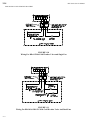
HEC, Water Cooled -- Piping Schematic
FIGURE 4-1
HEC, Air Cooled -- Piping Schematic
10/21/01
HEC-Series Service Manual
4-3
HOW YOUR TUBE-ICE MACHINE WORKS
Dual ice type (crushed and cylinder).
Divider in bin (cylinder and crushed ice separately stored). With the selector switch on “Auto”,
the machine will automatically produce cylinder ice until the cylinder-ice bin is filled. This action will
open the cylinder ice thermostat switch in the cylinder ice bin and will automatically change the
machine over to crushed ice production--PROVIDED THE CRUSHED ICE BIN IS NOT FULL.
When the crushed ice bin is filled, its thermostat switch opens and stops the machine upon completion
of the harvest cycle and partial pumpdown cycle.
If cylinder ice is removed--during the freeze cycle of the crushed ice operation and the cylinder ice bin
thermostat switch closes within five minutes of that cycle, the machine will revert immediately to
cylinder ice production.
If, when producing cylinder ice, the thermostat switch for cylinder ice should open within the first five
minutes of that cycle, the machine will immediately revert to crushed ice production. The selection of
cylinder or crushed ice can be changed for that cycle only within the first five minutes of the freezing
cycle. Note that the “R” (reversing relay) is not energized when making cylinder ice.
The machine will never stop by action of the bin thermostat during any freezing operation. It will
always complete the evacuation and discharge of all the ice and completion of a partial pumpdown
cycle regardless of the causes which open either thermostat switch.
See FIGURE 3-14, “Illustration of the Bin Thermostat Bulb Installation”.
With no divider in bin (producing only ONE type ice). When there is no partition in the bin for
separating cylinder and crushed ice, you need use only one bin thermostat and bulb. By connecting
wires #25 and #26 together on the same thermostat terminal and installing that thermostat bulb in the
bin, you will have the other thermostat as a spare. You will still be able to produce cylinder or
crushed ice, whichever is desired. The deflector door assembly and chute deflector may be removed
if the bin has no divider (see FIGURE 9-14).
See FIGURE 3-15, “Wiring for Single Thermostat Operation”.
Ice Selector Switch, FIGURES 6-2 & 9-7. When the selector switch is set on either “Auto” or
“Cyl”, the machine will produce cylinder ice until the bin is filled and the thermostat switch opens,
shutting down production at the completion of the thaw mode and partial pumpdown cycle. If the
selector switch is changed to “Cru” after the unit has started a cylinder ice freeze and five minutes has
lapsed, it will complete the freeze and evacuation of the cylinder ice BEFORE changing to the
production of crushed ice. If five minutes has not lapsed, it will revert to crushed ice immediately.
With the selector switch set on “Cru”, the machine will produce crushed ice until the bin is filled and
the thermostat switch opens. It will then shut down at the completion of the thawing period and
partial pumpdown cycle. If the switch is changed to “Auto” or “Cyl” within five minutes of the
machine starting crushed ice freeze, it will switch immediately to the production of cylinder ice.
10/21/01
HEC-Series Service Manual
4-4
HOW YOUR TUBE-ICE MACHINE WORKS
When ice bin thermostats are NOT used. With the selector switch set on either “Auto” or “Cyl”,
the machine will produce cylinder ice. If the switch is changed to “Cru” while the unit is producing
cylinder ice, after the first 5 minutes of a cycle, it will complete the freeze and evacuation of the
cylinder ice before changing to the production of crushed ice. The next cycle will produce crushed
ice.
With the switch set on “Cru” the machine will produce crushed ice. If the switch is changed to
“Auto” or “Cyl” within the first 5 minutes of a cycle, the unit will revert immediately to the
production of cylinder ice.
The selector switch will function as stated above (see FIGURES 6-2 & 9-7).
Starting and stopping of the machine must be controlled by the “Ice” switch (see FIGURE 6-2).
If an alternate bin level control is used, it must be located in a position to stop the machine prior to ice
backing up into the ice chute and jamming cutter.
Crushed Ice Preferred. A special customized PLC can be programmed and furnished as an option
to produce crushed ice first when the selector switch is in the “Auto” position. This option will still
allow the operator to select “Cyl” or “Cru” ice as desired, but will produce crushed ice and satisfy
that thermostat first then revert to making cylinder ice. Contact your distributor for details.
Single Ice Type. The machine will contain only one freezer pressure switch (FPS2) and one bin
thermostat (BT2). A selector switch (SS) and reversing relay (R) are not included. The machine will
also be supplied with an ice chute without an ice deflector door assembly (FIGURE 9-12).
Cylinder Ice. The single ice type machine will be factory adjusted to produce cylinder ice.
Crushed Ice. To convert a single ice type machine from cylinder ice to crushed ice, only small
modifications need to be made.
•
•
Move jumper in control panel
Adjust freezer pressure switch (FPS2)
See “Converting from cylinder ice to crushed ice”, Section 9, “Service Operations” for details.
10/21/01
HEC-Series Service Manual
4-5
HOW YOUR TUBE-ICE MACHINE WORKS
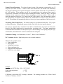
Ice Bin Capacity. Crushed or cylinder ice weighs approximately 35 pounds per cubic ft. (35 lb/ft3 ).
As ice drops into a bin, it will pile up and slope naturally at about a 45° angle. This natural slope
should be taken into account when locating the bin thermostat bulb (or other bin level control) and
when calculating the normal bin capacity. If the ice is spread out by hand in the bin for maximum
storage capacity, make sure a hazard is not created by allowing ice to back up into the chute and
jamming the cutter. Always allow enough room below the chute for at least one harvest (approx. 40
lbs. of ice).
If a two-way defector is installed below the ice chute, care should be taken to make sure it is located
directly in the center of the stream of ice as it falls to give even distribution of the ice.
Refrigeration System (Review Before Starting Machine). The refrigeration system uses HCFC22 refrigerant, a compressor, a thermal expansion valve, a flooded evaporator (freezer), and warm
gas defrost. Following the schematic, you see that during the freeze period of the machine’s cycle,
the compressor discharge gas leaves the compressor and goes to the condenser where it is condensed
into a liquid by the removal of heat by either air or water passing through the condenser. A reservoir
of liquid is accumulated in the receiver and flows as required, passing through the filter/drier, then the
thawing chamber, (a lower separate section of the freezer). The liquid solenoid valve (the “A” valve)
being open during the operation allows the liquid to be metered by the thermal expansion valve that
opens and closes (modulates) as the temperature of the suction line dictates. The evaporator floods
with wet refrigerant that is in contact with the outside of the tubes that the ice-making water is being
circulated through. The heat contained in this water is conducted through the wall of the tubes,
lowering the temperature of the water, causing it to freeze and form a long tube of ice that adheres to
the inside of each of the freezer tubes. The flowing water keeps the accumulated ice clear by washing
separated solids down into the sump area of the water tank.
The wet suction gas leaves the freezer, passes through the accumulator, and has any remaining liquid
droplets removed by the heat contained in the high side liquid passing through the heat exchanger.
The dry gas enters the compressor and is compressed then discharged to the condenser, the
condensed liquid flows through the liquid side of the heat exchanger and to the receiver completing
the cycle.
As the ice is formed in the freezer, the suction pressure steadily reduces until it causes one of the
freezer pressure switches to close and switch the machine to a harvest period.
During the harvest period, the thawing gas solenoid valve, (The “D” valve), is open allowing the
warm high pressure gas to enter the freezer. This heat melts a thin film from the outside of the ice,
reducing the diameter and letting it fall free from the freezer tubes. The flow of thaw gas through the
freezer is controlled by the CPR (crankcase pressure regulator) valve. This valve should be set as
recommended in TABLE 9-2, “CPR Valve Setting”.
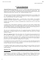
For additional information and familiarization, see “How Your Tube-Ice Machine Works,” Page 4-1,
and Piping Schematics, FIGURES 4-1, 5-7, & 5-3.
10/21/01
HEC-Series Service Manual
5-1
INITIAL START UP AND OPERATION
5. Initial Start-Up & Operation
Start-Up Checklist
Be sure to complete and return the Warranty Registration/Start-Up report located at the front
of the manual.
In order to prepare the machine for start-up, it will be necessary to remove the front panels for access
to the various valves and for observation.
_____ 1.
See that water-inlet connections are attached to the proper couplings (water cooled
units) and to water for ice making. The inlet shutoff valves should be open. The
water level in the water pan should be at a height where the make-up water float valve
will be closed when the machine is idle.
_____ 2.
See that the cutter motor gear reducer is lubricated (see “Lubrication” for
instructions).
_____ 3.
See that compressor crankcase oil level is at proper height of 1/4 to 3/4 of the sight
glass. (no sight glass on Carlyle scroll compressor.)
_____ 4.
See that “Cutter” and “Pump” circuit breakers are in the “On” position.
_____ 5.
See that the “Ice” push button switch is in the “Off” position (Button Out).
_____ 6.
See that the “Clean” push button switch is set to “Off” position (Button Out).
NOTE: All valves are tagged with instructions.
_____ 7.
Open compressor service valves (34 and 35), the two hand-stop valves (90) in the
thawing gas line, (91) in the condenser return line, and the hand-stop valve (58) in the
liquid line and hand-stop valve (69) to the freezer pressure switch. These valves are
tagged to indicate that they were closed for shipping purposes.
_____ 8.
IMPORTANT! CHECK TO SEE that all stop valves in the various refrigerant lines
are open except charging valve (28), according to the attached tags.
_____ 9.
Immediately after opening all valves, entire machine should be checked for
refrigerant leaks with electronic leak detector.
_____ 10.
Close exterior disconnect switch to energize crankcase heater and power the PLC.
! CAUTION !
The crankcase heater should be energized for a MINIMUM of
2 HOURS before attempting to operate the compressor.
! CAUTION !
_____ 11.
10/21/01
Connect a suction gage to the low pressure test connection and a high pressure gage
to the high pressure test connection. After TWO HOURS, push the “Ice” button and
the “Start” button. The machine will not operate until the low pressure raises
sufficiently (to approximately 40 psig) to close the low pressure switch (4PS) & open
the cylinder ice freezer pressure switch (FPS2).
HEC-Series Service Manual
5-2
INITIAL START-UP AND OPERATION
If the machine does not start, put the “Ice” button in the “Off” position. Put the “Clean” button in the
“On” position and push the “Start” button. This will put the machine in the clean mode and tell the
PLC that the machine is pumped down. Now put the “Clean” button in the “Off” position, shutting
off the water pump, and the “Ice” button in the “On” position. When the “Start” button is pushed,
the “A” valve will open and feed liquid for 2 minutes then go to the freeze cycle.
Note: Be sure to check compressor rotation of machines with scroll compressor.
Suction pressure must decrease and discharge pressure increase immediately. To change rotation,
reverse two (2) of the three (3) compressor wires L1, L2, and L3 at the control panel terminal block.
FIGURE 5-1
Solenoid Valves
_____ 12.
When the machine starts, check water level in water pan (7) to determine whether or
not water pump (6) is pumping water. It may be necessary to stop and start the
machine several times to expel air from the water pump impeller housing.
Note: Use one of the circuit breakers, “Cutter” or “Pump” to stop--for approximately 10 seconds-and start button to start the machine, if necessary to prime the pump.
! CAUTION !
If it should ever become necessary to add refrigerant to the
system, charging valve (28) is provided for this purpose.
Be sure to follow all local and federal regulations regarding
the handling of refrigerants and their illegal emission into
the atmosphere.
! CAUTION !
10/21/01
HEC-Series Service Manual
5-3
INITIAL START UP AND OPERATION
Refrigerant Charge. Check the refrigerant level after the machine has operated for a few cycles. It
should be slightly above the operating level, as indicated on the receiver, a few minutes prior to start
of a thawing period. If this level is low at this time, sufficient refrigerant should be added to the
system to raise the level above this point. One inch (1”) is equivalent to 5 lbs. in the receiver. Add
only a small quantity (5 lbs. or less) at a time, and operate the machine several cycles to check the
level before adding additional refrigerant. Refrigerant may be added as a liquid through the charging
valve (28) only while the machine is operating. It is important that no air or other non-condensable
gases enter the system when charging refrigerant into the unit.
When adding refrigerant to the system, it may also be necessary to add lubricating oil.
“Lubrication Compressor”, Section 7, “Maintenance”.
See
In order to check the total charge in the system, it is necessary to transfer all of the refrigerant to the
receiver. A total pumpdown procedure should be performed.
Total Pumpdown Mode. The function of the total pumpdown mode is to transfer all the liquid
refrigerant from the freezer (evaporator) into the receiver. Total pumpdown is initiated as the first
phase of and prior to entering the clean mode. It should only be performed when the freezer is clear
of ice.
Its main purpose is to clear the freezer of liquid refrigerant and prevent possible refrigerant migration
to the compressor while running the clean cycle. It also can be used to check the units total
refrigerant charge.
Total pumpdown is initiated by setting the selector switch to the “Cyl” position, turn “Ice” switch to
the “Off” position (allow the machine to harvest if running in a freeze cycle), press the “Clean” button
to the “On” position. At this time the compressor and water pump will run, the “A” (liquid feed)
solenoid valve will close and the freezer will begin to pump down. As the suction pressure decreases,
the freezer pressure switch will initiate a harvest cycle to clear the partially formed ice cylinders from
the freezer. This harvest cycle will end after one minute and the total pumpdown will resume,
continuing until the compressor cycles off by the low pressure switch. At this time, only the water
pump will be running. The “Clean” push button must then be pushed to the “Off” position and the
machine will go to the standby mode.
To restart the machine after a total pumpdown:
1. Set the selector switch to the position desired (dual ice type machines only).
2. See that the “Clean” switch is in the “Off” position.
3. Push the “Ice” button to the “On” position.
4. Push the “Start” button.
At this time, the “A” (liquid feed) solenoid valve will open for 2 minutes and the machine will start in
a freeze cycle.
! CAUTION !
If the power has been turned off to the machine, make sure the compressor crankcase is warm
and there is no liquid refrigerant in with the oil before restarting the unit.
! CAUTION !
10/21/01
5-4
INITIAL START-UP AND OPERATION
10/21/01
FIGURE 5-2
Piping Schematic, Air-Cooled
HEC-Series Service Manual
HEC-Series Service Manual
10/21/01
FIGURE 5-3
Piping Schematic, Water Cooled
5-5
INITIAL START UP AND OPERATION
HEC-Series Service Manual
6-1
ELECTRICAL CONTROLS & THEIR FUNCTIONS
6. Electrical Controls & Their Functions
Control Panel Parts
*BT1
BT2
C
PLC
*R
TB
SVI
12A 2117G02000000-Bin Thermostat (Crushed)
12A 2117G02000000-Bin Thermostat (Cylinder)
12A 7516E13000000-Compressor Contractor
12A 7518E2000000 - Auxiliary Contact
12A 7536M01000000 - Programmable Controller
12A 7517E18000000 - Reversing Relay
12A 7501E30000000 - Terminal Block Assembly
Service Indicator Switch (part of fuse block assembly)
*FPS1
FPS2
P
CU
FC
FU0-FU5
Fuses (FU0-FU5)
12A 2117E04000000-Freezer Pressure Switch (Crushed)
12A 2117E04000000-Freezer Pressure Switch (Cylinder)
12A 7516E09000000-Pump Contactor
12A 7516E09000000 - Cutter Contactor
12A 7516E11000000 Fan Contactor (Air-cooled only)
PLC Protection Fuses (part of fuse block assembly)
12A 7504E23000000 - 2 amp fuses
*Note: Components used in dual ice type machines only
FIGURE 6-1
Control Panel (Cover Removed)
10/21/01
HEC-Series Service Manual
6-2
ELECTRICAL CONTROLS & THEIR FUNCTIONS
Description of Control Panel Parts.
*BT1 and BT2. Bin Thermostats. Ice bin thermostats for automatically stopping and starting the
machine based on the ice level in the storage bin. BT1 (Crushed Ice). BT2 (Cylinder Ice).
C. Compressor Motor Contactor. Provides power to the compressor motor. Energized during
freezing and thawing. Normally closed contact provides power to the compressor crankcase heater
when the machine is off.
P. Pump Contactor. For making and breaking contacts to start and stop the circulating water
pump. Energized during the freeze, pumpdown, and clean modes.
CU. Cutter Contactor. For making and breaking contacts to start and stop the cutter. Energized
during the harvest mode.
PLC. Programmable Logic Controller. For monitoring, sequencing, and controlling various
functions of the Tube-Ice® operation. Also has a built in thaw timer for controlling the time of the
thawing period. Thawing time is adjustable from 1 1/2 to 5 minutes.
*FPS1 and FPS2. Freezer Pressure Switches. For regulating the ice thickness by sensing the
freezer pressure and initiating the thaw period. FPS1 (Crushed Ice). FPS2 (Cylinder Ice).
*R. Reversing Relay. Switches machine to either cylinder or crushed ice by making or breaking
various circuits concerning cylinder or crushed ice production. Energized during crushed ice
production only.
FC. Fan Contactor. Cycles the fan motor(s) of air-cooled condenser “On” and “Off”. Activated by
the condenser pressure switch. (Air-cooled machines only).
SVI. Service Indicator Switch. For disabling the machine and entering a troubleshoot mode to
identify a machine “fault”. Opened for entering a troubleshoot mode, closed for normal machine
operation.
FU0 through FU5. Overload and short circuit protection of the components controlled by the PLC
output. See Wiring Schematics.
CD-OL. Compressor Motor Overload. HEC-30 and HEC-40 only. Stops the machine in the
event of a mechanical or electrical malfunction of the compressor motor, causing excessive amperage.
Is automatically reset, but the machine must be manually restarted by the “Start” push button or will
automatically restart after two hours.
CD-TS. Compressor Motor Thermal Overload. HEC-30 and HEC-40 only. Stops the machine in
the event of excessive temperature in the compressor motor windings. Will reset when motor cools
sufficiently. The machine can be manually restarted by the “Start” push button or will restart
automatically after the compressor stops when this overload trips and restarts. The machine will stop
by long freeze cycle “fault” after repeated overload trips.
HEC-10 and HEC-20 have built in motor overload protection with automatic reset.
*Note: Components used in dual ice type machines only.
10/21/01
HEC-Series Service Manual
6-3
ELECTRICAL CONTROLS & THEIR FUNCTIONS
Switch Box Parts
FU100
FU200
PBL1
PBL2
PB1
PB2
*SS
S1
S2
*1LT
*2LT
3LT
4LT
12A 7504E10000000
12A 7504E10000000
12A 7500E36000000
12A 7500E36000000
12A 7500E03000000
12A 7500E02000000
12A 7500E07000000
12A 7515E01000000
12A 7515E07000000
12A 7520E10000000
12A 7520E10000000
12A 7520E09000000
12A 7520E09000000
Fuse 2.5 amp
Fuse 2.5 amp
Clean Lighted Push Switch
On/Off Lighted Push Switch
Start Push Button
Manual Harvest Push Switch
Selector Switch
Cutter Overload Switch
Pump Overload Switch
Cylinder Light
Crushed Light
Cutter Overload Light
Pump Overload Light
*Note: Components used in dual ice type machines only.
FIGURE 6-2
Switch Box. Most functions of the machine can be controlled from the switch box.
10/21/01
HEC-Series Service Manual
6-4
ELECTRICAL CONTROLS & THEIR FUNCTIONS
FU100 and FU200, 2.5 Amp Fuses. Overload and short circuit protection for crankcase heater and
the control circuit.
PB1, Start Push Button. For starting the machine in the ice making mode. (Momentary contact).
Will also bypass the built in 120 minute start-up mode. Will also terminate a harvest mode.
PB2, Manual Harvest Push Button. Initiates a thaw period immediately when manually depressed.
(Momentary contact)
PBL1, Clean/Off Lighted Push Button. “Clean” illuminated in the “On” position (button in). Not
illuminated in the “Off” position (button out) for ice making.
PBL2, Ice/Off Lighted Push Switch. “Ice” illuminated in the “On” position (button in) for ice
making. Not illuminated in the “Off” position (button out).
*1 LT, Crushed Light. “Cru” illuminated when set to produce crushed ice.
*2 LT, Cylinder Light. “Cyl” illuminated when set to produce cylinder ice.
Both 1 LT and 2 LT are illuminated when selector switch set in “Auto” position.
3 LT, Cutter Overload. Illuminated when cutter overload switch (S1) has tripped.
4 LT, Pump Overload. Illuminated when pump overload switch (S2) has tripped.
*SS, Selector Switch. For the purpose of selecting the type of ice to be made, either crushed (Cru)
or cylinder (Cyl). Note: Use “Auto” position only when using divided bin.
S1, Cutter Overload Switch. Stops machine operation in the event of a mechanical or electrical
malfunction of the cutter motor, resulting in excessive motor amperes.
S2, Pump Overload Switch. Stops machine operation in the event of a mechanical or electrical
malfunction of the pump motor, resulting in excessive motor amperes.
If machine is turned off by either S1 or S2, the machine stops immediately and advances to the startup mode when the switch is put back in the “On” position. The machine will automatically restart
after two hours in the start-up mode if the switch has been reset. The machine can be restarted also
by resetting the overload switch and pushing the “Start” button. It will restart in a freeze cycle.
*Note: Components used in dual ice type machines only.
10/21/01
HEC-Series Service Manual
6-5
ELECTRICAL CONTROLS & THEIR FUNCTIONS
PLC Features & Functions
(Condensed Description)
The PLC provides many beneficial features as follows:
1.
2.
3.
4.
5.
6.
7.
8.
10/21/01
Identifies machines faults and stores the identity of the last fault.
Automated total pump down prior to a clean mode.
Performs partial pump down when machine cycles off by “Bin Stat” or “Ice” switch.
Provides fault identification:
a. Short cycle fault
b. Long freeze cycle fault
c. High/low pressure fault during freeze
d. High/low pressure fault during thaw
e. High/low pressure fault during partial pump down
f. High/low pressure fault during total pump down
Automatic (2-hour delayed) restart after being off from:
a. Power failure
b. Power interruption
c. Compressor overload cutout
d. Low pressure fault
e. Long freeze fault
f. Short cycle fault
Built in adjustable thaw timer (range 1 1/2-5 minutes).
Closes “A” (liquid feed) solenoid valve and stops the water pump seven seconds before the
harvest begins providing a slight pump out of the freezer and accumulator and allowing the water
level to stabilize before the cutter turns.
Sequences the machine functions to assure the highest product capacity with the least amount of
personal attention.
HEC-Series Service Manual
6-6
ELECTRICAL CONTROLS & THEIR FUNCTIONS
FIGURE 6-3
Control Sequence Flow Chart
10/21/01
HEC-Series Service Manual
6-7
ELECTRICAL CONTROLS & THEIR FUNCTIONS
“PLC” (Programmable Logic Controller)
Sequence Of Controller & Machine Operation
Explanation. The HEC-Series Tube-Ice® machine is controlled by a PLC (Programmable Logic
Controller). The PLC controls the sequence of events and monitors the ice machine functions. The
operational sequences of the HEC-Series Tube-Ice® machine can be best described as a series of eight
different modes. Each mode identifies and defines a sequence of events that occur while in that mode
and thereby cause it to move to the next mode. Only one mode is active at a time. Refer to the PLC
Flow Chart (FIGURE 6-3) in this section for sequencing and various mode paths.
Start-Up Mode. The start-up mode is a function which prevents the premature automatic starting of
the machine at the time of installation, after a power interruption, or after a safety trip. Its normal
time period is two hours.
Initiated by the following:
1. Initial power up at the time of installation
2. Power restored after a power interruption or power failure
3. After running a “Troubleshoot” mode
4. After running a “Clean” mode
5. After running a “Total Pumpdown” mode
6. Machine faults such as:
a) Cutter overload trip (manual reset)
b) Pump overload trip (manual reset)
c) High pressure cutout trip (manual reset)
d) Control circuit fuse failure (manual replacement)
e) Compressor overload trip (automatic reset) - HEC-30 & 40 only
f) Low pressure cutout trip (automatic reset)
7. If both the “Clean” and “Ice” buttons are in the “On” position (and the harvest cycle is complete).
If all safeties in the control circuit are closed, the machine will remain in the start-up mode for a
period of two hours (120 minutes) before automatically advancing to the standby mode. The start-up
mode may be bypassed at any time by pressing the “Start” button to immediately advance to the
standby mode. Make sure the compressor crankcase is warm and there is no liquid refrigerant in with
the oil before pushing the “Start” button.
10/21/01
HEC-Series Service Manual
6-8
ELECTRICAL CONTROLS & THEIR FUNCTIONS
Standby Mode. The standby mode is a decision making mode. It monitors the position of all the
various switches in the control circuitry and at the proper time decides which mode to advance to
next.
Initiated by the following action:
1. After the two hour period in the start-up mode.
2. After pushing the “Start” button.
3. After pushing the “Ice” button to the “Off” (and the harvest cycle and partial pumpdown cycles
are complete).
4. After the bin thermostat contact opens (and the harvest cycle and partial pumpdown cycles are
complete).
Freeze Mode (Freeze Cycle). The freeze mode is active during the normal ice making cycle. During
this time, the circulating water pump and compressor are running and the “A” (liquid feed) solenoid
valve and “X” solenoid valve compressor discharge (AC units only) are open.
Initiated by the following:
1. After the start-up and standby modes are satisfied in sequence.
2. At the termination of the harvest mode.
Harvest Mode (Thaw Cycle). The harvest mode is normally initiated at the termination of the freeze
mode. At this time, the circulating water pump stops and the “A” (liquid feed) solenoid valve closes
for a time period of seven seconds. After seven seconds, the “D” (thaw gas) solenoid valve opens,
the cutter motor starts and the thaw timer is activated.
Initiated by the following:
1. Action of the freezer pressure switch.
2. Pushing the manual harvest button.
The harvest mode is terminated by the thaw (harvest) timer at which time the machine will begin
another freeze cycle. If the “Ice” switch is “Off” or the bin thermostat is satisfied the machine will
advance through the partial pumpdown mode then standby. The harvest mode can be terminated
manually by pushing in the “Start” button. The machine will end the harvest and start a freeze or go
to standby if the “Ice” switch is “Off”.
10/21/01
HEC-Series Service Manual
6-9
ELECTRICAL CONTROLS & THEIR FUNCTIONS
Partial Pumpdown Mode. The partial pumpdown modes precedes the normal off or standby mode.
Its purpose is to transfer a portion of the liquid from the suction accumulator and freezer into the
receiver prior to shutdown of the machine (standby mode). This will discourage any migration of
liquid refrigerant to the compressor during the off or standby mode. It is also intended to help
prevent any liquid refrigerant slugging to the compressor when the machine restarts in a freeze mode.
When partial pumpdown is initiated, the “A” (liquid feed) solenoid valve is closed and the water
pump and compressor run for a set time. After this set time the compressor stops and the machine is
in the standby mode.
Model
Time
HEC-10
7 minutes
HEC-20
7 minutes
HEC-30
5 minutes
HEC-40
3 minutes
TABLE 6-1
Partial Pumpdown Time
NOTE: The PLC uses the cylinder ice pressure switch (FPS2) as a partial pumpdown safety. Do not
remove this pressure switch from the machine.
Initiated by the following:
1. At the end of a harvest cycle with the bin thermostat satisfied.
2. At the end of a harvest cycle with the “Ice” switch in the “Off” position.
Total Pumpdown Mode. The function of the total pumpdown mode is to transfer all the liquid
refrigerant from the freezer (evaporator) into the receiver. Total pumpdown is initiated as the first
phase of and prior to entering the “Clean” mode.
Its main purpose is to clear the freezer of liquid refrigerant and prevent possible refrigerant migration
to the compressor while running the “Clean” cycle. It can also be used to check the units total
refrigerant charge, isolate the refrigerant in the receiver while making repairs, or prepare the machine
for disconnecting and moving.
Initiated by the following:
1. Set the “Selector” switch to the “Cyl” position (dual ice type machines only).
2. Turn the “Ice” switch to the “Off” position (allow the machine to harvest if it is operating).
3. Push the “Clean” button into the “On” position. At this time the compressor and water pump will
run, the “A” (liquid feed) solenoid valve will close and the freezer will begin to pumpdown. As
the suction pressure decreases, the freezer pressure switch will initiate a harvest cycle to clear the
partially formed ice cylinders from the freezer. This harvest cycle will end after one minute and
the total pumpdown will resume continuing until the compressor cycles off by the low pressure
switch. At this time, only the water pump will be running. The “Clean” button must then be
pushed to the “Off” position and the machine will be in the standby mode.
To restart the machine after a total pumpdown:
10/21/01
HEC-Series Service Manual
6-10
ELECTRICAL CONTROLS & THEIR FUNCTIONS
1.
2.
3.
4.
Set the “Ice Selector” switch to the position desired.
See that the “Clean” switch is in the “Off” position.
Push the “Ice” button to the “On” position.
Push the “Start” button. (Make sure the compressor crankcase is warm and there is no liquid
refrigerant in with the oil before pushing the “Start” button.)
At this time the “A” (liquid feed) solenoid valve will open for two minutes, allowing the freezer
pressure to raise to the cut-in setting of the low pressure switch. Then the machine will start in a
freeze cycle.
Clean Mode. The “Clean” mode is considered to be a maintenance or servicing function of the
machine. It should only be initiated when the freezer is clear of ice.
The first phase of the “Clean” mode is a total pumpdown.
! CAUTION !
Do not attempt to bypass the total pumpdown phase of the “Clean” mode. If a clean cycle is
performed without first completing a total pumpdown, the warm water being circulated
through the freezer tubes can force refrigerant to migrate to the suction accumulator and
compressor. This could create an unfavorable condition and possible cause damage to the
compressor when returning to the freeze mode.
! CAUTION !
After the total pumpdown and pushing the “Start” button, the water pump can be started and stopped
by simply pushing the “Clean” button on and off. (Note: If the freezer and compressor suction
pressure have come up enough to open the freezer pressure switch FPS2 and close low pressure
safety switch 4PS, the compressor will come and on and pump down the freezer again.) Ice machine
cleaning solution can be circulated though the tubes to accomplish the cleaning procedure. If the
water pump is left to run in the clean mode. The clean mode can be resumed by pushing the “Start”
button.
At the termination of the clean mode, the machine can be returned to ice making mode by pushing the
“Clean” button to the “Off” position; the “Ice” button to the “On” position; and the “Start” button.
See “Maintenance--Ice Making”, Section 7, for complete cleaning procedure.
Troubleshoot Mode. If the machine has stopped due to a “fault” during normal operation, a
troubleshoot mode can be used to identify this “fault”. This mode can be entered from a start-up or
standby mode.
To enter the troubleshoot mode, the SVI (service indicator) switch located inside the control panel
(FIGURE 6-1) must be opened. This will disable the machine and its components.
10/21/01
HEC-Series Service Manual
6-11
ELECTRICAL CONTROLS & THEIR FUNCTIONS
Initiated by the following:
1. Open the SVI switch.
2. Set the “Clean” button to the “On” position.
3. Set the “Ice” button to the “On” position.
4. Push both the “Harvest” and “Start” buttons simultaneously.
At this point, the machine “fault” can be identified and necessary corrections or adjustments can be
made for returning the machine to good working order. A “fault” will be identified by illumination of
specific numbered PLC output indicator lights on the PLC. See “Fault Identity”, TABLE 6-2.
To exit the troubleshoot mode, follow this sequence:
1. Set the “Clean” button to the “Off” position.
2. Set the “Ice” button to the “Off” position.
3. Close the SVI switch.
4. This will return the machine to the “Start-Up” mode.
Output Light
ll¬l¬l
ll¬l¬¬
ll¬¬ll
ll¬¬l¬
ll¬¬¬l
Fault #
#10
#11
#12
#13
#14
ll¬¬¬¬
#15
l¬llll
#16
Fault Description
High or low pressure cutout during freeze cycle
High or low pressure cutout during harvest cycle
High or low pressure cutout during partial pumpdown
High or low pressure cutout during total pumpdown
Short Cycle Fault:
Three Harvests Within A Specified Time As Noted:
HEC-10 --- 10 Minutes
HEC-20 --- 10 Minutes
HEC-30 --- 5 Minutes
HEC-40 --- 5 Minutes
Long Freeze Cycle Fault:
One Freeze Cycle Longer Than A Specified Time As Noted:
HEC-10 --- 120 Minutes
HEC-20 --- 120 Minutes
HEC-30 --- 80 Minutes
HEC-40 --- 60 Minutes
Power failure/compressor O/L
Note: ¬ indicates light is “On”
TABLE 6-2
Fault Identity
10/21/01
HEC-Series Service Manual
6-12
ELECTRICAL CONTROLS & THEIR FUNCTIONS
NOTE: Part #12A-7536M01000000. PLC must be pre-programmed for specific model.
FIGURE 6-4
PLC Display
Input
0
1
2
3
4
5
6
7
Description
Cylinder Ice Bin Stat / Selector Switch
Crushed Ice Bin Stat / Selector Switch
Freezer Pressure Switch / Manual Harvest
Start Switch
Clean Switch
Ice Switch
High / Low Pressure Safety Switch
Service Indicator Switch
Output
0
1
2
3
4
5
Description
Flush Valve (Special Order Only)
A-valve
Compressor (X-valve / air cooled machine)
Reversing Relay
Water Pump
Cutter / D-valve
TABLE 6-3
PLC Inputs & Outputs
10/21/01
HEC-Series Service Manual
6-13
ELECTRICAL CONTROLS & THEIR FUNCTIONS
In
0
1
S10 - Start
2 3 4 5
6
7
In
¢ ¢ ¢ ¢ ¢ l l l
Out
0
1
2
3
4
0
1
S11 - Standby
2 3 4 5
5
Out
¢ ¢ ¢ ¢ ¢ ¢
7
0
1
2
3
4
5
¢ ¢ ¢ ¢ ¢ ¢
Note: Inputs # 0 or # 1 may be “on”. If machine has shut off due
to a High pressure fault, input 6 will be “off”.
Note: If Ice button, Input # 5 is “off”, Input # 0 or # 1 may be
“on”.
S12 - Freeze (Cylinder Ice)
0 1 2 3 4 5 6
S12 - Freeze (Crushed Ice - 5 minutes into freeze)
In 0 1 2 3 4 5 6 7
In
7
l ¢ ¢ ¢ ¢ l l l
Out 0
1
2
3
4
¢ l ¢ ¢ ¢ l l l
5
Out
¢ l l ¢ l ¢
In
S13 - Harvest (Cylinder Ice)
0 1 2 3 4 5 6
7
2
3
4
5
In
S13 - Harvest (Crushed Ice)
0 1 2 3 4 5 6
7
l ¢ ¢ ¢ ¢ l l l
¢ l ¢ ¢ ¢ l l l
Out 0
Out 0
1
2
3
4
5
S14 - Partial Pumpdown
0 1 2 3 4 5 6
1
2
3
4
7
In
0
5
S16 - Clean
2 3 4 5
6
1
2
3
4
5
7
1
2
3
4
5
¢ ¢ l ¢ l ¢
7
l l l ¢ l ¢ ¢ l
Out 0
4
S15 - Total Pumpdown
1 2 3 4 5 6
Out 0
Note: If Ice button, Input # 5 is “off”, Input # 0 or # 1 may be
“on”.
1
3
l l ¢ ¢ l ¢ l l
¢ ¢ l ¢ l ¢
0
2
Note: Input # 2 will be “on” at the start of the Harvest, but will
turn “off” as thaw gas pressure rises.
¢ ¢ ¢ ¢ ¢ l l l
Out 0
1
¢ ¢ l l ¢ l
Note: Input # 2 will be “on” at the start of the Harvest, but will
turn “off” as thaw gas pressure rises.
In
1
Note: Input # 2 will come “on” to initiate the harvest.
¢ ¢ l ¢ ¢ l
In
0
¢ l l l l ¢
Note: Input # 2 will come “on” to initiate the harvest cycle.
Note: Input # 0 and # 1 may be “off”.
In
0
S17 - Troubleshoot
1 2 3 4 5 6
7
¢ ¢ ¢ ¢ l l l ¢
5
Out 0
¢ ¢ ¢ ¢ l ¢
1
2
3
4
5
¢ ¢ ¢ ¢ ¢ ¢
Note: As pressure builds in the freezer and at the compressor,
Input # 2 may turn “off” and Input # 6 turn “on”.
Note: Input’s # 0 and # 1 may be “on”.
Output lights will indicate the previous machine fault.
FIGURE 6-5
PLC Input/Output Display
10/21/01
6
¢ ¢ ¢ ¢ ¢ l l l
HEC-Series Service Manual
6-14
ELECTRICAL CONTROLS & THEIR FUNCTIONS
Use Copper Conductors Only. Protected against primary single phase failure.
FIGURE 6-6
Dual Ice Type--Machine Off
10/21/01
HEC-Series Service Manual
6-15
ELECTRICAL CONTROLS & THEIR FUNCTIONS
Use Copper Conductors Only. Protected against primary single phase failure.
FIGURE 6-6A
Single Ice Type--Machine Off
10/21/01
HEC-Series Service Manual
6-16
ELECTRICAL CONTROLS & THEIR FUNCTIONS
Use Copper Conductors Only. Protected against primary single phase failure.
FIGURE 6-7
Dual Ice Type--Freeze Cycle (Cylinder Ice)
10/21/01
HEC-Series Service Manual
6-17
ELECTRICAL CONTROLS & THEIR FUNCTIONS
Use Copper Conductors Only. Protected against primary single phase failure.
FIGURE 6-7A
Single Ice Type--Freeze Cycle
10/21/01
HEC-Series Service Manual
6-18
ELECTRICAL CONTROLS & THEIR FUNCTIONS
Use Copper Conductors Only. Protected against primary single phase failure.
FIGURE 6-8
Dual Ice Type--Harvest Cycle (Cylinder Ice)
10/21/01
HEC-Series Service Manual
6-19
ELECTRICAL CONTROLS & THEIR FUNCTIONS
Use Copper Conductors Only. Protected against primary single phase failure.
FIGURE 6-8A
Single Ice Type--Harvest Cycle
10/21/01
HEC-Series Service Manual
6-20
ELECTRICAL CONTROLS & THEIR FUNCTIONS
Use Copper Conductors Only. Protected against primary single phase failure.
FIGURE 6-9
Dual Ice Type--Clean Cycle (A Maintenance Operation)
10/21/01
HEC-Series Service Manual
6-21
ELECTRICAL CONTROLS & THEIR FUNCTIONS
Use Copper Conductors Only. Protected against primary single phase failure.
FIGURE 6-9A
Single Ice Type--Clean Cycle
10/21/01
HEC-Series Service Manual
7-1
MAINTENANCE
7. Maintenance
Ice-making Section. The ice-making section of the Tube-Ice® machine should be cleaned at least
twice a year (more often if water conditions cause mineral build-up) using an approved food-grade ice
machine cleaner. The water pump is used to circulate the cleaner through the system by setting the
“Clean” push button switch to the “On” position (button in) and starting and stopping the pump by
this push button switch and the start button. For complete instructions, refer to the “Cleaning
Procedure” attached to the equipment and duplicated here.
Cleaning Procedure
1. Set “Ice” switch to “Off” position. If the machine is running, it will shut down on the completion
of the harvest period and partial pumpdown cycle. Remove the freezer cover to inspect and clean
the water distributors as necessary. Replace the freezer cover with the distributors installed.
2. Remove ice from storage area or cover opening to prevent ice contamination.
3. Set the “Selector” switch to “Cyl” position (dual ice type machines only).
4. Push the “Clean” button to the “On” position. The machine will begin a total pumpdown. After
total pumpdown, the compressor will stop and only the water pump will be running.
5. Push the “Clean” button to the “Off” position and the pump will stop.
6. Shut off the water supply and drain the water tank flushing loose scale in the process.
7. Close the water tank drain valve and fill tank with approximately six gallons of tap water. Warm
water can be used but should not exceed 115°F (46°C).
8. Add a measured portion of a food-grade ice machine cleaner (nickel safe preferred) to the water
tank in accordance with cleaner instructions and insert the plastic tubing and petcock valve
(discharge end) of the adjustable blowdown into the water tank and adjust the petcock to full
open.
9. Push the “Clean” button to the “On” position and push the “Start” button to run the pump only
and circulate cleaner solution. Clean until deposits are dissolved by changing solution as
necessary.
10. When the system is considered clean, stop the pump, drain the tank, turn on the water supply, and
flush the system thoroughly with clean water (at least twice) as necessary to remove chemical
residue.
11. Clean inside the ice storage area and remove any solution that may have entered during the
cleaning process. Remove cover from over the opening into the storage area.
10/21/01
HEC-Series Service Manual
7-2
MAINTENANCE
12. Make sure the water tank drain valve is closed, the adjustable blowdown petcock is adjusted
properly, the adjustable blowdown tubing is inserted into the drain bypass line, the “Clean” button
is in the “Off” position, and the selector switch is in the desired ice making position.
13. Push the “Ice” button to the “On” position and push the “Start” button for immediate start-up in
the ice production mode.
Water Distributors. The water distributors are located under the freezer cover (8) at the top of the
freezer. There are 78 distributors used in the models having an “S” suffix (i.e., Models HEC-10S,
HEC-20S, HEC-30S, and HEC-40S); 48 distributors are used in the models having an “M” suffix
(i.e., Models HEC-10M, HEC-20M, HEC-30M, and HEC-40M). These distributors may require
occasional or periodic cleaning to remove solids and foreign particles accumulated from the make-up
water. The frequency of this cleaning operation will depend on the characteristics of the water
supply.
The cleaning operation is indicated when the inside diameter of a large proportion of the ice becomes
irregular (due to channeling of water), or if some of the ice is opaque, or if there is a noticeable
decrease in ice capacity.
To clean distributors, stop the unit and remove the freezer cover (8) on top of the freezer. The water
distributors (one in each tube) may then be removed with pliers for cleaning. Grasp the top of the
distributor gently with pliers, twist, and pull up to remove the distributor. After cleaning, reinstall
distributors firmly in each tube.
Water Tank. The production of opaque ice usually indicates that the water in the water tank
contains a concentrated amount of solids or salts or the adjustable blowdown is not opened enough.
See “Adjustable Blowdown”, Section 9.
Remove cover plate. Open drain valve (39). Clean tank thoroughly by flushing out with a hose and
scrubbing with a stiff brush. Fill the water tank with fresh water.
When restarting the machine, be sure that the water pump is circulating water. It is possible that air
may have collected in the pump impeller housing and the pump may have to be stopped and started
several times to expel the air. This procedure can be done by use of “Pump” or “Cutter” circuit
breaker switches and “Start” push button.
Drip Pan. If the machine is installed on a bin with a drip pan, it is important to keep the drip pan free
of any foreign materials and to keep the drain for this pan open. This drain must not run through the
ice compartment of the bin.
Water Cooled Condensers. Checking operation. How often condensers need cleaning depends on
so many variables that it is impossible to recommend a schedule. Some will seldom need cleaning,
other perhaps need cleaning once a year. In rare cases, cleaning is required several times a year.
10/21/01
HEC-Series Service Manual
7-3
MAINTENANCE
Proper operation of cooling towers will increase the interval between cleaning considerably. The
tower overflow rate should be checked frequently. If a tower is operated with insufficient overflow,
nominal 1-1/2 to 3 GPH bleed depending on water quality, the resulting mineral concentration in the
water can cause rapid and heavy flooding inside the condenser tubes, requiring excessively frequent
cleaning. Also, these conditions often lead to severe corrosion.
Chemical additives, including those to stop algae and related growths, should be obtained only from a
reputable, established supplier, and used specifically according to directions. Excessive treatment of
the water can cause more harm than good: and the condensers, pumps, piping, and the towers
themselves may be damaged.
It is advisable to double check the system to make sure that fouling is actually causing the trouble.
High head pressure alone does not mean a fouled condenser. The following possibilities should
always be checked before cleaning is undertaken:
1. Non-condensables in system or faulty head pressure gauge? Check standby pressures against
refrigerant tables.
2. Incorrectly set or defective water regulator valve? Check its setting and operation.
3. Partly closed compressor discharge service valve? Check its setting. Stem should be backseated.
4. High water temperatures entering condenser? Check tower fan and system.
After the above possibilities have been eliminated, determine the temperature difference between the
water leaving the condenser and the refrigerant condensing temperature (saturation temperature, from
pressure-temperature chart, corresponding to head pressure). If this difference is more than 10°F,
cleaning is indicated because this difference indicates a good heat exchange is not being made. If this
difference is less than 8°F, something other than a fouled condenser may be causing the high head
pressure. In normal operation, this difference will stay between 5°F and 10°F regardless of water
inlet temperature when the water flow is regulated by a pressure operated water valve. If this
difference is less than 5°F, restricted water flow or a low supply pressure is indicated. A restriction
can occur with foreign matter in the condenser, but it is also likely to be somewhere else in the
system.
Draining. Draining of water cooled condensers is recommended in preparation for the winter cold
where units may be left exposed to ambients below 32°F. Theoretically, it is easy to drain a
condenser. In practice, the problem can be complex.
Despite the fact that a condenser my have vent and drain fittings, the opening of these fittings is not
sufficient for a natural gravity flow. Water will be retained in a tube due to (1) surface tension and
(2) the normal curvature between tube supports. Our experience shows that as much as 20% of the
water in the condenser can be retained. To break the surface tension on the tubes and to drain all
tubes completely, it is necessary to remove the back plate and actually tilt the condenser a minimum
of 5 degrees. Whether water left in the tubes will cause damage during a freeze-up will be dependent
upon how quickly the freeze occurs and the location of the water inside the condenser.
In the field it is recommended that the tubes be blown out individually with air. Alternatively, a
minimum of 25% ethylene glycol in the system will also prevent a freeze which can rupture the tubes.
10/21/01
HEC-Series Service Manual
7-4
MAINTENANCE
Chemical Cleaning. The Henry Vogt Machine Co. makes no recommendation for any particular
chemical preparation. The same chemical may not be effective for all situations.
! CAUTION !
The following directions and precautions should be observed
when cleaning is undertaken. The warranty on condensers is void if
they are damaged by improper cleaning tools or methods. If
harsh chemicals are used, be sure to follow the manufacturer’s
recommendations regarding safety in handling those solutions.
! CAUTION !
a) Use only preparations from an established, reliable source.
b) Follow directions exactly, particularly regarding amounts to use, and flushing or neutralizing
procedure after cleaning.
c) Close the water supply stop valve. Remove the condenser water regulating valve (41).
d) Circulate the solution through the condenser until it is considered clean.
e) Flush the condenser according to directions.
f) Install the water regulating valve and connecting piping.
Open the water supply stop valve and check for leaks.
Mechanical cleaning.
Part I.
a) Close the stop valve in the water supply line.
b) Drain the water from the condenser.
c) Remove water regulating valve (41) and attached piping to the condenser.
d) Remove the cover plate on the side of the frame to expose the condenser end plate.
e) Remove the nuts, water plates, and gaskets from both ends of the condenser. If the gasket does
not lift off with the end plate, do not try to pry it off. The seal surface may be damaged, which
would cause a water leak. To free a sticking gasket, replace the water plate and tap it on the
outside face with a mallet or a block of wood. After a few taps, the gasket will spring free and
will then slip off with the water end plate.
f) Gaskets need only be rinsed in running water: rust, scale or dirt will not stick to gasket material.
A rag or soft brush is all that is required to remove any foreign matter.
Part II.
The inside of the water end plates and the outer tube sheet surfaces should be cleaned only with clear
water and a rag or a soft bristle brush. A worn paint brush is excellent.
These surfaces have been coated with a special material which will give years of protection against
corrosion unless damaged. Never use a wire brush or a strong caustic on these surfaces.
10/21/01
HEC-Series Service Manual
7-5
MAINTENANCE
Flush condenser tubes clear with air, water, or a piece of rag on a stick or wire. In many cases this is
all that is required. If the inside surfaces are smooth, even though discolored, further cleaning is not
necessary. It is useless to try and get a bright copper surface on the inside of the tubes. They will
discolor almost immediately in service and the condenser has been designed with an adequate reserve
for moderate fouling on these surfaces.
If, however, a rough coating remains inside the tubes after flushing and wiping, further cleaning is
desirable. The color of this coating varies with water conditions, but roughness indicates cleaning
tools should be used.
Any type tool to be considered should be tried first on a piece of copper tubing held in a vise or flare
block. Nylon, brass, or copper brushes are recommended. If any flakes of copper appear or if score
marks are made inside the tube, the tool should not be used. Never use anything with sharp or rigid
edges which could cut into the copper tubing.
A cleaning tool is available from Vogt through your distributor. Ask for Part #12A-2055B01.
When using a cleaning tool, keep the inside of the tube wet and move the tool slowly from one end to
the other while rotating it at a moderate speed. A hand drill brace is recommended. If an electric drill
is used, a low speed attachment on a 1/4” size drill is preferred. Larger units are powerful enough to
damage a tube, if for any reason, the cleaning tool should stick. After one or two passes in each tube,
they should be flushed and inspected. Often this is enough, although some deposits require more. In
any case, stop when a few places begin to show a copper color.
After cleaning, wipe all foreign matter from the tube sheets and studs. Reassemble as outlined on
gasket installation instructions.
If the gasket seal ridge was damaged and a replacement is not immediately available, water leaks can
be stopped by removing the gasket, drying it, and apply a thin film of a non-hardening gasket sealer,
such as Permatex #2, around the seal ridge. This film should be no thicker than the height of the
ridge itself and about 3/16” wide. Then re-assemble.
If a new gasket is put on later, be sure to remove any grit or particles that stick to the sealer film on
the tube sheet. It is not necessary to remove all traces of the sealer before installing a new gasket, as
long as no particles that cut into the new gasket remain on the surface.
Air-Cooled Condenser Cleaning. Visual inspection will indicate if dirt is accumulating and clogging
the fin face of the condenser. A vacuum cleaner, compressed air, or a brush may be used to remove
any accumulation of loose direct from the fin section of the condenser.
For the removal of more severe accumulations of dirt or foreign materials, a detergent-type cleaner
can be used. This cleaning agent can be supplied by your local refrigeration supply house. Follow the
manufacturer’s instructions when using a liquid cleaner.
If fins have been damaged, they should be straightened with the proper fin comb.
10/21/01
HEC-Series Service Manual
7-6
MAINTENANCE
Lubrication
Compressor. In starting and charging the unit, the oil sight glass (33) in the crankcase of the
compressor should be watched carefully for the first hour to make certain the proper lubrication is
being maintained. The oil may become low in the crankcase on an initial start-up if the electrical
current has been interrupted to the machine, thus de-energizing the compressor crankcase heater.
Before starting the machine again, the heater should be energized for a time period of at least two
hours to evaporate refrigerant that may have condensed in the crankcase during the shutdown period.
If level is low after start-up, it should begin to return after a short period of operation.
The oil level should be checked frequently, particularly during the start-up operation, to see that a
sufficient amount of oil remains in the crankcase. While it is important to observe the oil splash
during operation, the true level can be obtained only when the compressor is stopped. With the
compressor idle, the oil level should be at a height of 1/4 to 1/2 of the sight glass but never out of
sight above it.
Although the machine was shipped with the oil charge, which was originally added for the test
operation, it may be necessary to add some oil when or if new refrigerant is added to the system.
An oil pump should be used to force any oil that may be required into the system. Oil may be added
to the compressor of all units through the low pressure test connection adjacent to the high/low
pressure switch or through the compressor suction service valve. The compressor suction service
valve should be “backseated” to shut off pressure to the gauge port when connecting the oil pump.
Air should be purged from the oil pump discharge line by forcing some oil through the line before
tightening the charging connection.
For HEC-10, HEC-20 (with Copeland scroll), HEC-30, and HEC-40 use “Dual Inhibited Sunisco
3GS” (Viscosity 150) or equal. Do not use a synthetic substitute.
For HEC-20 with Carlyle
Scroll compressor use Zerol 150 oil.
Cutter Gear Reducer. The oil level for the gear reducer should be checked if there is evidence of a
leak. It should be level with the plugged opening in the side of the gear housing. Use Mobile 600W
cylinder oil or equal. Change oil once a year.
10/21/01
HEC-Series Service Manual
7-7
MAINTENANCE
Preventive Maintenance
For The Manager Who Depends Upon This Machine
For Efficient Operation.
“Preventive Maintenance” simply means that you or a delegated employee makes a daily visual check
of your Tube-Ice® machine. Here is what to look for and why:
Daily checklist:
1. Is the machine running or is the bin full
2. Bin doors kept closed
3. Thermostat bulb in bracket
4. Ice quality (clarity and uniformity)
5. Does all ice discharge during harvest
6. Cleanliness
7. Unusual noises
Why? When you make these simple observations on a daily basis, you insure the smooth production
of ice for your facility. When you are aware of the proper operating conditions and observe them on
a daily basis, changes in these conditions can alert you to changes in the operation of the machine
which may require maintenance--long before a service situation arises.
“An ounce of prevention is worth a pound of cure!”
Note To Manager or Owner:
The following page is a complete Preventative Maintenance Schedule that should be performed each
90 days. The Preventative Maintenance page may be copied and given to your service person. It
should be signed, dated, and returned to you for permanent record.
10/21/01
HEC-Series Service Manual
7-8
MAINTENANCE
Preventive Maintenance Program
Model # ___________________
Customer/Address
Serial # ____________________
Date _____________
___________________________________________________________
___________________________________________________________
Mgr. Name ______________________ Service Tech Name __________________________
The following service performed and checked:
Last maintenance performed (approx. date) ___/___/___
Scale condition of water tank & tubes (good - fair - poor)
All drains freely draining (water tank, drip pan, ice bin)
Water distributors cleaned
Ice machine cleaner circulated through system
AC condenser clean (if applicable)
Voltage at machine (actual reading) L1-L2 ______, L2-L3______, L1-L3______
Compressor amps (halfway through the freeze cycle) L1______ L2______ L3______
Cutter motor amps (cutting ice) _____
Water pump amps _____
AC condenser motor amps (if applicable) _____
Crankcase heater heating
Refrigerant leak (okay - high - low)
Leak checked system ______ leaks found & repaired
Compressor oil level (i.e, 1/4 - 1/2 - 3/4 - low - high)
Gear reducer oil (okay - low)
PSIG, low pressure switch set @ 20 psi
PSIG, high pressure switch set @ 300 psi
Bin stat(s) installed and operate properly
Make-up water float valve adjusted okay
Adjustable blowdown adjusted for clear ice
°F suction line superheat at TXV (after at least two minutes into the freeze) _____°F
CYL__________
CRU________
Suction PSIG at end of freeze
CYL_____/____
CRU____/____
Suction PSIG during harvest (high/low)
______ PSIG, CPR valve adjustment
CYL__________
CRU________
Discharge PSIG at end of freeze
______°F/°C at machine
______ °F/°C outside ambient (at condenser if applicable)
______ °F/°C make-up water temperature
CYL ______ CRU _____ Freeze cycle time (minutes)
CYL ______ CRU _____ Harvest cycle time (minutes)
CYL ______ CRU _____ First ice out (seconds)
CYL ______ CRU _____ All ice out (seconds)
CYL ______ CRU _____ Pounds of ice per cycle
Capacity check:
ice # per cycle
X
1440 = _________ lbs. (24 hr. capacity)
total cycle time (min) ______
Remarks:___________________________________________________________________
___________________________________________________________________________
10/21/01
HEC-Series Service Manual
8-1
TROUBLESHOOTING
8. Troubleshooting
Always check the machine thoroughly after remedying the problem to prevent the same cause from
reoccurring.
Symptom: Machine won’t run. (See Fault Identity, Section 6, TABLE 6-2)
Possible Cause
Possible Remedy
Intermittent power interruptions or power If there is a power failure or a power
failure. Fault #16
interruption, the machine will advance to a
start-up mode when power is restored. After a
two hour period, the machine will restart
automatically if there is no other problem.
See Fault Identity, Section 6, TABLE 6-2.
A machine fault has occurred and the machine Enter the “Troubleshoot” mode and identify the
has tried to restart unsuccessfully.
last occurring fault. See Fault Identity, Section
6, TABLE 6-2.
High/Low safety pressure switch stopped See High/Low Pressure Switch, Section 9,
machine. A machine fault #10, #11, #12, or FIGURE 9-2. If the machine stops by low
#13 has occurred.
pressure cutout, the switch will reset
automatically when the pressure raises to the
“cut-in” setting. If it stops by high pressure
cutout, the switch will have to be reset
manually. Upon tripping, the PLC will initiate
the start-up mode for two hours. The machine
will restart automatically at the end of two
hours if the switch is reset, or the machine can
be started immediately by pushing the “Start”
button.
Cutter or pump motor overload trips (circuit See Section 6, FIGURE 6-2, (switch box),
breaker switches).
reset switch, push “Start” button to restart the
machine and check motor amps.
Bin thermostat contacts open.
Adjust or replace bin stat. See Section 9,
FIGURE 9-5. Make sure bin stat bulb is in the
proper location. See Section 3, FIGURE 3-12.
SVI switch open. (Input X7 light not on)
Make sure all switches are in their proper
setting, close switch, and push “Start” button.
Defective PLC.
Check power supply, fuses, and possible loose
connections before determining PLC defective.
Replace PLC.
Defective contactor, ice switch, selector switch, See Wiring Schematic, Section 6, FIGURE 6-5
control circuit fuse, etc.
and check for open circuit. Refer to Section 6,
FIGURES 6-1 and 6-2 for control panel and
switch box parts.
A machine fault has occurred.
Enter the “Troubleshoot” mode and identify the
last occurring fault. See Fault Identity Section
6, TABLE 6-2.
10/21/01
HEC-Series Service Manual
8-2
TROUBLESHOOTING
Symptom: Freeze up due to extended freezing period.
Check for Fault #15, Long Freeze Cycle (see note below)
Possible Cause
Freezer pressure switch setting too low.
Possible Remedy
See Freezer Pressure Switches, Section 9
FIGURE 9-1, and Operating Vitals, Section 11,
TABLE 11-2.
Warm condenser water entering water tank (7) Pipe water outlet (24) and drain (25) separately
through overflow connection (40). WATER to floor drain. See Section 3, Water Supply
and Drains.
COOLED UNITS
Drain valve (39) from water pan open or Close valve or repair.
leaking.
Solenoid valve (18) may be by-passing hot Clean or replace solenoid valve. Check manual
refrigerant gas into freezer (2) during the freeze opening stem which should be at “All In”
mode.
position. See Solenoid Valve, Section 9,
FIGURE 9-13.
Make-up water float valve (12) stuck open or Check operation of float valve and replace if
adjusted too high.
necessary. See Float Valve (Make-Up Water),
Section 9.
Low refrigerant charge (usually insufficient See Refrigerant Charge. Check system for
warm gas for harvesting).
leaks before adding refrigerant, Section 9.
Expansion valve (17) overfeeding.
See Expansion Valve, Section 9.
PLC malfunction
Check PLC power supply and fuses. Also
check for loose wire connections. Replace
PLC if defective.
A machine Fault #15 has occurred.
Enter the troubleshoot mode and identify the
last occurring “fault”. See Fault Identity,
Section 6, TABLE 6-2.
10/21/01
HEC-Series Service Manual
8-3
TROUBLESHOOTING
Symptom: Freeze-up due to ice failing to discharge.
Check for Fault #14 Short Cycle (see note below)
Possible Cause
Low condensing pressure during freezing
resulting in insufficient heat for thawing.
Thawing timer setting too short to allow ice to
clear freezer.
Insufficient heat for thawing due to low
refrigerant charge.
Non-condensable gases (usually air) in system.
Cutter does not turn.
Possible Remedy
See Head Pressure, Section 9.
Check PLC thaw timer setting.
Thawing Timer, Section 9.
See Refrigerant Charge, Section 6.
See PLC
See Non-Condensable Gases, Section 9.
Check cutter drive for proper operation. See
that drive gear is tight on cutter motor shaft.
Check circuit breaker. Replace breaker if
defective. Check PLC output fuse (FU5).
Replace if blown and check operation.
Ice backs up into cutter, jamming it.
If machine discharges into an ice chute, check
angle of chute (30° minimum angle for cylinder
ice; 45° for crushed ice). Ice may not contact
bin thermostat control bulb to stop machine
when bin is filled. See Ice Bin Thermostat,
Section 9, and Bulb Installation, Section 3,
FIGURE 3-12.
Ice fails to discharge from cutter area properly. Ice mushy due to concentration of solids in
water pan. Drain and clean water tank. Check
“blowdown” during thawing. See Float Valve
(make-up water), Section 9.
Inadequate flow of refrigerant through thawing Irregular operation of expansion valve (liquid
chamber (16) to provide sufficient heat to line should stay frosted on outlet side during
prevent ice freezing at lower freezer tube head. freezing). Check expansion valve bulb and reinsulate if necessary. Check for restriction in
liquid line at drier (46) or solenoid valve (20).
Broken cutter disc or drive pin.
Replace disc or pin.
CPR valve pressure set too low.
Adjust valve, see Section 9, FIGURE 9-14 and
TABLE 9-2.
A machine Fault #14 has occurred.
Enter the troubleshoot mode and identify the
last occurring fault. See Fault Identity,
Section 6, TABLE 6-2.
10/21/01
HEC-Series Service Manual
8-4
TROUBLESHOOTING
Symptom: Low ice capacity.
Possible Cause
Low refrigerant charge in freezer.
Restriction in liquid line.
Possible Remedy
Add refrigerant and check for leaks.
Check for obstruction at filter drier (46),
strainer (43), solenoid valve (20) or TXV (17).
The liquid line will normally have frost on the
downstream side of a severe restriction.
Check
Solenoid valve (18) may be leaking warm Repair or replace solenoid valve.
refrigerant gas into freezer (2) during the manual opening stem which should be at “AllIn” position. See Solenoid Valve, FIGURE 9freezing period.
13.
Water distributors at top of freezer may be See Water Distributors, Section 7 & 9.
stopped up.
Make-up water float valve (12) provides See Float Valve (make-up water), Section 9.
Check water pressure at machine (30 psig
inadequate quantity of water for ice making.
minimum recommended).
Warm make-up water for ice making.
Capacity of machine is proportional to ice
making water temperature. Warmer water will
reduce the ice making capacity. See Ice
Capacity Table, Section 11, TABLE 11-1.
Make-up water float valve (12) stuck open.
See Float Valve (make-up water), Section 9.
Water tank drain valve (39) open or leaking.
Close valve.
Warm condenser water entering water tank (7) Pipe water outlet (24) and drain (25) separately
through overflow connection (40).
to floor drain. See Water Supply and Drain,
Section 3.
Controls for regulating freezing and thawing See Freezer Pressure Switch and Thawing
cycles improperly set.
Timer, Section 9, FIGURE 9-1, and 9-6.
Excessive head pressure.
See Head Pressure, Section 9.
Extended thawing period.
Check setting of thawing timer. See Thawing
Timer, Section 9, FIGURE 9-6.
Expansion valve not operating properly.
Check setting of expansion valve (17). See
Expansion Valve, Section 9. Also check for
restriction in liquid line at expansion valve,
drier (46) or solenoid valve (20).
Intermittent power interruptions or power If there is a power failure or a power
failure.
interruption, the machine will advance to a
start-up mode when power is restored. After a
two hour period, the machine will restart
automatically if there is no other problem. See
Fault Identity, Section 6, TABLE 6-2.
A machine fault has occurred and the machine Enter the “Troubleshoot” mode and identify the
has tried to restart unsuccessfully.
last occurring fault. See Fault Identity, Section
6, TABLE 6-2.
10/21/01
HEC-Series Service Manual
8-5
TROUBLESHOOTING
Symptom: Safety pressure switches stop machine.
Possible Cause
Low pressure switch opens.
Possible Remedy
Compressor suction service valve (34) may be either
closed or partially closed. Open valve wide. Check
switch for improper setting (too high opening pressure).
See Section 9, FIGURE 9-2.
High pressure switch opens.
Compressor discharge service valve (35) closed or
partially closed. Open valve wide. Check cleanliness of
condenser. Check water supply to condenser. See Head
Pressure, Section 9.
A machine fault #10, 11, 12, or 13 has Enter the troubleshoot mode and identify the last
occurred.
occurring fault. See Fault Identity, Section 6. Check
High/Low Pressure Switch, Section 9, FIGURE 9-2 for
improper setting (too low opening pressure). See Head
Pressure, Section 9. “X” (discharge line) solenoid valve
not opening (air-cooled units only). If the machine stops
by low pressure cut-out, the switch will reset
automatically when the pressure raises to the “cut-in”
setting. If it stops by high pressure cut-out, the switch
will have to be manually reset. After the switch is reset
(low pressure or high pressure), the PLC will initiate the
start-up mode for a two hour “time delayed” automatic
restart or the machine can be started immediately by
pushing the “Start” button.
10/21/01
HEC-Series Service Manual
8-6
TROUBLESHOOTING
Symptom: Motor overload protectors stop machine.
Possible Cause
Compressor motor overload (CD-OL) stops
machines. NOTE: Overloads are automaticreset type, located in junction box of
compressor, Models HEC-30 & HEC-40 only.
Compressor internal temperature thermal
switch (CD-TS) stops machine. HEC-30 &
HEC-40 will reset automatically after the motor
has cooled sufficiently. The machine can be
manually restarted by pushing the “Start”
button or it will restart automatically after two
hours.
HEC-10 and HEC-20 have built-in motor
overload and thermal protection with automatic
reset. If compressor shuts off, machine will
continue to run and eventually shut-off on long
freeze cycle, fault #15.
Cutter motor circuit breaker or pump motor
circuit breaker stops machines.
10/21/01
Possible Remedy
Motor overloaded due to excessive condensing
pressure or combination of high heat pressure
and low/high voltage check power supply, see
Head Pressure, Section 9. Motor overload due
to a high suction pressure, warm water in water
pan and warm inlet water to condenser during
start-up after a prolonged shutdown period.
Machine should operate satisfactorily after
temperature of water in water pan is reduced
sufficiently so that the suction pressure is less
than 60 psig. Check items under “Freeze-up due
to extended freezing period.”
Compressor
binding, or stuck--repair or replace compressor.
Check fuses in disconnect switch. One fuse may
be burnt out resulting in single phasing
compressor motor.
Excessive temperature may be caused by gas
leakage between suction and discharge valves of
compressor valve plate. Check for broken valve
plate gaskets or valves. High freezer superheat
or high discharge rpessure can cause excessive
heat.
See motor overload and internal temperature
thermal switch above for possible remedy.
Crushed ice too thick, overloading cutter motor.
Check setting of freezer pressure switch. See
Freezer Pressure Switches, FIGURE 9-1, Section
9. Crushed ice mush, fails to discharge properly,
overloading cutter motor. See Float Valve,
Section 9. Cutter bearing worn in cutter hub,
overload cutter motor. Replace bearing, if
defective.
Gear reducer worn or binding,
overloading cutter motor--install gear reducer, if
necessary. Pump fails to rotate due to mineral
build up or foreign materials in impeller housing-dismantle and clean pump. See Switch Box,
Section 6, FIGURE 6-12. Reset switch, push
“Start” button to restart the machine, and check
motor amps.
HEC-Series Service Manual
8-7
TROUBLESHOOTING
Symptom: Motor overload protectors stop machine. (Cont.)
One of the 2.5 amp fuses in the switch box Check compressor crankcase heater, coil of fan
stops machine.
contactor and PLC for a ground. Repair or
replace defective part. Replace fuse. Make sure
the compressor crankcase heater is energized for
at least two hours and there is no liquid
refrigerant in the crankcase prior to running the
machine.
Enter the troubleshoot mode and identify the last
A machine fault #16 has occurred.
NOTE: If cutter motor circuit breaker, pump occurring fault. See Fault Identity, Section 6.
motor circuit breaker, compressor motor
overload, or thermal protection shuts the
machine off (HEC-30 and HEC-40 only), the
PLC will lose power and a power failure, fault
#16, will be indicated.
10/21/01
HEC-Series Service Manual
9-1
SERVICE OPERATIONS
9. Service Operations
Adjustable Blowdown (for clearer ice). A petcock is installed on the overflow from water pump to
provide means for obtaining blowdown from the water tank during the freezing period. This
supplements the blowdown that is discharged during the thawing period through the bypass piping
connected to the drain of the water tank. (See “Automatic Blowdown” below).
The petcock was set at the factory to discharge enough water during the freeze cycle to produce clear
ice. After installation it should be adjusted to the minimum rate required to maintain production of
clear ice and checked after a few days of ice making.
Automatic Blowdown (harvest cycle). A patented feature of this machine is the automatic
blowdown (40) which is provided to eliminate or reduce the necessity for frequent flushing or
cleaning of the water tank (7) to remove accumulated salts or solids in the water as a result of the
freezing action.
A principle feature of the blowdown arrangement is a drain by-pass effect which is initiated during
each thawing period when the water pump is stopped and the water in the freezer tubes returns to the
water tank thereby raising the water level higher than the by-pass piping (40) and causing a portion of
the water to drain from the bottom of the tank (approximately 1 gal/cycle).
The water level, controlled by the float valve (12), regulates the quantity of blowdown during the
thawing period. An optional solenoid valve can be furnished in place of the drain valve to permit
additional if required.
Float Valve (make-up water). The make-up float valve (12) maintains the proper pumping level in
the water tank for ice making. The valve should be set to maintain a water level in the water tank
during the freezing period, so that there will be a quantity of by-pass or blowdown only during the
thaw mode. The water level during the freeze mode should always be below the by-pass piping to
prevent excessive waste of cold water, resulting in loss of ice capacity.
If it should become necessary to clean the float valve, close the stop valve in the make-up water line
to the machine and remove the float valve. After the valve has been cleaned and reinstalled, check to
ascertain if the proper water level is being maintained.
It is advisable to install a large area strainer in the water supply line to protect the float valve from dirt
or solids in the water which would necessitate frequent cleaning. A strainer of 40 mesh screen is
usually satisfactory.
Expansion Valve. The expansion valve was adjusted before shipment and it is rarely necessary to
change this setting.
If considerably less ice than shown in TABLE 11-1 is being produced per discharge, check the water
supply, circulating water pump, water distributors, liquid line valves, refrigerant level, freezer
pressure switch and all other avenues BEFORE changing the factory setting of the expansion valve.
10/21/01
HEC-Series Service Manual
9-2
SERVICE OPERATIONS
TXV Adjustment By Superheat. Superheat is the difference between the refrigerant vapor
temperature and its saturation temperature. (Translate the pressure reading to saturated temperature
and subtract it from the actual temperature reading.)
Follow this procedure:
1. Attach an accurate pressure gage to the low pressure test connection.
2. Using a digital thermometer, attach the thermocouple to the suction line directly below and in-line
with the existing TXV sensing bulb.
3. Hold the thermocouple in place with tape and insulation to assure good contact and a true
reading.
4. Set the selector switch to make crushed ice.
5. Operate the machine and monitor the superheat during the freeze cycle after the first four minutes
and at two minute intervals for at least two cycles. Refer to the chart below for recommended
superheat ranges.
6. Adjust the valve only 1/4 turn at a time. Close (turn stem in) to raise superheat. Open (turn stem
out) to lower superheat. Monitor at least two cycles after each adjustment before adjust further.
Model
HEC-10
HEC-20
HEC-30
HEC-40
Minimum
7
5
7
8
Target
8
6
8
10
Maximum
10
8
10
11
TABLE 9-1
Recommended Superheat Range
If the valve cannot be adjusted satisfactorily, check the bulb insulation as follows:
1. Remove the insulation from the sensing bulb.
2. Loosen the bulb clamps and remove the bulb.
3. Clean and polish the sensing bulb and suction line to assure maximum contact between them.
4. Install the bulb in the same place tightening the clamps securely.
5. Replace the insulation around the bulb making sure it is well sealed. Repeat the adjustment
procedure and if you are still unable to accomplish the proper superheat setting, the valve must be
replaced.
10/21/01
HEC-Series Service Manual
9-3
SERVICE OPERATIONS
When installing a new valve, be sure to use the proper soldering techniques to prevent overheating
the valve body which could damage the superheat spring and result in flood back problems.
When soldering:
1. Wrap a wet cloth around the valve body and element.
2. Direct the flame away from the valve body.
3. Apply only enough heat to flow the alloy material into all the joint areas. Do not overheat.
4. After the brazing alloy has set, quench or apply a wet brush or swab to remove the flux residue.
Use Emery cloth or a wire brush if necessary.
Freezer Pressure Switches. The freezing time period for the production of crushed ice is controlled
by the freezer pressure switch (FPS1) located inside the control panel. The freezing time period for
cylinder ice is controlled likewise by the second switch (FPS2).
These switches were set at the factory to produce ice of recommended thickness. Look at the
“Certificate of Test” which was provided with the machine for a sample set of pressure readings with
corresponding time periods and water temperatures. Also see TABLE 11-2 for typical settings. Do
not make adjustments until several ice discharging cycles have been made.
FIGURE 9-1
(Allen Bradley)
10/21/01
HEC-Series Service Manual
9-4
SERVICE OPERATIONS
Allen Bradley Switch. The following procedure is recommended for initially setting an AB pressure
switch which has not been previously adjusted:
1.
Turn the bottom screw (differential) approximately 1/2 turn to the left (counter clockwise). The
pointer arrow, which is at the top middle of the switch, will be at the “F” setting. See
FIGURE 9-1.
2.
Turn the top screw (range adjustment) approximately 4 1/2 turns to the left (counter
clockwise). The pointer on the range setting will be between 40 psi and 50 psi. See
FIGURE 9-1.
3.
After the machine is running, the range adjustment (top screw) will have to be fine tuned to get
the proper ice thickness. (Clockwise = Thinner Ice) (Counter Clockwise = Thicker Ice)
The freezing time can be such that a small percentage of the ice is frozen solid. If so, some ice from
the top and bottom of the freezer should have a small hole in the center to insure that the freezing
time has not been extended to where a loss in capacity would result.
It is preferable that the freezing cycle be such that a small diameter hole remain in the center of the ice
cylinder. (1/16” diameter for 7/8” diameter ice, and 1/8” diameter for 1 1/8” diameter ice.) This
insures that the freezing cycle is not extended unnecessarily and eliminates a possible opaque core in
the center of the ice.
When crushed ice is produced, the freezer pressure switch (FPS1) (FIGURES 6-1 & 9-1) should be
set to produce ice having a wall thickness of approximately 3/16”.
Note: While making crushed ice, if machine harvests after running a five minute freeze cycle, the
crushed ice pressure switch (FPS1) is set too high. Lower pressure setting by turning the range
adjustment (top screw) counter clockwise.
High-Low Pressure Switch. The high-low pressure switch (4PS) (FIGURES 1-2A, 1-3A, & 9-2) is
a two pole dual function switch. Located in the machine outside the control panel, it protects the
machine from possible damage due to abnormal pressure during operation.
! CAUTION !
When this switch causes the machine to stop, the cause should be
identified and corrected before resuming normal operation.
See Fault Identity, Section 6, Table 6-2.
! CAUTION !
The LOW pressure cut-in should be set at 40 psig and the cut-out set at 20 psig. After tripping at the
cut-out setting, the switch will reset automatically when the pressure rises to the cut-in setting.
The HIGH pressure cut-out should be set at 300 psig. After tripping, reset the switch manually.
10/21/01
HEC-Series Service Manual
9-5
SERVICE OPERATIONS
FIGURE 9-2
High-Low Pressure Switch
NOTE: High-low pressure switch contains both high and low voltage circuits. Line numbers 22 and
X6 supply a low voltage signal to the PLC. Line numbers 15 and 30 supply power to the compressor
contactor coil.
If it becomes necessary to install a new high/low pressure switch, the following procedure is
recommended for its adjustment:
Turn the adjusting screws clockwise to raise the pressure setting. Turn counter-clockwise to lower
the setting. Adjust the switch to the indicated pressure settings and test with an accurate gage to be
sure the switch functions properly before installation.
Head Pressure. The head pressure should be maintained at 190-210 psig during the freeze cycle.
This pressure can be checked at the test connection in the high pressure line near the high-low
pressure switch.
Air-Cooled Units. The condenser fan switch (FIGURES 1-2A & 9-4) (CPS) is used to regulate the
head pressure. This is an adjustable pressure switch located on the right-hand front of machine. It
controls the operation of the condenser fan motor(s) through a contactor (FC) located in the control
panel. The switch is set to cycle the fan motor(s) “On” at 210 psig and “Off” at 190 psig.
10/21/01
HEC-Series Service Manual
9-6
SERVICE OPERATIONS
FIGURE 9-3. Water Regulating Valve.
FIGURE 9-4. Condenser Fan Switch.
Water-Cooled Units. A water regulating valve (FIGURES 1-3B & 9-3) located in the condenser
water inlet line is used to control the water flow through the condenser. This valve should be
adjusted to maintain a head pressure of 190-210 psig. Increasing the water flow lowers the head
pressure and decreasing the water flow raises the head pressure. The valve is adjusted during the
factory test.
Compressor Crankcase Heater. When electrical power is supplied to terminals L1, L2 & L3 of the
control panel, the crankcase heater is energized when the machine is not operating.
PLC Fuses. Six PLC output fuses located in the control panel provide the PLC with short circuit
protection. If any of the 2 amp (PLC output) fuses FU0-FU5 are blown, they must be replaced for
that component to function. Fuse Part #12A-7504E23000000.
! CAUTION !
In case of a power interruption or outage, be sure the compressor crankcase
is warm and there is no liquid refrigerant in the crankcase prior to restarting
the machine manually (except for Scroll compressor)
! CAUTION !
Two control circuit fuses (FU100 and FU200) located in the switch box (FIGURE 6-2) protects the
compressor crankcase heater as well as the control circuit.
If either of these two fuses “blow” for any reason, they must be replaced before the crankcase heater
is energized and the machine will operate. Fuse Part #12A-7504E10000000.
Ice Bin Thermostat(s) Adjustments. The ice bin thermostats (FIGURES 6-1 & 9-5) are set prior
to shipment. However, a MINOR adjustment may be necessary after installation due to local
conditions. The following procedure should be followed for initially setting or maintaining
adjustments to the ice bin thermostat.
10/21/01
HEC-Series Service Manual
9-7
SERVICE OPERATIONS
FIGURE 9-5
Ice Bin Thermostat (Dual Ice Type)
1. Cover bulb with ice. Use a continuity tester to see if the contacts are open. It should take
approximately 10-15 seconds for the contacts to open.
2. Remove bulb from ice. Check the time it takes for the contacts to close. It should take a
minimum of 3 minutes (4 to 5 minutes preferred) for the contacts to close when the bulb hangs
free in a bin approximately 1/2 full of ice with the bin doors closed.
3. Turning the adjustment screw clockwise raises the setting. This adjustment makes the contacts
open quicker at a higher temperature.
4. Turn the adjustment screw counter-clockwise lowers the setting. This adjustment makes the
contacts open slower at a lower temperature.
5. Make sure the bulb is mounted firmly in the bin bracket after adjustment.
6. Form a “drip loop” in capillary tubing to thermostat bulb. See FIGURE 3-12, Thermostat Bulb
Installation.
If it becomes necessary to install a new bin thermostat, the above procedure should be followed for
making the adjustment.
10/21/01
HEC-Series Service Manual
9-8
SERVICE OPERATIONS
FIGURE 9-6
Thawing Timer. (Part of PLC)
Thawing Timer. The thawing timer governs the ice thawing period. It is built into the PLC located
inside the control panel. It is started by action of one of the freezer pressure switches (FPS1 or
FPS2) or the manual harvest button. This timer is set prior to shipment for approximately a 90
second period.
Set the thawing period for at least 20 seconds longer than the time required to harvest the entire
discharge of ice. If it should be necessary to change the setting of the timer, turn the adjustment
screw clockwise to increase the time or counter-clockwise to decrease the time. Check thaw time
after each adjustment FIGURES 6-1 & 9-6.
FIGURE 9-7
Ice Selector Switch (Dual Ice Type Only)
Ice Selector Switch. A 3-position rotary-type switch marked “Cru-Auto-Cyl” is located in the
switch box (FIGURE 6-2). Set this switch on “Auto” to produce and store both cylinder and crushed
ice in a divided bin with two thermostats. To continuously produce either type of ice, set switch to
“Cru” for crushed ice only or to “Cyl” for cylinder ice only.
10/21/01
HEC-Series Service Manual
9-9
SERVICE OPERATIONS
Control Circuit Protection. The electrical control circuit of the machine is protected by two 2.5
amp fuses (FU100 & FU200). If either of these fuses should blow, the machine will immediately
stop. Before replacing a fuse, open the disconnect switch to machine and set the “Ice” push button to
the “Off” position. If the machine was off for an extended time, the crankcase heater must be
energized for a minimum of two hours before restarting the machine. Make sure there is no liquid
refrigerant in the compressor crankcase before attempting to restart the machine. When ready to
restart the machine, depress the “Ice” button, then the “Start” button. Allow the machine to operate
for approximately two minutes and then depress the “Manual Harvest” button to clear the freezer of
any ice. The machine will automatically return to a freeze cycle upon completion of the harvest cycle.
Circulating Water Pump Motor. The motor bearings are pre-lubricated and sealed. They require
no further lubrication. Pump should operate with the water level above the impeller housing.
The pump is equipped with a mechanical seal which is self-addressing and requires no lubrication.
However, the pump should not be operated unless circulating water. The pump manufacturer
recommends that a mechanical seal be kept as a spare. When ordering a seal, specify pump size, type,
serial number, and manufacturer’s name as indicated on the nameplate.
Condenser Cleaning. See Maintenance, Section 7, “Water Cooled Condensers”.
WC Condenser Service. High head pressure due to fouled condenser.
Eliminate other possible causes:
• Non-condensables
• Faulty gauge
• Refrigerant restriction
• Water regulating valve
• High inlet water temperature
• Insufficient water supply
Example
Liquid return (RCVR) Psig = 200 = 102°F (SAT)
Water outlet temperature
= 95°F
Difference
= 7°F
If difference is more than 10°F, cleaning is indicated. For cleaning procedure see, “Water Cooled
Condenser Cleaning”, Section 7.
10/21/01
HEC-Series Service Manual
9-10
SERVICE OPERATIONS
Air-Cooled Condenser. Visual inspection will indicate if dirt is accumulating and clogging the fin
face of the condenser. A vacuum cleaner, compressor air or a brush may be used to remove an
accumulation of dirt from the fin section of the condenser. See Section 7.
Cutter Gear Reducer. The oil level for the gear reducer should be checked if there is evidence of a
leak. It should be level with the plugged opening in the side of the gear housing. Use Mobile 600W
cylinder oil or equal. Change oil once a year.
The motor bearings are prelubricated and require no further lubrication. For additional information,
refer to manufacturer’s instructions.
Gear Reducer Replacement.
1. Stop the machine and lockout its power.
2. Remove four cap screws holding the motor to the reducer housing.
3. Separate the motor from the reducer by pulling the motor and shaft out of the reducer sleeve. Be
sure to catch and save shaft key for later reassembly.
4. Remove bolts holding gear box mounting plate to the drive gear enclosure and lift out gear
reducer and plate assembly.
5. Remove drive gear from the reducer output shaft. Two 1/4”-20 x 1 1/2” long (all thread) bolts
can be used for jacking screws in the two threaded holes of the drive gear.
6. Remove the split hub (bushing) from the reducer shaft and remove the gear reducer from the
mounting plate.
7. Reassemble in the reverse order.
8. After assembly of the drive gear on the gear reducer, set the assembly in place in the enclosure,
and check vertical alignment of the drive gear and cutter ring gear. Turn the gears by hand a full
turn to make sure they engage the full width of the teeth. Adjust the hub accordingly.
9. Adjust the horizontal engagement of the gear teeth by the four bolts holding the reducer to the
mounting. There should be only a slight amount of tooth clearance at the closest engagement
spot.
10. After complete assembly, test operation and check for unusual noise and normal motor amperage.
Cutter Bearing. The cutter bearing is of the sleeve type and is made of UHMW plastic requiring no
lubrication. If necessary to replace this bearing, follow instructions under heading “Cutter and Gear
Drive”.
10/21/01
HEC-Series Service Manual
9-11
SERVICE OPERATIONS
Cutter and Gear Drive. To remove the ice cutter (21), when and if necessary, proceed as follows:
1.
Turn machine off.
2.
Close the stop valve in the make-up water line to water pan.
3.
Drain the tank, disconnect the make-up water line and drain line from the water tank.
4.
Separate motor from the cutter drive reducer by removing four cap screws. Watch for
shaft key when separating unit which must be installed in motor keyway when unit is
reassembled. It is not necessary to remove the reducer from its mounting plate on
the water pan.
5.
Remove the water pump which is attached to the side of the tank by four bolts and
nuts.
6.
Remove ice discharge chute which is attached to the water tank by four hex nuts.
7.
Remove the water tank assembly which contains the cutter by removing four bolts
and nuts from around the top edge of the tank.
Assembly may then be taken to a work bench for removal of cutter.
To remove the cutter from the water tank assembly, perform the following:
1.
Remove the ice deflector by removing the hinge pin at the hub end.
2. Remove the cutter disc assembly which is held onto the shaft by a roll pin. The cutter can now be
removed.
3. Remove the cutter bearing bracket which is held in place by three 1/4” cap
screws holding cutter support to side of the water tank.
If the bearing requires replacement, perform the following:
1.
Remove the worn bearing by driving the 3/16” lock pin located in the side of bronze hub
through the bearing wall with a 3/16” punch. Drive or press the bearing from hub.
2.
The new bearing may be driven into hub using old bearing as a driver.
3.
When bearing is fully seated, drill a 3/16” hole through bearing wall using original hole in hub
as a pilot.
4.
Lock new bearing in place with 3/16” lock pin. Insert the pin flush with outside of hub, check
that pin does not extend beyond inner surface of the bearing.
The parts should be reassembled reversing the procedure described for removal.
10/21/01
HEC-Series Service Manual
9-12
SERVICE OPERATIONS
FIGURE 9-8
Cutter/Water Tank Assembly With Water Pump and Cutter Motor
10/21/01
HEC-Series Service Manual
9-13
SERVICE OPERATIONS
FIGURE 9-9
Cutter/Water Tank Parts
10/21/01
HEC-Series Service Manual
9-14
SERVICE OPERATIONS
FIGURE 9-10
Cutter Drive Parts
10/21/01
HEC-Series Service Manual
9-15
SERVICE OPERATIONS
FIGURE 9-11
Cutter Parts
10/21/01
HEC-Series Service Manual
9-16
SERVICE OPERATIONS
NOTE: Deflector door assembly and chute deflector may be removed if there is no divider
in the bin, see “How Ice Is Stored”, Section 4.
FIGURE 9-12
Ice Discharge Arrangement
10/21/01
HEC-Series Service Manual
9-17
SERVICE OPERATIONS
Pumping Down Freezer. If it should become necessary to pump the refrigerant out of the freezer,
sufficient vapor should be retained to hold one pound of pressure in the freezer so that air will not
enter if the system is opened.
A total pumpdown is the first phase of the clean mode. Refer to Section 6, Total Pumpdown Mode
to perform this function. After the pumpdown is accomplished, push the “Clean” button to “Off” to
stop the water pump.
Note: After completing the total pumpdown cycle, the liquid line will remain full of liquid refrigerant
from the receiver “king” valve (58) to the liquid feed “A” solenoid valve (20).
If it becomes necessary to open freezer to the atmosphere, you will need to remove the remaining
refrigerant by using an approved refrigerant recovery unit. Isolate that part of the system by closing
the necessary hand stop valves at the receiver, condenser, compressor, etc. before using the recovery
unit and opening the system.
Pumping Down Entire System. If it should become necessary to pumpdown the entire system,
including the liquid line, the following should be performed. Manually open the liquid feed “A”
solenoid valve (20) by backing the stem out. Close liquid outlet “king” valve (58) on the receiver
(15R). Put machine into total pumpdown as described above.
Removal Of Refrigerant From The Machine. To transfer the refrigerant charge from the machine
into a separate container, proceed as instructed above under pumping down freezer. This will isolate
most of the refrigerant in the receiver and the recovery unit can be connected to the access port (44)
of the liquid outlet “king” valve (58) at the bottom of the receiver. Open the valve access port by
turning the valve stem in (front seat) and operate the recovery unit until the system is considered
empty.
! WARNING !
Approved recovery equipment, hoses, gages, and refrigerant containers must be
used to comply with all local and federal EPA regulations.
! WARNING !
! WARNING !
Follow these instructions carefully.
Severe personal injury can result from improper
discharge of refrigerant.
! WARNING !
! WARNING !
It is not recommended that refrigerant be transferred from a
refrigeration system into a cylinder. If such a transfer is made, the
refrigerant cylinder must be an approved CLEAN cylinder-free of any contaminants or foreign materials--and must be weighed
continuously to assure contents do not exceed net weight specified
by cylinder manufacturer or any applicable code requirements.
! WARNING !
10/21/01
HEC-Series Service Manual
9-18
SERVICE OPERATIONS
Refrigerant Leaks. In addition to testing the machine for leaks as instructed under “Refrigerant
Charge”, it is advisable to again make a leak test after the unit has been in operation approximately
one week. Any noticeable change in operating conditions, other than shown on the “Certificate of
Test” may indicate a loss of refrigerant due to a leak. Always remove the refrigerant pressure from
the vessel or tubing before repairs are attempted.
Non-condensable Gases. Satisfactory operation of the machine is not possible if non-condensable
gases (usually air) are present in the system. Excessive condensing pressure is an indication of such
gases. Excessive condensing pressure in water cooled condensers may also be due to the
accumulation of scale in the cooling coil or due to insufficient cooling water or excessive water
temperature. See “Water Cooled Condensers”, Section 7.
Compressor Motor Burnout. There are several causes of compressor motor burnout. Some of
these are described below.
1. Low Line Voltage. A compressor motor is designed to operate within the range of plus or minus
10% of its nameplate voltage. Low voltage or excessively high voltage requires the motor
windings to carry more current at the same compressor load. When this current gets too high or
is applied for an extended period, the motor windings overheat, resulting in a failure or burnout.
2. Loss of Refrigerant. The hermetic compressor motor is maintained at proper operating
temperature by passing cool suction gas over the motor windings. A loss of refrigerant can cause
the winding to overheat resulting in a failure or burnout.
3. High Head Pressure. The system is designed to operate at 200 psig. Excessive head pressure
adds refrigerating load on the compressor which can cause the windings to overheat and result in
a failure or burnout.
4. Moisture. Moisture in contact with refrigerant oil and the presence of heat will form hydrochloric
or hydrofluoric acid. The acid will destroy the insulation on the motor winding causing a short
circuit which can increase motor temperature in excess of 3000°F. This extreme temperature will
also create a sludge or black residue in the system.
5. Mechanical Failure. Mechanical failure has been determined as a major cause of motor burnout.
Bearing wear or wipe-out may allow rotor to drag--overheating the windings and burnout.
Whenever there is a compressor failure due to a motor burnout, it is important that the system be
thoroughly cleaned before replacing the damaged compressor or otherwise the new compressor may
also be damaged. A suction line filter should be installed and filter cores replaced until system is
cleaned. Also replace the liquid line filter drier.
10/21/01
HEC-Series Service Manual
9-19
SERVICE OPERATIONS
Note: “X” Valve #53 (air-cooled units only)
FIGURE 9-13
Solenoid Valves
Solenoid Valves. The solenoid valves (#18, #20 and #53) are pilot-operated with “floating” type
diaphragm. For satisfactory operation, be sure that the manual opening stem, which is located in the
valve bonnet on the outlet side of the Jackes-Evans valve and on the bottom of the Sporlan valve, is
in the “automatic” or “closed” position. These valves require only a quarter turn of the manual stem
to cause valve to remain open.
These valves will operate on voltages within 10% of rating but dirt or sludge will affect the operation.
Care should be taken to assure the enclosing tube is not bent or dented so as to cause the plunger to
stick and prevent proper operation.
Valves should be dismantled (or wrapped with wet rags if valve ends are the extended type) before
applying heat for brazing.
Water Distributors. The water distributors are located in the distributing head (8) at the top of the
freezer. There are 78 distributors used in models having an “S” suffix (i.e., Models HEC-10S, HEC20S, HEC-30S, and HEC-40S); 48 distributors are used in models having an “M” suffix (i.e., Models
HEC-10M, HEC-20M, HEC-30M, and HEC-40M). These may require occasional or periodical
cleaning to remove suspended solids and foreign particles accumulated from the make-up water. The
frequency of this cleaning operation will depend on the characteristics of the water supply.
The cleaning operation is indicated when the inside diameter of a large proportion of the ice becomes
irregular (due to channeling of the water) or if some of the ice is opaque. Or if there is a noticeable
decrease in ice capacity.
To clean distributors, stop the unit and remove the freezer cover (8) on top of the freezer. The water
distributors may then be removed with pliers for cleaning by soaking in a solution of ice machine
cleaner or 10% muratic acid and water. Grasp the top of the distributor gently with pliers, twist, pull
up and out of the tube. After cleaning, reinstall distributors firmly in each tube.
10/21/01
HEC-Series Service Manual
9-20
SERVICE OPERATIONS
! WARNING !
Acid can cause serious burns or blindness. Always add the acid
to the water for dilution. Wear eye and body protection.
! WARNING !
Water Tank. The production of opaque ice usually indicates that the water in the water tank
contains a concentrated amount of solids or salts.
Remove cover plate, open drain valve (39) and clean tank thoroughly by flushing out with a hose and
scrubbing with a stiff brush. Close the drain valve and refill tank with fresh water. Also see “Ice
Making--Cleaning Procedure”, Section 7.
When restarting the machine after filling the water tank, be sure that the water pump is circulating
water. It is possible that air may have collected in the pump impeller housing and the unit may have
to be stopped and started several times to expel the air.
FIGURE 9-14
CPR (Crankcase Pressure Regulating) Valve
CPR (Crankcase Pressure Regulating) Valve. The CPR valve is designed to prevent overloading
and liquid slugging of the compressor. It limits the crankcase pressure to a predetermined maximum
value during and after a harvest (thawing) cycle. The valve automatically throttles the vapor flow
from the evaporator until the compressor can handle the load.
When installing the CPR valve with solder type connections, the internal parts must be protected by
wrapping the valve with a wet cloth.
10/21/01
HEC-Series Service Manual
9-21
SERVICE OPERATIONS
Adjustment instructions:
1. Connect an accurate pressure gage to the low pressure test connection.
2. Remove the protective cover from over the CPR adjustment screw.
3. While the machine is in a harvest cycle, turn the adjustment screw CW to raise the gage pressure
to 58-60 psig. Then turn the screw CCW (out) gradually until the pressure reaches the
recommended setting (TABLE 9-2) and remains constant during the harvest.
4. Replace the protective cover.
If there is sufficient refrigerant in the receiver, a discharge pressure of 200 psig is maintained during
the freeze and the system is free of noncondensables, ice will release and be cleared from the freezer
within 1 1/2 minutes. Check several cycles after making adjustments.
HEC-10
55psig
HEC-20
55psig
HEC-30
55psig
HEC-40
50psig
TABLE 9-2
CPR Valve Setting
Converting from Cylinder Ice to Crushed Ice (Single Ice Type Machines).
•
Remove jumper from #5 and #6 on terminal block and put on #5 and #4. This will reverse the
rotation of the cutter motor.
FIGURE 9-15
Terminal Block Jumper Locations
•
10/21/01
Adjust Freezer Pressure switch (FPS2) – See table below for recommended pressure settings
HEC-Series Service Manual
9-22
SERVICE OPERATIONS
Machine
HEC-10S
HEC-10M
HEC-20S
HEC-20M
HEC-30S
HEC-30M
HEC-40S
HEC-40M
Cylinder Ice
(psig)
42 - 44
39 - 41
43 - 45
38 - 40
38 - 40
35 - 37
31 - 33
25 - 27
Crushed Ice
(psig)
45 - 47
43 - 45
46 - 48
41 - 43
41 - 43
39 - 41
36 - 38
31 - 33
TABLE 9-3
Recommended Freezer Pressure Settings
Turn top screw to adjust the pressure setting
(also referred to as the Range)
Clockwise = increase pressure setting
Counterclockwise = decrease pressure setting
The bottom screw is used to set the
Differential – DO NOT ADJUST
FIGURE 9-16
Freezer Pressure Switch
10/21/01
HEC-Series Service Manual
9-23
SERVICE OPERATIONS
•
The pressure switch should be adjusted until the desired ice thickness is obtained--See table below for
recommended ice weights
Machine
HEC-10S
HEC-10M
HEC-20S
HEC-20M
HEC-30S
HEC-30M
HEC-40S
HEC-40M
Cylinder Ice
(lbs.)
39 - 41
37 - 39
39 - 41
37 - 39
38 - 40
36 - 38
38 - 40
36 - 38
Crushed Ice
(lbs.)
29 - 31
27 - 29
29 - 31
27 - 29
28 - 30
26 - 28
28 - 30
26 - 28
TABLE 9-4
Recommended Ice Weights per cycle
Single To Dual Ice Conversion. Converting from single type to dual type ice consist of adding
components, rewiring, and machine adjustments. Consult factory for single to dual ice conversion kit
information.
10/21/01
HEC-Series Service Manual
10-1
MODEL NUMBER STRUCTURE
10. Model Number Structure
10/21/01
HEC-Series Service Manual
11-1
TABLES AND CHARTS
11. Tables and Charts
Capacity Table
Pounds of Ice Per 24 Hours
Model
HEC-10S
HEC-10M
HEC-20S
HEC-20M
HEC-30S
HEC-30M
HEC-40S
HEC-40M
90°°F/32°°C
1300
1100
1500
1300
1900
1600
3300
2800
80°°F/26°°C
1400
1200
1700
1400
2100
1750
3500
3000
70°°F/21°°C
1450
1250
1800
1550
2250
1900
3700
3150
60°°F/15°°C
1550
1300
1750
1650
2400
2050
3950
3350
50°°F/10°°C
1600
1400
2100
1750
2500
2150
4200
3550
40°°F/4°°C
1700
1450
2200
1850
2600
2250
4450
3750
ICE CAPACITIES ARE BASED ON 60 HZ. OPERATING CURRENT AND AN AMBIENT
TEMPERATURE NOT EXCEEDING 85°F (29°C). REDUCE CAPACITY 17% FOR 50 HZ.
OPERATION.
TABLE 11-1
C
Y
L
I
N
D
E
R
HEC-10S
HEC-10M
HEC-20S
HEC-20M
HEC-30S
HEC-30M
HEC-40S
HEC-40M
C
R
U
S
H
E
D
HEC-10S
HEC-10M
HEC-20S
HEC-20M
HEC-30S
HEC-30M
HEC-40S
HEC-40M
Suction Press
(psig)
End of
End of
Freeze
Thaw
43
80
40
80
44
80
39
80
39
80
36
80
32
80
26
80
46
44
47
42
42
40
37
32
85
85
85
85
85
85
85
85
Discharge Press
(psig)
End of
End of
Freeze
Thaw
200
110
200
110
200
100
200
100
200
100
200
100
200
100
200
100
200
200
200
200
200
200
200
200
100
100
100
100
100
100
100
100
Suction
Superheat
Deg. F
Freeze
Time
(Min)
Thaw
Time
(Min)
Ice Per
Cycle
(lbs.)
8
8
8
8
8
8
10
8
40
54
33
37
21
23
14
17
1.5
1.5
1.5
1.5
1.5
1.5
1.5
1.5
39
39
39
39
39
39
39
39
90°
4.8
4.6
7.2
6.9
14.7
14.3
25.1
24.1
80°
2.7
2.6
4.0
3.9
8.4
8.2
14.7
14.1
70°
1.5
1.4
2.2
2.1
5.9
5.7
9.5
9.1
60°
1.1
1.0
1.6
1.5
4.7
4.4
7.4
7.2
50°
0.9
0.8
1.3
1.2
3.8
3.6
5.9
5.7
8
8
8
8
8
8
10
9
26
38
23
26
15
18
11
13
1.5
1.5
1.5
1.5
1.5
1.5
1.5
1.5
29
29
29
29
29
29
29
29
4.8
4.6
7.2
6.9
14.7
14.3
25.1
24.1
2.5
2.6
4.0
3.9
8.4
8.2
14.7
14.1
1.5
1.4
2.2
2.1
5.9
5.7
9.5
9.1
1.1
1.0
1.6
1.5
4.7
4.4
7.4
7.2
0.9
0.8
1.3
1.2
3.8
3.6
5.9
5.7
First Ice Out: within 15 seconds
All Ice Out: within 90 seconds
*Based on 70° make-up water
TABLE 11-2
Normal Operating Vitals
10/21/01
Condenser Water (gpm) Temp
Deg. F
HEC-Series Service Manual
11-2
TABLES & CHARTS
TEMPERATURE - PRESSURE CHART
FOR COMMON REFRIGERANTS
DegF
-50
-48
-46
-44
-42
-40
-38
-36
-34
-32
-30
-28
-26
-24
-22
-20
-18
-16
-14
-12
-10
-8
-6
-4
-2
0
2
4
6
8
10
12
14
16
18
20
22
24
26
28
30
32
34
36
38
40
42
44
46
48
50
R-12
-7.6
-7.2
-6.8
-6.3
-5.8
-5.4
-4.9
-4.4
-3.8
-3.3
-2.7
-2.1
-1.5
-0.8
-0.1
0.6
1.3
2.1
2.8
3.7
4.5
5.4
6.3
7.2
8.2
9.2
10.2
11.2
12.3
13.5
14.6
15.8
17.1
18.4
19.7
21.0
22.4
23.9
25.4
26.9
28.5
30.1
31.7
33.4
35.2
36.9
38.8
40.7
42.7
44.7
46.7
R-22
-3.0
-2.4
-1.7
-1.0
-0.2
0.5
1.3
2.2
3.0
4.0
4.9
5.9
6.9
7.9
9.0
10.1
11.3
12.5
13.8
15.1
16.5
17.9
19.3
20.8
22.4
24.0
25.6
27.3
29.1
30.9
32.8
34.7
36.7
38.7
40.9
43.0
45.3
47.6
49.9
52.4
54.9
57.5
60.1
62.8
65.6
68.5
71.5
74.5
77.6
80.7
84.0
R-502 R-134a MP-39 HP-62
0.2
-9.0
-9.1
0.0
0.7
-8.7
-8.7
0.8
1.5
-8.3
-8.3
1.6
2.3
-8.0
-7.9
2.5
3.2
-7.6
-7.4
3.4
4.1
-7.1
-7.1
5.5
5.0
-6.7
-6.6
6.5
6.0
-6.3
-6.1
7.5
7.0
-5.8
-5.6
8.6
8.1
-5.3
-5.2
9.7
9.2
-4.8
-4.4
10.8
10.3
-4.2
-4.1
12.0
11.5
-3.8
-3.4
13.2
12.7
-3.0
-2.9
14.5
14.0
-2.4
-2.2
15.8
15.3
-1.8
-1.7
17.1
16.7
-1.1
-1.0
18.5
18.1
-0.4
-0.2
20.0
19.5
0.3
0.4
21.5
21.0
1.1
1.4
23.0
22.6
1.9
2.2
24.6
24.2
2.8
3.1
26.3
25.8
3.6
3.9
28.0
27.5
4.5
4.8
29.8
29.3
5.5
5.7
31.6
31.1
6.5
6.7
33.5
32.9
7.5
7.7
35.6
34.9
8.5
8.8
37.4
36.9
9.6
9.9
39.4
38.9
10.8
11.0
41.6
41.0
12.0
12.2
43.9
43.2
13.1
13.4
46.0
45.4
14.4
14.6
48.3
47.7
15.7
15.9
50.7
50.0
17.0
17.2
53.1
52.5
18.4
18.6
55.6
54.9
19.9
20.0
58.2
57.5
21.4
21.5
59.9
60.1
22.9
23.0
63.6
62.8
24.5
24.6
66.5
65.6
26.1
26.2
69.4
68.4
27.8
27.9
72.3
71.3
29.5
29.6
75.4
74.3
31.3
31.3
78.5
77.4
33.2
33.2
81.8
80.5
35.1
35.0
85.1
83.8
37.0
37.0
88.5
87.0
39.1
39.0
91.9
90.4
42.0
41.0
95.5
93.9
43.3
43.1
99.2
97.4
45.5
45.3 102.9
HP-80
1.2
2.1
2.9
3.9
4.9
5.9
6.9
8.0
9.2
10.3
11.6
12.8
14.1
15.5
16.9
18.4
19.9
21.5
23.1
24.8
26.5
28.3
30.2
32.1
34.1
36.1
38.1
40.4
42.6
44.9
47.3
49.7
52.2
54.8
57.5
60.2
63.0
65.9
68.9
72.0
75.1
78.3
81.6
85.0
88.5
92.1
95.7
99.5
103.4
107.3
111.4
DegF
50
52
54
56
58
60
62
64
66
68
70
72
74
76
78
80
82
84
86
88
90
92
94
96
98
100
102
104
106
108
110
112
114
116
118
120
122
124
126
128
130
132
134
136
138
140
142
144
146
148
150
TABLE 11-3
10/21/01
R-12
46.7
48.8
51.0
53.2
55.4
57.7
60.1
62.5
65.0
67.6
70.2
72.9
75.6
78.4
81.3
84.2
87.2
90.2
93.3
96.5
99.8
103.1
106.5
110.0
113.5
117.2
120.9
124.7
128.5
132.4
136.4
140.5
144.7
148.9
153.2
157.7
162.2
166.7
171.4
176.2
181.0
185.9
191.0
196.2
201.3
206.6
212.0
217.5
223.1
228.8
234.6
R-22 R-502 R-134a MP-39
84.0
97.4
45.5
45.3
87.3 101.0 47.7
60.0
90.8 104.8 50.1
62.0
94.3 108.6 52.3
65.0
97.9 112.4 55.0
68.0
101.6 116.4 57.5
70.0
105.4 120.4 60.1
73.0
109.3 124.6 62.7
76.0
113.2 128.8 65.5
79.0
117.3 133.2 68.3
82.0
121.4 137.6 71.2
85.0
125.7 142.2 74.2
89.0
130.0 146.8 77.2
92.0
134.5 151.5 80.3
95.0
139.0 156.3 83.5
99.0
143.6 161.2 86.8 102.0
148.4 166.2 90.2 106.0
153.2 171.4 93.6 109.0
158.2 176.6 97.1 113.0
163.2 181.9 100.7 117.0
168.4 187.4 104.4 121.0
173.7 192.9 108.2 125.0
179.1 198.6 112.1 129.0
184.6 204.3 116.1 133.0
190.2 210.2 120.1 138.0
195.9 216.2 124.3 142.0
201.8 222.3 128.5 146.0
207.7 228.5 132.9 151.0
213.8 234.9 137.3 156.0
220.0 241.3 142.8 160.0
226.4 247.9 146.5 165.0
232.8 254.6 151.3 170.0
239.4 261.5 156.1 175.0
246.1 268.4 161.1 180.0
252.9 275.5 166.1 185.0
259.9 282.7 171.3 191.0
267.0 290.1 176.6 196.0
274.3 297.6 182.0 202.0
281.6 305.2 187.5 207.0
289.1 312.9 193.1 213.0
296.8 320.8 198.9 219.0
304.6 328.9 204.7 225.0
312.5 337.1 210.7 231.0
320.6 345.4 216.8 237.0
328.9 353.9 223.0 243.0
337.3 362.6 229.4 250.0
345.8 371.4 235.8 256.0
354.5 380.4 242.4 263.0
363.4 389.5 249.2 269.0
372.3 398.9 256.0 277.0
381.5 408.4 263.0 283.0
HP-62
102.9
109.0
113.0
117.0
121.0
125.0
130.0
134.0
139.0
144.0
148.0
153.0
158.0
164.0
169.0
174.0
180.0
185.0
191.0
197.0
203.0
209.9
215.0
222.0
229.0
235.0
242.0
249.0
256.0
264.0
271.0
279.0
286.0
294.0
302.0
311.0
319.0
328.0
336.0
345.0
354.0
364.0
373.0
383.0
392.0
402.0
412.0
423.0
434.0
444.0
449.0
HP-80
111.4
120.0
124.0
129.0
133.0
138.0
142.0
147.0
152.0
157.0
162.0
168.0
173.0
179.0
184.0
190.0
196.0
202.0
208.0
214.0
220.0
227.0
234.0
240.0
247.0
254.0
261.0
269.0
276.0
284.0
292.0
299.0
307.0
316.0
324.0
332.0
341.0
350.0
359.0
368.0
377.0
387.0
396.0
406.0
416.0
426.0
436.0
447.0
458.0
468.0
479.0
HEC-Series Service Manual
11-3
TABLES AND CHARTS
All pressures are in lbs/in2 gage (psig).
REFERENCE INFORMATION
CONVERSION FACTORS: English to Metric
To Convert
Area
From
ft2
in2
To
m2
m2
Multiply by
9.2903e-2
6.416 e-4
Energy
BTU
hp
kW
Joule (J)
BTU/Hr
hp
1054.48
2546.2
1.34
Length
ft.
in.
m.
m.
0.3048
0.0254
Pressure
lbf/ft2
lbf/in2 (psi)
in. Hg
in H2O
Paschals
Paschals
psi
psi
47.88
6894.76
0.491
0.03612
°F
°C
°C
°F
TC=5/9*(TF - 32)
TF=(9/5*TC) + 32
ft3
gal(U.S.)
ft3
m3
m3
gal(U.S.)
2.8317e-2
3.7854e-3
7.48
Temperature
Volume
TABLE 11-4
CONSTANTS
Specific heat of Water
1 BTU/(lbm °F)
4.19 kJ/(kg °C)
0.24 BTU/(lbm °F)
Specific heat of Air
Tube-Ice Density
32-35 lbs/ft3
Ice Latent Heat
144 BTU/hr
Water Sensible Heat
1 BTU/(lb °F)
Ice Melting Effect (IME)
1 Ton Refrigeration
12,000 BTU/hr
Atmospheric pressure
14.7 psia
62.4 lbs/ft3
8.33 lbs/gal
Weight of Water
Weight of air
0.0749 lbs/ft3
0.0100 lbs/gal
1 Horsepower
2545.6 BTU/hr
1 Kilowatt
1.34 horsepower
9.81 m2/sec
Gravitational accel.
TABLE 11-5
10/21/01
HEC-Series Service Manual
12-1
TECHNICAL SERVICE BULLETINS
12. Technical Service Bulletins
No. 88-5
All Models
Subject: Water Conditioning For Ice Cube Machines
The quality of the ice produced by a commercial ice cube machine can only be as high as the quality
of the water which is used. Water which contains turbidity or sediment or which has a high
concentration of dissolved minerals or gases will produce cloudy or opaque ice.
Ion exchange (zeolite) softening is used to advantage in many cases, as the softener removes iron and
most forms of turbidity, and also prevents scale formation in the ice machines. However, softening
the water by ion exchange does not reduce the concentration of minerals. In addition, most machines
require a considerable blowdown to waste to prevent the buildup of the total dissolved solids and thus
a considerable amount of softened water will be wasted.
All the sulfates, chlorides, and the sodium carbonate (listed below) have in general the same effect on
the appearance of raw water ice and therefore, in this rough tabulation, can be grouped together.
Generally, the sodium carbonates can be considered 1 1/4 times as objectionable as the sulfates, and
the chlorides about 3/4 as objectionable as the sulfates. Therefore, total the sulfates and chlorides
separately and apply the factors:
Calcium Sulfate
Magnesium Sulfate
Sodium Sulfate
Sodium Carbonate
Calcium Chloride
Magnesium Chloride
Sodium Chloride
Total Sulfates x 1.0
=
__________
Total Chlorides x 0.75 =
__________
Sodium Carbonate x 1.25
=
__________
Sum Total
=
__________
Dissolved solids below 171 ppm (10 grains per gallon) produces first quality ice, 256 ppm (15 g.p.g.)
good quality ice, and 342 ppm (20 g.p.g.) an ice that is still marketable. If dissolved solids are
between 342 ppm and 684 ppm (40 g.p.g.), acceptable ice quality ice is questionable, over 684 ppm,
marketable ice cannot be expected.
When cloudy or opaque is produced because of the water quality, it is suggested that the water be
analyzed by a reputable laboratory and their advice be followed.
Henry Vogt Machine Co.
Louisville, KY
10/21/01
HEC-Series Service Manual
13-1
INDEX
13. Index
A
Compressor, Warranty ------------------------------- 13-5
Accumulator ------------------------------------ 4-2,5-5,5-6
Condenser------------------------------------------ 1-8,3-12
Adapter Plate ------------------------------------ 9-13, 9-15
Condenser, Air-cooled Cleaning---------------------- 7-5
Adjustable blowdown------------------------------------ 9-1
Condenser, Air-cooled Heat Rejection ------------ 3-10
Automatic blowdown ------------------------------------ 9-1
Condenser Fan Contactor (FC)----------------------- 6-2
Air-cooled condenser data --------------------------- 3-10
Condenser Fan Switch --------------------------------- 9-6
Air-cooled condenser:
Condenser Piping----------------------- 3-10, 3-11. 3-12
Enclosure --------------------------------------------- 3-15
Condenser, Pressure Switch (CPS)----------------- 9-5
Field attachment ------------------------------------- 3-16
Condenser, Water Cooled Maintenance 7-2, 7-3, 7-4, 7-5
Installation---------------------------------------- 3-8,3-16
Control, Panel--------------------------------------------- 6-1
Air-cooled machine, Installation------------------ 3-8,3-9
Control, Panel Parts ------------------------------- 6-1, 6-2
Allen Bradley Switch ------------------------------------ 9-4
Control, Relay (CR)-------------------------------------- 6-2
Assembly Drwgs. ----------------------------------- 1-5,1-8
Controller (PLC)----------------------------------- 6-5,6-12
"A" Valve (#20) ----------------------------------------- 9-17
Controller Sequence (flow chart) --------------------- 6-6
CPR Valve----------------------------------------------- 9-20
B
Crankcase Heater---------------------------------------- 9-6
Basic Product Warranty------------------------------ 13-5
Crushed Ice Preferred ---------------------------------- 4-4
Bearing, Cutter ---------------------------------- 9-13, 9-15
Crushed Light (1LT)------------------------------------- 6-4
Bill of Lading ---------------------------------------------- 2-1
Cutter, Assembly--------- 9-10, 9-11, 9-12, 9-13, 9-14
Bin, Ice Storage ------------------------------------------ 4-3
Cutter, Bearing -------------------------- 9-10, 9-13, 9-15
Bin, Installation ------------------------------------------- 3-1
Cutter, Bearing Support ---------------- 9-11,9-13, 9-15
Bin, Single Thermostat Wiring---------------------- 3-18
Cutter, Disc Assembly -------------------------9-13, 9-15
Bin, Thermostat Adjustments ------------------------ 9--7
Cutter, Drive Parts ------------------------------9-13, 9-15
Bin, Thermostat Installation-------------------------- 3-17
Cutter, Gear Reducer ------------- 7-6,9-10, 9-13, 9-14
Blowdown, Adjustable ---------------------------------- 9-1
Cutter, Motor -------------- 9-11, 9-12, 9-13, 9-14, 9-15
Blowdown, Automatic ----------------------------------- 9-1
Cutter, Overload (3LT)---------------------------------- 6-4
Burnout, Compressor --------------------------------- 9-18
Cutter, Overload Switch (SI)--------------------------- 6-4
C
Cutter, Water Tank Parts ------------- 9-11, 9-12, 9-13
Capacity, Ice Table ------------------------------------ 11-1
Cylinder Light (2LT) ------------------------------------- 6-4
Centrifugal Pump ---------------------------------------- 9-9
Cyliner to Crushed Conversion --------------------- 9-21
Cutter, Parts ----------------------------- 9-13, 9-14, 9-15
Checklist, Installation Review ----------------------- 3-19
Checklist, Daily ------------------------------------------- 7-7
D
Checklist, Start-up--------------------------------------- 5-1
“D” Valve (Thawing Gas #18) ----------------------- 9-19
Check Valve------------------------------------------ 4-2,5-5
Daily Checklist-------------------------------------------- 7-7
Chemical Cleaning -------------------------------- 7-2, 7-4
Divider, Bin ------------------------------------------------ 4-3
Chute Assembly--------------------------- 9-12,9-13,9-16
Draining Condenser ------------------------------------- 7-3
Circuit Breaker, Cutter ---------------------------------- 6-4
Drip pan, maintenance---------------------------------- 7-2
Circuit Breaker, Pump ---------------------------------- 6-4
Drive gear-----------------------------------------9-13, 9-14
Circulating Water Pump Motor ----------------------- 9-9
Cleaning Procedure ------------------------------------- 7-1
E
Clean-Cycle, Wiring Schematic (Dual Ice)------- 6-20
Electrical Connection------------------------------------ 3-4
Clean-Cycle, Wiring Schematic (Single Ice)----- 6-21
Electrical, Controls--------------------------------------- 6-1
Clean Mode --------------------------------------------- 6-10
Energy Saving -------------------------------------------- 1-1
Clean/Off Switch----------------------------------------- 6-4
Expansion Valve------------------------------------------ 9-1
Compressor ------------------------------------------ 1-5,1-7
10/21/01
Compressor Burnout---------------------------------- 9-18
F
Compressor, Contactor--------------------------------- 6-2
Fan Contactor (FC)-------------------------------------- 6-2
Compressor Crankcase Heater----------------------- 9-6
Fault Identity -------------------------------------------- 6-11
Compressor Lubrication-------------------------------- 7-6
FIGURE 1-1----------------------------------------------- 1-4
Compressor, Motor Burnout------------------------- 9-18
FIGURE 1-2A--------------------------------------------- 1-5
Compressor, Motor Contactor ------------------------ 6-2
FIGURE 1-2B--------------------------------------------- 1-6
Compressor, Motor O/L (CD-OL) -------------------- 6-2
FIGURE 1-3A--------------------------------------------- 1-7
Compressor, Motor Temp O/L (CD-TS)------------ 6-2
FIGURE 1-3B--------------------------------------------- 1-8
HEC-Series Service Manual
13-2
INDEX
FIGURE 3-1 ---------------------------------------------- 3-2
G
FIGURE 3-2 ---------------------------------------------- 3-3
Gear Reducer-------------------------------------- 7-6,9-10
FIGURE 3-3 ---------------------------------------------- 3-4
FIGURE 3-4 ---------------------------------------------- 3-6
H
FIGURE 3-5 ---------------------------------------------- 3-7
Harvest Cycle, Wiring Schematics (Dual Ice) --- 6-18
FIGURE 3-6 -------------------------------------------- 3-11
Havest Cycle, Wiring Schematics (Single Ice) -- 6-19
FIGURE 3-7 -------------------------------------------- 3-11
Harvest Mode --------------------------------------------- 6-8
FIGURE 3-8 -------------------------------------------- 3-12
HE Model Structure ----------------------------------- 10-1
FIGURE 3-9 -------------------------------------------- 3-13
Head Pressure ------------------------------------------- 9-6
FIGURE 3-10------------------------------------------- 3-14
Heater, Crankcase--------------------------------------- 9-6
FIGURE 3-11------------------------------------------- 3-14
Heat Exchanger ------------------------------------- 5-4---5
FIGURE 3-12------------------------------------------- 3-15
High-low Pressure Switch ----------------------------- 9-5
FIGURE 3-13------------------------------------------- 3-16
History, Tube-Ice® -------------------------------------- 1-1
FIGURE 3-14------------------------------------------- 3-17
Hub, Cutter Drive Gear ------------------------9-13, 9-14
FIGURE 3-15------------------------------------------- 3-18
FIGURE 4-1 ---------------------------------------------- 4-2
I
FIGURE 5-1 ---------------------------------------------- 5-2
Ice Capacity Table ------------------------------------- 11-1
FIGURE 5-2 ---------------------------------------------- 5-5
Ice Bin Capacity ------------------------------------------ 4-4
FIGURE 5-3 ---------------------------------------------- 5-6
Ice Bin Thermostat -------------------------------------- 9-7
FIGURE 6-1 ---------------------------------------------- 6-1
Ice, Chute Assembly ------------------- 9-12, 9-13, 9-16
FIGURE 6-2 ---------------------------------------------- 6-3
Ice, Deflector Door---------------------- 9-12, 9-13, 9-16
FIGURE 6-3 ---------------------------------------------- 6-6
Ice, Discharge Arrangement---------- 9-12, 9-13, 9-16
FIGURE 6-4 -------------------------------------------- 6-12
Ice, Discharge Chute------------------- 9-12, 9-13, 9-16
FIGURE 6-5 -------------------------------------------- 6-13
Ice, Selector Switch ------------------------------------- 9-8
FIGURE 6-6 -------------------------------------------- 6-14
Ice, Storage ----------------------------------------------- 4-3
FIGURE 6-6A ------------------------------------------ 6-15
Important Safety Notice--------------------------------- 1-2
FIGURE 6-7 -------------------------------------------- 6-16
Index ------------------------------------------------------ 13-1
FIGURE 6-7A ------------------------------------------ 6-17
Inspection, First Arrival --------------------------------- 2-1
FIGURE 6-8 -------------------------------------------- 6-18
Installing, Tube-Ice® Machine ------------------------ 3-1
FIGURE 6-8A ------------------------------------------ 6-19
Installation Checklist ---------------------------------- 3-19
FIGURE 6-9 -------------------------------------------- 6-20
Introduction------------------------------------------------ 1-1
FIGURE 6-9A ------------------------------------------ 6-21
FIGURE 9-1 ---------------------------------------------- 9-3
J, K
FIGURE 9-2 ---------------------------------------------- 9-5
FIGURE 9-3 ---------------------------------------------- 9-6
L
FIGURE 9-4 ---------------------------------------------- 9-6
Leak Detector, Halogen--------------------------------- 2-1
FIGURE 9-5 ---------------------------------------------- 9-7
Lifetime Warranty -------------------------------------- 13-5
FIGURE 9-6 ---------------------------------------------- 9-8
Low Pressure Switch------------------------------------ 9-5
FIGURE 9-7 ---------------------------------------------- 9-8
Lubrication, Compressor ------------------------------- 7-6
FIGURE 9-8 -------------------------------------------- 9-12
Lubrication, Cutter Gear Reducer -------------------- 7-6
FIGURE 9-9 -------------------------------------------- 9-13
FIGURE 9-10------------------------------------------- 9-14
M
FIGURE 9-11------------------------------------------- 9-15
Machine OFF Wiring Schematic (Dual Ice)------ 6-14
FIGURE 9-12------------------------------------------- 9-16
Machine OFF Wiring Schematic (Single Ice)---- 6-15
FIGURE 9-13------------------------------------------- 9-19
Machine Room ------------------------------------------- 2-1
FIGURE 9-14------------------------------------------- 9-20
Make-Up Water ------------------------------------------ 9-1
Filter/Drier ------------------------------- 1-5, 1-6, 1-7, 1-8
Maintenance ---------------------------------------------- 7-1
Float Valve------------------------------------------9-1, 9-13
Maintenance Program ---------------------------------- 7-8
Forklift and Blocks Method ---------------------------- 3-2
Manual Harvest Push Button-------------------------- 6-4
Forklift and Lifting Straps Method -------------------- 3-3
Manual Operation ---------------------------------------- 4-1
Freeze Cycle, Wiring Schematics (Dual Ice) ---- 6-16
Mechanical Cleaning (WC Cond ) ------------------- 7-4
Freeze Cycle, Wiring Schematics (Single Ice) -- 6-17
Metric Conversion-------------------------------------- 11-4
Freeze Mode ---------------------------------------------- 6-8
Model Number Structure ----------------------------- 10-1
Freezer ----------------------------------------------4-1, 9-17
Moisture-------------------------------------------------- 9-18
Freezer, Press. Switches (FPS1 & 2)--------------- 9-4
Fuses FU0 through FU5 ------------------------------- 6-2
Fuses (FU100 and FU200)---------------------- 6-3, 9-9
10/21/01
HEC-Series Service Manual
13-3
INDEX
N
S
NEMA ------------------------------------------------------ 2-1
Safety, Codes--------------------------------------------- 1-4
Nomenclature, Piping Schematic -------------------- 1-9
Safety, Symbols ------------------------------------------ 1-2
Non-Condensable Gases ---------------------------- 9-18
Safety, Valves (First Arrival) --------------------------- 2-1
Normal Operating Vitals ------------------------------ 11-2
Selector Switch (SS) ------------------------------- 6-4,9-8
Note To Manager ---------------------------------------- 7-7
Servicing Operations ------------------------------------ 9-1
Number Structure, HE-------------------------------- 10-1
Shipping Papers ----------------------------------------- 2-1
Single Ice Type ------------------------------------------- 4-4
O
Single to Dual Ice Conversion----------------------- 9-23
Off Cycle, Wiring Schematic------------------------ 6-13
Solenoid Valves ---------------------------------- 5-2, 9-19
On/Off Lighted Push Switch (PBL2) ---------------- 6-4
Space Diagram (Air-cooled) --------------------------- 3-7
Operation Vitals ---------------------------------------- 11-2
Space Diagram (Water cooled)----------------------- 3-6
Overload, Cutter------------------------------------------ 6-4
Special Precautions ------------------------------------- 1-2
Overload, Pump ------------------------------------------ 6-4
Stand-by Mode ------------------------------------------- 6-8
Start Push Button (PB1) ------------------------------- 6-4
P
Start-up Checklist---------------------------------------- 5-1
Partial Pumpdown Mode ------------------------------- 6-9
Start-Up Mode -------------------------------------------- 6-7
Pin, Stainless Steel----------------------------- 9-13, 9-15
Start-Up Report ---------------------------------- Front Pg.
Piping and Drain Connections, AC ------------- 3-5,3-7
Storage ----------------------------------------------------- 2-1
Piping and Drain Connections, WC ------------ 3-5,3-6
Strainer------------------------------------------------ 1-5,1-7
Piping Schematic, Air-cooled -------------------- 4-2,5-4
Sump Area, Water Tank ------------------------------- 7-2
Piping Schematic, Water cooled ---------------- 4-2,5-5
Sunlight ---------------------------------------------------- 2-1
Piping Schematic, Nomenclature -------------------- 1-9
Superheat-------------------------------------------------- 9-2
PLC:
SVI Switch------------------------------------------ 6-2,6-10
Display ------------------------------------------------- 6-12
Switch Box Parts----------------------------------------- 6-4
Explanation --------------------------------------------- 6-7
Features ------------------------------------------------- 6-5
T
Flow Chart ---------------------------------------------- 6-6
Table 3-1 (Water supply & drains) ------------------- 3-5
Inputs & Outputs ------------------------------------ 6-12
Table 3-2 (Pounds of Refrigerant) ------------------- 3-9
Modes-------------------------------------------------- 6-13
Table 3-3 (AC condenser data)--------------------- 3-10
Power Connection --------------------------------------- 3-4
Table 3-4 (Equivalent Ft., AC Piping) ------------- 3-11
Preventive Maintenance -------------------------------- 7-7
Table 6-1 (Partial Pumpdown Time)----------------- 6-9
Preventive Maintenance Program -------------------- 7-8
Table 6-2 (Fault Identity) ----------------------------- 6-11
Preview----------------------------------------------------- 1-1
Table 6-3 (Inputs & Outputs)------------------------ 6-12
Principle of Operation----------------------------------- 4-1
Table 9-1 (Superheat Settings) ----------------------- 9-2
Programmable Controller (PLC) ---------------------- 6-7
Table 9-2 (CPR Valve Setting)---------------------- 9-21
Pump, Contactor ----------------------------------------- 6-2
Table 11-1 (Capacity of Ice) ------------------------- 11-1
Pumpdown, Partial -------------------------------------- 6-9
Table 11-2 (Operating Vitals) ----------------------- 11-2
Pumpdown, Total -------------------------------------- 9-17
Table 11-3 (Pressure/Temp Chart) ---------------- 11-3
Pump Overload, (4LT) ---------------------------------- 6-4
Table 11-4 (Metric Conversion)--------------------- 11-4
Pump Overload, Switch (S2) -------------------------- 6-4
Technical Service Bulletin(Water Quality) ------- 13-1
Telephone Number, Vogt ------------------------------ 1-1
Q
Temperature-Pressure Chart------------------------ 11-3
Test Mode ----------------------------------------------- 6-10
R
Thawing, Chamber -------------------------------------- 4-1
R-22 (HCFC-22) ----------------------------------------- 4-5
Thawing, Mode ------------------------------------------- 6-8
Receipt of Machine -------------------------------------- 2-1
Thawing, Timer (T) -------------------------------------- 9-8
Receiver----------------------------------------------- 1-5,1-8
Thermostat, Adjustments ------------------------------ 9-7
Refrigerant, Charge ------------------------------------- 5-3
Thermostat, Bin Installation-------------------------- 3-17
Refrigerant, Leaks ------------------------------------- 9-18
Thermostat, Wiring ------------------------------------ 3-18
Refrigerant, Removal---------------------------------- 9-17
Timer, Thawing------------------------------------------- 9-8
Refrigerant, System ------------------------------------- 4-5
Total Pumpdown Mode ---------------------------- 5-3,6-9
Registration --------------------------------------- Front Pg.
Trap (AC Piping) --------------------------------------- 3-11
Reversing Relay ®--------------------------------------- 6-2
Troubleshooting ------------------------------------------ 8-1
Rivet ----------------------------------------------- 9-13, 9-15
Troubleshooting Mode -------------------------------- 6-10
U
Unusual Air Current ------------------------------ 2-1,3-15
10/21/01
HEC-Series Service Manual
13-4
INDEX
V
Vitals, Operation --------------------------------------- 12-2
W
Warranty (Basic Product)-----------------------Rear Pg.
Warranty Registration--------------------------- Front Pg.
Water cooled Machine, Installation ------------ 3-1, 3-6
Water Conditioning ------------------------------------ 12-1
Water Cooled Condenser ------------------------------ 7-2
Water Distributor----------------------------------7-2, 9-19
Water Pump ---------------------------------------------- 9-9
Water Regulation Valve -------------------------------- 9-6
Water Supply and Drains, Air-cooled ---------- 3-5,3-7
Water Supply and Drain, Water Cooled ------- 3-5,3-6
Water Quality ------------------------------------------- 12-1
Water Tank------------------------------- 9-12, 9-16, 9-20
Water Tank, Cover --------------------- 9-12, 9-13, 9-16
Water Tank, Maintenance ----------------------------- 7-2
Water Tank, Parts ---------------------- 9-12, 9-13, 9-16
Wiring and Electrical Connection -------------------- 3-4
Wiring Schematic, Clean Cycle (Dual Ice) ------- 6-20
Wiring Schematic, Clean Cycle (Single Ice)----- 6-21
Wiring Schematic, Freeze Cycle (Dual Ice)------ 6-16
Wiring Schematic, Freeze Cycle (Single Ice) --- 6-17
Wiring Schematic, Harvest Cycle (Dual Ice) ---- 6-18
Wiring Schematic, Harvest Cycle (Single Ice) -- 6-19
Wiring Schematic, Machine Off (Dual Ice)------- 6-14
Wiring Schematic, Machine Off (Single Ice) ---- 6-15
X
“X” Valve ( #53 )---------------------------------------- 9-19
Y, Z
10/21/01