1
OWNER'S
MANUAL
10
Ventilation - Slots and openings in the cabinet are provided
for ventilation and to ensure reliable operation of the
product and to protect it l]-om overheating, and these
openings must not be blocked or covered. The openings
should never be blocked by placing the product on a bed,
sofa, rug, or other similar surlhce. This product should not
be placed in a built-in installation such as a bookcase or rack
unless proper ventilation is provided or the manulhcturer's
insmlctions have been adhered to.
11
Power Sources - This product should be operated only from
the type of power source indicated on the marking label. If
you are not sure of the type of power supply to your home,
consult your product dealer or local power company. For
products intended to operate from battery power, or other
sources, refer to the operating instructions.
Grounding or Polarization
This product may be equipped
with a polarized alternating current line plug (a plug having
one blade wider than the other). This plug will fit into the
power outlet only one way. This is a safl:ty ligature. If you
are unable to insert the plug fully into the outlet, try
reversing the plug. If the plug should still fail to fit, contact
your electrician to replace your obsolete outlet. Do not
defeat the safety purpose of lhe polarized plug.
Powe>Cord Protection - Power-supply cords should be
routed so that they are not likely to be walked on or pinched
by items placed upon or against them, paying pm'ticular
attention to cords at plugs, convenience receptacles, and the
point where they exit fi'om the product.
CAUTION
RISKOFELECTRIC
SHOCK
DONOTOPEN
CAUTION:
ELECTRIC
TO REDUCE THE RISK OF
SHOCK, DO NOT REMOVE
COVER (OR BACK). NO USER-SERVICEABLE
PARTS INSIDE. REFER SERVICING TO
QUALIFIED SERVICE PERSONNEL.
•
Explanation of Graphical
The lightning
equilateral
flash
triangle,
with
arrowhead
is intended
Symbols
symbol,
to alert
within
an
you to the
12
presence of uninsulated "dangerous voltage" within
the product's
enclosure that inaybe of suf}icient
magnitude
to constitute a risk of electric shock to
persons.
The exclamation point within an equilateral triangle
is intended to alert you to the presence of important
operating and maintenance (servicing) instructions in
the literature accompanying the appliance.
1
Read Instructions - All the safety and operating instructions
should be read belore the product is operated.
2
Retain Instructions
The salizty and operating instructions
should be retained for future reference.
3
Heed Warnings - All warnings on the product and in the
operating insmlctions should be adhered to.
4
Follow lnsn'uctions - All operating and use insmtctions
should be followed.
5
Cleaning - Unplug this product from the wall outlet before
cleaning. Do not use liquid cleaners or aerosol cleaners.
6
Attachments
Do not use attachments not recommended
the product manulhcturer as they may cause hazards.
7
Water and Moisture - Do not use this product near water
lk)r example, near a hath tub, wash bowl, kitchen sink, or
laundry tub; in a wet basement: or near a swimming pool:
and the like.
8
Accessories - Do not place this product on an unstable cart,
stand, tripod, bracket, or table. The product may fidl,
causing serious injury to a child or adult, and serious
damage to the product. Use only with a cart, stand, tripod,
bracket, or table recommended by the manufacturel; or sold
with the product. Any mounting of the product should
lk)llow the manul.lcturer's instructions, and should use a
momlting accessory recommended by the manufacturer.
9
13
14
15
by
A product and cart combination should be moved with care.
Quick stops, excessive lolx:e, and uneven surfaces may
catlse the product and cart combination u)
overturn.
Lighming
For added protection lor this product during a
lightning storm, or when it is lel) unattended and unused for
long periods of time, unplug it from the wall outlet and
disconnect the antenna or cable system. This will prevent
damage to the product due to lighming and power-line
surges.
Power Lines - An outside antenna system should not be
located in the vicinity of overhead power lines or other
electric light or power circuits, or where it can lhll into such
power lines or circuits. When installing an outside antenna
system, extreme care should be taken to keep from touching
such power lines or circuits as contact with them might be
fatah
16
Overloading- Do not overload wall outlets, extension
cords, or integral convenience receptacles as this can result
in a risk of fire or electric shock.
17
Ohject and Liquid Enlry Never push objects of any kind
into this product through openings as they may touch
dangerous voltage points or short-out parts that could result
in a fire or electric shock. Never spill liquid of any kind on
the product.
Servicing
Do not attempt to service this product yourself
as opening or removing covers may expose you It)
dangerous voltage or other hazards. Refer all servicing to
qualified service personneh
Damage Requiring Service - Unplug this product from the
wall outlet and refer servicing to qualified service personnel
under the lollowing conditions:
18
19
b)
When the power-supply cord or plug is damaged,
If liquid has been spilled, or objects have lhllen into the
product,
c)
If the product has been exposed to rain or water,
a)
i_l;Iol;)f:T_Tll_'Y:l_;iJil,_g'ii;l#l*Jl[ohTg
d)
If the product does not operate normally by following
the operating instructions. Adjust only those controls
that are covered by the operating instructions as an
improper adj umnent of other controls may result in
damage and will often require extensive work by a
qualified technician to restore the product to its normal
operation,
e)
II the product has been dropped or damaged in any
x_ay, and
When the product exhibits a distinct change in
l)
24
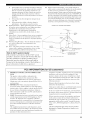
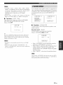
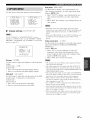
Outdoor Antenna Grounding - If an outside antenna or
cable system is connected to the product, be sure the antenna
or cable system is grounded so as to provide some
protection against voltage surges and built-up static charges.
Article 810 of the National Electrical Code, ANSl/NFPA 70,
provides inlormation with regard to proper grounding of the
mast and supporting structure, grounding of the lead-in wire
to an antenna discharge unit, size o! grounding conductors,
location ol antenna discharge unit, connection to grounding
electrodes, and requirements lor the grounding electrode.
perlbrmance - this indicates a need lbr service.
Replacement Parts - When replacement parts are required,
be sure the service tcchnician has used replacement parts
specified by the manufacturer or have the same
characteristics as the original part. Unauthorized
substitutions may result in fire, eleclric shock, or other
hazards.
20
21
EXAMPLEOFANTENNAGROUNDING
MASV
_--___
Salety Check- Upon completion ol any service or repairs to
this product, ask the serxice technician to perlorm safety
checks to determine that the product is in proper operating _
22
23
_
_
LEAD _N
w,nE
GROUND
_//
CLAMP-
condition.
Wall or Ceiling Mounting - The unit should be mounted
__
-7_-_
mannlacturer,
Heat - lhe product should he situated away from heat
sources such as radiators, heat registers, sto'_es, or other
i
l
...........
s_<v;,_c
c_pwm______
_
]
/
I-;
_
(N
It
products (including ampliliers)that
Note
to CATV system
produce beat.
_
installer:
*_-_?_[;_3
This reminder is provided to call the CATV system
installer's attention to Article 820-40 of the NEC that
provides
guidelines
for proper
particular,
specifies
connected
to the grounding
grounding
that the cable ground
system
........ :M:_:
......
_._cAm_0 _Am./
NEC.A_,O.A_O_,OA_OO0_
and, in
shall be
of the building,
as
close to the point of cable entry as practical.
FCC INFORMATION
1
IMPORTANT
NOTI(E:
DO NOT MODIFY
THIS
Compliance with FCC regulations does not guarantee that
interference will not occur in all installations. If this
UNIT!
This product, when installed as indicated in the
inslructions contained in this manual, meets FCC
rcquii'ements. Modifications
not expressly approved by
Yamaha may void your authority, granted by the FCC, to
use the product.
IMPORTANT:
When connecting this product to
accessories and/or another product use only high quality
shielded cahles. Cable/s supplied witlr tlris product MUST
be used. Follow all installation instructions. Failure to
lollow instructions could void your FCC authorization
use this product in the USA.
(for US customers)
to
NOTE: This product has been tested and lound to comply
with the requirements listed in FCC Regulations, Part 15
lot Class "B" digital devices. Compliance with these
requirements provides a reasonable level of assurance that
your use of this product in a residential environment will
not result in harmfld interference with other electronic
devices.
This equipment generatcs/uses radio Dequencies and, if
not installed and used according to the instructions lound
in the users manual, may cause interference harmful to the
operation of other electronic devices.
product is found to be the soulve of interference, which
can be determined by turning the unit "OFF" and "ON",
please n'y to eliminate the problem by using one of the
lollowing measures:
Relocate either this product or the device that is being
affected by the interlbrence.
Utilize power oudets that are on diflbrent branch (circuit
breaker or fuse) circuits or install AC line filter/s.
In the case of radio or TV interference, relocate/reorient
the antenna. If the antenna lead-in is 300 ohm ribbon lead
change the lead-in to coaxial type cable.
If these corrective measures do not produce satislhctory
results, please contact the local retailer authorized to
distribute this type of product. If you can not locate the
appropriate retailer, please contact Yamaha Electronics
Corp., U.S.A. 6660 Orangetborpe Ave, Buena Park, CA
90620.
The above statements apply" ONLY to those products
distributed by Y:alnaha Corporation of America or its
subsidiaries.
1 Toassure
thefinest
performance,
please
read
thismanual 15
carefully.
Keep
itinasali:
place
forfutm'e
refl:rence.
2 lnstall
thissound
system
inawellventilated,
cool,
dry,
clean
placeaway
fromdirect
sunlight,
heat
sources,
vibration, 16
dust,
moisture,
and/or
cold.
Allowventilation
space
ofatleast
30cmonthetop,20cmontheleftand
right,
and
20clnon 17
theback
ofthisrefit.
3 Locate
thisunitaway
fl-om
other
electrical
appliances,
motors,
ortransformers to avoid hLni]ming SoLmds.
18
4
Do not expose this unit to sudden tcmperaturc changes from
cold to hot, and do not locate this unit in an environment with
high humidity (i.e. a room with a hunfidifier) to prevent
condensation inside this unit, which may cause an electrical
shock, fire, damage to this unit, and/or personal iNury.
5
Avoid installing this unit where foreign objects may 15,11
onto
this unit and/or this unit may be exposed to liquid dripping or
splashing. On the top of this refit, do not place:
Other components, as they may cause damage and/or
discoloration on the sttrlhce of this unit.
Bttrning objects (i.e. candles), as they may cause fire,
damage to this unit, and/or personal injury.
Containers with liquid in them, as they may 15,11
and liquid
may catlse electrical shock to the user and/or damage to
this unit.
6
Do not cover this unit with a newspaper, tablecloth, curtain,
etc. in order not to obstruct heat radiation. If the temperature
inside this unit rises, it may cause fire, danmge to this unit,
and/or personal injury.
7
Do not plug in this unit to a wall oudet until all connections
are complete.
8
Do not operate this unit upside-down. It may overheat,
possibly causing damage.
Do not use force on switches, knobs and/or cords.
9
10 When disconnecting the power cable from the wall outlet,
grasp the plug; do not pull the cable.
11 Do not clean this refit with chemical solvents; this might
damage the finish. Use a clean, dry cloth.
12 Only voltage specified on this unit must be used. Using this
unit with a higher voltage than specified is dangerous and may
cause fire, damage to this unit, and/or personal injury.
YAMAHA will not be held responsible for any damage
resulting from use of this unit with a vohage other than
specified.
13 To prevent damage by lighming, keep the power cord and
outdoor antennas disconnected fl-om a wall outlet or the unit
during a lightning storm.
14 Do not attempt to modify or fix this unit. Contact qualified
YAMAHA service personnel when any service is needed. The
cabinet should never be opened lor any reasons.
When not planning to use this unit liar long periods of time
(i.e. vacation), disconnect the AC power plug from the wall
outlet.
Install this unit near the AC outlet and where the AC power
plug can be reached easily.
Be sure to read the "TROUBLESHOOTING"
section on
common operating errors belore concluding that this unit is
lhuhy.
Belore moving this unit, press MASTER ON/OFF to release it
out,aard to the OFF position to turn off this unit, the main
room, Zone 2 and Zone 3 and then disconnect the AC power
plug from the AC wall outlet.
19 VOLTAGE SELECTOR (Asia and General models only)
The VOUI'AGE SELECTOR on the rear panel of this unit
must be set liar your local main voltage BEFORE plugging
into the AC wall oudet. Vohages are:
Asia model ............................ 220/230-240 V AC, 50160 Hz
General model ........ 110112012201230-240 V AC, 50160 Hz
WARNING
TO REDUCE
THE RISK
OF FIRE OR ELECTRIC
SHOCK, DO NOT EXPOSE
OR MOISTURE.
THIS
As long as this unit is connected
it is not disconnected
to the AC wall outlet,
fi'om the AC power
if you turn off this unit by MASTER
state, this unit is designed
quantity
UNIT TO RAIN
source even
ON/OFF.
to consume
in this
a very small
of power.
FOR CANADIAN
CUSTOMERS
To prevent electric shock,
wide slot and fully insert.
match wide hlade of plug to
This Class B digital apparatus
[CES-003.
complies
with Canadian
POUR LES CONSOMMATEURS CANADIENS
Pour (viter les chocs (lectriques, introduire la lame la
plus large de la fiche dans la borne correspondante de
la prise et pousser jusqu'au fond.
Cet appareil numdrique de la classe Best conforme a
la norme NMB-003 du Canada.
IMPORTANT
Please record the serial number of this unit in the space
below.
MODEL:
Serial No.:
The serial number is located on the rear of the unit.
Retain this Owner's Manual in a safe place for future
reference.
,==
III
FEATURES .............................................................
GETTING
STARTED ............................................
2
3
Supplied accessories ..................................................
CONTROLS
AND FUNCTIONS
.........................
3
4
Front panel .................................................................
Remote control ...........................................................
Zone 2/Zone 3 remote control ...................................
Preparing the remote control .....................................
Front panel display ..................................................
Rear panel ................................................................
4
6
8
9
10
12
CONNECTIONS
..................................................
Placing speakers .......................................................
Connecting speakers ................................................
Using bi-amplification connections .........................
Information on jacks and cable plugs ......................
Information on HDMI ..............................................
Audio and vide() signal flow ....................................
Connecting a TV monitor or projector ....................
Connecting other components .................................
Connecting a multi-format player
or an external decoder. ........................................
13
13
14
17
18
19
20
21
22
26
Connecting a YAMAHA iPod universal dock ........ 27
Using the VIDEO AUX jacks on the fl'ont panel .... 27
Connecting the FM and AM antennas ..................... 28
Connecting the power cahle .....................................
29
Setting the spe&er impedance ................................. 30
Turning on and off the power. ................................. 31
AUTO SETUP .......................................................
32
Using AUTO SETUP ..............................................
PLAYBACK
..........................................................
32
38
Basic procedure .......................................................
Selecting audio input jacks (AUDIO SELECT) ......
Selecting the MULTI CH INPUT component .........
Using your headphones ............................................
Muting the audio output ...........................................
Displaying the input source information .................
Playing video sources
in the background of an audio source ..................
Using the sleep timer ...............................................
SOUND FIELD PROGRAMS .............................
38
40
41
41
41
42
Selecting sound field programs ...............................
Sound field program descriptions ............................
Enjoying unprocessed input sources ........................
USING AUDIO FEATURES
...............................
44
45
49
50
Enjoying pure hi-fi sound ........................................
Adjusting the tonal quality .......................................
Adjusting the speaker level ......................................
Enjoying multi-channel sources
in 2-channel stereo ...............................................
Selecting the Compressed Music
Enhancer mode ....................................................
Selecting the night listening mode ...........................
50
50
51
FM/AM TUNING ..................................................
FM/AM controls and functions ...............................
Automatic tuning .....................................................
Manual tuning ..........................................................
Automatic preset tuning ...........................................
Manual preset tuning ...............................................
Selecting preset stations ...........................................
Exchanging preset stations ......................................
XM SATELLITE
RADIO TUNING ...................
54
54
55
56
57
58
59
60
61
Connecting the XM Passport System ...................... 61
XM Satellite Radio controls and functions .............. 62
Activating XM Satellitc Radio ................................
Basic XM Satellite Radio operations .......................
Setting the XM Satellite Radio preset channels ......
Displaying the XM Satellite P.adio inli_rmation ......
USING iPod ...........................................................
63
65
70
71
73
Conn'(filing iPod ......................................................
RECORDING ........................................................
73
75
m
rr
ADVANCED
SOUND
CONFIGURATIONS
.....76
Changing sound field parameter settings ................. 76
Selecting decoders ...................................................
80
CUSTOMIZING
THIS UNIT
(MANUAL SETUP) ..........................................
Using SET MENU ...................................................
1 BASIC MENU ......................................................
2 SOUND MENU ....................................................
3 INPUT MENU ......................................................
4 OPTION MENU ...................................................
REMOTE
CONTROL
FEATURES
.................
84
86
87
91
94
97
101
Controlling this unit, a TV,
or other components ..........................................
101
Setting remote control codes .................................
103
Programming codes from other remote controls ... 105
Changing source names in the display window..... 106
Macro programming features ................................ 107
Clearing configurations .........................................
110
USING MULTI-ZONE
CONFIGURATION
... 113
Connecting the Zone 2 and Zone 3 components ... 113
Controlling Zone 2 or Zone 3 ................................
114
ADVANCED
SETUP ..........................................
117
Using ADVANCED SETUP .................................
Setting remote control ID ......................................
117
119
TROUBLESHOOTING
.....................................
RESETTING
THE SYSTEM .............................
GLOSSARY .........................................................
SOUND FIELD PROGRAM
INFORMATION
.............................................
122
130
131
43
43
44
PARAMETRIC
EQUALIZER
INFORMATION
.............................................
SPECIFICATIONS
.............................................
134
135
136
51
52
53
APPENDIX
(at the end of this manual)
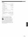
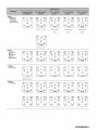
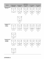
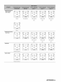
• SOUND OUTPUT IN EACll SOUND FIELD
PROGRAM
• LIST OF REMOTE
CONTROL
CODES
1En
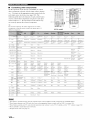
Built-in
•
7-channel
power
amplifier
iPod controlling
•
Minimnm RMS output power
(20 Hz to 20 kHz, 0.1)4% THD, 8 f2)
Front: 130 W + 13(1W
Center: 130 W
Surround: 130 W + 130 W
Surround back: 130 W + 13(1W
Sound
capability
DOI"K terminal to connect a YAMAHA iPod universal dock
(such as the YDS-10, sold separately), which supports iPod
(Click and Wheel), iPod nano, and iPod mini
Other
field programs
features
•
YPAO (YAMAHA Parametric Room Acoustic Optimizer) li)l"
•
antomatic speaker setup
192-kHz/24-bit D/A converter
•
Proprietary YAMAHA teclmology lor the creation of sound
fields
•
OSD (on-screen display) menus that allow you to optimize
this mlit to suit your individual audiovisual system
•
•
Dolby Digital/Dolby Digital EX decoder
DTS/DTS-ES Matrix 6.1, Discrete 6.1, DTS Neo:6,
DTS 96/24 decoder
•
•
Dolby Pro Logic/Dolby
decoder
6 or 8-channel additi(mal input jacks for discrete multichannel input
Analog video interlace/proglvssive
conversion from 480i
(NTSC)/576i (PAL) to 480p/576p
S-video signal input/output capability
Component video input!output capability includes (3
COMPONENT VIDEO INs and 1MONITOR OUT)
• Neural Surround decoder (U.S.A. and Canada models only)
• Virtual CINEMA DSP
•SlLENT
ClNEMA
Sophisticated
•
•
•
random and direct preset tuning
Atltomatic
preset tuning
Preset station shifting capability (preset editing)
(U.S.A.
•
tuner
40-station
XM Satellite
•
AM/FM
Radio
and Canada
•
Pro Logic ll/Dolby Pro Logic llx
models
only)
XM Satellite Radio tuning capability (using tl_e"XM Passport
System" sold separately)
Neural Surround decoder to play back the surround sound
content of XM Satellite Radio broadcasts in multi-channels,
•
•
•
•
•
•
Optical and coaxial digital audio signal jacks
Pure Direct mode for pure hi-fi sound lot all sources
Cinema and mnsic night listening modes
Compressed Music Enhancer mode to improve the sound
•
quality of compression artifilcts (such as the MP3 format) to
that of a high-quality stereo
Remote control with preset remote control codes, learning and
•
•
macro capability
ZONE 2/ZONE 3 custom installation fi,cility
Zone switching capability between the main zone and
ZONE 2/ZONE 3 using ZONE CONTROLS
•
Sleep timer
resulting in a full surround sound experience
HDMI
•
(High-Definition
Multimedia
Interface)
HDMI interface for standard, enhanced or
high-definition video (includes 1080p video signal
u:ansmission) as well as multi-channel digital audio based on
HDMl version 1.2a
•
Analog video to HDMl digital video up-conversion
(compositc video +_ S-video _> component video > HDMI
digital vide()) capability lor monitor out
rlO_
DIGITAL,
EX
Manufactured under license from Dolby Laboratories.
"Dolby", "Pro Logic", and the double-D symbol are trademarks
of Dolby Laboratories.
Manufactured under license from Digital Theater Systems, lnc.
"DTS", "DTS-ES", "NEO:6", and "DTS 96/24" are trademarks
of Digital Theater Systems, lnc. Copyright 1996, 2003 Digital
Theater Systems, lnc. All right reserved.
iPod®
"iPod" is a trademark of Apple ('omputer, Inc., registered in the
U.S. and other countries.
"HDMI", the "HDMI" logo and "High-Definition Multimedia
lnterlY_ce"arc trademarks or registered trademarks of HDMI
Licensing LLC.
SILENT
CINEMA
TM
"SILENT CINEMA" is a trademark of YAMAHA
CORPORATION.
The XM name and related logos are registered trademarks of XM
Satellite Radio lnc.
_neura[
So
qfaOOSO
Surround Ix1name and related logos are trademarks owned
by Neural Audio Corporation.
Neqral
2 En
Check
that you received
all of the following
parts.
Remote control
Zone 2/Zone 3
remote control
(except Europe model)
0000
U_©'U
Batteries (6)
(AAA, R03, UM-4)
0000
©O'U'©
•_
_o
_o _
OOO_
@@@@
@
D
@@@0
0@_0
®®0®
{#YAMAIA
Speaker
terminal
wrench
Power cable
Optimizer
microphone
_
Indoor FM antenna
(U.S.A., Canada, China, Asia, General,
and Korea models)
Indoor FM antenna
(Europe, U.K. and Australia models)
AM loop antenna
About this manual
• -"4£indicates a tip for your operation.
• Some operations can be perlormed by using either the butons on the fl'ont panel or the ones on the remote control. In case the
button names dil'lier between the front panel and the remote control, the button name on the remote control is given in
parentheses.
• This manual is printed prior to production. Design and specifications are subject to change in part as a result of improvements,
etc. In case of differences between the manual and product, the product has priority.
3 En
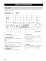
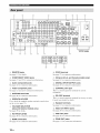
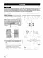
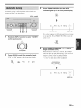
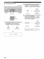
This section describes only the amplifier controls and functions of this unit. See the following pages for details about
other control and functions.
• AM/FM tuning ........................... see page 54
• XM satellite radio tuning ........... see page 62
_YAMAH
z
uA_ zoN_
©
L
I
(U.S.A.
@ MASTER ON/OFF
Turns this unit on or off(see page 31).
@ MAIN ZONE ON/OFF
Turns on the main zone or sets it to the standby mode
(see page 31).
• In the standby mode, this unit consumes a small amount of
power in order to receive inli-ared signals li-om the remote
controh
• When you turn on this unit, there will be a 4 to 5-second delay
belore this refit can reproduce sound.
• This button is operational only when MASTER ON/OFF is
pressed inward to the ON position.
@
INPUT
Selects
4 En
selector
the desired
input source (see page 38).
model)
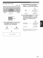
@ AUDIO SELECT
'Ibggles the priority for the type of audio input,jack
between "AUTO", "HDMI", "COAX/OPT" and
"ANALOG" when one component is connected to two or
more input ,jacks (see page 40).
@ TONE CONTROL
Adjusts the bass/treble balance of the front left, front right
and center channels in conjunction with the PROGRAM
selector (see page 50).
@ STRAIGHT
Turns the sound field programs off or on. When the
"STRAIGHT" mode is selected, 2-channel or multichannel input signals are output directly fi'om their
respective speakers without effect processing (see
page 49).
@
MULTI
ZONE
buttons
ZONE
2 ON/OFF
Turns on Zone 2 only or sets it to the standby
mode.
See page 114 for details.
ZONE
3 ON/OFF
Turns on Zone 3 only or sets it to the standby
mode.
See page 114 for details.
@ PROGRAM selector
• Selects sound field programs (see page 44).
• Adjusts the bass/treble balance in conjunction with
TONE CONTROL (see page 50).
@ OPTIMIZER MIC jack
Use to connect and input audio signals from the supplied
optimizer microphone in the "AUTO SETUP" procedure
(see page 32).
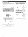
@
Outputs
ZONE
@
CONTROLS
Switches
the zone you want to control
between
the
main zone, Zone 2 and Zone 3. See page 114 for
details.
-#Alter you
@
listening
with
VIDEO
Input audio
AUX jacks
and video signals
from a portable
such as a game console
or
a video
external
camera
(see page 27).
Front
The audio signals input at the DOCK terminal on the rear panel
take priority over the ones input at tile VIDE() AUX jacks.
panel
display
about the operational
status of this unit
@
ENHANCER
Music
Enhancer
Remote
level of all audio channels.
This does not affect the AUDIO OUT (REC) level.
control
signals
sensor
•
from the remote
control
(see page 9).
Turns on or off the night listening
modes
(see page 53).
Opening and closing the front panel
door
When you want to use the controls behind the fi'ont panel
NIGHT
PURE
the output
mode
(see page 52).
Receives
VOLUME
Controls
Turns on or off the Compressed
@
for private
(see page 41).
To reproduce the source signals input at these jacks, select
"V-AUX" as the input source.
(see page 10).
@
headphones
source
jack
audio signals
press ZONE CONTROLS, the indicator for the
currently selected zone flashes in the front panel display for
approximately 5 seconds. While the indicator is flashing,
perform the desired operation.
Shows information
@
4% PHONES
These buttons are operational only when MASTEP, ON/OFF
is pressed inward to the ON position.
the panel.
controls.
DIRECT
Turns on or off the Pure Direct
door, open the door by gently
pressing
Keep the door closed
on the lower part of
when not using these
mode (see page 50).
To open, press
gently
on the lower
part of the panel.
SEn
I_ohVIl_o_Ui.'f-,l;l_l_#/;[_i[ol;l.:.
•
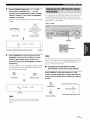
Remote
control
controls
and functions
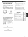
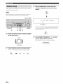
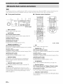
This section describes only the amplifier controls and functions of this unit. See the following pages for details about
other control and fimctions.
•
•
•
•
•
AM/FM tuning ........................................
see page 54
XM satellite radio tuning ........................ see page 62
Controlling a TV ................................... see page 101
Controlling other components ............... see page 102
Controlling option components ............. see page 103
The operation mode of the remote control buttons in the shaded
area below depends on the operation mode selector position. Set
the operation mode selector to AMP to control this unit.
©
_16)
@
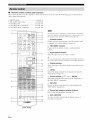
@ Infrared window
Outputs infrared control signals. Aim this window at the
component you want to operate (see page 9).
@ TRANSMIT indicator
Hashes while the remote control is sending infi'ared
signals.
0
@ Input selector buttons
Select the input source you want to control.
-#Theselected input source name appem'sin the display window on
the remote control showing which source is currently operationah
--@,',
@ Display window
Shows the name of the selected input source that you can
control.
@ LEVEL
Selects the speaker channel to be adjusted and sets the
output level (see page 51).
@ Cursor buttons A / V / <1 / _>, ENTER
Select and adjust the sound field program parameters or
the "SET MENU" parameters.
@ RETURN
Returns to the previous menu level when adjusting the
"SET MENU" parameters.
@ Sound field program selector buttons
Select sound field programs (see page 44).
@ SUR. DECODE
Activates decoders to play back 2-channel sources in
surround (see page 80).
J
(U.S.A.
6 En
model)
@ MACRO ON/OFF
Turns on or off the macro function (see page 107).
@ VOLUME +IIncreases or decreases the volmne level.
@ MACRO
MUTE
Progran_s a series of operations to he controlled with a
single button (see page 107).
Mutes the audio output. Press again to restore the audio
output to the previous volume level (see page 41).
@ STANDBY
@ PURE DIRECT
Sets the main zone to the standby mode (see page 31).
Tm'ns on or off the pm'e direct mode (see page 50).
Note
@ SET MENU
Enters "SET MENU" (see page 86).
This button is operational only when MASTER ON/OFF on the
front panel is pressed inward to the ON position.
@ POWER
Turns on the main zone (see page 31).
_ PARAMETER
Displays sound field parameter settings in the on-screen
display (OSD) (see page 76).
@ STRAIGHT
Note
This button is operational only when MASTER ON/OFF on the
front panel is pressed inward to the ON position.
@ AUDIO SEL
'Ibggles the priority for the type of audio input jack
between "AUTO", "HDMI', "COAX/OPT" and
"ANALOG" when one component is connected to two or
more input .jacks (see page 40).
SLEEP
Sets the sleep timer (see page 43).
@ MULTI CH IN
Selects the component connected to the MUKI't CH
INPUT jacks as the input source when using an external
decoder, etc. (see page 41).
SELECT A / V
Selects another input source that you can control
independently of the input source selected with the input
selector buttons.
@ Operation mode selector
Selects the operation mode of the remote control buttons
in the shaded area.
AMP
Operates the amplifier function of this unit.
SOURCE
Operates the component selected with an input
selector button (see page 102).
Tm'ns the sound field programs off or on. When the
"STRAIGHT" mode is selected, 2-channel or multichannel input signals are output directly from their
respective speakers without effect processing (see
page 49).
_
EXTD SUN.
Switches hetween 5.1 and 6.1/7.l-channel
multi-channel sources (see page 80).
playback of
@ SELECT
Selects decoders for 2-channel som'ces (see pages 80 and
82).
@ ENHANCER
Turns on or off the Compressed Music Enhancer mode
(see page 52).
NIGHT
Tm'ns on or off the night listening modes (see page 53).
RENAME
Changes the name of the input source in the display
window (see page 106).
@ CLEAR
Clears remote control fimctions acquired from the learn,
macro and/or rename features (see page 110).
LEARN
Programs remote control codes of functions from other
remote controls (see page 105).
TV
Operates the TV assigned to either DTV/CBL or
PHONO (see page 101).
• To set the remote control codes lor other components, see
page 103.
• When you set the remote control codes lor both DTV/CBL and
PHONO (see page 103),priority is given to the one set for
DTV/CBL.
TEn
E_ohtIl_o]Ui.'f-_f;l_I_#/;[_ifol;l.:.
This section
describes
the function
of each control
Zone 2/Zone 3 remote control used to control
functions of Zone 2 or Zone 3.
See the following
and functions.
pages
• AM/FM
........................................
tuning
• XM Satellite
for details
Radio tuning
on the
the amplifier
about other controls
......................
see page 54
see page 62
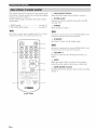
Zone 2/Zone 3 remote control is supplied with U.S.A., Canada,
Australia, U.K., China, Asia and General models only.
@ Input selector buttons
Select the desired input source of Zone 2 or Zone 3.
@ IDI/ID2 switch
Switches the remote control ID between IDI and ID2
(see page 104).
@ POWER
Turns on Zone 2 or Zone 3.
This button is operational only when MASTER ON/OFF on fire
ITontpanel is pressed inward to tile ON position.
@ STANDBY
Sets Zone 2 or Zone 3 to the standby mode.
..............................
@
This button is operational only when MASTER ON/OFF on fire
ITontpanel is pressed inward to fire ON position.
@--
@ VOLUME +IIncreases or decreases the volume level of Zone 2 or
Zone 3.
@ MUTE
Mutes the sound of Zone 2 or Zone 3. Press again to
restore the audio output to the previous volume level.
VOLUME
_(6)
@--
ZO,E_
ZO,Ea
(U.S.A. model)
SEn
@ ZONE 2/ZONE 3 switch
Switches between the operation mode of Zone 2 and that
of Zone 3.
_ol;ll:_oll_'-lK4;l_lI._#l;[_ifo]|v_,
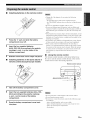
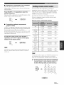
Installing batteries in the remote control
• Change all of the batteries if you notice the following
conditions:
_-_
_-_
- the operation range of the remote control decreases.
the TRANSMlT
dim.
indicator does not flash or its light becomes
• Do not use old batteries together with new ones.
• Do not use different types of batteries (such as alkaline and
manganese batteries) together. Read the packaging carefully as
these dill'crcnt types of batteries may have the same shape and
color.
Press the v
compartment
part and slide the battery
cover off.
• If the batteries have leaked, dispose of them immediately. Avoid
touching the leaked material or letting it come into contact with
clothing, etc. Clean the battery compamnent thoroughly before
installing new batteries.
• Do not throw away batteries with general house waste: dispose
of them correctly in accordance with your local regulations.
• If the remote control is without batteries lot more than 2
minutes, or if exhausted batteries remain in the remote control,
the contents of the memory may be cleared. When the memory
is cleared, insert new batteries, set up the remote control code
and program any acquired functions that may have been
cleared.
Insert the four supplied batteries
(AAA, R03, UM-4) according to the polarity
markings (+ and -) on the inside of the
battery compartment.
3
•
Slide the cover back until it snaps into place.
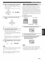
Installing batteries in the Zone 2/Zone 3
remote control (Except Europe model)
•
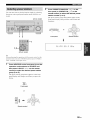
Using the remote control
The remote
control
transmits
Be sure to aim the remote
control
sensor
a directional
control
directly
infrared
ray.
at the remote
on this unit during operation.
Remote control sensor
Approximately 6 m (20 ft)
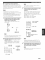
1
2
Take off the battery compartment
cover.
Insert the two supplied batteries (AAA, R03,
UM-4) according to the polarity markings
(+ and -) on the inside of the battery
compartment.
Snap the battery compartment
into place.
cover back
• Do not spill water or other liquids on the remote control.
• Do not drop the remote control.
• Do not leave or slore the remote control in the lollowing types
of conditions:
places of high humidity, such as near a bath
- places of high temperaulres, such as near a heater or stove
- places of extremely low temperatures
dusty places
9En
The XM indicator is only applicable to the U.S.A. and Canada models and the cursor on the left of the XM indicator lights tip only when
"XM" is selected as tile input source. For details, see "Basic XM Satellite Radio operations" on page 65.
DOCK®DVNVCFt2 _VCFll _,CBL/SAT CDTV _'DVD _MD/TAPE _CD-R _'CD _'PHON0 MULTIC
_T&_°F_2_
C_D_]DIGITALYPAO
ENHANCER
.
0 ::::1
m:::m:::::1
:::::
:m:::::1
:::::
:1:::
m:=:m:::::1
1::::
.....
CINEMA_SILENT
_
96
_
_
_
_
_
_
_
_
_
_
_
_
_
_
_
_oTU_,STERE0°
96/2_
_ _"-"-"-"( (-"(-"-"
-"(-"(-"
-"-"-"-"(
-"-"-"-"-"
-"(-"(-"
-"-"-"-"(
-"-"-"-"-"
-"(-"-"-"
(-"(-"(-"(-"(-"
-"-"-"-"(
(-"-"-"-"
-"(-"(-"
S_{_
PTY_RT_
_TE_
ZONE3ZONE2
_
SLEEP EON_
=, = =, ,.. = =, ,.,,= ,.. ,,,,==,
P;Y,O p,
] F
...................................................................................................
X
!
@ HDMI indicator
Lights up when the signal of the selected input source is
input at HDMI tN 1 or HDMI IN 2jacks (see page 19).
@ DOCK indicator
Lights up when you station your iPod in a YAMAHA iPod
universal dock (such as the YDS-I(), sold separately)
connected to the DOCK terminal of this unit
(see page 27).
@ Battery charge indicator
Lights up when this unit charges the battery of the
stationed iPod in the standby mode of this unit. (see
page 73).
@ Input source indicators
The corresponding cursor lights up to show the currently
selected input source.
@ VOLUME level indicator
Indicates the current volume level.
@ MUTE indicator
Flashes while the MUTE function is on (see page 41 ).
@ Multi-information display
Shows the name of the current sound field program and
other information when adjusting or changing settings.
10 En
@ ........
U.S.A.
and Canada
@ ........
U.K. and Europe
models
models
only
only
@ 96/24 indicator
Lights up when a DTS 96/24 signal is input to this unit.
@ Input channel and speaker indicators
[_
_
[_
_:a--
Presence
[_T
lnpm channel
_._S[_=
Surround
speaker
indicators
indicators
back speaker
indicators
Input channel indicators
indicate the channel components of the current digital
input signal.
Presence and surround back speaker
indicators
Light up according to the number of presence and
surround back speakers set R>r"PRESENCE SP" (see
page 89) and "SB L/R SP" (see page 89) in "SOUND
MENU" when "TEST" in "SOUND MENU" is set to
"ON" (see page 92).
_.,#._
YO[I can
lnake
settings lot the
presence
and
s[lrround
back
speakers amomatically by running "AUTO SETUP" (see
page 32) or manually by adjusting settings lor "PRESENCE SP"
(see page 89) and _'SBL/R SP" (see page 89) in "SOUND
MENU".
@ neural indicator
(U.S.A. and Canada models only)
Lights up when the Nem'al Surround decoder is activated
(see page 81 ).
@ DSP indicators
The respective indicutor lights up when any of the DSP
sound field programs are selected.
CINEMA DSP indicator
Lights up when you select a CINEMA DSP sound
field program (see page 45).
HiFi DSP indicator
Lights up when you select a HiFi DSP sound field
program (see page 45).
@ VIRTUAL indicator
Lights up when Virtual CINEMA DSP is active (see
page 49).
@ YPAO indicator
Lights up when you run "AUTO SETUP" and when the
speaker settings set in "AUTO SETUP" are used without
any modifications (see page 32).
@ DSD indicator
Lights up when this trait is producing DSD (Direct Stream
Digital) digital audio signals.
@ ENHANCER indicator
Lights up when the Compressed Music Enhancer mode is
turned on (see page 52).
@ PCM indicator
Lights up when this trait is reproducing PCM (Pulse Code
Modulation) digital audio signals.
@ Dolby decoder indicators
The respective indicator lights up when any of the Dolby
decoders of this unit funcfion.
@ Sound field indicators
Light up to indicate the active DSP sound fields.
PresenceDSP sound field
_11_/-- Listeningposition
I)SP sound Hctd
Surround
"7_
DSP sound llcld
back DSP sound field
Headphones indicator
Lights up when headphones are connected (see page 41 ).
SILENT CINEMA indicator
Lights up when headphonesare connected and a sound
fiekl program is selected (see page 49).
DTS decoder indicators
The respective indicator lights up when any of the DTS
decoders of this unit fimction.
@ Tuner indicators
Lights up when this trait is in the FM, AM or XM Satellite
Radio tuning mode.
TUNED indicator
Lights up when this unit is timed into a station
(see page 54).
STEREO indicator
Lights up when this unit is receMng a strong signal
for an FM stereo broadcast while the AUTO indicator
is lit (see page 54).
AUTO indicator
Lights up when this unit is in the automatic tuning
mode (see page 54).
MEMORY indicator
Hashes to show that a station can be stored
(see page 57).
_ ZONE2/ZONE3 indicators
Lights up when Zone 2 or Zone 3 is turned on
(see page 114).
_ NIGHT indicator
Lights up when you select a night listening mode
(see page 53).
@ SLEEP indicator
Lights up while the sleep timer is on (see page 43).
@ Radio Data System indicators
(U.K. and Europe models only)
PS, PTY, RT and CT
Light up according to the selected P.adio Data System
display mode.
EON
Lights up when the EON data service is being
received.
PTY HOLD
Lights up while searching for the P.adio Data System
stations in the PTY SEEK mode.
11 E,
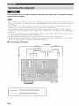
E_ehVllE:_e_lF-*!_Velal#hV[_ifehVl4
Aci_
Ir _
roll
IL
roll
ACOUTL_S
F_3F_-S
L_J
L
U.S.A.
I
model)
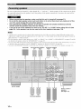
@ REMOTE jacks
See page 113 for details.
@ DOCK terminal
See page 27 for connection information.
@ COMPONENT VIDEO jacks
See pages 21 and 22 for connection information.
@ XM jack (U.S.A. and Canada models only)
See page 61 for connection information.
@ Audio component jacks
See page 24 for connection information.
@ DIGITAL INPUT/OUTPUT jacks
See page 22 for connection information.
@ Video component jacks
See pages 21 and 22 for connection information.
@ CONTROL OUT jack
This is a control expansion terminal for custom
installation.
@ ANTENNA terminals
See page 28 for connection information.
@ WRENCH HOLDER
Use to hook the supplied speaker terminal wrench when
not in use (see page 15).
@ VOLTAGE SELECTOR
(Asia and General models only)
See page 29 for details.
@ RS-232C terminal
This is a control expansion terminal for factory use only.
Consult your dealer for details.
@ Speaker terminals
See page 14 for connection information.
@ MULTI CH INPUT jacks
See page 26 for connection information.
@ AC IN/OUTLET(S)
See page 29 for connection information.
@ PRE OUT jacks
See page 25 for connection information.
@ HDMI connectors
See page 19 for connection information.
@ ZONE OUT jacks
See page 113 for connection information.
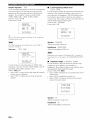
12 En
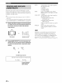
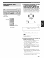
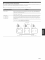
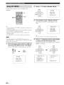
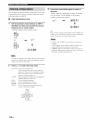
The speaker layout below shows the speaker setting we
recommend. YOUcan use it to enjoy CINEMA DSP and
multi-channel audio sources.
qD
Front left and right speakers (FL and FR)
The front speakers are used for the main source sound plus
effiect sounds. Place these speakers at an equal distance from
the ideal listening position. The distance of each speaker
from each side of the video monitor should be the same.
Center speaker (C)
The center speaker is for the center channel sounds
(dialog, vocals, etc.). If for some reason it is not practical
to use a center speaker, you can do without it. Best results,
however, are obtained with the full system. Place the
center speaker centrally between the front speakers and as
close to the monitor as possible, such as directly over or
under it.
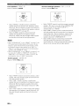
Surround left and right speakers (SL and SR)
The surround speakers are used for effect and surround
sounds. Place these speakers behind your listening
position, facing slightly inwards, about 1.8 m (6 It) above
the floor.
/
30 cm (12 in) or more
Surround back left and right speakers
(SBL and SBR)
The surround back speakers supplement the surround
speakers and provide more realistic front-to-b_tck
transitions. Place these speakers directly behind the
listening position and at the same height as the surround
speakers. They should be positioned at least 30 cm (12 in)
apart, ideally, they should be positioned at the same width
as that of the front speakers.
FL
1.8 m (6 It)
0.5tolm(lto3ft)
0,5to
_................._
1.8 m (6 It)
1 m (1 to 3 ft)
Presence left and right speakers (PC and PR)
The presence speakers supplement the sound fi'om the front
speakers with extra ambient effects produced by CINEMA
DSP (see page 134). These effects include sounds that
fihnmakers intend to locate a little f_rther hack behind the
screen in order to create more theater-like ambience. Place
these speakers at the front of the room about 0.5 to 1 m (1
to 3 it) outside the front speakers, fhcing slightly inward,
and about 1.8 m (6 it) above the floor.
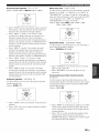
Subwoofer (SW)
The use ofu subwoofer with u built-in amplifier, such as
the YAMAHA Active Servo Processing Subwoofer
System, is effective not only for reinR)rcing bass
frequencies from any or all channels, but also for high
fidelity sound reproduction of the LFE (low-frequency
effect) channel included in Dolby Digital and DTS
sources. The position of the subwoofer is not so critical,
because low bass sounds are not highly directional. But it
is better to place the subwoofer near the front speakers.
Turn it slightly toward the center of the room to reduce
wall reflections.
13 En
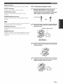
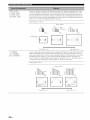
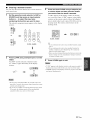
Be sure to connect the lea channel (L), right channel (R), "+" (red) and "" (black) properly. If the connections are faulty,
no sound will be heard from the speakers, and if the polarity of the speaker connections is incorrect, the sound will be
unnatural and lack bass.
•
•
•
•
Before connecting the speakers, make sure that this unit is turned off (see page 31)
Do not let the bare speaker wires touch each other or do not let them touch any metal part of this
unit This could damage this unit and/or speakers
Use magnetically shielded speakers If this type of speaker still creates interference with the
monitor, place the speakers away from the monitor
If you are to use 6 ohm speakers, be sure to set "SP IMP" to "6_MIN" before using this unit (see
page 30) 4 ohm speakers can be also used as the front speakers (see page 118)
• A speaker cord is actually a pair of insulated cables running side by side. Cables are colored or shaped differently, perhaps with a
stripe, groove or ridge. Connect the striped (grooved, etc.) cable to the "+" (red) terminals of this unit and your speaker. Connect the
plain cable to the "-" (black) terminals.
• The low-frequency signals of other speakers set to "SML"/or "SMALL") or to "NONE" in "SPEAKER SET" (see pages 87 and 89)
are directed to the speakers selected in "LFE/BASS OUT" (see page 87).
• You can connect both surround back and presence speakers to this unit, however they do not output sound simultaneously. You can set
to prioritize either set of speakers using the "PRIORITY" parameter in "MANUAL SETUP" (see page 89).
• You can use the PRESENCE terminals to connect the Zone 2 or Zone 3 speakers as well as the presence speakers (see page 113).
Subwoofer
Surround back speakers
Left
Right
Presence speakers
Right
Left
Center speaker
_!i%!!!i%
(USA
model)
Zone 2 or Zone 3
speakers
(see page 113)
Right
Left
Surround speakers
Right
Left
Front speakers
14 En
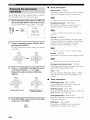
_Oh_h_l_liiOh_
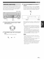
FRONT terminals
Connect front left and right speakers to these terminals.
•
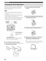
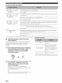
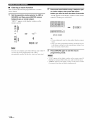
Connecting the speaker cable
CENTER terminals
Remove approximately 10 mm (0.4 in) of
insulation from the end of each speaker
cable and then twist the exposed wires of the
cable together to prevent short circuits.
Connect a center speaker to these terminals.
SURROUND terminals
Connect surround left and right speakers to these
terminals.
SURROUND
BACK terminals
Connect surround back left and right speakers to these
terminals.
10 mm (0.4 in) i
When you use a surround back speaker, connect the speaker tothe
left SURROUND BACKterminal (SINGLE).
2
PRESENCE terminals
Loosen the knob using the supplied speaker
terminal wrench.
Connect presence left and right speakers to these
terminals.
Speaker
terminal
wrench
SUBWOOFER jack
Connect a subwoofer with a huilt-in amplifier (such as the
YAMAHA Active Servo Processing Suhwoofer System)
to this ,jack.
Red: positive (+)
Black: negative (-)
3
Insert one bare wire into the hole on the side
of each terminal.
J
4
Tighten the knob to secure the wire using the
supplied speaker terminal wrench.
15 En
I[_ohw/_ifoJiv
_
•
5
Hook the speaker terminal wrench onto the
WRENCH HOLDER on the rear panel of this
unit when not in use.
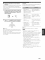
Connecting the banana plug
(except U.K., Europe, Asia and Korea
models)
The banana plug is a single-pole electrical connector
widely used to terminate speaker cables.
Bananaplug
1
•
Connecting
terminals
to the SP2 speaker
Connect Zone 2 or Zone 3 speakers to these terminals (see
page 113).
1
Tighten the knob using the supplied speaker
terminal wrench.
Speakerterminalwrench
Open the tab.
Red: positive (+)
Black: negative (-)
Red: positive (+)
Black: negative (-)
2
2
Insert one bare wire into the hole on the
Insert the banana plug connector into the
end of the corresponding
terminal.
terminal.
Close the tab to secure the wire.
16 En
Youcan also use the banana plug with the SP2 speakerterminals.
Open the tab and then insert one banana plug into the hole on the
tcrminah Do not close the tab after connecting the banana plug.
Some of the speakers
allow
have speaker
bi-amplification
speaker
system.
to enhance
connection
your speakers
support
connecting
shorting
to one speaker
bi-amplification.
system.
if
•
Bi-amplification
connection
To make the bi-amplification
connections,
use the t_RONT
and SURROUND
BACK terminals as shown beh)w. To
activate
the bi-amplification
to "ON"
in "ADVANCED
connections,
SETUP"
set "BI-AMP"
(see page
119).
bars or bridges,
the two red input terminals
the two black input terminals.
bars or bridges
Check
As these speakers
to you, you will note shorting
one connecting
that
of the
This unit alh)ws you to make bi-
amplification
m'e shipped
wire connections
the performance
and the other
Remove
these
This unit
]
only if you plan to bi-amplify
your speakers.
•
Conventional connection
If you want to connect
loudspeakers
connect
your speakers
using the conventional
your speakers
as traditional
connection
using the regular
speaker wire connections
terminal s.
and ignore
method,
left and right
the second
set of
Right
Left
Front speakers
Remove the shorting bars or bridges to separate the LPF (low
pass filter) and HPP"(high pass filter) crossovers.
Right
Left
Front speakers
Shorting bars
or bridges
Shorting bars
or bridges
17En
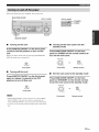
Audio jacks and cable plugs
AUDIO
DIGITAL
0
@
(Red)
Left and right
analog audio
cable plugs
•
COMPONENT
DIGITAL
VIDEO
OPTICAL
COAXIAL
t
Coaxial
digitalaudio
cable plug
Audio jacks
on the availability
of audio jacks
on your other
components.
AUDIO
jacks
For conventional
analog
audio
and right analog
audio cables.
signals
transmitted
Connect
via left
red plugs to the
right jacks and white plugs to the left ,jacks.
DIGITAL
COAXIAL
For digital audio
audio cables.
transmitted
via coaxial
PR
(Blue)
ttt
t
Composite
video cable
plug
S-video
cable plug
(Red)
Component
video cable
plugs
•
Video jacks
This unit has three types of video jacks. Connection
depends Gn tbe availability Gf input,jacks on your video
monitor.
VIDEO jacks
For conventional composite video signals transmitted via
composite video cables.
S VIDEO jacks
jacks
signals
VIDEO
I_
(Green)
t
t
Optical
digital
audio cable
plug
Y
@ ©©©
(Yellow)
(Orange)
This unit has three types of audio jacks. Connection
depends
S VIDEO
o
©©©
t t t
(White)
Video jacks and cable plugs
digital
DIGITAL OPTICAL jacks
For digital audio signals transmitted via optical digital
audio cables.
For S-video signals, separated into the luminance (Y) and
chrominance (C) video signals transmitted on separate
wires of S-video cables.
COMPONENT
For component
luminance
transmitted
VIDEO
video
jacks
signals,
(Y) and chrominance
on separate
separated
into the
(PB, PR) video
wires of component
signals
video cables.
"4¢-You can use the digital jacks to input PCM, Dolby Digital and
DTS bitstreams. When you connect components to both the
COAXIAL and OPTICAL jacks, priority is given to the signals
inpm at the COAXIAL jack. All digital input jacks are
compatible with 96-kHz sampling digital signals.
18 En
This ttnit equips the video connection function. See pages 20 and
97 for details.
This unit has the HDMI IN 1, HDMI tN 2 and HDMI OUT,jacks %r digital audio and video signal input/output. Connect
the HDMI tN 1 or HDMI IN 2,iack of this unit to the HDMI output,jack of other HDMI components (such as a DVD
player). Connect the HDMI OUT,jack of this unit to the HDMI IN ,jack of other HDMI components (such as a TV and a
projector).
The video or audio signals input at the HDMI IN 1 or HDMI IN 2,jack of the selected input source are output at the
HDMI OUT ,jack of this unit.
You can check the potential problem about the HDMI connection {see page 42).
•
HDMI compatibility with this unit
Audio signal
Audio signal
Compatible
HDMI
types
formats
2ch Linear
PCM
2ch, 32-192 kHz,
16120124 bit
CD, DVD-Video,
DVD-Audio, etc.
Multi-cb
Linear PCM
8ch, 32-192 kHz,
16120124 hit
DVD-Audio, etc.
DSD
215. lcb,
2.8224 MHz, I bit
SACD, etc.
Bitstream
Dolby Digital,
DTS
DVD-Video, etc.
•
HDMI jack and cable plug
HDM]
components
HDMI cable plug
This unit's HDMI interface is based on the following
standards:
•
•
HDMI Version 1.2a (High-Definition
interface Specification Version 1.2a)
HDMI Licensing, LLC.
HDCP Revision 1.1 (High-bandwidth
Content Protection System Revision
by Digital Content Protection, LLC.
Multimedia
licensed by
Digital
1.1) licensed
• Wc recommend using an HDMI cable shorter than 5 meters (16
l_et) with the HDMI logo printed on it.
• Use a conversion cable (HDMI jack <_. DVI-D jack) to connect
this unit to other DVI components.
• Do not disconnect or connect the cable or turn off the power of
the HDMI components connected to the HDMI OUT jack of
• When CPPM copy-protected DVD audio is played back, video
and audio signals may not be output depending on the type of
the DVD player.
• This unit is not compatible with HDCP-incompatible HDMI or
DVI components.
this unit while data is being transferred. Doing so may disrupt
playback or cause noise.
• Audio signals input at input jacks other than the HDMI IN 1 or
HDMI IN 2 of this unit cannot be digitally output at the
HDMI OUT jack.
• If you turn off tbe power of the video monitor connected to the
HDMI OUT jack via a DVI connection, this unit may l_dl to
establish the connection to the component.
• The analog video signals input at the composite video, S-video
and component video jacks can be digitally up-converted to be
output at the HDMI OUT jack. Set "V CONV." to "ON" in
"MANUAL SETUP" (see page 98) to activate this feature.
19 En
•
•
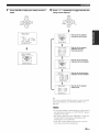
Audio signal flow
Input
Video signal flow
Input
Output
Output
HDMI
HDMI
_]
DIGITAL
AU DID
(COAXIAL)
COMPONENT
VIDEO
_(_))
DIG{TAL AUDIO
(OPT[CAL)
S VIDEO
AUD{O
VIDEO
--_-
Digital
output
--_
......
!>-
Analog
Through
output
-I>
• 2-channel as well as multi-channel PCM, Dolby Digital and
DTS signals input at the HDMI lN 1 or HDMI IN 2jack can be
output at the HDMl OUT jack only when '%UPPORT AUDIO"
is set to "OTHER" (see page 93).
• Audio signals input at the HDMI IN jacks are not (_utputat the
analog AUDlO OUT and DlGlTAL OUTPUT jacks.
Video
conversion
(see page 97)
.......
_
Component
interlace/progressive
up-conversion
(see page 98)
......
_>" HDMI interlace/progressive
up-conversion (see page 98)
• When the analog video signals arc input at the COMPONENT
VIDEO, S VIDEO and VIDEO jacks, the priority order of the
input signals is as li}llows:
1. COMPONENT VIDEO
2. S VIDEO
3. VlDEO
• The analog video signals output at the COMPONENT VIDEO
jacks can be deinterlaced from 480i (NTSC)/576i (PAL) to
480p/576p. Set CMPNT l/P to ON in MANUAL SETUP m
activate this fcatm'e (see page 98).
• Digital video signals input at the HDMl lN 1 or HDMl lN 2
jack cannot be output l'rom analog video omput jacks.
• The analog component video signals with 480i (NTSC)/576i
(PAL) of resolution are converted to the s-video or composite
video signals and output at the S VIDEO MONITOR OUT and
VIDEO MONITOR OUT jacks.
• Component interlace/progressive conversion (see page 98) and
HDMl interlace/progressive
up-conversion (see page 98) arc
available only when "V CONV." is set to "ON" (see page 97).
• Use the "HDMI l/P" parameter in "OPTION MENU" to
deinterlace the analog video signals output at Ihe HDMl OUT
jack (see page 98). When the analog video signals with 1080i or
720p of resohltion are up-converted to HDMI and output at the
HDMl OUT jack, the picture quality may worsen.
• The OSD signal is not output at the VCR 1OUT and
DVR/VCR 2 OUT jacks and is not recorded.
• The color of the letters and images in the OSD may difl'cr
depending on the input signals and your video monitol:
20 En
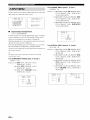
Connect your TV (or projector) to the HDMI OUT ,jack, the COMPONENT VIDEO MONITOR OUT ,jacks, the S
VIDEO MONITOR OUT jack or the VIDEO MONITOR OUT jack of this unit.
Do not connect
components
this unit or other
components
to the AC power
supply
until all connections
between
are complete.
_-'#Youcan
select to play back HDMI audio signals on this unit or on another HDMI component connected to the HDMI OUT jack on tbe
rear panel of this unit. Use the "SUPPOKF AUDIO" parameter in "SOUND MENU" to select the component to play back HDMI audio
signals (see page 93).
Noto
• Some video monitors connected to this unit via a DVI connection fail to recognize the HDMI audio/video signals being input if they
are in the standby mode. In this case, the HDMI indicator flashes irregularly.
• Set "V CONV." in "OPTION MENU" to "ON" (see page 97) to display the short message display arid parameter displays.
• Set "GRAY BACK" in "OPTION MENU" to "ON" (see page 97) to display the parameter displays.
• The SET MENU and parameter displays appear with the gray backgrom]d depending on the input video signal lormat and the setting
of the parameters in "DISPLAY SET" (see page 97).
(U.S.A.
T
,onent *,ideo_J
_
in [..___J
model)
[Video in
_
in
IV
(or projector)
indicates
recommended
indicates
alternative
connections
connections
21 En
Do not connect this unit or other components
components are complete.
to the AC power supply until all connections
between
• When "V CONV." is set to "OFF" (see page 97), be sure to make the same type of video connections as those made for your TV (see
page 21). For example, if you connected your TV to the VIDEO MONITOR OUT jack of this unit, connect yore" other components to
the VIDEO jacks.
• When "V CONV." is set to "ON" (see page 97), the converted video signals arc output only at the MONITOR OUT jacks. When
recording a source, you must make the same type of video connections between each component.
• To make a digital connection to a component other than the default component assigned to each DIGITAL INPUT or DIGITAL
OUTPUT jack, select the corresponding setting for "OPTICAL OUT", "OPTICAL IN", or "COAXIAL IN" in "110 ASSIGNMENT"
(see page 94).
• If you connect your DVD player to both the DIGITAL INPUT (OPTICAL) and the DIGITAL INPUT (COAXIAL) jacks, priority is
given to the signals input at the DIGITAL INPUT (COAXIAL) jack.
• The parameter displays do not appear when the component video signals with 720p, 1080i or 1080p are input.
• The parameter and short message displays do not appear when the component video signals with 480p/576p, 720p, 1080i or 1080p
resolutions are input and output at the VIDEO or S VIDEO MONITOR OUT jack.
•
Connecting a DVD player
DVD player
t IDM1 out
Optical out
S-video out !
;
...........
Vi_o out
;
"'°
(U.S.A.
............
22 En
indicates
recommended
indicates
alternative
connections
connections
model)
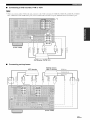
•
Connecting a DVD recorder, PVR or VCR
'_1When you connect another VCR to this unit, connect it to the VCR 1 terminals (S VIDEO IN, VIDEO IN, AUDIO IN, S VIDE()
OUT, VIDEO OUT and AUDIO OUT jacks) same as DV1UVCR 2 terminals except the DIGITAL INPUT (COAXIAL)jack.
(U.S.A.
model)
1
[---_Z
l
\
Zl
DVD recorder, PVR or VCR
•
Connecting set-top boxes
HDTV
decoder
Satellite receiver,
cable TV receiver
IIDMI out
Optical out
1
_ _ __
i
!
(U.S.A.
",
_i_
<
,o o
model)
23 En
|_om,,,=f,*iroig
_
•
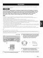
Connecting audio components
• To make a digital connection to a component other than the delhult component assigned to each the DIGITAL INPUT jack or the
DIGITAL OUTPUT jack, select the corresponding setting lor "OPTICAL OUT", "OPTICAL IN", or "COAXIAL IN" in "110
ASSIGNMENT" (see page 94).
• Connect your turntable to the GND terminal of this unit to reduce noise in the signal. However, you may hear less noise without the
connection to the GND terminal lor some tm'ntables.
• The PHONO jacks arc only compatible with a turntable with an MM or a high-output MC cartridge. To connect a turntable with a lowoutput MC cartridge to the PHONO jacks, use an in-line boosting transformer or an MC-head amplifier.
• When you connect both the DIGITAL INPUT (OPTICAL)jack
and the DIGITAL INPUT (COAXIAL)jack
to an audio component,
the priority is given to the DIGITAL INPUT (COAXIAL)jack.
Audio out
_ Optical in
CD recorder
(U.S.A.
model)
r
Ground
kudio
I
i Coaxial
1
I Optical
Audk)
_Audio
out
_in
1
) optic_l in
Turntable
24 En
CD player
MD recorder or
tape deck
•
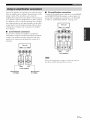
Connecting
an external amplifier
This unit has more than enough power for any home use.
However, if you want to add more power to the speaker
output or if you want to use another amplifier, connect an
external amplifier to the PIlE OUT ,jacks.
• When you make connections to the PRE OUT jacks, do not
make connections to the SPEAKERS terminals.
• The signals output at the FRONT PRE OUT and CENTER PRE
OUT jacks are affected by the TONE CONTROL settings {see
page 50).
• Each PRE OUT jack outputs the same channel signals as the
corresponding SPEAKERS terminals.
• Adjust the volume level of the subwoofer with the control on
the subwoofer (see page 51 ).
• Some signals may not be output at the SUBWOOFER PRE
OUT jack depending on the settings for "SPEAKER SET" (see
page 87) and "LFE/BASS OUT" (see page 87).
©
0)
i @
@
CENTER
®
PRE OUT jack
Center channel output jack.
FRONT
Front channel
@
output
SURROUND
Surround
@
PRE OUT jacks
channel
jacks.
PRE OUT jacks
output jacks.
SURROUND
BACK/PRESENCE
PRE OUT
jacks
Surround
back or presence
you only connect
back channel,
channel
one external
connect
output jacks.
amplifier
it to the SINGLE
When
for the surround
(SB),jack.
"4:-• Set the "S B L/R SP" to "LRGx2". "LRGxI'. "SMLx2" or
"SMLx 1" and "PRESENCE SP" to "NONE" (see page 89) to
output the surround back chamrel signals at SURROUND
BACK/PRESENCE PRE OUT jacks.
• Set the "PRESENCE SP" to "YES" and "SB L/R SP" to
"NONE" (see page 89) to output the presence channel signals at
SURROUND BACK/PRESENCE PRE OUT jacks.
@
SUBWOOFER
Connect
a subwoofer
PRE OUT jack
with a built-in
amplifier.
25 En
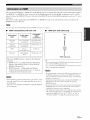
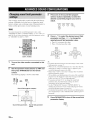
This unit is equipped
SUBWOOFER)
with 6 additional
for discrete
input jacks
multi-channel
(left and right FRONT,
input from a multi-format
CENTER,
player,
left and right SURROUND
external
decoder,
sound
processor
and
or
pre-amplifier.
If you set "INPUT
in MUUFI
Connect
match
CH" to "8ch" in _'MULTI
CH SET (see page 96) together
the output jacks
on your multi-format
the left and right outputs
CH SET" (see page 96), you can use the input jacks
with the MULTI
player
CH tNPUT jacks
or external
to the left and right input jacks
decoder
to input 8-channel
assigned
to the MULTI CH INPUT
for the front and surround
as _'FRONT"
signals.
jacks.
Be sure to
channels.
Noto :
• When you select the component connected to the MUKI'I CH INPUT jacks as the input source/see page 41), this unit automatically
turns oil the digital sound lield processor, and you cannot select sound field programs.
• This unit does not redirect signals input at the MULTI CH INPUT jacks to acc(nnmodate lor missing speakers. We recommend that
you connect at least a 5. l-channel speaker system belore using this leatore.
For 6-channel
input
For 8-channel
input
CEmER _RO_{_CH_SURP_U_D
i
i iLi
iRi
iL
R_
i
i i
{Li iR
Multi-format playeff
External decoder
Multi-format player/
External decoder
'_1 The analog audio input jacks assigned as "FRONT"
"MULTI CH SET" (see page 96).
26 En
in
_Oh'h'l_tiiOhy
This unit is equipped
with the DOCK
panel that allows you to connect
universal
where
dock (such as the YDS-10,
you can station
YAMAHA
iPod universal
separately)
to the DOCK
remote
on the rear
iPod
control.
playback
of
Connect
a
dock (such as the YDS- 10, sold
terminal
Be sure to turn off the volume of this unit and
other components
before making connections.
on the rear panel of this
cable.
Do not connect this unit to the AC power supply
until all connections between components are
complete.
YAMAHA
Use the VIDEO AUXjacks on the front panel to connect a
game console or a video camera to this unit.
sold separately)
your iPod and control
your iPod using the supplied
unit using its dedicated
terminal
a YAMAHA
iPod universal
(such as the YDS-10,
sold separately)
The audio signals input at the DOCK terminal on the rear panel
take priority over the ones input at the VIDEO AUX jacks.
(U.S.A.
model)
dock
S-Vide(
IVide
output
ioutp
Game console or
video camera
27 En
Both FM and AM indoor antennas
unit. Connect
each antenna
terminals,
in general,
sufficient
signal
are supplied
correctly
with this
Press and hold the tab of the AM ANT
terminal.
to the designated
these antennas
should
provide
strength.
• Be sure to set the tm_er frequency step (Asia and General
models only) according to the frequency spacing in your area
(see page 119).
• The AM loop antenna should be phtced away from this refit.
• The AM loop antenna should always be connected, even if an
outdoor AM antenna is connected to this refit.
• A properly installed omdoor antenna provides clearer reception
than an indoor one. If you experience poor reception quality,
install an outdoor antenna. Consult the nearest authorized
YAMAHA dealer or service center about outdoor antennas.
Indoor FM _
antenna H
c_=
J_
(supplied)
_
_
AM loop
antenna
(supplied)
Release the tab of the AM ANT terminal.
%
:: _;_>S)"
Insert one of the AM loop antenna lead wires
into the AM ANT terminal.
N;;;;s#
l
(U.S.A. model)
Outdoor
AM
antenna
Use a 5 to 1(t m (16.4
to 32.8
_1 vinyl-covered
wire
extended
outdoors
fiom
a
window.
Ground (GND terminal)
For maximum sa_bty and minimum intcrfbrcnce, connect the
antenna GND terminal to a good earth ground. A good earth
ground is a metal stake driven into moist earth.
•
Connecting the AM loop antenna
1
Set up the AM loop
28 En
antenna.
Repeat steps 2 through 4 to connect the
other lead wire to the GND terminal.
Once you have properly connected the AM loop antenna to
this refit, orient the AM loop antenna for the best reception
when you tune into AM stations {see page 54).
_oli'li'l-_tiioli'_
•
Connecting the AC power cable
Use the supplied AC cable. Do not use other AC power cables as doing so may result in fire or
electrical shock.
Plug the supplied AC power cable into the AC inlet after ;ill other connections are complete, then phlg the AC power
cable into an AC wall outlet.
(U.S.A.
model)
_
•
To the AC wall
outlet
VOLTAGE SELECTOR
•
(Asia and General models only)
U.K. and Australia models .....................................
1 outlet
Korea model ...............................................................
None
Other models .........................................................
2 outlets
The VOLTAGE SELECTOR on the rear panel of
this unit must be set for your local voltage
BEFORE plugging the power cable into the AC
wall outlet. Improper setting of the VOLTAGE
SELECTOR may cause damage to this unit and
create a potential fire hazard.
Rotate the VOLTAGE SELECTOR clockwise or
counterclockwise to the correct position using a
straight slot screwdriver.
Voltages are as follows:
Asia model ......................... 2201230 240 V AC, 50160 Hz
General model ...... 110112012201230 240 V AC, 50160 Hz
AC OUTLET(S) (SWITCHED)
Use these outlet(s) to supply power to any connected
components. Connect the power cable of your other
components to these outlet(s). Power to these outlet(s) is
supplied when this unit is turned on. However, power to
these outlet(s) is cut off when this unit is turned off. For
information on the maximum power or the total power
consumption of the components that can be connected to
these outlet(s), see "SPECIFICATIONS" on page 136.
Memory back-up
The memory back-up circuit prevents the stored data
from being lost even if this unit is in the standby mode.
However, the stored data will be lost in case the power
cable is disconnected from the AC wall outlet or if the
power supply is cut off"for more than one week.
VOLTAGE
SELECTOR
........
Voltage
indication
29 En
I_.l,v,v=f._ir.]g_
Press STRAIGHT on the front panel
repeatedly to select "6_QMIN'.
The following display appears in the front panel
display.
If you are to use 6 ohm speakers, set "SPEAKER
IMP." to "6_2MIN" as follows BEFORE using this
unit. 4 ohm speakers can be also used as the
front speakers.
(U.S.A.
STRA_H*
model)
:5 i:::'
E i:::i
i::;E i:;;: i Mi:::',,
_:;:j"ihi T M
2,5
3
5
2,4
Press MASTER ON/OFF on the front panel to
release it outward to the OFF position to save
the new setting and turn off this unit.
Make sure this unit is turned off.
See page 31 for details about turning on or oIT this
unit.
Press and hold STRAIGHT on the front panel
and then press MASTER ON/OFF inward to
the ON position to turn on this unit.
This unit turns on, and the advanced setup menu
appears in the front panel display.
While holding
down
STRA_HT_
_
_
Rotate the PROGRAM selector on the front
panel to select "SPEAKER IMP.".
The following display appears in the front panel
display.
PROGRAM
=""r": r" =%i,," r" i":
.D r" C, i"i r.,. C. r::.
30 En
T i,,,i r":
.i, i'i i ,,
The setting you made is reflected next time you turn on this
unit.
_qiTi'l"i_t?li'_
When
all connections
are
complete,
turn
on this
unit.
MAIN ZONE ON/OFF
(U,S,A,
MASTER
•
(U.S.A.
Turning on this unit
you turns on this unit by pressing
OFF, the main zone is turned
•
MASTER
ON/
Turning on the main zone from the
standby mode
Press MAIN ZONE ON/OFF on the front
panel (or POWER on the remote control) to
turn on the main zone.
on.
MAIN
Front
Front panel
•
model)
ON/OFF
Press MASTER ON/OFF on the front panel
inward to the ON position to turn on this
unit.
When
model)
ZONE
panel
Remote
control
Turning off this unit
•
Press MASTER ON/OFF on the front panel
again to release it outward to the OFF
position to turn off this unit,
Set the main zone to the standby mode
Press MAIN ZONE ON/OFF on the front
panel (or STANDBY on the remote control)
to set the main zone to the standby mode.
MAIN
ZONE
Front panel
Front panel
Remote
control
• MAIN ZONE ON/OFF on the fl'ont panel as well as POWER
and STANDBY on the remote control are operational only
when MASTEP. ON/OFF is pressed inward to the ON position.
• As usual, we recommend using the standby mode to turn off this
unit.
31 En
This unit employs the YPAO (YAMAHA
Parametric
Room Acoustic Optimizer)
technology
which lets you avoid
troublesome
listening-based
speaker setup and achieves highly accurate sound adjustments
automatically.
The supplied
optimizer
microphone
collects
and this unit analyzes
the sound
your speakers
produce
in your actual
listening
environment.
Once
you have connected
microphone
to the OFFIMIZER
panel and have placed
listening
the supplied
room,
MIC jack on the front
it in a suitable
run "AUTO
optimizer
SETUP"
location
Connect the supplied optimizer microphone
to the OPTIMIZER MIC jack on the front
panel.
in your
in the OSD or in the
(U.S.A.
model)
front panel display.
• Be advised that it is normal li)r loud test tones to be output
during the "AUTO SETUP" procedure.
• To achieve the best results, make sure the room is as quiet as
possible while the "AUTO SETUP" procedure is in progress. If
there is too much ambient noise, the results may not be
safislhctory.
microphone
_.,#.
• You can run "AUTO SETUP" using the system menu that
appears in the OSD or in tbe front panel display. This manual
uses the OSD illustrations to explain the "AUTO SETUP"
procedure.
• If an error occurs during the "AUTO SETUP" procedure and an
error or warning message appears in the OSD or in the front
panel display, see the "AUTO SETUP" section in
"TROUBLESHOOTING"
on pages 128 and 129 lor a complete
list of error and warning messages and proper remedies.
• The initial setting for each parameter is indicated in bold.
• If the volume level and the crossover frequency of your
Place the optimizer microphone at your
normal listening position on a flat level
surface with the omni-directional
microphone heading upward.
Optimizermicrophone
subwoolier can be adjusted, set the volume level m about half
way (or slightly less) and set the crossover frequency u_ the
maximum.
14
(U.S.A.
32 E,
model)
It is recommended that you use a tripod (etc.) to affix tbe
optimizer microphone at the same height as your ears would be
when you are seated in your listening position. You can use a 6
mm diameter screw to fix the optimizer microphone to a tripod
(etc.).
Make sure of the following check points
7
before starting the AUTO SETUP operations.
• Speakers are connected appropriately.
• Supplied optimizer microphone is connected to this
unit and placed appropriately.
• Headphones are disconnected fi'om this unit.
• The room is sufficiently quiet.
• The video monitor connected to this unit is turned on.
Set the operation mode selector to AMP and
then press SET MENU to enter "SET MENU".
The top "SET MENU" display appears in the OSD.
=_FT
k4FL Ii I
+ .gUTO SETLIF'
.MI_IqUFILSETUP
.SIGH#L
IMEO
Speaker wiring i.di R i ii(!!i
Checks which speakers are connected and the
polarity of each speaker.
Choices: CHECK, SKIP
• Select "CHECK" to automatically check and adjust
the item.
• Select "SKIP" to skip the item and perform no
acljustments.
Press ENTER to enter "AUTO SETUP".
The "AUTO:MENU" display appears in the OSD.
i
,MJ
PJi
'?="l_
_L_=
i']r_i'9o,
k_P_
Ii i
+ SETLIP ....... I:IUT
0
i,]
IR IM g ..... EHEC:K
DISTPMEE, _ _C:HEC:K
SIZE ....... EHEEK
EQ .......
I_glTLIR#L
LEUEL. ..... CHEEK
STPRT
I ,,k]/I"_'] _U_-/ [/ot,!n
['<]/[_']
;SeiecL
Press < / _> to select "SETUP".
PRESETmH
',
Choices: AUTO, RELOAD
• Select "AUTO" to automatically run the entire
"AUTO SETUP" procedure.
• Select "RELOAD" to reload the last "AUTO
SETUP" settings and override the previous
settings. When you select "RELOAD", the
previous auto setup result appears in the OSD. See
step 7 on page 34 and carry out the operations.
is available
This unit performs the following checks:
Speaker size :!!!;
i Z i!!!i
Checks the frequency response of each speaker and
sets the appropriate low-frequency crossover for each
channel.
E.,k]
/ ['t_']
_Ug,'Dc,kuq
EEMTER ]; En<:er
"I_.ELOAD"
H_ i = =, ,iL =I
SETLIP ....... I:IUTO
+ klIRIlqG..... EIqEC:K
D [STIOI4C;E...
C:Iq
EC:I{
SIZE ....... EHEC:K
EQ .......
14glTLIIRJ_L
LEUEL. ..... C:HEC:K
STPRT
[,,k]/[',_' ] _UF, [icik,q
[,_]/[i_]:
Seiec%
Speaker distance [:,]ISFf::IM(];i!!!I
Checks the distance of each speaker from the
listening position and at!justs the timing of each
channel.
2¢,i H_i'!U
A E/CA_
Press A / _7repeatedly to select "WIRING",
"DISTANCE", "SIZE", "EQ", or "LEVEL".
( nl 3 when
you haxe previously
run
Parametric equalizer level i!!!);!
Adjusts the frequency and the parametric equalizer
level of each channel to reduce coloration across the
channels and create a cohesive sound field. This is
particularly important if"you use different brands or
sizes of speakers for some channels or have a room
with unique sonic characteristics. In addition, the
fi'equency response of each channel is adjusted in
accordance with the sound output fi'om your fi'ont
speakers.
Choices: NATURAL, FLAT, FRONT, SKIP
• Select "NATURAL" to average out the fi'equency
response of all speakers with higher fi'equencies
being less emphasized. Recommended if the FLAT
setting sounds a little harsh.
• Select "FLAT" to average the fi'equency response
of all speakers. Recommended if all of your
speakers are of similar quality.
• Select "FRONT" to adjust the fi'equency response
of each speaker in accordance with the sound of
your fi'ont speakers. Recommended if your fi'ont
speakers are of much higher quality than your other
speakers.
• Select "SKIP" to skip the selected item and
perform no adjustments.
"AUTO SETUP" and confirmed the resuhs.
33 En
I_IWiIPi-'i_lq
'
Volume
level
i F:UF:I
Checks and adjusts the vohune
Choices: CHECK,
SKIP
• Select "CHECK"
this item.
• Select
"SKIP"
level of each speaker.
to automatically
check and adjust
to skip this item and perform
no
adjustments.
Press _7to select "START" and then press
ENTER to start the setup procedure.
This unit starts the auto setup procedure. Loud test
tones are output from each speaker during the auto
setup procedure. Once all items are set, the
"RESULT:EXIT" display appears in the OSD.
@-@
PRESETI_H
A
PRESET/_.
A
• During the auto setup procedure, do not perlorm any
operation on this unit.
• Wc recommend getting out of the room while this unit is in
the aLttosetup procedure. It takes approximately 3 minutes
for this unit to complete the auto setup procedure.
The display changes as follows.
SETUP, ...... gUTO
k_IRiHG ..... CHEC:K
D ISTPMC:E... CHECK
SIZE .......
CHEC:K
Eg!.......
14rITLIIRPL
LEUEL. .....
C:HEL-,K
÷ STPRT
[ A] s' [_'] ; UF DONIq
,.,_ i=ji,Tpi
==,111%=,i/
4 M J,.=°,Ng°o,
I NI TI gL IZ 11'115
÷ FIRE C:HEC:K
Hgllq CHECK
Eg!LIPLiZ II_J_
LEUEL
CHECK
CH=C:EHTER
iIill .........
L,_,]
_ Exit
Rr::_L]L.,
D"=..
÷ RESLILT
SP
_
5,'4/C_.1
DiST_
Id._?i 17.CIft
LUL _ .-9.¢/
+6.SdEl
>SET
C:gNC:EL
I,,_,] ['_*]_ Ur_ '])own
I EIq] ER] _Enter
34 En
The results displayed under "RESULT" are as
follows.
Number of speakers :!!!;l:::'
Displays the number of speakers connected to this
unit in the following order:
Front/Back/Subwoofer
Speaker distance i) :[:!!!;]
Displays the speaker distance from the listening
position in the following order:
Closest speaker distance/Farthest speaker distance
Speaker level l....i.)l
....
Displays the speaker output level in the following
order:
Lowest speaker output level/Highest speaker output
level
• If "E-10:INTERNAL
ERROR" appears during the testing
procedure, restart fl-om step 4.
• If you selected "RELOAD" in step 4, no test tones arc
output.
• If an error occurs during the "AUTO:CHECK" procedure,
the setup procedure is canceled and an error screen
appem's. For details, see "If an error screen appears" on
page 36.
• When this unit detects potcnfal problems during the
"AUTO SETUP" procedure, "WARNING" and the
number of warning messages appears in the above of
"RESUUF' (see page 37).
• Depending on the listening environment, "SWFR
PHASE:REV" appears during the "AUTO:CHECK"
procedure and "SUBWOOFER PHASE" in "SOUND
MENU" (see page 89) is antomatically set to
"REVERSE".
Press ENTER to display the setup results in
detail.
10
Press <:I / C> repeatedly to toggle
between the
setup result displays.
PRES[TI_H
A E/CA_.
r_¢
T_
Results
It
5
FROIqT L .......
÷ REEULT
EF'
;
5/4/g_
I
DIET;
IdJ]i
17J],ft
Liq_ _ "-%0' +6.SdB
>SET
CPIE:EL
[i] /['_']
_ UF ,'[lo_,aq
[EMTER ]_Enter
t
PROFIT
I_, ....
"-
[_]' [l_] _ Sele,:+
[ ENTER ] _ Ret i_rn
Results
iESLLT',[:iSTAE:Ei
distance
FRCI'T L.. 14,0;t
LEI'iTE_, 17_L);t
FFOIqT R- - 15,0;t
PRI% L, - - 17, L_ft
F;BI' :, R, -, 17,0;t
n
_,I,
of the speaker
connection and wiring
C!K
[_], [I_3 Sele,:
EEl, TEF ] Rebrr
listening
of the speaker
from the
position
[
I
:D:i
FRONT L. .....
] _
[EI4TER]
Results of the frequency
response
of each speaker
[ T_¢f?= r
LPG
J ,, :,=1 .- .....
RetuJ
h
[._], [1_] : :ele,:t
[EIqTER] Re i_
rr, = ' T%",
CEI'TEF
i 10@_z.
- - +2_
dE
4! 1,kHz.
- +2,
5 l _ dkHz..
-3_
d 2_ _Hz
.+2_
/! 1Uk Iz +2,
[_], [_]
tele,:
[ E_TER ] : ReL L_
dE
5dE
,B
ESLLT:
LEiE_t
FROI'T L,, +I,L_dE
CEt_TER .......
l, 5dE
FRC I'!T R,--%,
dB
PRI%, B -..
Results of the parametric
equalizer of each speaker
[
Results of the speaker
output level
+i ,PJIE
[_], [l_] 2ele,:
[ El' TER ] Retl_
L
If you are not satisfied with the _csnlts or want to manually
adjust each parameter, run "MANUAL
page 84).
SETUP" (see
• If you change speakers, speaker positions, or the layout of
your listening enviromnent, mn "AUTO SETUP" again to
rccalibrate your system.
• The distances displayed in the "DISTANCE" resuhs may
be longer than the actual distance depending on the
characteristics of your subwoofcr.
• In the "EQ" results, different values may be set for the
same band to provide finer adjustments.
35 En
I_IWiJpi-'i=/iq'
•
11
If an error screen appears
Press ENTER to return to the top
"RESULT:EXIT"
Press A / V / < / E> to select "RETRY" or "EXIT"
and then press ENTER.
The following display is an example where "E-9:USER
CANCEL" appears in the OSD.
display.
÷ REEULT
==F' :
5/4/0.
I
DiST: I_,0/ 17,Oft
LUL : .-9,€_' +6,SdE'
>SET
CAU[:EL
[,a] IT] :U_: '[lown
[EUTER ]_Enter
Yr r_P_r_
EF,F
....
E-9:
_rl'_l
12
Make sure the pointer is pointing at "SET"
and "CANCEL" and then press < / E> to
select "SET" or "CANCEL".
@
PRES_I_H
A E/CA_
RESLtI_T
SP
:
5,4/0_ 1
BiST: 14_0,' 17,Oft
LUL : -'?_e!
+6,,SdE:
÷ b'EET
[;FIHCEL
'.
[ EHTER ] _Enter
SET, CANCEL
Choices:
• Select "SET" to confirm
the "AUTO SETUP"
results.
• Select "CANCEL"
to cancel
the "AUTO SETUP"
results.
13
Press ENTER to confirm your selection.
The top "SET MENU" display appears in the OSD.
':,UPi-E!
+
,AUTO SETUP
,HAI'IUAL SETUP
,S iGIfiAL llfiFCl
[&] / ["_] : LIj:/E/own
[EHTER ] :ErrLer
14
Press SET MENU to exit from "SET MENU".
S_E_U
• Alter you have completed the "AUTO SETUP" procedure, be
sureto disconnect the optimizer microphone.
• The optimizer microphone is sensitive to heat. Keep it away
fl'om direct
36 En
sunlight
and do not place
it on top of tllis unit.
UEER CAME:EL
[h=q-i a f. oFer_=l't.e
_£ Uric
_
i Orh,
+ _'RETR','
EXIT
[ ] [ _,,:,__....
[ EHTER ] : En't eJ....
Choices: RETRY, EXIT
• Select "RETRY" to retry the "AUTO SETUP"
procedure.
• Select "EXIT" to exit from the "AUTO SETUP"
procedure.
•
If"WARNING"
appears
When this unit detects potential prohlems during the
"AUTO SETUP" procedure, "WARNING" appears in the
"RESUUF:EXIT" display. Check the warning messages to
correct your speaker settings.
Warnings differ h'om errors in that warnings do not cancel the
"AUTO SETUP" procedure.
Make sure the pointer is pointing at
"WARNING" and then press ENTER to
disptay the detailed information about the
warning.
The number on the right of"WARNING"
the number of warning messages.
indicates
_,C:,UL
i _C?:=
1i
÷ I,JPRI_iHL_
(3:,
RESLILT
SP
_
5'4'0,1
DiST_ J4,0,
17.Efft
LUL _ -9.g, +6.5dB
_-SET C:AHC:EL
[ EIq]ER ] _Enter
2
Press <lIE> repeatedly to toggle between the
warning displays.
i h=_hU?UP,= ii
I,I,IHW'iii'gj, i,iF"
::: OUT OF PHASE ::_
Re, ,el :a.e 17.:harlrlei
FL
-CEI4TER
F'I.
F'R
SL
SIR
SBL
SBR
['_]'D_] ; Select
[EI4TER]
_ En'teJ ....
• For details about each warning message, see the "AUTO
SETUP" section in "TFt.OUBLESHOOTING"
on
page 128.
• When the corresponding warning message is not
applicable to a speaker," " is displayed instead.
3
Press ENTER to return to the top
"RESULT:EXIT"
display.
r=.'_ =i Ii T = Y_,,; ? T
F,C:u_, =b'=.,
WgRIqII,/G (3)
REEULT
SP
_
5'4'0,1
DiST_ 14_E_i 17.O_t
LUL _ .-%g' +6.5dB
÷ I_"SET CPlIC:EL
[A],'[',_
]_:
UFiDC,_m
[ EHTER ] _Enter
37 En
Extreme caution should be exercised when you play back CDs encoded in DTS. If you play back a CD
encoded in DTS on a DTS-incompatible CD player, you will only hear some unwanted noise that may
damage your speakers. Check whether your CD player supports CDs encoded in DTS. Also, check the
sound output level of your CD player before you play back a CD encoded in DTS.
-"4¢'To play DTS-encoded ('Ds when using a digital audio connection set "DE('ODER MODE" in "INPUT MENU" to "DTS" belore the
playback (see page 96).
Rotate the INPUT selector on the front panel
(or set the operation mode selector to AMP
(U.S.A.
model
and then press one of the input selector
buttons on the remote control) to select the
desired input source.
iNPUT
2
Front
5
panel
or
"U"U "©"{5
Remote
control
The name of the currently selected input source
appears in the fl'ont panel display and in the OSD for
a few seconds.
(U.S.A.
model)
Available input sources
MDZAPe
C_R CD _
Turn on the video monitor connected to this
unit.
DWVCR__RI C_T
DW _DVD
.....i
i,ll:::'ir] ',:
• See page 42 to display the input source inlormation.
• Youcan display a gray background in the OSD when there
isno video signal being input by setting "GRAY BACK"
in"OPTION MENU" to "AUTO" (see page 97).
• Youcan change the display settings by using "SHORT
MESSAGE" parameter in"DISPLAY SET". See pages 98
lot details.
38 En
_Um_
_
_]
[:,i..i[:,T
Currently
selected
input
source
For details about controlling XM Satellite Radio when
"XM" is selected as the input source, see page 65.
Start
playback
component
on the selected
or select
source
a broadcast
• Refer to the operating
station.
instructitms
Sound field programs and the Compressed Music Enhancer
mode cannot be selected when the component connected to
the MULTI CH INPUT jacks is selected as the input source
(see page 41) arid Audio input jack select is set to
"ANALOG" (see page 40).
for the source
component.
• See page 54 for details
• See page 65 for details
tuning
about tuning instructions.
about XM Satellite Radio
--'4_'--
instructions.
• Choose a sound field program based on your listening
preference, not merely on the name of the program.
• When yOLIselect an input source, this unit automatically
selects the last sound field progrmn used with the
corresponding input source.
• To display information about the currently selected input
source in the OSD, see page 76 for details.
Rotate VOLUME on the front panel (or press
VOLUME +/- on the remote control) to adjust
the volume to the desired output level.
•
Guideto contents
When you want to...
Front
panel
Remote
control
See
page
Enjoy pure hi-fi stereo sound
50
Adjust the tonal quality ol the front speakers
50
Enjoy the compressed music sources in enhanced
52
sound
See page 51 to adjust the level of each speaker.
Rotate
the PROGRAM
panel (or press
program
control
sound
on the front
one of the sound
selector
buttons
repeatedly)
field
selector
field
on the remote
to select
the desired
program.
The name of the selected
sound
field program
in the front panel display
and in the OSD. See
page 45 for details about
sound field programs.
PROGRAM
Edit parameters of sound field programs
76
Ei_joythe sources which have wide dynamic range at
night
53
Use headphones
4I
Enjoy multi-channel sources in 2-channel stereo
5I
Select a decoder to play back sources with
80
Set this unit to the standby mode automatically
43
appears
Q_
Front panel
Remote control
)
Currently selected sound field program category
I
H0 LJi i::
:iii;,::.
:i.-l:: :i.
I
Currently selected sound field program
39 En
IRliV.1_:_pf,
i'_ii"r'l%
Automatically
selects
the following
( 1) HDMI
This unit comes
feature
(Audio
with a variety
of input jacks.
input .jack select)
Use this
to switch the input jack
assigned
to an input source when more than one .jacks are
assigned
to an input source.
iii....ii._.
input signals
in
order:
(2) Digital
signals
(3) Analog
signals
Selects
only HDMI
HDMI
signals
signals.
When
are not input, no sound
is output.
i=._'11"1=..,
_ ..._"li::) ....
-#.
• We recommend setting Audio input jack select u_ "AUTO" in
most cases.
(1) Digital
INPUT
(2) Digital
selects
order:
signals
COAXIAL
• You can adjust the default Audio input jack select of this unit by
using "AUDIO SELECT" in "OPTION MENU" (see page 99).
Rotate the INPUT selector on the front panel
(or press one of the input selector buttons on
the remote control) to select the desired
input source.
Automatically
the following
input signals
in
input at the
jack.
signals
input at the
OPTICAL jack.
When no signals are input, no sound
is
output.
¢"_M _"d
_"ff:::
Selects
only analog
analog
signals
signals.
If no
are input, no sound is
output.
Note
or
000%
Front panel
Remote control
This lbature is not available when no digital input jack
(OPTICAL, COAXIAL and HDMI) are assigned. In
addition, HDMI is not available as an Audio input jack
select setting when the HDMl IN 1 and HDMI IN 2jacks
are not used. Use "l/O ASSIGNMENT" in "INPUT
MENU" to reassign the respective input jack (see page 94).
Press AUDIO SELECT on the front panel (or
AUDIO SEL on the remote control) repeatedly
to select the desired Audio input jack select
setting.
AUD_
SE_CT
AUDIO SEL
% or %
Available input sources
i::i,,:iii:iiii:L.
:: i::iUT07
Currently selected
Audio input jack
select setting
40 En
ilw.l_:_Pli
Use this feature
MULTI
to select
CH INPUT
the component
connected
to the
jacks (see page 26) as the input
SOLlrce.
Connect a pair of headphones with a stereo
analog audio cable plug to the PHONES jack on
the front panel.
Rotate the input selector on the front panel to
select MULTI CH INPUT (or MULTI CH IN on the
remote control).
MULTIC_I_
or
Front panel
Remote control
Use "MUUI'I CH SET" menu in "INPUT MENU" to set the
parameters lor MULTI CH INPUT/see
page 96).
Sound field programs and the Compressed
When you select a sound lield program, SILENT CINEMA mode
activates automatically (see page 49)
Music Enhancer mode
cannot be selected \_hen the component connected to the MUUFI
CH INPUT jacks is selected as the input source and Audio input
jack select is set to "ANALOG" (see page 40).
• When you connect headphones,
speaker terminals.
no signals are output at the
• When the component connected to the MUUFI CH INPUT
jacks of this refit is selected as the input source and Audio input
jack select is set to "ANALOG" (see page 40), only the signals
input at FRONT jacks are output fi'om the connected
headphones.
• All Dolby Digital and DTS audio signals are mixed down to the
left and right headphone channels.
Press MUTE on the remote control to mute the
audio output. Press MUTE again to resume the
audio output.
%
• You can also rotate VOLUME on the front panel or press
VOLUME +1 on the remote control to resume the audio
output.
• You can adjust the muting level by using the "MUTE TYPE"
parameter in "SOUND MENU" (see page 93).
• The MUTE indicator flashes in the fi'ont panel display when the
audio output is muted and disappears from the li-ont panel
display when the audio output is resumed.
41 En
IRliV.1_:_Df,
•
Signal format
li:::''"
_,..'_'..1
C, i')_,",
Ir"l "fI '
Signal format. When this unit cannot detect a digital
signal, it atttomatically switcbes to analog input.
YOUcan display the format, sampling frequency, channel,
bit rate and flag data of tbe current input signal.
1
Audio information
Set the operation mode selector to AMP and
"---" appears when this unit cannot detect any signals.
then press SET MENU on the remote control.
Tbe top "SET MENU" display appears in the OSD.
Sampling frequency
SI::iMF'L.
i }.i(!)
The number of samples per second taken from a
continuous signal to make a discrete signal.
E,E.i i']gi'gJ
÷ ,gLIT0 SETLIp
, HI:IHLlgl_
SETUP
, SiGIqgL If,
IF0
"---" appears when this unit cannot detect the sampling
lrequency.
[ ENTER _ :En<:er
Channel
Tbe number of source channels in the input signal
(fl'ont/surround/LFE). For example, a multi-channel
soundtrack with 3 front channels, 2 surround
channels and LFE, is displayed as "31210.1".
Press V repeatedly to select "SIGNAL INFO"
and then press ENTER.
Tbe audio information about the input source appears
in the OSD.
"---" appears
PRESET_H
i=.i.J,...i
i..ii..ii::?
i
u.q _r"l H i ".q,..%,
PRESET/_H
Bit rate
when
there
is no source
channel
axailable.
_:::,
T"i=i:::,("l"i"i:::"
The number of bits passing a given point per second.
*X
*X
"---" appears when this unit cannot detect the bit rate.
Dialogue normalization
level
[:,]IAL..C,3
The dialogue normalization level preset to the current
input Dolby Digital and DTS signal.
Press A / V repeatedly to navigate the cursor
in the OSD and press <S / [:> to toggle
between the audio and video information
Flag i:::i..J:::I(!!i
Hag dataencodedinDTS, DolbyDigital,
orPCM
signals that cue this unit to automatically switch
decoders.
displays.
@
_aESEr<_H
pRESE_H
•
HDMI Signal Type H[:,M]I S]i(!!iiqI::ii
....
Type of"the HDMI signals input or output at the
HDMI IN/OUT.jacks of this unit.
HDMI Resolution
Navigatingthe cursor
4
Selecting
the audio or
video information
Press SET MENU on the remote control again
to exit from "SET MENU".
set _E_
42 En
Video information
IiI:::,M:[RES,,
Resolution of the HDMI signals input or output at the
HDMI IN/OUT.jacks of this unit.
Analog Resolution AMI::ii.C,3RES..
Resohttion of the analog signals input or output at the
video jacks of this unit.
HDMI Error
HE:,M
]: ERRs?F;?.
Error message for HDMI sources or connected
HDMI devices. See page 127 for details.
i/w.l_:_Pli
Press SLEEP on the remote control
repeatedly to set the amount of time.
Each time you press SLEEP, the fi'ont panel display
changes as shown below.
You can combine a video image fi'om a video source with
sound from an audio source. For example, you can enjoy
listening to classical music while viewing beautififl
scenery fi'om the video source on the video monitor.
SLEEP
%
Press the input selector buttons on the remote
control to select a video source and then an
audio source.
The SLEEP indicator flashes while you are switching
the amount of time for the sleep timer. Once the sleep
timer is set, the SLEEP indicator lights up in the fi'ont
panel display, and the display returns to the selected
sound field program.
Q
L
"Z'"
•"-i
i"'i
:
.i ."-:":..."
:DL.iZ tZ t''=
.i..=:;):::t"i .I _"I =,
Set the "BGV" parameter in the "MULTI CH SET" menu to the
desired setting to select the default background video input source
of the MULTICH INPUT sources (see page 96).
Fla_shes
2: I i"::i".I
.i. "i" i
Use this feature
standby
to automatically
set the main zone to the
mode after a certain amount
timer is useful when you are going
is playing
or recording
automatically
connected
1
turns
a source.
Lights
up
The sleep timer also
off any external
to the AC OUTLET(S)
of time. The sleep
to sleep while this unit
components
•
Canceling
the sleep
timer
(see page 29).
Press one of the input selector buttons on
the remote control to select the desired input
source.
Press SLEEP on the remote control repeatedly
until "SLEEP OFF" appears in the front panel
display.
SLEEP
&
%
C)(D
Start playback on the selected source
component or select a broadcast station.
P,efer to the operating instructions for the source
component.
See page 54 for details about tuning instructions.
•"-i
r'- r"= r
:D
L.iZ
tZ t''=
:": i"= i....
L.
t" r"
0,
, %
Disappears
The SLEEP indicator turns off, and "SLEEP Ot"F"
disappears fi'om the fi'ont panel display, after a few
seconds.
The sleep timer setting can also be canceled by pressing
STANDBY on the remote control (or MAIN ZONE ON/OFF on
the fl'ont panel) to set the main zone to the standby mode.
43 En
This unit is equipped with a variety of precise digital decoders that allow you to enjoy multi-channel
playback from
almost any stereo or multi-channel
sound source. This unit is also equipped with a YAMAHA
digital sound field
processing
(DSP)
chip containing
several
sound
field programs
which you can use to enhance
your playback
experience.
_.,#.
• When you set the "DECODER MODE" parameter in "lNPUT MENU" to "AUTO", this unit selects the appropriate digital decoder
according to the input signal.
• The YAMAHA ClNEMA DSP modes are compatible with all Dolby Digital, DTS, and Dolby Surround sources.
• The YAMAHA HiFi DSP sound field programs recreate real-world acoustic environments made li-om precise measurements taken in
actual concert halls, music venues, movie theaters,
etc. Thus, you may notice variations in tile strength of the reflections coming from
the front, back, lel) and right.
• You can change sound field parameters. See page 76 lor details.
Notes
• When you select an input source, this unit automatically selects the last sound field program used with the corresponding input source.
• Sound field programs cannot be selected when the component connectcd to the MULTl CH lNPUT jacks is selected as the input
source (see page 41) and Audio input jack select is set to "ANALOG" (see page 40).
• When you play back DSD sources with any sound field program, this unit converts the DSD signals to PCM signals and then applies
the selected program.
• When you play back DTS 96/24 sources with any sound field program, this unit applies the selected program without activating the
DTS 96/24 decoder.
• Sampling frequencies higher than 48 kHz are sampled down to 48 kHz or lower and then sound field programs are applied.
•
Front panel operations
•
(U.S.A.
Remote control operations
model)
AMP
Sound field program
selector buttons
PROGRAM
selector
(U.S.A.
Rotate the PROGRAM selector on the front panel.
The name of the selected sound field program appears in
the fi'ont panel display and in the OSD.
44 En
model)
Set the operation mode selector to AMP and then
press one of the sound field program selector
buttons on the remote control repeatedly.
The name of the selected sound field program appears in
the front panel display and in the OSD.
Seled
a sound lield
program
based
on your
listening
prelerence,
not merely
on d_e name
Created
Remote
button
control
Category
of the
program
Name of the
program
-I
This
ol the program,
etc.
sound
CINEMA
fields
(see page 11)
!
plo_Fam
c]eaF]y
cilmmatic
space
amid
D'I-S m_coded
solt_ace
l_pFoduceS
dia]o_
silence
You
emplosing
DSP LEVEL
P.INIT. DLY
and
SOuiId
eiJo_'ts
can m_io } scie_ce
the most ad\anced
iil
{he
lares{
fiction
films
techniqtles
P.ROOM SIZE
S.INIT. DLY
SoLmd
DSP
or
HiFi DSP
L=
I()I-IT1
i_ a \irtuaJ
space
IOF
scieil_'e
s(mnd
I]cliolT
field
S. ROOM SiZE
SB INI. DLY
li]ms.
that incJude_
{bus
cr_a{ii_
DoJb_
a }_road
Sun'om_d,
aild
expansive
t)oJb_
Digital
and
SB ROOM SiZE
DIALG. LIFT
"[
Available
•
sound
field
parameters
(see page 77)
Program
description
For music audio sources
-#.
For audio
music
surround
decode
sources,
mode
CL_SSlC_k
Q_
_e also recommend
using the Pure
Direct
mode (see page
50), the "STRAIGHT"
mode (see page 49) or
(see page 80).
1
_"'i ,"_,:::',:::'
T ,"'_",i
...........
....,
...................
..,.....
l........... "
H.::_I I
'I i'_ r,'li.ii,"_'i _".I."_
1
[]
HiFi
DSP
This is a large Ihn-shaped concert hail vxhich has approximaely
2500 seats. Almost the v\hole interior is made ol v\ood. There is retativet 3
little reflection Irom the walls, and sound spreads finet 3 and beautilully.
DSP
LEVEL
INIT. DLY
Q_
ROOM
SIZE
DIALG.LIFT
LIVENESS
1
I
A classic shoe-box type concerl hall v\ith appro×imalely
produce a very full, rich sound.
DSP
LEVEL
INIT. DLY
c_,_
ROOM
LEVEL
INIT. DLY
°_'_'°_
SIZE
LEVEL
INIT. DLY
1
HiFi
DSP
I700 seats. Pillars and ornate carvings create e×tremely complex reflections
v\hich
DIALG.LIFT
1
,".*,",:::',:::'
'r ,".,",*
type concert
ROOM
SIZE
l
I"la 11 i I"/ I::lr,ui.'l,,er',,::_,im
halt in Amsterdam.
It has a circular
"
1
,
stage v\ith seats located behind
H iF i DS P
the stage.
DIALG.LIFT
LIVENESS
,"._,",,:::',:::"r,".,",_ Chur',:::.h:i.n [::'l',iii,:i.bul";;
This program creates the acoustic environment oi a big church
reilections are smaller than with other sound field programs.
DSP
"
LIVENESS
This is a large 2200 seat shoe-box
DSP
....
...........
....,
...................
...,.................
located in south Germany.
LIVENESS
REV.DELAY
REV.TIME
REV. LEVEL
[]
The reverberation
HiFi
DSP
delay is very long v\hile the early
DIALG.LIFT
45 En
1
(_
I ..... l
1
...........
""...................
"'........................
HiFi
DSP
This pwgram creates a relatively _\ide space with a high ceiling like an audience hall in a palace. It offers pleasant reverberations
suitable for courtly music and chamber music.
DSP
LEVEL
INIT. DLY
LIVENESS
REV.DELAY
REV.TIME
REV. LEVEL
i
I { ,::_ql:::,
LIVFJCLUB
Q_
T i ii::_" ,,'a"=i i ii:::,
DIALG.LIFT
m
........
..,.,
..........................
HiFi
A traditional jazz cklb in New York, located on 7th A_enue. This room hits a Io_\ ceiling,
This program creates an intimate close-to-the
music" Ieel.
DSP LEVEL
INIT. DLY
ROOM SiZE
LIVENESS
Q_)
This program
DSP
a space enclosed
ROOM
INIT. DLY
by concrete.
SIZE
LIVENESS
Q_)
LEVEL
ROOM
INIT. DLY
SIZE
DSP
is located at the corner oi the room.
DIALG.LIFT
An energetic
HiFi
sound field is created
_\ith relatively
REV.TIME
REV. LEVEL
REV.DELAY
DIALG.LIFT
clear reflections
........
..,.,
.........................................................
This program simulates a live house with a Io_ ceiling
listener is in a row in front ola small stage.
DSP
and the 'stage"
........
",',......................................
simulates
LEVEL
that are
and home 3 atmosphere.
DSP
lrom the _\ alls.
HiFi
A realistic,
live sonnd field Iealures
powerful
DSP
sound its iI the
DIALG.LIFT
LIVENESS
"_°""_
1
_ "ri.:::...,'-i_i_:::,
I
l
°H"i,i?k',",'_=-...i
"Fi"i,_?.iii.,'bi"',i?
The ideal program ior lively, dynamic
is at the center leit ol the hall.
rock music. The data Ibr this program
DSP
SIZE
LEVEL
ROOM
INIT. DLY
LIVENESS
........
was recorded
REV.TIME
REV. LEVEL
REV.DELAY
DIALG.LIFT
........
H iFi
DSP
at LA's hottest rock cklb. The listener's
L.][i.,ii!!E/(?i....Lii!!!
',
Fi_e H,",'M'.,",r,',I "1_.",
....
@
1
.
,
[
HiFi
virtual seat
DSP
This is the sound field at stage fl'ont in The Bottom Line, a Iimlous New York jazz club. The floor can seat 300 people to the Ieft and right in a
sound field offering real and vibrant sound.
DSP
LEVEL
ROOM
INIT. DLY
•
SIZE
DIALG.LIFT
LIVENESS
For various sources
Note;
The available
s(mnd
field parameters
and the created
.........1
sound
fields
dilli:r
depending
on the input sources
and the settings
of this unit.
I .... l A 1
This program allows the listeners to enjoy stereo sport broadcasts and studio variety programs with enriched live Ii?eling. In sports broadcasts.
the voices ol the commentator
and sportscaster are positioned clearly on the center while the atmosphere ol the stadium expands in an
optimum space to offer the listeners with a ieeting ol presence in the stadium.
DSP LEVEL
P. INIT. DLY
46 En
P. ROOM SIZE
S. INIT. DLY
S. ROOM SIZE
SB INI. DLY
SB ROOM
DIALG.LIFT
SIZE
.........
1
(_
L
i!!i..4ii!!ii:;;:i_:::i
iili..41.,.ii!!!ii..4ich.....i...i
,...,_...,
n;:,,.,.,
....
1 "
_
1
I_,-_
This soundfield hasbeenopthnized for action gamessuchascar racing andFPSgames.It usesthe relIection datathat limits the effectsrange
per channe] in orderto offer a po_\erluI pla}ing enGronment_\ith a being-therefeeling b} enhancing _ariouseffects toneswhile maintaining
a clear sense ol directions.
DSP LEVEL
P. INIT. DLY
P. ROOM SIZE
S. INIT. DLY
.........
I
S. ROOM SIZE
SB INI. DLY
t
SB ROOM SIZE
DIALG.LIFT
t
Ei"4TEF;;:Ti:::I]Ii"4HEi"4"F
:;b:::,].,i?i:::']..iii,=::<i.i",g
(!!i.ii_i',=_,ill _)
1
]C,NEM*_I
This sound field has been optimized lot rote-playing and adventure games. It combines the sound field effects ik)r movies and the sound i]eld
design used with Action Game" to represent the depth and 3D leeling ol the field during play, while offering movie-like surround effects in
the movie scenes in the game.
DSP LEVEL
P. ROOM SIZE
S. ROOM SIZE
SB ROOM SIZE
P. INIT. DLY
S. INIT. DLY
SB INI. DLY
DIALG.LIFT
•
For visual sources of music
The available sound field parameters and the created sound fields differ depending on the input sources and the settings of this unit.
.........
I
(_
I....... I "
i!!!i.4TEi:;UA:I:i.4HEi.4FI"IH.:::,'_,".
U'=pl,::a,
°',
_._
1
]C.NEMA_
This sound field offers an image of a concert hail ff_rlive perlk)rmance ol pop, rock and jazz music. The listener can indulge oneseH in a hot
live space thanks to the presence sound field that emphasizes the vividness ol w)cals and solo play and the beat o{ rhythm instruments, and to
the surround sound field that reproduces the space ol a big live hall.
DSP LEVEL
P. INIT. DLY
P. ROOM SIZE
S. INIT. DLY
.........
I
Q_
S. ROOM SIZE
SB INI. DLY
[
SB ROOM SIZE
DIALG.LIFT
1 "
i!!!i..4TEF;;5i",?::I]Iir.4{','ij!!!]r.4T
i:?,::_,.....i
.K.::a
'i/'n,:::._::,,._..::a
_
1
IC,NEraA =_
This program controls the amount of reverberations at an optimum level and emphasizes the depth and clarity ol human voices. Opera'
offers the reverberations of an orchestra box in front ol the listener at the same time as providing the acoustic positioning and feeling of
presence on the stage. The surround sound i]etd is relatively moderate, but the data ibr concert hall effects are used to represent the inherent
beauty oi music, The listener will not be fi_tiguedeven after long hours ol opera entertainment.
DSP LEVEL
P. INIT. DLY
•
P. ROOM SIZE
S. INIT. DLY
S. ROOM SIZE
SB INI. DLY
SB ROOM SIZE
DIALG.LIFT
For movie sources
_,,#,
You can select the desired decoder used with lollowing sound lield program (except "Mono MoGe').
See page 82 for details.
The available sound field parameters and the created sound fields differ depending on the input sources and the settings of this unit.
......1
I ...... I
1
This program create a sound field emphasizing the surrounding Jeeling without disturbing the original acoustic positioning ol multi-channel
audio such as Dolby Digital and DTS. It has been designed with the concept ol 'an ideal movie theater", in which the audience is surrounded
by beautiful reverberations lrom the left, right and rear.
DSP LEVEL
S. INIT. DLY
S. ROOM SIZE
S. LIVENESS
SB INI. DLY
SB ROOM SIZE
SB LIVENESS
DIALG.LIFT
47 En
..... 1 .............
I ...... l
r'_Iii"'IiI'
if.
I::_i
ini'_::l':::ii'ililli:::ii'il
'
.....
(_}
"
1
I
C'N[_
This program creates the extremely v\ide sound Held oi a 70-ram movie thealer. It precisely reproduces the source sound in detail, making
both the video and the sound field incredibly real. This is ideal Ibr any kind oi video source encoded with Dolby Surround, Dolby Digital or
DTS (especially large-scale
movie productions).
DSP
LEVEL
P. ROOM
P. INIT. DLY
SIZE
S. INIT. DLY
S. ROOM
SIZE
SB ROOM
SB INI. DLY
i.....................
..... 1 ............
.............
I
Q_
,.............
l
::W".i-.-F :ri
"
LEVEL
P. ROOM
P. INIT. DLY
SIZE
S. INIT. DLY
S. ROOM
SIZE
I_ction films, thus crealing a broad and
sound I_eld thai includes Dolby Surround,
SB ROOM
SB INI. DLY
1 l_,._M,,mmm
I[_}
This program clearly reproduces dialog and sound eilk?cts in the latest sound form ior science
expansive cinematic space amid silence. You can enjo> science Hction fihns in a virtual-space
Dolby Digital and DTS-encoded
soltware emplo}ing the most advanced techniques.
DSP
SIZE
DIALG.LIFT
SIZE
DIALG.LIFT
..... 1 .............
I ....
l
"
1
This program is ideal R)r precisely reproducing
the sound design oI the ne_\ est 70-ram and muhichannel
soundtrack I_tms. The sound Iield is
made to be similar to that oi the newest movie theaters, so the reverberations
oi the sound field itsell are restrained as much as possible.
DSP
LEVEL
P. ROOM
P. INIT. DLY
SIZE
S. INIT. DLY
S. ROOM
SIZE
SB ROOM
SB INI. DLY
..... 1 .............
I "
ri_lnil'iiJ
il.
l:::i
SIZE
DIALG.LIFT
l
l:litl'lli::lr,l,l::_
(_}
"
1
I
_'m[_
This sound iield Ieattlres stable reverberalions
that match it wide range of movie genres i?om serious dramas to musicals and comedies. The
reverberations
are modest but oiler an optimum 3D ik?eling, reproducing
eilk?cts tones and background
music softly but cubically around clear
words and center positioning in a way that does not httigue the listener even alter long hours ol viewing.
DSP
LEVEL
P. ROOM
P. INIT. DLY
MOVIE
SIZE
S. INIT. DLY
S. ROOM
1 .............
I .....
I','il
ii
I i
I..,
r']
f"ii."li"l
This program is provided tOT reproducing
monaural video sources
create sound depth using only the presence sound field.
DSP
LEVEL
ROOM
INIT. DLY
•
SIZE
SB ROOM
SB INI. DLY
SIZE
LIVENESS
r']i"li..
SIZE
DIALG.LIFT
I 'i
i:::,
l
(such its old movies).
"
1
m
The program
REV.TIME
REV.DELAY
REV. LEVEL
DIALG.LIFT
prodttces
ICII, tEMA
_
the optimttrn reverberation
to
Stereo playback
Use this program
to mix down multi-channel
sources
to 2 channels.
See page 51 lOT details.
DIRECT
...... j
(_
,::,""r'i:::'i:::,i:::'t"i
1
';::%i.", ':::;"FI:::i:;TFrf"I
l---------1
HiFi
lISP
Use this program to output sound lrom all speakers. When you play back multi-channel
sources, this unit downmixes the source to 2
channels, and then outptlt the sound Irom all speakers. This program creates a larger sound field and is ideal Ior background music at parties,
etc.
CT LEVEL
SL LEVEL
48 En
SR LEVEL
SB LEVEL
PL LEVEL
PR LEVEL
"_e_#hV_l[all_ll[_l['dggeI_qg¥_*TJ_g
•
Using sound field programs without
surround speakers
(Virtual CINEMA DSP)
Virtual
CINEMA
DSP allows
you to enjoy the CINEMA
When
this unit is in the "STRAIGHT"
virtual speakers to reproduce
the natural sound field.
When you set "SUR. L/R SP" to "NONE" (see page 88),
stereo
sources
Virtual
the appropriate
DSP programs
without
CINEMA
you select
surround
DSP activates
a CINEMA
speakers,
it creates
automatically
whenever
DSP sound field program
(see
speakers.
are output
Multi-channel
channels
mode, 2-channel
fi'om only the front left and right
sources
are decoded
without
any additional
straight
into
effect
processing.
page 45).
Press STRAIGHT on the front panel (or on the
remote control) to select "STRAIGHT".
Virtual CINEMA DSP will not activate even when "SUR. L/R
SlRA_HT
SP" is set to "NONE" (see page 88) in the lollowing cases:
when the component connected to the MUUFI CH INPUT
jacks is selected as the input source (see page 41).
when headphones are connected to the PHONES jack.
when the Pure Direct (see page 50) or "2ch Stereo" mode (see
page 51) is selected, or when this unit is in the "STRAIGHT"
mode (see page 49).
•
STRAIGHT
€
='-- 'T" r"_ ='_ T
=', _ _ 'T"
.D i r=:`i,-.iJ. C:ir"i i
Enjoying multi-channel sources and
sound field programs with headphones
(SILENT CINEMA)
SILENT
music
CINEMA
or movie
allows
sources,
through
activates
automatically
ordinary
i"?r,"ih=...i['?'i =:::I
"i'i'..::a'i
.....................................
you to etlioy multi-channel
sound, including
Dolby
headphones.
whenever
Digital
SILENT
you connect
and DTS
CINEMA
headphones
r'.,"r'c:'
to the PHONES jack while listening to CINEMA
DSP or
HiFi DSP sound field programs (see page 45). When
activated,
the SILENT
CINEMA
indicator
lights up in the
fi'ont panel display.
i:)l".M
i.,.i_:::,,-.ivi
l..&",.:::,
[_",C:l
•
lor Dolby
Standard processing lor DTS
sources. When the input source is
DTS ES Discrete or DTS ES
Matrix lormat, the respective
indicator appears in the h'ont
panel disphcy.
Plays back DSD (Direct Stream
Digital) sources.
L,='.,,,,L,;
•SILENT CINEMA does not activate when the component
connected to the MULTI CH INPUT jacks is selected as the
input source (see page 41).
• SILENT CINEMA is not effective when the Pure Direct (see
page 50) or "2ch Stereo" mode (see page 51 ) is selected, or
when this unit is in the "STRAIGHT" mode (see page 49).
Standard processing
Digital sources.
Plays back PCM (Pulse Code
Modulation I sources.
Plays back nn_dti-channel PCM
(Pulse Code Modulation) sources.
Pla'ys back
analog
Deactivating the"STRAIGHT"
Press STRAIGHT
sources.
mode
on the remote control so that
"STRAIGHT" disappears from the front panel
display.
The sound effect is turned back on.
SrRA_a_T
grRAIGH"r
or
49 En
Use the Pure Direct mode to enjoy the pure fidelity sound
of the selected source. When the Pure Direct mode is
activated, this unit plays back the selected source with the
least circuitry.
Use this feature
to adjust
the bahmce
the front L/R, center, presence
tbe subwoofer cbannel.
of bass and treble
L/R speaker
cbannels
for
and
Press TONE CONTROL on the front panel
repeatedly to select the high-frequency
response (TREBLE) or the low-frequency
response (BASS)
Press PURE DIRECT on the front panel (or on the
remote control) to turn on or off the Pure Direct
mode.
The PUP,E DIRECT button on the front panel lights up
while this unit is in the Pure Direct mode. The front panel
display automatically dims.
T_E
¢O_OL
%
or
Front panel
2
Rotate the PROGRAM selector to adjust the
high-frequency response (TREBLE) or the
low-frequency response (BASS).
•
Bypassing
Remote control
Notes
• When you play back the multi-channel PCM sources (less than
192 kHz), this unit dowmnixes the muhi-channel signals
according to the "SPEAKER SET" in "BASlC MENU" (see
page 87).
• When the component connected to the HDMI IN jacks is
selected as the input source and Audio input jack select is set to
"AUTO" or "HDMI', this unit does not turn off the video
circuitry in the Pure Direct mode.
• When you set Audio input jack select to "AUTO", "HDMI" or
"COAX/OPT" (see page 40) and play back the Dolby Digital,
DTS or multi channel PCM sources, this unit activates the
corresponding decoder.
• The lollowing operations are not possible when this unit is in
the Pure Direct mode:
switching the sound field program
- displaying the OSD
adjusting the "SET MENU" parameters (except for speaker
level settings)
-operating video functions (video conversion, etc.)
• The Pure Direct mode is automatically canceled whenever this
unit is tin'ned off.
-#The front
panel disphty turns on momentarily
is perlormed.
50
En
when an operation
the tone control
circuitry
Press TONE CONTROL repeatedly to select
BYPASS and cancel the tone control.
TO_E
%
• If you increase or decrease the high-frequency or the
low-frequency sound to an extreme level, the tonal quality of
the sm'round speakers may not match that of the front L/R,
center, presence L/R speakers and the subwoolbl:
• TONE CONTROL is not effective when PURE DIRECT is
selected, or when MULTI CH INPUT is selected as the input
sottrce.
YOUcan at!just tile output level of each speaker while
listening to a music source. This is also possible when
playing sources input at the MUUH CH 1NPUF,jacks.
Note
YOU can mix down multi-channel
sources
and enjoy
stereo.
1
This operation will override the lexel adjustments made in
"AUTO SETUP" (see page 32) and "SP LEVEL" (see page 90).
playback
to 2 channels
Set the operation mode to AMP and then
press STEREO on the remote control
repeatedly to select "2ch Stereo".
Set the operation mode selector to AMP and
then press LEVEL on the remote control
repeatedly to select the speaker you want to
adjust.
_)
in 2-channel
STEREO
_UR_
¢5
LEVEL
S_JRCE
,'% -. L.
• You can use a subwoofer with this program when "LFE/BASS
OUT" is set to "SWFR" or "BOTH" (see page 87).
• Yon can also select the "2ch Stereo" mode by rotating the
PROGRAM selector on the fi'ont panel.
li2HDl"d"r'vi'..*...,i
".,_ li
Front leit speaker
,...q..._
' ="'".i_i..._..,
=""....
C enter sp ea kel"
li::'i:::'_"d"r'vF..*...'l
".'_ l',,i:::'
Front
,::7i ii:::, ::
....-...q'..
Summnd
right speaker
....,:::'i:::,,_...,
_i....
Surround
back
....,::=
i:::,,_...,
_i:::"..
S un'ound back lelt speaker
,::7i ii:::,
Sun'ound
i:::,
F..
speaker
right
right
l'_ J.............
2
Press PARAMETER and then <1 / C>to set the
"DIRECT"
parameter.
speaker
pRESEW_H
i
lelt speaker
,::7i,
....-.,.qi i:::'i:::,
F..
S ub'_ o()le r
ii:::'i:::'_"i'::rv.a
.i....,i_
....
Presence lelt speaker
i::,D]..E,::'V,H....,
v.]:::'
Presence right speaker
A E/CA_I
Choices:
AUTO,
• Select "AUTO"
-#.
processors
• Once you press LEVEL on the remote control, you can
also select the speaker by pressing _ / V.
"BASS"
• Instead of "SB R" and "SB L', "SB" is displayed if "SUR.
B L/R SP" is set to either "SMLx 1" or "LRGx 1" (see
page 89).
Press <1 / E> on the remote control to adjust
the speaker output level.
• Press ) to increase the value.
• Press ( to decrease the value.
Control range: 10 dB to +10 dB
PRESET/_H
A E/CAI'_.
"-
',
OFF
to bypass the decoders,
and the tone control
and "TREBLE"
circuitry
DSP
only when
are set to 0 dB (see
page 50).
• Select "OFF"
not to bypass the decoders,
DSP
processors and the tone control circuitry when
"BASS" and "TREBLE"
are set to 0 dB.
• When multi-channel signals (Dolby Digital and DTS) are
inpm, they are downmixed to 2 channels and output l]'om
the front lell and right speakers.
• The low-frequency signals input from the front lell and
right speakers arc redircctcd to the subwoofcr in the
lollowing cases:
-"LFE/BASS OUT" is set to "BOTH" (see page 87).
-"FRONT SP" is set to "SMALL" (see page 88) and
"LFE/BASS OUT" is set to "SWFR" (see page 87).
• Press PARAMETER again to exit from the parameter
setting mode.
51 En
Ew_._/_,r,__,vwloJr,::__,wqit=
_
Choices:
2ch
Enhancer,
7ch Enhancer,
Off
• Select "2ch Enhancer"
to play back compression
artifacts in 2-channel stereo.
Compression
created
artifacts
(such as the MP3 format)
by a lossy compression
resampled
scheme
where the audio is
to lower the bit rate and to remove
are indistinguishable
Compressed
Music
your listening
harmonics
to typical human
Enhancer
experience
in a compression
complexity
feature
sounds
hearing.
overall
by regenerating
artifact.
• Select "Off" to turn offthe
Enhancer mode.
Compressed
Music
The
the missing
As a result, flattened
due to the loss of high-frequency
providing
that
of this unit enhances
fidelity
well as lack of bass due to the loss of low-frequency
is compensated,
• Select "7ch Enhancer"
to play back compression
artifacts in 7-channel stereo.
are
improved
as
bass
performance
When you select "Oft", this unit returns to the prex iously
selected sound lield program.
of the
Changing the parameter of the
Compressed Music Enhancer mode
sound system.
Press
Notes
remote
• When you play back DSD sources or PCM sources whose
sampling IYequencies are higher than 48 kHz, this unit samples
them down to 48 kHz or lower and applies the Compressed
Music Enhancer mode.
PARAMETER
control
The following
and then
to select
disphty
<1 / C> on the
the desired
is shown
effect
level.
in the OSD.
pREStW_H
• The Compressed Music Enhancer mode is not effective with
any of the s(mnd field programs.
A E/CA_:
',
Press ENHANCER on the front panel (or set the
operation mode selector to AMP and then press
ENHANCER on the remote control) repeatedly to
select the desired Compressed Music Enhancer
mode.
_,41'=% =, r=Hu==Ll==,r=r
The folk)wing display is shown in the OSD and the
ENHANCER indicator lights up in the front panel display.
, ,o!2_o.,
r ,N_,,,r_,
÷
EtlaA_CER
g00ROE
2oh 5£eJ eo
kCIN
_-HIGH
ENHANCER
Cboices: HIGH, LOW
• Select "HIGH" for a higb effect level.
• Select "LOW" for a low effect level.
Press PARAMETER to turn oil the Compressed Music
Enhancer mode parameter display.
\I/
--
ENHANCER
/
t'Jl_IS I I[: EHHglICER
52 En
--
I \
Lights up
Set the elYcct level to "HIGH" or "LOW" according to the
characteristics of a source. The bigb-fi'equency signals of
some sources may be emphasized too much. In this case, set
the effect level to "LOW".
r,t,."il=,,'tW_f#_,][elgar_ll#/r,l_
"NIGHT:CINEMA"
and "NIGHT:MUSIC"
adjustments
are
stored independently.
The night listening
listenability
modes
are designed
at lower volumes
"NIGHT:CINEMA"
to improve
or at night. Choose
or "NIGHT:MUSIC"
the type of material
either
depending
on
you are playing.
Press NIGHT on the front panel (or set the
operation mode selector to AMP and then
press NIGHT on the remote control)
repeatedly to select "NIGHT:CINEMA"
or
"NIGHT: MUSIC".
• You cannot use the night listening modes in the ff)llowing
cases:
-when the Pure Direct mode (see page 50) is selected.
when the component connected to the MULTICH
INPUTjacks is selected as the input somve (see
page 41 ).
-when headphones are connected to the PHONES jack.
• The night listening modes may vary in effectiveness
depending on the input source and surround sound settings
y()[l
N_GHT
_)
-ll
or
_
[ise.
NIGHT
%
Choices: NIGHT:CINEMA, NIGHT:MUSIC, OFF
• Select "NIGHT:CINEMA" when watching films to
reduce the dynamic range of film soundtracks and
make dialog easier to hear at lower volumes.
• Select "NIGHT:MUSIC" when listening to music
sources to preserve ease-of-listening for all sounds.
• Select "OFF" if you do not want to use this feature.
-#Whena night listening mode is selected, the NIGHT
indicator lights up in the front panel display.
Press <1 / c> on the remote control to adjust
the effect level while "NIGHT:CINEMA"
or
"NIGHT:MUSIC"
panel display.
is displayed in the front
PRESEr,'_H
A E/CA_
',
Remotecontrol
_"
=", =", .......
L
_
, , 'i
== _,.4 T _",,
i2. T' T' _:::_
L., L, ==L.._..._i ==i'i i i...'
Choices:
• Select
• Select
• Select
MIN, MID, MAX
"MtN" for minimum compression.
"MID" for standard compression.
"MAX" for maximum compression.
53 En
There are 2 tuning methods: automatic and manual. Automatic tuning is effective when station signals
there is no interference,
if the signal from the station you want to select is weak, tune into it manually.
the automatic
and manual
preset
the 5 preset station groups).
stations with each other.
tuning
Furthermore,
features
to store up to 40 stations
you can recall any preset
(A1 to ES: 8 preset
stations
and exchange
station
are strong and
You can also use
numbers
the assignment
in each of
of two preset
Note
Orient the connected FM and AM antennas for the best reception.
•
•
Front panel functions
.....
i
i
Remote control functions
_0_0
@@@@
@@@@
0
Set to
SOURCE
(U.S.A.
\J
model)
@ INPUT selector
Selects "TUNER" as the input source.
@ AIBICIDIE
Selects one of the 5 preset station groups (A to E) (see
page 57).
@NNAHA
O®_Q
(U.S.A.
@ PRESET/TUNING/CH
<1/_>
• Selects one of the 8 preset station nunlbers (l to 8)
when the colon (:) is displayed in the front panel
display (see page 57).
• Selects the tuning frequency when the colon (:) is not
displayed in the front panel display (see page 56).
@ PRESET/TUNING, EDIT
•
Switches the function of PRESE'ITFUNING/CH <:1/ C>
between selecting preset station numbers and selecting
the tuning frequency.
• Edits the assigmnents of preset stations (see page 58).
@ FM/AM
Switches the reception hand between FM and AM (see
page 55).
@ MEMORY
Stores a preset station in the memory. Hold down this
button for more than 3 seconds to start automatic preset
tuning (see page 57).
@ TUNING MODE
Switches between automatic tuning (the AUTO indicator
is turned on) and manual tuning (the AUTO indicator is
turned off) (see page 55).
54 En
model)
@ TUNER
Selects "TUNER" as tile input source. This unit is turned
into tile last selected station.
@ BAND
Switches the reception band between FM and AM (see
page 55). This unit is turned into the last selected AM or
FM station.
@ PRESET/CH
A/V
Selects one of the 8 preset station numbers (1 to 8) when
the colon (:) is displayed in the front panel display (on
page 58).
@ Numeric buttons
Use nunll_ers 1 through 8 to select preset stations (see
page 59).
@ A-E/CAT. <:S/ t>, NBICIDIE
Selects one of the preset station groups (A to E) (see
page 57).
Press TUNING MODE so that the AUTO
Automatic
tuning
strong and there
is effective
when station
signals
are
indicator lights up in the front panel display.
is no interference.
ruN_
(U.S.A.
model)
s
1
1
Nocolon (:)
4323
Rotate the INPUT selector to select "TUNER"
as the input source.
_ ....
Lights up
Ifa colon (:) appears in the front panel display, tuning
is not possible. Press PRESETfFUN1NG to turn the
colon (:) off.
P_ESEW
_UML_G
Press PRESET/TUNING/CH
Front panel
Press FM/AM to select the reception band.
"FM" or "AM" appears in the front panel display.
<1 / L> once to
begin automatic tuning.
When this unit is tuned into a station, the TUNED
indicator lights up and the frequency of the received
station is shown in the front panel display.
• Press C> to tune into a higher frequency.
• Press <3 to tune into a lower frequency.
F_AV
i'" i"i
i" i..._
or
i,-'i i "i
=% i..._
i:::i
F::H :7::3=,9
i"iH:z:
_ ....
Lights
up
55 En
li'++rL.q++ll,/&#&+
,_
Press TUNING MODE so that the AUTO
If the signal received from the station you want to select is
weak, tune into it manually.
indicator disappears from the front panel
display.
rUN_N_
MOD_
°+%
Manually tuning into an FM station automatically sv4tches the
tuner to monaural reception to increase the signal quality.
(U.S.A.
+
model)
lfa colon (:) appears in the fl'ont panel display, tuning
is not possible. Press PRESET/TUNING (EDIT) to
turn the colon (:) off.
1
4323
P_ESET/
_Um_G
Rotate the INPUT selector to select "TUNER"
as the input source.
Press PRESETITUNINGICH
INPUT
<11 _> to tune
into the desired station manually.
Hold down the button to continue searching.
Frontpanel
2
Press FM/AM to select the reception band.
"FM" or "AM" appears in the front panel display.
FM/AM
r" i"i
i''+ i,.,_
56 En
or
_,-.+E'+
=% i,.,_
You can use the automatic preset tuning feature to store up
to 40 FM stations with strong signals (A1 to ES: 8 preset
station numbers in each of the 5 preset station groups) in
order. You can then recall any preset station easily by
selecting the preset station number:
Press and hold MEMORY for more than 3
seconds.
The preset station numher as well as the MEMORY
and AUTO indicators flashes. After approximately 5
seconds, automatic presetting starts from the current
frequency and proceeds toward higher frequencies.
ME_aORy
(U.S.A.
model)
%
1
.a
..-..__
1
23
Rotate the INPUT selector to select "TUNER"
as the input source.
INPUT
Flashes
=.-.,....
.....-. ..-. ......
_,,0_vi/m]
Flashes
When automatic preset tuning is completed, the front
panel display shows the fl'equency of the last preset
station.
• You can specify the preset number from which this unit
stores FM stations. Press A/B/C/D/E and then PRESET/
TUNING/CH _/1::> repeatedly after you perlbrm step 3
to select the preset station number under which the first
station will be stored.
Front panel
Press FM/AM to select "FM" as the reception
band.
"FM" appears in the front panel display.
m/AM
• You can begin tuning toward lower fl:equencies to store
FM stations automatically. Press PRESET/TUNING so
that the colon (:) disappem:s fl:om the fi'ont panel display
and then press PRESET/TUNING/CH
< after pressing
and holding MEMORY lot more than 3 seconds.
Noto
• Any stored station data existing under a preset station
number is cleared when yo_=store a new st:uion under the
same preset station numbel:
• If the number of received stations does not reach 40 (ES),
automatic preset tuning automatically stops after
searching for all the available stations.
• Only FM stations with sufficient signal strength are stored
automatically by auton]atic preset tuning. If the station
you want to store is weak in signal strength, tune into it
manually and store it as described in "Manual preset
tuning" on page 58.
57 En
li'++rM++ll,li'fli'+
,_
Press PRESET/TUNING/CH
YOUcan also store up to 40 stations (AI to E8:8 preset
station numbers in each of the 5 preset station groups)
manually.
(U.S.A.
3
4
preset station number (1 to 8) while the
MEMORY indicator is flashing.
• Press C:>to select a higher preset station numher.
• Press <<1to select a lower preset station number.
model)
i:2" ',iJ:::'["i !::!!:::!,+9
2,5
Preset
1
2
Tune into a station automatically or manually.
See pages 55 and 56 for tuning instructions.
Press MEMORY.
The MEMORY indicator fhtshes in the front panel
display for approximately 5 seconds.
MEMORY
'_.
+"+'+"+_
+'+
<I/E> to select a
.....
i
,
,,
.'+
+,
MEMORY
.
station
["im 2::
number
_'[t
Flashes
Press MEMORY while the MEMORY indicator
is flashing.
The station band and frequency appear in the front
panel display with the preset station group and
number you have selected. The MEMORY indicator
disappears from the front panel display.
.....
MEMORY
+ -,
%
+
Flashes
Press A/B/C/DIE repeatedly to select a preset
station group (A to E) while the MEMORY
indicator is flashing.
..=..._
The selected preset station group letter appears.
Check that the colon (:) appears in the fl'ont panel
display,.
.= =.=..=..=
...,...,.
...,.
=..= = =
;; P+Pi :'+::'+:
,, ":::_ PiP't2',:
The displayed
station
has been stored
as A1.
A/8]C]_E
+
/
..-..
..
:.-..:..:
.._......
P'+Pi
:-::": ":::+PiP'i:;?,:
Presetstation Colon(:)
group
58
En
...,.
:..::
:
Flashes
• Any stored station data existing under a preset station
number is cleared when you store a new station under the
same preset station number.
• The reception mode (stereo or monaural) is stored along
with the station frequency.
Press PRESETfrUNING/CH
YOUcan tune into any desired station simply by selecting
the preset station group and number under which it was
stored.
(U.S.A.
model)
<1 / _> on the
front panel (or PRESET/CH A / V on the
remote control) to select the desired preset
station number (1 to 8).
The preset station group and numher appear in the
front panel display along with the station band and
frequency.
PRESET_H
, '"',
or
1 2
Front panel
Remotecontrol
i:::i:i. =_F::H =iii==iii=
,, 9 I"iH:;_::
(U.S.A.
model)
When performing tlris operation with the remote control, set the
operation mode selector to SOURCE and then press TUNER to
select "TUNER" as the input source.
Press A/B/C/DIE on the front panel (or set the
operation mode selector to SOURCE and
then press A-E/CAT. <_ / E> on the remote
control) to select the desired preset station
group (A to E).
The preset station group letter appears in the front
panel display and changes each time you press the
button.
A/S/C/DIE
Frontpanel
or
_ESET,'_H
AMPt'
S0UR_
&
Remotecontrol
59 En
lii+rli'fi+ll,li'lli'+,_
Select preset station "A5" using AIBIClDIE
and PRESET/TUNING/CH
<1/E>.
"A5" and the MEMORY indicator flash in the front
panel display.
See "Selecting preset stations" on page 59.
YOUcan exchange the assignments of two preset stations
with each other. The example below describes the
procedure to exchange preset station +'El" with '%5".
(U.S.A.
model)
+
/
+ ..=.._ .=._ .= =.... :..=
i'-+i:;3;;I- I'i
3
..-...=..
..=..
=..= : =
;:::;;:5
=,.:::mI'iHE',;
+
32,4
I
Flashes
Flashes
Select preset station "El" using AIBICIDIE
and PRESET/TUNING/CH
<1 / L>.
See +'Selecting preset stations" on page 59.
4
Press and hold EDIT for more than 3
seconds.
"El" and the MEMORY indicator flash in the front
Press EDIT again.
"EDIT E1
appears in the front panel display and
the assignments of the two preset stations are
exchanged.
P_ESEW
_UN_G
panel display.
EDSr_
P_ESET/
+
=.=.. =.=.._..._
I:::.{.J
i i
I
Flashes
60 En
Flashes
=.=..._
.'='. :....
I:::.i "- I'-,I:D
XM Satellite
Radio is a satellite
broadcasting
live daily. The XM Satellite
coast: 67 commercial-free
channels
of premier
traffic and weather
Because
talk, comedy,
information
Radio
with millions
Radio channel
music channels,
sports,
XM Satellite
radio service
featuring
children's
service,
across the United States
over 160 digital
hip hop to opera, classical
and entertainment
for major metropolitan
is a subscription
of listeners
lineup includes
channels
to country,
programming;
and Canada,
of choice
bluegrass
(for residents
33
and more than 20 channels
of the
areas nationwide.
you will need to set up an account
and activate
using your XM Satellite Radio ID number. 'Ii) check your ID number, follow "Actiw/ting XM Satellite
page 63. For further information
on XM Satellite Radio services, visit the XM Satellite Radio website
"http://www.xmradio.com/"
from coast to
to blues;
in the United
States) or "http://www.xmradio.cfJ"
service
Radio"
at
(for residents
with XM
on
in Canada).
This unit is equipped with the Neural Surround decoder (U.S.A. and Canada models only) that plays back the surround
sound content of the XM Satellite Radio broadcasts in multi-channels, resulting in a full surround sound experience.
• The XM Satellite Radio service is only awtilable in the 48
contiguous United States (not available in Alaska and Hawaii)
and Canada.
• XM Passport System and monthly subscription are sold
separately. For details, visit tbe XM Satellite Radio website at
"hltp://www.xmradio.com/" (for residents in the United States)
or "http://www.xmradio.ca/"
(liar residents in Canada).
• For inli_rmation on obtaining the XM Passport System, visit the
XM Satellite Radio website at
Connect
XM Passport
and XM Passport
separately)
to the XM.jack
For details,
see the operating
XM Passport
Information
from XM Satellite
Radio
instructions
provided
with
(U.S.A.
model)
System.
"http://www.xmradio.com/"
(for residents in the United States)
or "http:/Iwww.xmradio.c:J"
(liar residents in Canada), or
consult your local retailer that sells XM Ready products.
• °11_ensure optimal reception of the XM Satellite Radio signals,
the XM Passport System must be placed at or near a southerly
15,cing window with no obstacles in the path to the sky. You can
lllO[{nt it indoors or outdoors.
•
Home Dock (sold
on the rear panel of this unit.
Inc.
XM monthly service subscription sold separately. XM
Passport and XM Passport Home Dock required to receive
XM service (sold separately). Installation costs and other
fees and taxes, including a one-time activation fee may
apply. Subscription fee is consumer only. All fees and
programming subject to change. Channels with frequent
explicit language are indicated with an "XL". Channel
blocking is available for XM radio receivers by calling "I800-XM-RADIO (1-800-967-2346)" (for residents in the
United States) or "l-877-GET-XMSR (1-877-438-9677)"
(for residents in Canada). Subscriptions su/_ject to
Customer Agreement available at "http://
www.xmradio.com/" (for residents in the United States) or
"http://www.xmradio.ca/" (for residents in Canada). XM
service only available in the 48 continuous United States
and Canada. "XM Ready" is a trademark of XM Satellite
Radio Inc. © 2006 XM Satellite Radio Inc. All rights
reserved.
XM Passport and
XM Passport Home Dock
(sold separately)
61 Eo
p_fi_wl_Hml_:r_voJromlql,/fl,F
The lolh)wing
controls
set the operation
•
are axailable
mode
selector
only _,_hen "XM"
to SOURCE
is selected
•
Front panel functions
2"
8_
t
as the input
and then press XM on the remote
T
,_h
5h6'
source.
Rotate
control)
the INPUT
to select
"XM"
selector
on the lront panel
(or
as the input source.
Remote control functions
[Z3
_ooo
_ 5 ©'©'
W
0
0000
O 7
D_
®
(U.S.A. model)
(r3_
Ei_
riz_
Iz_
@ INPUT selector
Selects "XM" as the input source.
@ CATEGORY
(All Channel Search mode)
Changes the channel category while staying in the All
Channel Search mode.
(Category Search mode)
Changes the channel category.
(Preset Search mode)
Changes the preset channel group (A to E).
@ PRESET/TUNING/CH
<q / _>
(All Channel Search mode)
Searches for a channel within all channels. Press and hold
for quick search.
(Category Search mode)
Searches for a channel within the selected category. Press
and hold for quick search.
(Preset Search mode)
Changes the preset channel nnmber (1 to 8).
@ SEARCH MODE
Changes the search mode between the All Channel
Search, Category Search, and Preset Search modes
(see page 66).
@ MEMORY (MAN'L/AUTO FM)
Stores a preset channel in the memory (see page 70).
@ DISPLAY
Displays the XM Satellite P,adio information such as
channel number, channel name, category, artist name, or
song title displayed in the front panel display or in the
OSD (see page 71).
62 En
, {75
]i
@YAMAHA
EE_ E£_ E£1 E£i£
_
DZ] _
DKI
@YAMAHA
(U.S.A.
model)
@ XM
Selects "XM" :is the input source.
@ PRESET/CH A / _7
(All Channel Search mode)
Searches for a channel within all channels. Press and hold
for quick search.
(Category Search mode)
Searches for a channel within the selected category. Press
and hold for quick search.
(Preset Search mode)
Changes the preset channel number (1 to 8).
@ XM MEMORY
Stores a preset channel in the memory (see page 70).
@ Numeric buttons
(All Channel Search or Category Search mode)
Use 1 to 9 and 0 to enter a channel number directly.
(Preset Search mode)
Use 1 tog to enter a preset channel number directly.
@ Operation mode selector
Set to SOUP, CE when you operate the XM Satellite P,adio
tuning function.
_i_F-v-,
ti_Hm I::r-, voJr,
mlwh,
u,,r,
@ SRCH MODE
Changes the search mode between the All Channel
Search, Category Search, and Preset Search modes
(see page 66).
@ A-E/CAT. <1 / _>
(All Channel Search mode)
Changes the channel category.
(Category Search mode)
Changes the channel category.
(Preset Search mode)
Changes the preset channel group (A to E).
@ DISPLAY
Displays the XM Satellite P,adio information such as
channel number, channel name, category, artist name, or
song title displayed in the front panel display or in the
OSD (see page 71).
To sign up for an account with the XM Satellite Radio
service, an XM Satellite Radio ID number is required.
Follow the procedure below to check your ID number, and
then visit the website or call toll-free with a major credit
card handy for signing up.
For residents in the United States
URL: http://activate.xmradio.com/
Toll-fl'ee: 1-800-XM-RADIO (1-800-967-2346
For residents in Canada
UP,L: https://activate.xmradio.ca/on-line-activation/
activation.jsp
Toll-fl'ee: 1-877-GET-XMSR (1-877-438-9677)
@ ENT
Confirms an entered channel number in the Direct
Number Access mode (see page 69).
@ ALL
Selects the All Channel Search mode (see page 66).
@ NUMBER
Press and hold before you press the input selector or
numeric buttons to switch the function to entering
numbers.
@ PRESET
Selects the Preset Search Mode (see page 68).
@ CAT.
Selects the Category Search mode (see page 67).
63 En
(U.S.A.
model)
Check the XM Satellite
Radio
and ad ust the orientation
System
reception
for a better
reception
level
of XM Passport
percentage
of the
level.
"4<-Vo{lcan display the XM Satellite Radio reception level by
using the "XM ANTENNA" parameter in "OPTION
MENU" (see page 100).
1
3
Notes
• If "CHECK ANTENNA" appears in the fl'ont panel
display, XM Passport System may not be connected to the
XMjack on the rear panel of this unit properly. See
"Connecting the XM Passport System" on page 61 and
check the connection.
(U.S.A.
• The "XM ANTENNA" parameter in "OPTION MENU"
(see page 100) cannot be adjusted by using the remote
conlroh Instead, you need to adjust the orientation of XM
Passport System connected to the XMjack of this unit lot
a beucr percentage of the reception level.
model)
Rotate the INPUT selector on the front panel
(or set the operation mode selector to
SOURCE and then press XM on the remote
control) to select "XM" as the input source.
The cursor on the left of the XM indicator lights up in
the front panel display.
3
Press PRESET/TUNING/CH
<]/_>
on the
front panel (or PRESET/CH A / V on the
remote control) to select channel "0".
_aES_H
Front panel
Remote control
Front panel
You cannot select channel "0" if the All Channel Search
mode (see page 66) is not selected.
or
Check the XM Satellite Radio ID number
At!
S0UP_E
displayed in the front panel display and write
it down.
Remote control
ID:
Lights
64 En
up
Rotate the INPUT selector on the front panel
(or set the operation mode selector to
SOURCE and then press XM on the remote
control) to select "XM" as the input source.
(U.S.A.
model)
The cursor on the left of the XM indicator lights up in
the front panel display and the XM Satellite Radio
information (such as channel number, channel name,
category, artist name, or song title) for the currently
selected channel appears in the front panel display.
INPUT
INPUT
selector
Front panel
XM button
or
=
©
AMPt!
SOUR_
&
Remotecontrol
Set to
SOURCE
(U.S.A.
Lights
up
model)
When you select"XM" as the input source, this unit
automatically
recalls the pre_iously selected channel.
The XM Satellite Radio signals cannot be output at the
AUDIO OUT (REC) jacks.
Search for a channel by using one of the XM
Satellite Radio search modes.
• To select a channel from the all channel list, see
"All Channel Search mode" on page 66.
• To select a channel by category, see "Category
Search mode" on page 67.
• To select a channel from the preset channels, see
"Preset Search mode" on page 68.
• To select the desired channel directly by entering
the channel number, see "Direct Number Access
mode" on page 69.
• Volt can [tse the Ne[lral
SLlrroLmd decoder
to enjoy
the
surround sound content of XM Satellite Radio broadcasts
in multi-channels (see page 80).
• You can set the XM Satellite Radio preset channels (see
page 70).
• You can display the XM Satellite Radio information in the
lix)ntpanel display or in the OSD (see page 71).
65 En
Ipif_lF_wl_Hml=l:r_vojroj_lql,/fi,
V
•
All Channel Search mode
(U.S.A.
model)
Press CATEGORY on the front panel (or
A-E/CAT. <1 / _> on the remote control)
repeatedly to change the channel category.
PRES_H
A/S/CItE
or
2
Remotecontrol
Front panel
3 1
Press PRESET/TUNING/CH
<1/L> on the
front panel (or PRESET/CH A / V on the
remote control) repeatedly to search for a
channel within all channels.
(U.S.A.
PRESET/_H
model)
Press SEARCH MODE on the front panel (or
SRCH MODE on the remote control)
repeatedly to select "ALL CH SEARCH".
A _'"
Frontpanel
P_Es_/
_UM_MG
Remote
"'I);7
control
S_¸ _U
Front panel
i...iL,L,
66 En
or
Remote
control
i..;H =,:::=U.4i.,:=,i..;H
Youcan search for a channel quickly by pressing and
holding PRESETFI'UNING/CH<1 / C:>on the li'ont panel
(or PRESET/CH _ / _ on the remote conu'ol).
_?i_
_ wI_Hm I_;¥_ t_Jr*jl'LWhvh_K_
•
Category Search mode
(U.S.A.
model)
Press CATEGORY on the front panel (or
A-E/CAT. <1 / C>on the remote control)
repeatedly to change the channel category.
PRESeT/_H
A/S/CJD/E
or
A E/CA_
2
3
Front panel
1
Press PRESET/TUNING/CH
',
Remote
control
<3 / L> on the
front panel (or PRESET/CH/_ / V on the
remote control) repeatedly to search for a
channel within the selected channel
category.
(U.S.A.
model)
PRESET!OH
Press SEARCH MODE on the front panel (or
SRCH MODE on the remote control)
repeatedly to select "CAT SEARCH".
P_ESEt/
_UH_N_
EDt_S
Front panel
S_¸_U
Front panel
Remote
control
Or
Remote
control
You can search l_>ra channel quickly by pressing and
holding PRESET/TUNlNG/CH <1 / C>on the l'rontpanel
(or PRESET/CH _ / _ on the remote control).
67 En
IPifl_
JF_ll_Hil=l:r_iosr.lIw/i,/fi,
V
•
Preset Search mode
Prior to selecting a preset channel in the Preset Search
mode, you must preset XM Satellite Radio channels. For
details, see "Setting the XM Satellite Radio preset
channels" on page 70.
Press CATEGORY on the front panel (or
A-E/CAT. <_ / _> on the remote control)
repeatedly to change the preset channel
group (A to E).
_-,#The initial 15_ctorysetting of all preset channels (AI to ES) is
PRES_mH
"1()011Preview".
(U.S.A.
model)
c_
Or
A ECCA_
_
A/B/CmVE
Frontpanel
Remotecontrol
Press PRESET/TUNING/CH
2
3
<.
<l/_>
on the
front panel (or PRESET/CH A / V on the
remote control) repeatedly to change the
preset channel number (1 to 8).
1
PRESETmH
3
(U.S.A.
or
Press SEARCH MODE on the front panel (or
SRCH MODE on the remote control)
repeatedly to select "PRESET SEARCH".
P_Es_/
_UMIHG
_
MEnU
Or
Frontpanel
Remotecontrol
I"'I'<i:::.Z=i:::.
i Z=i:::.i.-,IKL..H
68 En
'"_""_;"
model)
Front panel
EDSr_N
_,_
A@
Remotecontrol
Youcan also select the preset channel number directly by
pressing the numeric buttons (1 to 8) on the remote control.
_?i_
_ tI_Hm I_=¥_t_Jrojl'LWhvh't,
•
Direct Number Access mode
Press the numeric buttons on the remote
control to enter the desired three-digit
channel number.
For example, to enter the tmmber 123, press the
numeric buttons as shown below.
CLASSICAL
(U.S.A.
LIVE/CLUB
model)
Press SRCH MODE on the remote control
The display
repeatedly to select "ALL CH SEARCH" or
"CAT SEARCH".
changes
ENTERTAIN
%
as follows.
........
...,_.,.i_...
..............
:[
S_ME_U
Remote control
.::::.::i,i::...... :i,2
..--.:
:
HL.L.
..*..:
:
..*..:.*....*..:......*..:
LA'q
:
Z=E:::.F,IKLA'-i
or
.." =..=i'A % "i "": ":=
...........:..
LA.-i i
..... :..,...... :........
:
:
Z=_::.F,II":ZLA"I
• To enter a one-digit or two-digit channel number, press the
numeric buttons on the remote control and then press ENT
to conlh'm
the
input
nt_mber.
• Instead of pressing ENT to rune into the channel
immediately, you can wait a few seconds m_til this unit
conlJrms the entered channel ntt_nber.
• If no button is pressed within a few seconds alter you enter
a one-digit or t_ o-digit number, this unit automatically
conl_rms the entered channel ntt_nber.
• Pressing a button other than the numeric buttons or ENT
cancels the Direct Number Access mode procedure.
69 En
You can use this feature
Radio
channels
to store up to 40 XM Satellite
(AI to E8:8
each of the 5 preset channel
any preset
group
channel
and number
Press MEMORY on the front panel (or XM
MEMORY on the remote control).
The MEMORY indicator flashes in the front panel
display for approximately 5 seconds.
preset channel
groups).
easily by selecting
as described
numbers
in
You can then recall
the preset
in "Preset
M_OR¥
_A_AUm Ft_
%
channel
Search mode"
on page 68.
or
Frontpanel
(U.S.A.
Remotecontrol
model)
.... MEMOR)
Flashes
3
4
2,5
3
2
(U.S.A.
model)
Search for a channel you want to set as a
preset channel by using one of the XM
Satellite Radio search modes.
See "Basic XM Satellite Radio operations" on
page 65 for details.
You must proceed to and carry ()lit steps 3 through 5 while
the MEM()RY indicator is flashing in the lront panel
display.
Press CATEGORY on the front panel (or
A-E/CAT. <1 / C>on the remote control)
repeatedly to select a preset channel group
(A to E) while the MEMORY indicator is
flashing.
The preset channel group letter appears in the front
panel display.
PRESET_H
A_/C/C,/E
or
A E/CA_
Front panel
,-
Remote
control
Currently selected channel number
i""
==..=..
= =. ,== =
Li::J%==..==..==
.2:.J =?:=l=i
LJ
I
Currentlyselectedpresetchannelgroup
70 En
Flashes
_?i_
_ wI_Hm I_;¥_ t_Jrojl'LWhvh't_
Press PRESET/TUNING/CH
<1/c> on the
front panel (or PRESET/CH A / V on the
remote control) repeatedly to select a preset
channel number (1 to 8) while the MEMORY
indicator is flashing.
The preset channel nnn_ber appears in the front panel
display.
the XM Satellite
number,
channel
panel display
Radio information
name,
or song title) for the currently
(U.S.A.
PRES_/_H
o@
You can display
as channel
category,
selected
(such
artist name,
channel
in the front
or in the OSD.
model)
"_ rs"
A
Front panel
Remote
control
DISPLAY
..=..:....
i .:%
==..=..
==..==..==
= =:. ,= = =
Li::]% ,3 .J ?:=l:iU
-DISPLAY
Currently
selected
preset
channel
number
Flashes
(U.S.A.
Press MEMORY on the front panel (or XM
MEMORY on the remote control) to set the
selected XM Satellite Radio channel as a
preset channel while the MEMORY indicator
is flashing.
A colon (:) appears next to the preset channel number
for confirmation, and the MEMORY indicator turns
off in the front panel display.
MEMORY
_A_'tJAUmFt_
%
Front
or
panel
Remote
control
model)
If a stares message or an error message appears in the fl'ont panel
display or in the OSD, see the "XM Satellite Radio (U.S.A. and
Canada models only)" section in "TROUBLESHOOTING" on
page 122 liarappropriate remedies.
•
Displaying the XM Satellite Radio
information in the front panel display
Press DISPLAY on the front panel or on the
remote control repeatedly to toggle between the
following XM Satellite Radio information display
modes.
run_n_
mODE
Channel
Front
number / name
panel
or
Channel
category
pAp_F1FR
Colon (:)
%
Artist name/Song title
Remotecontrol
Once you set a nev, preset channel, tile one prexiously
stored in the same preset channel group and number is
cleared.
71 En
Ipifi,dF_tl=Hml_:r-_vo][OillWll,
fi,F
When the channel
number/name
:=" -'=': =i ":"
"=:
L i::)% ,3 J
is displayed:
: : :.=,E: E
?::_"i!.J
•
Displaying the XM Satellite Radio
information in the OSD
Press DISPLAY on the remote control.
The following screen is disphtyed in the OSD.
When
the channel
category
rUN,NO
_OD_
is displayed:
Front panel
Remote
control
:L L: H • .>b:=.
O C. i.:
When
the artist
name / song
n, tW'L_Ri'I_I
tU'{
title is displayed:
PLL
mill:
o ]. ci F:1.a w .... =5i::e
• The front panel display can indicate up to 14 alphanumeric
characters at once. You can set whether to display the XM
Satellite Radio in%rmation in the front panel display in a
continuous manner or by 14 alphanumeric characters at once by
using the "FL SCROLL" parameter in "OPTION MENU" (see
page 98).
• If the XM Satellite Radio inlormation contains a character that
cannot be recognized by fills unit, the character will be
displayed with a space.
If you press DISPLAY while the XM Satellite Radio inlormation
display is scrolling li-om right to left in the front panel display, the
XM Satellite Radio information display mode toggles as
described above.
72 En
CH SEI:IRL-:H
;@1 ;043
CHAN : YJqO
CAT
: Rock
NgllE _C:c,ldFi _'-_
TITLE =SF,-=.ed
o'f sound
•_( Cc,l@:1-=,'_ SJ:e )
[.,_,]
['_,']
: C:HgNNEL
• To turn off the OSD, press DISPLAY on the front panel (or on
the remote control).
• You can select the amount of time the XM Satellite Radio
inlonnation
is displayed in the OSD by using the "ON
SCREEN" parameter in "OPTION MENU" (see page 98).
• To hold the XM Satellite Radio information screen, press
ENTER on the remote control while it is being displayed in the
OSD.
• The XM Satellite Radio inlormation screen on hold is released
if you press ENTER on the remote control again or if you
change the XM Satellite Radio channel.
• This unit can save up to tx_o XM Satellite Radio information
screens l_)r l'Lttttrcrcl_rence. To view the previous two XM
Satellite Radio information screens, press TITLE on the remote
control repeatedly while the current XM Satellite Radio
inlbrmation screen is being hold.
Once you have stationed your iPod in a YAMAHA iPod universal dock (such as the YDS- 10, sold separately) connected
to the DOCK terminal of this unit (see page 27), you can enjoy playback of your iPod using the supplied remote control.
You can also use the Compressed Music Enhancer mode of this unit to improve the sound quality of the compression
artifacts (such as the MP3 format) stored on your iPod (see page 52).
• Only iPod (Click and Wheel), iPod nano, and iPod mini are supported.
• Some features may not be compatible depending on the model or the sol,ware version of your iPod.
-#.
•
•
•
•
•
•
•
For a complete list of the remote control functions used to control your iPod, see the "iPod" column in "Controlling other
components" on page 102.
For a complete list of status messages that appear in the front panel display and in the OSD, see the "iPod" section in
"TROUBLESHOOTING"
on page 128.
Once your iPod is stationed in a YAMAHA iPod universal dock (such as the YDS-10, sold separately) connected to the DOCK
terminal of this unit, this unit begins signal u'ansmission with your iPod.
Once the connection between your iPod and this unit is complete, "iPod connected" appears in the front panel display and the DOCK
indicator lights up in the front panel display.
Only the analog audio and video signals of your iPod are input at the DOCK terminal, and the analog audio signals can be output at the
analog AUDIO OUT (REC)jacks liar recording.
Your iPod bauery is autonmfically charged when your iPod is stationed in a YAMAHA iPod universal dock (such as the YDS- 10, sold
separately) connected to the DOCK terminal of this unit as long as this unit is turned on. You can also select whether this unit chatges
the battery of the stationed iPod or not when this unit is in the standby mode by selecting the "STANDBY CHRG" parameter in
"OPTION MENU" (on page 100).
While the stationed iPod is being charged in the standby mode of this unit, the baucry charge indicator (see page 10) appears in the
li-ont panel display. Once the charge is complete (or alter 4 hours l)'om the start of the charge), the indicator disappears.
•
You can control your iPod when "V-AUX" is selected as
the input source. The operations of your iPod can be done
with the aid of the OSD of this unit (menu browse mode)
or without it (simple remote mode).
•
Controlling iPod in the simple remote
mode
Youcan perform the basic operations of your iPod (play,
stop, skip, etc.) using the supplied remote control without
the aid of the OSD of this unit.
• You can view the photos or video clips stored on your iPod.
• Operations can be also done with the controls on your iPod.
Controlling
mode
iPod in the menu browse
You can perform the advanced operations of your iPod
using the supplied remote control with the aid of the OSD
of this unit. The name of the song being played appears in
the front panel display according to the "FL SCROLL"
parameter in "OtYI'tON MENU" (see page 98). You can
also browse the songs stored on your iPod in the OSD.
Further, you can change or adjust settings for your iPod to
suit your personal preferences.
• Operations cannot be done with the controls on your iPod.
• The YAMAHA logo appears in the display window of your
iPod.
• There are some characters that cannot be displayed in the front
panel display or in the OSD of this unit. Those characters are
replaced with underscores "".
• The "Settings" parameters can be changed or adjusted only in
the OSD. Press ENTER on the remote control to toggle between
the "Settings" parameter settings.
• You cannot browse the photos or video clips stored on your
iPod in the OSD. lnstcad, you must use the controls on your
iPod to select the desired photos or video clips.
73 En
Shuffle
Set the operation mode selector to SOURCE
and then press DISPLAY on the remote
control.
The following display appears in the OSD.
Use this feature to set this unit to play songs or albums in
random order.
Choices: Off, Songs, Albums
• Select "Ol_'"to deactivate this feature.
•
•
&["
iF'c,d
:!!!;hui::'l::'
].e
Select "Songs" to set this unit to play songs in random
order:
Select "Albums" to set this unit to play albums in
random order:
Note
TOF
When "Shuffle"isset to a setting other than "Off'; "__r_"appears
in the top right corner while songs or alb[nlls are being shulTled.
grti_t_
S c,n g::5
Gent e:_-
]
)
L-OM=OfieF:_
[:
Settings
:_
Press A / _7 / <1 / b> on the remote control to
navigate the iPod menu and then press
ENTER to begin playback of the selected
song.
_aESET/_H
Repeat
F?.ei:::.e.iW:..
Use this feature to set this unit to repeat one song or a
sequence of songs.
Choices: Off, One, All
• Select "Off'"to deactivate this feature.
•
•
Select "One" to set this unit to repeat one song.
Select "All" to set this unit to repeat a sequence of
songs.
When "Repeat" is set to a setting other than "Off'; "@" or "_"
appears in the top right corner while one song or a sequence of
songs are being repeated.
A E/CA_
',
Choices: Playlists (playlists), Artists (artists),
Albums (albums), Songs (songs),
Genres (genres), Composers (composers),
Settings (settings)
• Playlists > Songs
• Artists > Albums > Songs
• Albums > Songs
• Songs
• Genres > Artists > Albums > Songs
• Composers > Albums > Songs
• Settings > Shuffle, Repeat
74 En
Recording adjustments and other operations are performed fl'om the recording components. Refer to tbe operating
instructions for those components.
The DTS signal
noise
being
following
(when
bitstream.
Therefore,
considerations
using
instructions
is a digital
recorded.
Attempting
and adjustments
a digital
audio
to make
a setting
to digitally
record
the DTS
if you want to use this unit to record
connection)
need to be made.
signal
player,
will be output
follow
from
will result
encoded
To play DTS-encoded
on your DTS-compatible
so that the analog
bitstream
sources
in DTS,
DVDs
in
the
and CDs
its operating
the player.
• When this unit is set to the standby mode, you cannot record between other components connected to this unit.
• The settings ol TONE CONTROL (see page 50), VOLUME, the speaker lexel (see page 90) and the sound lield programs (see
page 45) do not allect recorded materiah
• The source connected to the MULTI CH INPUT jacks ol this unit cannot be recorded.
• The XM Sittellite Radio signals (U.S.A. and Canada models only) cannot be output at the AUDIO OUT (V.EC)jacks.
• Digital signals input at the DIGITAL INPUT jacks are not output at the analog AUDIO OUT (I".EC) jacks lot recording. Likewise,
analog signals input at the AUDIO 1Njacks are not output at the DIGITAL OUTPUT jack. Therelore, il your source component is
connected to proxide only digital or analog signals, you can only record digital or analog
signals.
• A given input source is not output on the sltme OUT (REC) channeh
• S-x ideo and composite xideo signals pass independently through the _,ideo circuits ol this I.lniLTherelore, when recording or dubbing
_ideo signals input lrom a video source component that provides only an S-_ideo or a composite xideo signal, you can record only an
S-video or a composite xideo signal on your VCR.
• The analog audio signals input at the DOCK terminal can be output at the analo__v AUDIO OU 1 (REC) jacks for recording.
• Check the copyright laws in your country to record h'om CDs, radio, etc. Recording ol copyrighted lnaterial inay inlringe copyright
laws.
_.,&
Do a test recording belore you start an actual recording.
If you play back a video
itself
may be disturbed
source that uses scrambled
or encoded
signals
to prevent
it fl'om being dubbed,
tbe picture
due to tbose signals.
(U.S.A.
model)
Rotate the INPUT selector on the front panel
(or press one of the input selector buttons on
the remote control) to select the source
component you want to record from.
INPUT
000%
Front panel
3
Start playback on the selected source
component or select a broadcast station.
(U.S.A. model)
Turn on all the connected
Remote control
components.
4
Start recording on the recording component.
75 En
Press one of the sound field program
You can enjoy good quality
settings.
Although
factory
better
settings,
selector buttons repeatedly to select the
desired sound field program you want to
adjust.
sound with the initial factory
you do not have to change
you can change
the initial
some of the parameters
suit the input source or your listening
CLASSICAL
to
room.
LIVE/CLUBENTERTAIN
MOVI:
STEREO
Note
You cannot change the sound field parameter values when
"MEMORY GUARD" in "OPTION MENU" is set to "ON" (see
page 98). If you want to change the sound field parameter vahles,
set "MEMORY GUARD" to "OFI _'''.
Press A / V to select the desired sound field
parameter and then <1 / D to change the
selected sound field parameter value.
• Press C:>to increase the value.
• Press <1 to decrease the value.
m2
4=
=2,5
PRESET/_H
3=
A E/CA_,
',
U.S.A. model
1
2
Turn on the video monitor connected to this
unit.
Set the operation mode selector to AMP and
then press PARAMETER on the remote
control.
The following display is shown in the OSD.
Sound field program category
H:.= "r' _ L,
Sci
Cursor_
÷
76 En
initialize the parameters of each somld field program within a
sound field program group (see page 99).
• To initialize the parameters of the selected som_d field program,
press V repeatedly to select "PARAM. lNlT" and then press i:>
repeatedly.
fi
( F'PO LOGIC
,
[/$F' LE:IEL . •. +ODE:
F*. IHIT.PL'/.
• ! EI,/:
P. RIIIOH SIZE..
1.0
6. !HIT. ILL'/, , !6n_
Sound field parameters
• For details about the function arid control range of each sound
field parameter, see page 77.
• When you set a sound field parameter to a value other than the
initial factory settings, an asterisk mark (*) appears by the
sound field parameter name in the OSD.
• Repeat steps 3 and 4 as necessary to change other sound field
program parameter settings.
• The available sound field parameters lor some of the sound field
programs may be displayed on more than one page in the OSD.
In this case, press _ / V to scroll through pages.
• If you press and hold <3 / i:> to change the sound field
parameter value, the initial 151ctoryseuings are shown
momentarily in the front panel display.
• Use the "PARAM. lNl" lieamre in "OPTION MENU" to
Sound field parameter
values
5
Press PARAMETER to turn off the sound field
parameter display.
•
Sound field parameter descriptions
YOU can adjust
the values of certain digital
listening
Not all of the following
room.
sound field parameters
parameters
sc, that the sound fields are recreated
accurately
in your
are found in every program.
_.,#.
To change som_d lield parameter settings to suit your listening enx ironment, see page 76 lor details.
i%_:::'i::) i
_1::'i ii_i
DSP le',el. Adjusts the level ol all the DSP ellect sounds v, itbin a narrow range. Depending on
the acoustics ol your listening room, you lllay \_ant Io increase or decrease the DSP ellect le',el
relative to the lexel ol the direct sound.
Control range:
TMT"i"
r'.,i
irj
i::l
T M T "i"
i"d _.J
1 == ._. I "I .I. I =_I.='I... 1
,_?
T M T "i"
_ii."iiii_ _i_i_i'i _
i"d
_.J
i_._i _i
6 dB to +3 dB
Initial delay. Presence, surround, and surround back initial delay. Changes the apparent distance
from the source sound by adjusting the delay between tbe direct sound and the first reflection
heard by tbe listener. The smaller the value, the closer the sound source seems to the listener. The
larger the value, the farther it seems. For a small room, set to a small value. For a larp,e room, set
to a large value.
Control range: 1 to 99 ms (INIT.DLY and R1N1T.DLY)
1 to 49 ms (S.INIT.DLY and SB lNl.DLY)
Source sound
I
I _
k ''/
k
Tirne
Ti_;_le
Delay
Delay
I
F
Early
reflections
_ ()l_'nd
Sol_'rCe
-
Reflection litce
.=4
Small *,alue = I ms
Large *,alue = 99 t;_ls
77 En
iD 1%f"i h'i
C T "_::_ii'
_ii_iii_
_'_ii_
iii_i
_iii_T "_ i_
Room size. Presence, surround, and surround back room size. Adjusts the apparent size of the
surround sound field. The larger the value, the larger the surround sound field becomes. As the
sound is repeatedly reflected around a room, the lal_ger the ball is, the longer the time between
the original reflected sound and the subsequent reflections. By comrolling the time between the
reflected sounds, you can cbm_ge tbe apparent size of the virtual venue. Changing this parameter
li'om one to two doubles the apparent length of the rooln.
Control
range:
O. 1 to 2.0
Source sound
I
_
Early
rellections
_
Time
Sound s(_
illllll
Time
Time
]
Small xalue = 0.I
_..,..i. "v' i...._ _ i........, .....
'::;..i Ti.JFi'..iFqq
Large xalue = 2.0
Liveness. Surround and surround back liveness. Adjusts the reflectivity of the virtual walls in the
hall by changing the rate at which the early reflections decay. The early reflections of a sound
source decay much lhster in a room with acoustically absorbent wall sm:l'aces than in one which
has highly reflective surfaces. A room with acoustically absorbent snrlhces is referred to as
"dead", while a room with highly reflective surfaces is referred to as "live". This parameter lets
you adjust the early reflection decay rate and thus the "liveness" of the room.
Control range: 0 to 10
Source sound
/
_% _
ad
Time
_ Small reflected
sound
Small _alue = 0
78 En
Time
Time
[
Large reflected
sound
>
Large xatue = 10
]
fogl_g_._qoi._.Iwhvo1._.hv_r_wl:r_lirql,[
iD_:Ti i
P,,l,,,,'v'::
"i" T i'di::_
i ,H n,
Reverberation time. Adjusts the amount of time taken lor the dense, subsequent reverberation
sound to decay by 60 dB at 1 kHz. This changes the apparent size of the acoustic environment
over an extremely wide range. Set a longer reverberation time lot "dead" sources arid listening
room environments, and a shorter time for "live" sources and listening room environments.
Control range: IA) to 5.0 s
Rex erberation
Source sound
_d
I_'
Rex erberation
Early reflections
B
ilH "<.
REV.TIME
REV.TIME
REV.TIME
Long
]
re_erberatk m
Sound sourci
Short
Small xalue = 1.0 s
iDi::Ti i
r'.,i227i f'ri.J
Large xakle = 5.0 s
Reverberation delay. Adjusts the time difference bet,aeen the beginning ol the direct sound and
the beginning ol the re',erberation sound. The larger the value, the later the re'_erberation sound
begins, a later reverberation sottnd makes yo{lleel as il yOLt are in a larger aCOLIStiC en_ironnlent.
Control
range:
0 to 250 ms
Source
-a
sound
!
(dB)
60 dB
Re,,erberation
Ti me
REV.DELAY
i:::,i:::'i i
i
i:::'i ii:::'i
REV.T[ME
Reverberation level. Adjusts the xolume ol the rex erberation sound. The larger the xalue, the
stronger the rexerberation becomes.
Comrol
range:
0 to ll)(l_/¢
Source sound
J
. REV. LEVEL
Time
79 En
r'., T i":i
1_:: i
T i:::'"i_
L.' .;. r"i L..'..a :: L.. a. i
Dialog lilt. Adjusts the height ol the h'ont and center channel sounds by assigning
some ol the
lront and center channel elelnents
to the presence
speakers. The larger the parautcter,
the higher
the position ol the lront and center channel
sound.
Choices: 0, 1,2, 3, 4, 5
2-channel
stere() direct. Bypasses
sound when playing
r'., T iDi:::' F""i _
L.' .L F',L..'...'
2-channel
tile decoders
and DSP processors
of this unit Ik)r pure hiq:i stere()
analog sources.
( hoices: AUTO, OtF
• Select "AUTO" Io bypass the decoders, DSP processors and the tone conFol circuitry only
when "BASS" and "TREBLE" are set to 0 dB/see page 50).
• Select "OFF" not to bypass the decoders, DSP processors and the tone control cilvuilry when
"BASS" and "TREBLE" are set to 0 dB.
• When multi-channel signals (Dolby Digital and DTS) arc input, they are downmixed to 2
channels and output from the lhont left and right speakers.
• The low-fl'equency signals input fl'om the front left and right speakers are redirected to the
subwoofcr in the lollowing cases:
-"LFEIBASS
OUT" is set to "BOTH" (see page 87).
"FRONT SP" is set to "SMALL" (see page 88) and "LFE/BASS OUT" is set to "SWFR"
(see page 87).
7 ,:::.i_:!!!;t..,i?i."e
o
,.... i
L..L.."FL.A
....q....
L.. L..'vU..A
':::;_;i'i i:::'i.Ji::q
qF: i i:::'i.
Ji::q
L..
i:::,C,
F..
7-channel stere() center, sumxmd left, surround right, surf(rand back, presence left and presence right
Iexels. Adjusts tile xolume Iexel of each channel in tile 7-channel stereo mode.
Control range: 0 to I0()_-
L.. L..'vU..A ....
i i:::'i ii:::'i
I.... L..'vU...l
Press
•
Selecting decoders for 2-channel
sources (surround
decode mode)
Use this feature to play back sources with selected
decoders. You can play back 2-channel sources on nmltichannels.
1
Set the operation mode selector to AMP and
then press SUR. DECODE on the remote
control to select the surround decode mode.
SURBECOBE
TV
80
En
SELECT
repeatedly
on the remote
to select
You can select
control
the desired
from the following
on the type of source you are playing
personal
decoder.
modes
depending
and your
preference.
SELECT
%
• You carl select the desired decoder by pressing SELECT
and then press <1 / C> repeatedly on the remote control.
• You can change the decoder parameter settings. Press
PARAMETER and then _ / V repeatedly on the remote
control to select the desired decoder parameter. You can
change the value of the selected parameter by pressing
<1 / t> repeatedly on the remote controh
•
Decoder descriptions
Remote control
button
Category of the
program
I
Name of the
program
!
!
SUR.DECODE
E,i
-,,
i
Dolby Pro Logic llx (or Dolby Pro Logic Ill processing
....
" #,
lor music sources. The Pro Logic llx decoder is not
I
a,,ailable v\hen SB L/R SP" is set to "NONE" (see page 891.
PANORAMA
DIMENSION
CENTER
_==T=]
'1
WIDTH
I
Available sound
field parameters
(see page 77)
Program
description
i::2HDI"= i I"1£2: T ===
i i'.._..., i..,._...,,...i.{. ,...=
....,_...q'..i'.._..,,..q
...................
_
I 'i?
.......
1:I:I
iIt{ {IIII',,
O1...iI
..........
i:::'il°.,l....
Ir iiilllIi P]
--
.........................
............
i",i:::'l"'l"H'd:::"
--
ii..ir'.,
----_----
'::_'i iiDiDl"ti
::_
SUR'DECODE
lor any sources.
I
Dolby Pro Logic processing
%.=* _..'L.._...,...q..*i ....
li
_
%
Dolby Pro Logic llx (or Dolby Pro Logic Ill processing lor movie sources. The Pro Logic llx decoder is not available _,,hen "SB L/R SP'
is set to "NONE" (see page 891.
Mi ,i,:::i i
III`=
i1
1
i1
I
....
_
_II11
'IIII
_II11'1111
{IIII
i::'i
1............................
1...............
--k--------
1
.............................
_II11
''1111_I11_I11'1111'III1_
1
....
SUR.C*ECODE
Dolby Pro Logic llx (or Dolby Pro Logic 11)processing lor music sources. The Pro Logic llx decoder is not a,,ailable when SB L/R SP"
is set to 'NONE" (see page 891.
PANORAMA
DIMENSION
CENTER WIDTH
i:::'i T T':.:"l'::i.::w,',,:::,
-......
_..................
_--------_
......
D(_lb3_Pr(_ L(_,_eic
llx (or Dolb 3, Pro Log'_ic: 11)processing for game sources. The Pro Logic_llx decoder is not available v\hen "SB L/R SP'
is set to NONE" (see page 891.
DTS processing lor moxie sources.
..........
J ,:::.iu:::,i:::,
...,iu..ir., r..,i:_.......,r..
i::_[
b.h:::,,..
It (!, i.,ii.i_::..i,...
DTS processing lor music sources.
C. IMAGE
SUR.DECODE
,:::'i ii::HD_"ni
ii..ir'._
r",i:::'_"'_"d'd:::"
_
models onlyl
-_
_.
Neural Surround processing for any sources.
The Neural Surrotmd decoder is co_;_patiblewith PCM signals (32 kHz, 44.I kHz, 48 kl]z. 64 ktlz. 88.2 kHz and 96 k;lz/and analog 2channel inptlt sources. When NetlraI Surroundqnco_;_patible signats are being input while the Neural Surround decoder is selected, multichannel sources are decoded straight into the appropriate channels without any addkional ef_i?ctprocessing and the Neural Surroundincompatible PCM signals are played back in stereo. The NetlraI Surrotmd decoder is especially stlkable lbr the XM HD Surrotmd progra_;_ o17
XM Satellite Radio.
When you select the surround decode mode lor Dolby Digital, DTS or DTS 96/24 sources, this unit automatically selects "SURROUND
DECODE Dolby Digital", "SURROUND DECODE DTS" or "SURROUND DECODE DTS 96124" program.
81
En
Decoder parameter descriptions
li2d::'l"'l'..*...'
I....t",,':.'."
*....i
'...''..a._.
TI"' ._.T
'r.....Mi...............
.i.:::='i ¢'.
i2d:)i", i ¢',,':::'r ¢'. 'r 'r hii .i<::.i ,"=
i:::,i"li..ii"li=,
Pro Logic llx Music and Pro Logic 11 Music panorama.
well as tile lront speakers for a wraparound effect.
Sends stere() signals to tile surround
speakers
as
¢"li'di"l
r". ".,*...,v..r".,_
_r"_
Choices:
OFF, ON
li:)i::'l"'l'..*...'
*....i
_....'..."..a._.
I",,':.'."T I"'
.I.T'r.....i"ii ................
.i.:::.'i ¢'.
Pro
Logic
llx Music
i:::,i:::,i"_i i".'::: 'r i".
'r T
or towards
tile rear.
["ii .i<::.'[ r'.
r'., T M i:::'M ,:::"T i"li..i
_...'a. i _...._'i....,a. ,...,_'i
Control
range:
3
and Pro
(towards
Logic
tile
11 Music
rear/to
dimension.
+3 (towards
Adjusts
tile sound
field
either
towards
tile front
tile Irontl
Initial setting: STD (standard)
i:::i:;X:)
LOG]E: :[]:::.=:
i"i_...i:ii_.:i.,:::.
Pro Logic llx
Music and Pro Logic 11Music center width. Mines tile center channel output completely
towards the center speaker or towards tile Iront left and right speakers. A larger xalue moxes tile center
channel output towards tile lront leit and right speakers.
Ii"I'=:'J...l
I11111..II.:_
1[I..: 1[1[ I"Iti.iS ]. C;=
i"i='M'T'i:::'i::)
i.i T i"FT'L.i
( ontroI range: 0 (center channel
7 (center channel
sound is output only Irom tile center speaker) to
sound is output on13, lrom tile lront Ieit and right speakers)
*,,,, == ,I.I
II
'_[[ll::;t
{Ill[
{l:::l
I
;{
Ill
Initial setting: 3
_!::,
[I'lJii4:il I. I
DTS Neo:6 Music center image. Adjusts tile front left and right channel
channel to make the center channel more or Iess dominant as necessary.
If:.
IP'I',,,II
output retatix e to tile center
(ontrol range: 0.0 to 1,0
Initial setting: 0.3
Available decoders
•
Selecting decoders used with sound
field programs
Use this feature to select the desired decoder used with
MOVIE sound field programs (except "Mono Movie").
See page 47 for details about MOVIE sound field
program.
i:::,i::)¢=1
Dolby
i:::,i
MOVIE
TV
©
Press SELECT repeatedly to select the
desired decoder used with the selected
sound field program.
Yottcan select fi't)m the following decoders
depending on the type of source you are playing and
your personal preference.
-&
You can select
then press
82 En
the desired
<d / t:::>repeatedly
decoder
by pressing
on the remote
SELECT
control.
Dolby
Pro Logic
processing
lor
any sources
Set the operation mode selector to AMP and
then press MOVIE on the remote control
repeatedly to select the desired MOVIE
sound field programs.
(_
,'=,:::T ,'=.
i
and
T 'i'..
.....
"
MI"O.J
li:::'il.., a.T.I.T Mr'ti.J
'i I:::,
i ,::a
Pro Logic
llx {or Dolby
Pro Logic 11) processing
lot
movie sources. "File Pro Logic llx
decoder
is not ax ailable
when "SB
L/R SP" is set to _NONE"
page 891.
i'..h::ac',',',6
l":i i.".:::,r,',.::a DTS processing
so[lrces
lor movie
(see
l,j,l_h,_,lq,_.'I,iw,,v,1*r,nva:,qw,:r__tir,
h,_
•
Selecting
sources
decoders
for multi-channel
If"you connected surroulld hack speakers, use this feature
to enjoy 6.1/7.1-channel playback for multi-channel
sources using the Dolby Pro Logic llx, Dolby Digital EX
or DTS-ES decoders.
Decoders
You can select from the following decoders depending on
the format of the source you are playing.
]:::'1....
]i ]"':.:'i"],:::,,..,
:i.e
Play's back multi-channel
Fill [i>'lq:::'{....
]i iii::.::{"],:::,'...':i.e sources in 7.1 channels using
Set the operation mode selector to AMP and
then press EXTD SUR. on the remote control
repeatedly to switch between 5.1 and 6.1/7.Ichannel playback.
i)TS"_q:::'l....
111
i ::.::M,:::,'...'
:i.e
the Pro Logic llx movie
i.dE:,l".ivi..LiDi
'r 'r..... l',{_",=..i
'i ,::a decoder.
...
.........
.= .....
.....
.,,
.........................................................................................................
i_"'_..,
a._._':4r,'li
..............
.i.:::.'I_".
Pl["] 1)"I"[:::'[....]i]i::.::
["ii...Ki.:i.
6
[)°["S+[:::'L.]' T':.:: ["ii.A:iil.
:i.6
i'dE:,l"'ivi..LiDi
'r 'r..
i"{i.i¢:.'i ,°'.
...
.........
,..
.= .....
.....
Plays back multi-channel
sources in 6.1/7.1 channels
using the Pro Logic llx music
decoder.
.,,
.........................................................................................................
2
r.Fi"c:' i:::',:::'
l./ I ...,
1.......,
r'.,"r'c:' c:,_::y'z..i i:::c:'
Press <1 / _> repeatedly to select a decoder
while the name of the decoder is displayed.
l./ I ...,
...'*..-'
.::,.'T
l..,....'
Plays back DTS signals in 6.11
7.1channels using the DTS-ES
decoder.
.........................................................................................................
PRESEI_H
i'%+",iiD+..; i'% i:::'=...
=
r.,°r'c:'..fJ'.a",ii:::a.=_
i:::'=...
=
i.,_::,_".i.,_..Lr'.,_",i
i:::a.._i:::
.....
i%*:::'i",..I,A'%l"li iDi.=_
A E/CA_,
Auto
''" rr,,
When
a signal flag that can be recognized
If this unit cannot
in tile input signal,
6.117.1 channels.
¢=H::,"i:::'
L.q
Decoders
tile signal in 6.117.1
using the Dolby Digital EX
decoder.
',
Off
input, this unit selects
i::F:..,_
Plays back multi-channel
sources in 6.1/7.1 channels
tile optimum
decoder
it cannot
to play back
tile flag or no flag is present
automatically
6.1/7.1
channels.
by this unit is
channels.
recognize
are not used to create
be played
in
• "PLIIx Movie" is available only when "SB L/R SP" (see
page 89) is set to "SMLx2" or "LRGx2".
• Some 6.1/7.1 -channel compatible discs do not have a signal flag
that can be automatically detected by this unit. When playing
these kinds of discs in 6.117.1 channels, select a decoder
manually fi'om "PLIIx Music", "EX/ES" or "EX'.
• 6.1/7. l-channel playback is not possible even if you press
EXTD SUR. in the lollowing cases:
when "SUR. LIR SP" (see page 88) or "SB L/R SP" (see
page 89) is set to "NONE".
- when the component connected to the MUKFI CH INPUT
jacks is being played.
when the somve being played does not contain surround leli
and right channel signals.
when a Dolby Digital KARAOKE source is being played.
when the "2ch Stereo" (see page 51) or Pure Direct (see
page 50) mode is selected.
• When this unit is turned off, this setting will be reset to
"AUTO".
• The Pro Logic llx decoder is not available when "SUR. B L/R
SP" is set to "NONE" (see page 89).
83 En
YOUcan use the following parameters in "SET MENU" to at[just a variety of system settings and customize the way this
unit operates. Change the initial settings (indicated in bold under each parameter) to reflect the needs of your listening
envh'onnlent.
•
Auto setup
,-.,i..F,%
,::gi:::.-i..i
lid
Use this feature to automatically adjust speaker and system parameters (see page 32).
•
Manual setup {d{:::{i...ii..j{::i{....
SETi..jF:'
Use this feature to manually adjust speaker and system parameters.
Basic menu
i l!!!:l:::l:!!;
:[(:; MEbiU
Use this menu to manually adjust basic system parameters.
I",%,::ri::Mi::'t"d..='ii::'i:::,
,::rii::-'i"
Selects the size of each speaker,
crossox er frequency.
the speakers
for Iov\ q:requency
signal output,
_...,_:::'
".,.......,
,:::"
_ _._
D
_....
i_...:....
::r_ic:'i
_....
Adjusts
the output lexel ol each speaker.
90
_...._"'
'., ,:::"
i:::,.......,
_ _....r"
T C:'"r'
._.....,
_r".q".-....
,"_i.i_".i:::'
_....
Adjusts
the delay time ol each speaker.
90
r'.,".,"ri:::'c:'"r'
"T'_"d..ii:::"
I,,,' ,,' { ],,,, ,,,,, ]
] _,,,q _] ....
TLtrns the test tone output on or ofi Ior the SPEAKER
DISTANCE setting.
SET. SPEAKER
LEVEL
and the
and SP
91
":_ _:::'_"d iMr",
i.di2'Mi i
Sound menu .=:......,,..,,..,,.,,....
,,,....,.,,..,
Use this memt to mamtally adjust any speaker settings, alter the quality and tone of the sound output by the system or
compensate for video signal processing delays when using LCD monitors or projectors.
I",", i::r
¢=1iil"d T "::qXri::)
Adjusts
the tonal quality ol the center speaker.
91
_...,".,i
_...._i:::'
... i::r_::'_....
_...._........_...._i
i:::'iu::ri
Adiust
s,
the output lexel ol the LFE channel
9?_
for I)olb'_ Digital or DTS signals.
C:)[)"?I".iI:::IM
]iC: i;?A:::II".iI!_i!!!
Adjusts
the dynamic
_....r"
..."r".-...,_...'"_i
it'.,T._.
,...,'_...,_...c:'i::r
"r_
the hinting Iexel, audio delay and tone bypass settings.
i:::' ", L_i"d','i T
_:::'i;::'"i_
_......._n..=.__._. ....,_....
_
84 En
Adjusts
Selects
the component
range oJ Dolby
Digital or DTS signals.
to play back [IDMI
audio signals.
92
93
93
_l_.'_[Ik_lF4h_[elElll,.tll;llllrlJ_f_q_llf_,11_."t,_llll_
Input menu ::, ' .........................
Use this
menu
to manually
reassign
H"
iDi:::'Mff'H'di:::'
jacks,
select
the input
,jacks oJ this unit accordin_
Assigns tile input/output
r"i"".." ._.T.."""_..., ,",
r"L...,
,::r ,:::
...., .i.T_...HI':::
M"i"..q
M ii....
i:::'M
_ 'i _
i:::,", TMii::,i
the input!output
mode
to
or rename
tile component
the
input
source.
94
to be used.
_...,.."a. wn ,...._ r.._..._'n".,__....
(hanges
the name ol tile input source.
_...._"'
...",...._i
....-...,
i_",i
_....i H.,.i
_::'n....
"i"
_:::,_
r.. a.'r
_i"_
Adjusts
r'.,'.,r'.,i:::'¢".,"ff'.,i:::'Di.,.i,"ff'.,i:::'
Selects the input mode lot the sources
panel ol this unit.
_:::".,i.,_n T T ,'%.i ,::rOT
Adjusts the direction ol the signals input into the center, subwooler,
and surround
when a source component
is connected to the MULTI (I1 INPUT jacks.
tile output x olume
95
ol each jack.
96
connected
to the DIGITAL
INI UTjacks
on the rear
channels
Option menu .i ,'=,_I::,='r'T,"IM
i.d_i::'Mii
Use this
menu
to manually
adjust
the optit)nal
tile brighmess
system
r"i.."
_''_
" i",T,:::'i:::.i_,,,,m
i,,="
,i,.,,,,i _"0"_ .,,,,w_Ci:::'T
Adjusts
i:::, ', i'di:::'M¢"fi:::,U
i¢"H::)r'.,
_...,..'_ _...._.....r.. _ i:::i
w,...,r'.,r._...
Locks sound field program
¢.'.,¢"_in".,'r¢,
,:::_::'ii::r¢.T_
,......"
r".-...,_...'
._.,..., ....,_...._....w,....
Initializes
parameters.
oJ tile display
the parameters
parameters
ol a group
l....r"
..."i'%
l..=.
i....f"
i:::'
,...."=l
,...q....
r"i]::'
i....i::)
l... lh'i'=li'%i:::'_,...,_..=._
Selects whether to initialize
selected in INPUT MENU.
Initializes
li:::'
...=:...
',,"2i",M
_...,
_'ii.......q....'::'i:::'"i"_
i::r
Adjusts
,..._...=..=_
_ r..r"...="._.,..., ....q..._
Displays
_...i
".,i'.,¢,.".i..=",::ri:rT
__..'_..=-...,,....r,....q..._
Selects whether this unit charges
_
the standb3, mode.
The "XM RADIO
•
SET" parameter
Signal information
and other "SET MENU"
97
settings.
ol a group
98
99
ol sound field programs.
tile settings or to recall tile prex ious settings
i:::'
'.,i:::.",D,"_i.,.iTi..i
T
_......"
_ r"n'..r'.,___=._._".,._.
the parameters
and corn erts _ideo signals.
lor tile input mode
99
ol sound field programs.
tile Zone 2 and Zone 3 parameters.
is only
the current
applicable
reception
Iexel ol XM Passport
99
System.
the battery ol the connected
to the U.S.A.
and Canada
99
100
iPod or not when this unit is in
100
models.
,:::'r,':::_..,-,,
'r,.._::,",
Use this feature to check audio signal information (see page 42).
85 En
2
Press A / V to select "MANUAL
Use the remote control to access and adjust each
parameter.
i=F_
SETUP".
MFLII I
_,,_
i Hgi'!U
, I:/UTCI SETUP
+ , HI:IMUF/L SETUP
[.,k] ['_'] _UF 'Do_,Jn
[ EMTER] =EnteJ ....
,7
3
Press ENTER to enter "MANUAL
SETUP".
The "MANUAL SETUP" display appears in the
OSD.
(U.S.A.
model)
Me I Ii h=j!
• You can change the "SET MENU" parameters while this unit is
reproducing sound.
• If you press PARAMETER during the "SET MENU" operation,
the "SET MENU" operation is canceled.
• Repeat the lollowing procedure to select and adjust each
÷
==_=,'_iI_
=.
i BgSiC: I,IEIqLI
2 SCIUMI?H_:I,ILI
3 ilqI-_LIT
I,iEI,_LI
40PTZOM
MEMU
[,,_,],' ['_' ] _UF![!obn
[ EI4TER ] _En<: er
parameter setting.
• Press RETURN or <:1to return to the previous menu level.
Note
You can also press [:> to enter the selected menu item.
You cannot change some "SET MENU" parameters when
"NIGHT:CINEMA"
or "NIGHT:MUSIC" is selected as the night
listening mode (see page 53).
Press A / _7repeatedly and then press ENTER
to select and enter the desired menu.
The following displays are examples where "SOUND
MENU" is selected.
Set the operation mode selector to AMP and
then press SET MENU to enter "SET MENU".
The top "SET MENU" display appears in the OSD.
SOURC_
P_SETI_H
,, ,'",
S_EU_
A@
&
"_ %
£ ;@Ji'iL,]'[_ki"t_.,_
4/4
=,L., _ ......
+ "I_LITCI
SETUP
, MFIIqLIIqL
SETUP
" SI 61'IPLIiqFO
[ EIqTER ] _En<: er
86 En
÷ R) Eg_UgLiZEIR
B)LFE LEUEL
C:)P','Ngl% C:,RRHGE
D) F'I.IDI0 SET
[ EIq_
ER]_Ere:er
+ E)HE!I'lZ :SET
[.,_,] ["F] _UF '[:',:,l,q'l
[ EIqTER ] _E_"I_e_....
Press A / V repeatedly and then press ENTER
to select and enter the desired submenu.
The following display is an example where "LFE
LEVEL" is selected.
Use this menu tomanually ac!iustany speaker settings.
9 g,°CT°' ":
_aES[T_It
pIBt_/It
+ R)SF'ERKER SET
B)sP LEUEL
C:)5F' DISTRINCE
D)'rEST TOIqE
[.£3 [',_]::UF q:/c,_,!n
[ EHTER ] _En't. er
A
A
@
"''' .'_' ',;,
@
E_I_
•
E,iLF r- L ....
+ SPEAKER ......¢IdI?
HEIZlE:'F'HOI
IE....8dB
[ &,] '['t_']
Speaker settings
Use this feature
A::,:!!!;F:i!![f::i.:::i!![R
:!il!{i
to manually
adjust any speaker
settings.
_.,¢,.
• If you are not satisfied with the bass sounds fl'om your speakers,
you can change these settings according to your preference.
• When the diameter of the woofer section of the speaker unit is
larger than 16 cm {6.5 in), set the correspondent speaker setting
_ill= [:'c,_,/'i
parameter to "LARGE" (or "LRG").
Press A / V to select the desired parameter
and then <S / _> to change the parameter
LFE/Bass
out
LFri!E.."BI::i:!!!;!!!;
OUI
Use this feature
to select
the speakers
that output
(low-frequency
effect) and the low-frequency
Choices: SWFR, FRONT, BOTH
settings.
• Press _ toincrease the value.
• Press <1 to decrease the value.
the LFE
signals.
i _=F ,,Fi='i=== MI 'T
_rE,, iqDD UL!i
A@
PIES[T/It
PIES[T_It
"v '>
A E/CA_
51dFR FR]IJT _B3TH
'-
Press SET MENU to exit from "SET MENU".
•
Select "SWFR"
subwoofm:
(subwoofer)
The LFE signals
if you connected
a
as well as the low-
fi'equency signals of other speakers set to "SML"
"SMALL")
are directed to the suhwoofm:
•
Select "FRONT"
subwoofm:
(fi'ont) if you did not connect
The LFE signals,
a
the low-fi'equency
signals
of the fi'ont left and right channels,
and the low-
fi'equency
set to "SML"
signals
"SMALL")
speakers
of other speakers
are all directed
regardless
(or
(or
to the fi'ont left and right
of the "FRONT
SP" setting
(see
page 87).
•
Select "BOTH"
(both) if you connected
The low-fi'equency
signals
fi'om the subwoofer.
The LFE signals
low-fi'equency
signals
(or "SMALL")
are directed
fi'equency
are directed
suhwoofer
signals
a subwoofer.
of any source
are output
as well as the
of other speakers
set to "SML"
to the subwoofer.
The low-
of the fi'ont left and right channels
to the fi'ont left and right speakers
regardless
of the "FRONT
and the
SP" setting
(see
page 87).
87 En
Front speakers
li:_::'E"i"r'FF.._...q
".'_ ....qC'i:)
Choices: SMALL, LARGE
FF,% IY
Surround left/right speakers
Choices: NONE, SML, LRG
==F_
ICI/E
SHIqLL _-LIqRGE
Select "SMALL"
speakers
(small)
The low-frequency
and right channels
in "LFE/BASS
•
(large)
are directed
•
signals
of the front left
to the speakers
selected
•
(see page 87).
that reproduce
effectively.
low-frequency
signals
are directed
OUT"
Select "LARGE"
speakers
if you have small front
that do not reproduce
effectively.
if you have large fi'ont
low-frequency
signals
All the front left and right channel
signals
to the front left and right speakers.
•
• When "LFE/BASS OUT" is set to "FRONT" (see page 87), the
LFE signals lound inDolby Digital or DTS sources, the lo*._vlrequency signals ol tile lront lelt and right channels, and the
low-lrequency signals ol other speakers set to "SML" (or
"SMALL") are all directed to the lront lelt and right speakers
regardless ol the "FRONT SP" setting.
• When "LFE/BASS OUT" is set to "FI'{ONT"(see page 87), you
can select only "LARGE" in "FRONT SP". 11the value ol
"FRONT SP" is set to other than "LARGE" in advance, this
unit change the value to "LAI'_GE"altotnatically.
Center speaker
,".m..rrm:::,*:::'_::,
Choices: NONE, SML, LRG
F,FL IYFF=
I=F=
L,Ei'!iEi_,:_F
IlClHE _LgHL
•
•
•
88
LRG
Select "NONE" (none) if you did not connect a center
speaker. The center channel signals are directed to the
front left and right speakers.
Select "SML" (small) if you have a small center
speaker that does not reproduce low-frequency signals
effectively. The low-fi'equency signals of the center
channel are directed to the speakers selected in "LFE/
BASS OUT".
Select "LRG" (large) if you have a large center speaker
that reproduces low-frequency signals effectively. All
the center channel signals are directed to the center
speaker.
En
i ..._:::,
,:::._::,
2@,= L,"F, :_f
Fi,L!'!i 5F
•
,:::.i.::,
>'5HL
LRG
Select "NONE" (none) if you did not connect surround
speakers. This unit is set to the Virtual CINEMA DSP
mode (see page 49) and "SUR. B L/R SP" is
automatically set to "NONE".
Select "SML" (small) if you have small surround left
and right speakers that do not reproduce low-frequency
signals effectively. The low-frequency signals of the
surround left and right channels are directed to the
speakers selected in "LFE/BASS OUT".
Select "LRG" (large) if you have large surround left
and right speakers that reproduce low-frequency
signals effectively. All the surround channel signals are
directed to the surround left and right speakers.
....
'I,,,_ I,,,,,"
I',, ,,,._I
nd back speakers
,:?i:::,
i
,<<i:::,
,::?iD
Choices: NONE, SMLxl, SMLx2, LRGxl, LRGx2
Surro
U
DD L,"F, DF
61qL::Q >:5HL x2
•
•
•
•
•
Select "NONE" (none) if you did not connect surround
back speakers. The surround back channel signals are
directed to the surround left and right speakers.
Select "SMLx 1" (small x 1) if you have a small
surround back speaker that does not reproduce lowfrequency signals effectively. The low-frequency
signals of the surround back left and right channels are
directed to the speakers selected in "'LEE/BASS OUT"
and the rest of the signals are directed to the surround
back left speaker.
Select "SMLx2" (small x 2) if you have two small
surround back speakers that do not reproduce lowfrequency signals effectively. The low-frequency
signals of the surround back left and right channels are
directed to the speakers selected in "LFE/BASS OUT".
Select "LRGx 1" (large x 1) if you have a large
surround back speaker that reproduces h)w-frequency
signals effectively. All the surround back left and right
channel signals are directed to the surround back left
speakm:
Select "LRGx2" (large x 2) if you have two large
surround back speakers that reproduce low-frequency
signals effectively. All the surround back left and right
channel signals are directed to the surround back left
and right speakers.
Presence speakers
{:::'i:?.E:!!!:ENCE
:!!;1:::'
Use this feature if you want to use the presence speakers
connected to this unit.
Choices: NONE, YES
Bass cross over
,-.i:::,,...,,.::,:::
ii:::'i:::,
'...<I '..'...' ...._...._ i'°ii
'..._<v'
L..I '><
Use this feature to select the crossover frequency of all the
speakers set to "SML" (or "SMALL") or to "NONE" in
"SPEAKER SET" (see pages 87 and 89). All frequencies
beh)w the selected frequency will be sent to the subwoofer
or to the speakers set to "LRG" (or "LARGE") in
"SPEAKER SET" (see pages 87 and 89).
Choices: 40Hz, 60Hz, 80Hz, 90Hz, 100Hz, 110Hz,
120Hz, 160Hz, 200Hz
lUl=l
= I1==11
FREg!= = =8$Hz
Subwoofer phase :!!;i..Ji!!:UI::)OF'I!![F?.
F:'Hl:i:!!!;l!!:
Use this feature to switch the phase of your subwoofer if"
bass sounds are lacking or uncleal:
Choices: NORMAL, REVERSE
==i IF! I=%=iFFFi F,! I=%=F
D.E,....Fr_i. FNN.:,I.
>IIORHIL
•
•
REHERSE
Select "NORMAL" if you do not want to reverse the
phase of your subwoofm:
Select "REVERSE" to reverse the phase of your
subwoofm:
Presence/Surround
i:::'Ri (:)Ri P,"
back channel priority
Use this feature to prioritize either the presence or the
surround back speakers when playing sources that contain
surround back channel signals using the CINEMA DSP
sound field programs.
Choices: PRNS, SB
ri.,=i_===_=L IF,_= i=ri
FiFi,,=F Fi? TI i
Fi,'L!I," i7
_.I401tE
',IE:_
F'RH6
•
•
Select "NONE" (none) if you did not connect presence
speakers.
Select"YES" (yes) if you connected presence speakers
and want to use them.
•
•
>5B
Select "PRNS" to use the presence speakers even when
surround back channel signals are input. The signals
for the surround back channel will be output from the
surround speakers.
Select "SB" to use the surround back speakers when
surround back channel signals are detected in a
CINEMA DSP program. The presence channel signals
are output from the front speakers.
89 En
•
Speaker level
i::, ".,
L.,
......q
,:::'iD
i L..v.l...
i..
i::['i ii2'i L.
Use this feature to manually bahmce the speaker levels
between the fl'ont left or surround left speakers and each
speaker selected in "SPEAKER SET" (see page 87).
Control range: 10.0 to +10.0 dB
Control step: 0.5 dB
Initial setting:
FR. L/FR. R/SWFR/PR. L/PR. R: 0 dB
CENT./SUR. L/SUR. R/SB L/SB R: 1.0 dB
•
Speaker distance
' ",':::_:::'
r, rcr,,i_,c:
Use this feature to manually adjust the distance of each
speaker and the delay applied to the respective channel.
Ideally,, each speaker should be the same distance fl'om the
main listening position. However, this is not possible in
most home situations. Thus, a certain amount of delay,
must be applied to the sound fl'om each speaker so that all
sounds will arrive at the listening position at the same
time.
_=,', ==i=_ r,,_ ==,=TjL 17,r=
_o,,,'2,P
i,':,2,i N'9o,g
+ LII'41T ........
feet
FROIqT L= = =IC_=J?ft
C:EIqTER....
•
•
•
•
•
•
•
•
•
•
Select "FR. L" to adjust the balance of the front left
speaker.
Select "FR. R" to adjust the balance of the front right
speaker.
Select "CENT." to adjust the balance of the center
speaker.
Select "SUR. L" to adjust the balance of the surround
left speaker.
Select "SUR. R" to adjust the balance of the surround
right speaker.
Select "SB L" to adjust the balance of the surround
back left speaker.
Select "SB R" to adjust the balance of the surround
back right speaker.
Select "SWFR" to adjust the balance of the subwoofer.
Select "PR. L" to adjust the balance of the presence left
speaker.
Select "PR. R" to adjust the balance of the presence
right speaker.
• "CENT.", "SUR. L', "SUR. R', "SB L', "SB R', "SWFR',
"PR. L" and "PR. R" cannot be adjusted if "CENTER SP" (see
page 88), "SUR. L/R SP" (see page 88), "SB.L/R SP" (see
page 89), "LFE/BASS OUT" (see page 87) and "PRESENCE
SP" (see page 89) are set to "NONE" respectively.
• Instead of "SB L" and "SB R", "SB" is displayed if "SB.L/R
SP" is set to either "SMLx 1" or "LRGx 1" (see page 89).
90 En
Unit
8_ 5,_I
i...ii..i
iT
Choices: meters (m), feet (fl)
Initial setting:
[U.S.A. and Canada models]: feet (ft)
[Other models]: meters (m)
• Select "meters" to adjust speaker distances in meters.
• Select "feet" to adjust speaker distances in feet.
Speaker distances
Control range: 0.30 to 24.00 m (1.0 to 80.0 ft)
Control step: 0.10 m (0.5 ft)
Initial setting:
FRONT L/FRONT R/SWFR/PRNS L/
PRNS R: 3.00m (10.0ft)
CENTER: 2.60m (8.5ft)
SUR. L/SUR. R/SB L/SB R: 2.40m (8.0ft)
• Select "FRONT L" to adjust the distance of the fi'ont
left speaker.
• Select "FRONT R" to adjust the distance of the fi'ont
right speakm:
• Select "CENTER" to adjust the distance of the center
speakm:
• Select "SUR. L" to adjust the distance of the surround
left speaker.
• Select "SUR. R" to adjust the distance of the surround
right speaker.
• Select "SB L" to adjust the distance of the surround
back left speakm:
• Select "SB R" to adjust the distance of the surround
back right speaker.
• Select "SWFR" to adjust the distance of the subwoofer.
• Select "PRNS L" to adjust the distance of the presence
left speaker.
• Select "PRNS R" to adjust the distance of the presence
right speakm:
_l_.'_[llJ_lFJl_[l'lllll,.tll;llllrlJ_f_,1_llfz11_."t,_llll_
• "CENTER",
"SUR. L", "SUR. R", "SB L", "SB R", "SWFR",
"PRNS L" and "PRNS R" cannot be adjLtsted if "CENTER SP"
{see page 88), "SUR. L/R SP" (see page 88), "SUR. B L/R SP"
{see page 89), "LFE/BASS OUT" (see page 87) aod
"PRESENCE SP" (see page 89) are set to "NONE"
respectively.
• Instead of "SB L" and "SB R", "SB" is displayed if "SUR. B L/
R SP" is set to either "SMLxI" or "LRGxI" (see page 89).
•
Testtone
Use to manually adjust speaker settings or compensate for
video signal processing delays when using LCD monitors
or projectors. Most of the SOUND MENU parameters are
set automatically when you run AUTO SETUP (see
page 32).
£
.....................
+ i_) Eg!LIgL IZER
B)LFE LEVEL
C:) D','lqfllli C: RFIHL_E
D)I%IDI 0 SET
[,&] ['_"]_ UF '[/c,wn
[EHTER ]_En+.er
[:,)FEST TONE
Turns the test tone output on or off for the SPEAKEP,
SET, SP LEVEL and SP DISTANCE settings.
Choices: ON, OFF
+ E)HE:q'li
SET
[.,},3
["_3_ LII:g,,::,_.Jl-i
[ EMTER ] _ Er,(eJ ....
•
Equalizer
A::,i!!!QLiI::iL:i:;;!!:iER
Use this feature to select the parametric equalizer or the
graphic equalize1:
Equalizer select SELECF
Use this feature to select the type of equalizer.
Choices: AUTO PEQ, GEl:l, EQ OFF
If you use a handheld sound pressure level meter, hold at arm's
length and point upwards so that the meter is in the listening
position. With the meter set to the 70 dB scale and to C SLOW,
calibrate each speaker to 75 dB.
SELECT .......
GEG!
[ 4 ] { } ] : gd iust
[ EHTER ] =EnteJ ....
• This function is automatically
MENU".
turned off if you exit "BASIC
• If you select "ON" and enter the "SPEAKER SET", "SP
LEVEL" or "SP DISTANCE" menu, the test tone is output from
tlre selected speakers.
•
•
•
Select "AUTO PEQ" to use the parametric equalizer
adjusted in "AUTO SETUP" (see page 32).
Select "GEQ" to adjust the built-in 7-frequency band
graphic equalizer so that the tonal quality of the
speaker matches. Press ENTER to display the graphic
equalizer screen.
Select "EQ OFF" to deactivate the equalizing feature.
You can select "AUTO PEQ" only _hen )c u car O cut "AUTO
SETUP" in advance (see page 32). In this case, "AUTO PEQ" is
automatically selected as the delault setting.
91 En
Graphic
equalizer
and surround
speakers
•
,:::_::v,
Use to match the tonal
quality
of the center,
back L/R, surround
and the subwoofer
surround
back, presence
L/R
with that of the fl'ont L/R
speakers. YOU can adjust 7 frequency bands (63Hz,
160Hz, 400Hz, lkHz, 2.5kHz, 6.3kHz, 16kHz).
Choices: -6.0 to +6.0 dB
Control
Low-frequencyeffect
i3::'LF:rEi..°i!![i...iEi..
L/R
step: 0.5 dB
Use this feature
to adjust
level
the output
level of the LFE (low-
frequency effect) channel according to the capacity of
your subwoofer or headphones.
The LFE channel carries
low-frequency
special
certain scenes.
This setting
effects
which are only added to
is effective
decodes
Dolby Digital
Control
Control
range: 20 to 0 dB
step: 1 dB
only when this unit
or DTS signals.
÷ C:HlqlJl4Fl.* ,,I:RL-II4T L
+
63Hz
7Z;]j27Z
1L:,EIqZ ..
4W!Hz ..
@..
ql_ ..
I_%I_ldB
Et E_dl?
_. _2!dB
ii,,=
I I
Ii1=1
D,,'U"BL%IBL
÷ SPEF4KER
......
HEI:IDPHOI
E ....
[.£] ['iF] ; UF q?OI,q'l
[ ,J,i] [> ] _gd iust
[ &] '['ta']
_,:_
l?
F_dB
_UF [:,ol,ln
Press A / _ to select a frequency band and <51/ _> to adjust the
selected lrequency band.
Note
The "GEQ" parameter can be adjusted only when "GEQ" is
selected in "SELECT".
Test tone
"i"i::,:::'"i""FI",Mi::
Speaker
:!!!;F:'E
Ai::]!![F?.
Adjusts the speaker LFE level.
Headphone
HE{:::IDF'H
OI"E
Adjusts the headphone LFE level.
p¢,3===d'==11?_;r=Fi
H..'D;.!L]H
Lb'2B_.
C:HI:IIJlIL--I...FROIIT L
+
16kHz:
C1,,EIdB
Depending
some
signals
on the settings
of "LFE/BASS
lllay not be output
OUT"
at the SUBWOOFEI
(see page 87),
), OUTPUT
jack.
•_ TEST "TOIE ....
CIFF
[,&] ["_]_i_lF [',::,kq-t
r _] r> ] _gd Just
Use this feature to make adjustments of "GEQ" while
listening to a test tone. To select "TEST TONE", press V
repeatedly in the graphic equalizer screen.
Choices: OF[::, ON
• Select "OFF" to stop test tones and output the currently
selected source component.
• Select "ON" to output test tones from the selected
speakers.
•
Dynamic range C...'i:;,Ybil::iH
i C RI:::Ii¢3E
Use this feature to select the amount of dynamic range
compression to be applied to your speakers or
headphones. This setting is effective only when this unit is
decoding Dolby Digital and DTS signals.
Choices: MIN, STD, MAX
• Select "MIN" (minimum) if'you regularly listen at low
volume levels.
•
•
Select"STD" (standard) for general use.
Select "MAX" (maximum) to preserve the greatest
amount of dynamic range.
_='.,= IH==IM?== }_l=l_ll=,_
.,,, _,,H,,.., ,r,,_,
,,_g
+ SI:'= 1'1ii{ ':7,T[:,H,1FtX
HP_ 1'1114 ETE:,tH'II:I:
[&]
[4]
['g] _ UP [h::,kq-i
[> ]_ Se iect
Speaker
:!!!;F:'
Adjusts the speaker compression.
Headphone
HF'
Adjusts the headphone compression.
92 En
•
Audio settings
r'.,'..",iii%'i'l",'2."i:::'*'i"
Use this feature to adjust the overall audio settings of this
unit.
1',,',==1!
T,, _ ¢
+
•
HDMI set E)i..ii::,Mi :!!!;i!!T
Use this feature to select the component to play back
HDMI audio signals.
==_=T
HUTE "r','F'E" =FLILL
I:1_[,Ei. P,' ......
Ct_/:_
TONE B','F'I_::-Sd:JLIT0
Muting type _.,.ii
rr T_.i,':::"i",..,i:::,_:::'
Use this feature to adjust how nmch the mute function
reduces the output volume (see page 41).
Choices: FULL, 20dB
• Select "FULL" to completely mute all the audio
output.
• Select " 2()dB" to reduce the current volume by 20 dB.
Audio delay
,...,,...,,...*.
............
,....,....,...,,
Use this feature to delay the sound output and synchronize
it with the video image. This may be necessary when
using certain LCD monitors or projectors.
Control range: 0 to 240 ms
Control step: 1 ms
Tone bypass *'r'"=H"ii:::'
iD_..iiD,",,::_',:::'
Use this feature to select whether the audio output
bypasses the tone control circuitry when "TREBLE" and
"BASS" are set to 0 dB (see page 50).
Choices: AUTO, OFF
• Select "AUTO" if you want the signals to bypass the
tone control circuitry to provide the purest signal
possible.
• Select "OFF" if you do not want the signals to bypass
the tone control circuitry.
SLIPF'O[_IT I:llJ[:,D3_
R:,',-ij 1"7%1
Support audio Si.jI:::'F:'(.')I:;I:]"
l::ii...ii)iO
Use to select whether to play hack HDMI audio signals on
this unit or on another HDMI component connected to the
HDMI OUT jack on the rear panel of this unit.
Choices: RX-V1700, OTHER
• Select "RX-V 1700" to play back HDMI audio signals
on this unit. The HDMI audio signals input at the
HDMI IN jacks of this unit are not output to the HDMI
component connected to the HDMI OUT.jack on the
rear panel of this unit.
• Select "OTHER" to play back HDMI audio signals on
another HDMI component connected to the HDMI
OUT jack.
The HDM1 xideo signals input at the HDMI IN 1 or HDMI 1N 2
jack ol this unit are always o[ltpl.tt at the HDMI OUT jack ol this
unit.
93 En
Use this menu to reassign the input!output jacks, select the
input mode or rename the input source.
For COAXIAL
INPUT
F()@':; ]: I:::IL :i:1".i
jacks
Choices:
CD-R,
(l) MD/TAPE,
÷ R>IiO
gSSIGHHEHT
El> iHPLIT RENI:IHF
C:)UOLUHL: TR I H
D) [/EC:CIDER HOI:,E
[.&] ' [',r] _UF '[!c,_m
[EHTER ] :En{er
•
Input/output
+ E:)HLILTI
V-AUX,
CH
MULTI
r,,l,,,,i,,,.*,l.*,,,ll,ll
H,,.I,I
_.,&
The input source name in parentheses indicates the delauh
assigned input source.
For COMPONENT
i
CD, PHONO,
VIDEO jacks A, B and C
TM
Choices: [A] DVD, DTV, CBL/SAT, VCR l,
DVR/VCR 2, V-AUX
[B] DVD, DTV, CBL/SAT, VCR 1,
DVR/VCR 2, V-AUX
[C] DVD, DTV, CBI_/SAT, VCR 1,
DVR/VCR 2, V-AUX
VCR 1, DVR/VCR
V-AUX,
CH
MUUI'I
CD-R,
CD, PHONO,
2,
DVD,
DTV, CBL/SAT,
VCR 1, DVFI/VCR
V-AUX,
CH
MUUI'I
÷ ,::i ) .....
2,
Cb
CF2,
DUD
(
bUD
[>UI_:'UC:I_::2
<DUIVl'HCR:2:,
(
(2::, .....
( 3 :,.....
For OPTICAL INPUT jacks 4, 5, 6 and 7
I"1 i:::' "r
_,,,ii
i
'i" i", i"1 i
,f, _,,,, r"l i,,,,
'i" i..i
,f,l_
Choices: (4) MD/TAPE, CD-R, CD, PHONO, DVD,
DTV, CBL/SAT, VCR l, DVR/VCR 2,
MUUI'I CH
(5) MD/TAPE, CD-R, CD, PHONO, DVD,
DTV, CBL/SAT, VCR 1, DVR/VCR 2,
MULTI CH
(6) MD/TAPE, CD-R, CD, PHONO, DVD,
DTV, CBL/SAT, VCR 1, DVIUVCR 2,
MULTI CH
(7) MD/TAPE, CD-R, CD, PHONO, DVD,
DTV, CBI.JSAT, VCR 1, DVR/VCR 2,
MUUFI CH
i=i_iTT==,==Ji?i[
flC'TT¢'I_i _'ii i ,"::'
¢,k_i%l_ ii
bi'!Fi'! i %'
?IH'HT
ii"1i" U i
÷ [iZl]
.....
DUD
DUD
)
DTU
< DTU
)
[ C ]..... CBI_iSI:IT
(CBL !SI:IT]
<
[E:].....
94 En
DVD,
DTV, CBL/SAT,
i
Use this feature to assign the inputJoutput jacks according
to the component to be used if the initial settings of this
unit do not correspond to your needs. Change the
following parameters to reassign the respective .jacks and
effectively connect more components.
Once the input/output.jacks are reassigned, you can select
the corresponding component by using the INPUT
selector on the fi'ont panel (or the input selector buttons on
the remote control).
f"i'di:2d..i"i%_i
CD-R,
2,
assignment
f"1,1::',:::: T f::: i.. i i'd i:::<i..i "r'
r,,i/
_,,,i
DVD,
VCR 1, DVR/VCR
(3) MD/TAPE,
[A]
[u_]I: LII= [:h:,l,qG
[EI/TER ]:EnteJ ....
f"l ", T ..'f"l
j,,
C:H :VL:T
CD, PHONO,
DTV, CBL/SAT,
(2) MD/TAPE,
3 iri._L]
; '''' ] i'[{:kPiU
i""u_t .i ,'i:'
.
1, 2 and 3
÷
,::4>.....
,::
(5> .....
<
O-,) .....
(
CI5
t::l)
DUD
DUI)
DTU
[>TH
÷
)
)
>
(7:
,'t ,-'t
,, -_
LH_ '.SAT
( CI-IL :-I:IT )
For OPTICAL OUTPUT jacks 8 and 9
0[::'"[i C:I::Ii...
Oij"[
Press one of the input selector buttons on
the remote control to select the input source
you want to change the name of.
Choices: (8) MD/TAPE, CD-R, CD, PHONO, DVD,
DTV, CBL/SAT, VCR 1, DVR/VCR 2,
V-AUX
(9) MDfI'APE, C[)-R, CD, PHONO, DVD,
DTV, CBL/SAT, VCR 1 DVR/VCR 2,
V-AUX
r_W¢ ?==,rlI
6
(DO(DO
(DO00
hW?
t_r i ibHL LUi
÷ (_,? .....
1O[>TgF'E
(Ill)!TgF'E
Cb-R
C:D-R
(9) .......
Press <1 / L> on the remote control to place
the "_" (underscore) under the space or the
character you want to edit.
• You cannot select a specilic item more than once lor the same
b, pe
ol jack.
A E/CAT_
• When you connect a con_ponent to both the DIGITAL INPUT
{COAXIAL) and DIGITAL INPUT {OPTICAL)jacks, priority
is given to the signals input at the DIGFFAL INPUT
{COAXIAL) jack.
For HDMI
Choices:
IN jacks
land
2
Ii[)M]]
[INI] DVD, DTV, CBL/SAT,
DVR/VCR
to use and then press <1 / E> to move to the
next space.
1,
2, V-AUX
[IN2] DVD, DTV, CBL/SAT,
DVR/VCR
2, V-AUX
i IF,,iAY
Press A / V to select the character you want
il".i
VCR
'-
VCR
PRES_H
l,
TLI
_l.,'_'li ii'!
+
[IHi]_,,
[ iN2],,,
[>UI)
< bUD
>
C:[ll_!SgT
(C:E'LiSgT)
• You can use up to 8 characters lor each input.
• Press V to change the character in the lollowing order, or
press A to go in the reverse order:
A to Z, 0 to 9, a to z, symbols #. *, -, +, etc.), space.
_...,,,"
,,..,_
•
Input rename
_:::'' ._,H_
.rMi:::,i
r'F F..L..Hr"HH.._
i:::,i:::'i..h"iMi:::
Use this feature to change the name of the input source
that appears in the OSD and in the front panel display.
F"_? [,J,_,i
!T r,r_l==li,,_r
=
'ovm 'ou EEi'!Hi'IE
[:,i¢_ -)
4
Repeat steps 1 through 3 to rename each
input source.
[:,U[:,
5
Press SET MENU on the remote control to
exit from "INPUT RENAME".
_ME_U
• This featm'e is useful when you change the input or output
assignment for digital jacks and component video input jacks.
• You can also change the name of the input source that appears
in the disphty window on the remote controh Refer to
"Changingsource names in the display window" on page 106".
95 En
•
Volume Trim C)UOLLi"iE 7R]3"i
Use this feature to adjust tile level of the signal input at
each jack. This is useful if you want to balance the level of
each input source to avoid sudden changes in volume
when switching between input sources.
Choices: XM, TUNER, PHONO, CD, CD-R, MD/TAPE,
DVD, DTV, CBL/SAT, VCR 1, DVR/VCR 2,
V-AUX, DOCK, MULTI CH
Control range: 6.0 to +6.0 dB
Control step: 0.5 dB
Initial setting: 0.0 dB
•
Multi channel
i::: ", Mi
ii
1" 'r
i"'i...i
input Setup
(::'i:::"F
Use to set the direction of the signals input into the center,
subwoofer and surround channels when a source
component is connected to the MUUI'I CH INPUT jacks.
If you input 8-channel signals from an external decoder,
use this feature to select.jacks for the additional front
signals.
I=',,NIii ,?
iflb-i=_
F,H ==FT
L,N 2,Ci
+ E6H ..........
I I/F'LIT CH .....
L,iVLr .....
Xll
TLINER
F'HONO
C:D
[ ,at [ _"]
[43 '[>3
iR'fi
...8.SdB
...8_OdE,
...8d_ldB
,. _8,, 8dl.:,
: UF'DcI_,_n
H_dJusq
This parameter also allects the signals output at ZONE OUT
jacks.
•
Decoder
mode
[:,;,Di!!!(::ODERMODi!!!
Use to switch the input mode. You can designate the
reassigned digital input ,jacks for specific audio signals
(DTS, etc.).
Choices: AUTO, DTS
F ', F,.,=F M F,.,=F _,_=_d"
F
+
{:D .... PLITO
DUI;..... gLITO
[>TO .... PUTO
C:BL!SFIT .... gUTO
[_]/['_] ILIp/Dowrl
• Select "AUTO" if you want this unit to automatically
detect input signal types and select the appropriate
input mode.
• Select "DTS" if you want this unit to select DTS as the
input mode.
LgST
6C:H
[.,_2 ['¢'] I UF [:,c,_,Jn
BGV
B(!!ii...
i
Use this feature to select the video source played it] the
background of the sources input from the MUUFI CH
INPUT jacks.
Choices: DVD, DTV, CBL/SAT, VCR, DVIUVCR 2,
V-AUX, LAST, OFF
• Select "LAST" to set this unit to automatically select
the last selected video source as the background video
source.
• Select "OFF" to set this unit not to play the video
source in the background.
Input channels
]]..iF:'ijT CH
Use this setting to select the number of channels input
fi'om an external decoder.
Choices: 6CH, 8CH
• Select "6CH" it'you input 6-channel signals.
• Select "8CH" if you input 8-channel signals.
If "ZONE2 AMP" is set to "[SPIF', "1SP21"or "BOTH" {see
page 100),no sound is output fl'om the surround back speakers
even if you select "8CH". In this case, select "6CH" and set the
output setting of the external component to 6 channels.
Front input
FRONT
I=',,NIii T? F,H==FT
iflb-i=_ L,N2,Ci
E 6H ..........
I HF'UT C:H.....
+ FROI4T ........
[.,k]
['¢-] IUF
LgST
8C:H
DUD
[:,o_,Jn
If you selected 8ch in "INPUT CH", you can select the
analog jacks at which the front signals from an external
decoder will be input.
Choices: MD/TAPE, CD-R, CD, DVD, DTV, CBL/SAT,
VCR1, DVR/VCR2, V-AUX
Note
"FRONT" parameter appears only x_henyou set "INPUT CH" to
"8CH".
96 En
Gray back
l,Jr"l,,,,,l',,
I':::i:::,l"li..i
i::'l"u"'i.."
*,,,ll',J",, i
Use this feature
video monitor
Use this menu to adjust the optional system parameters.
Choices:
•
,4 ¢¢WT¢_Li MI"%tH 4 ,-"t
UF iUJh i'igZ'iU i, r'4
+
•
iq)bIEPLJ:f,'
SFT
B )HEHOR',' gCgflRb
C)I:ILID10 EELECT
D)[)ECCI[ER IqCI[,E
[.,_,] ["_] _:OF 'Dc,_,!n
[ EHTER ] : Enter
Display settings
A
I_=W'CT:_iLJ i,,,ii"_i ii i
AUTO,
G)',:,H RgDIO SET
H) DOC:K SET
[&]' ['_] aLI_: 'Do_,Jn
[ ENTER ] _Enter
,",'.,r'.,'r(::'D_
,"v..,,:::c'"r'
parameters in "DISPLAY SET" (except "DIMMER', "SHOI_I"
MESSAGE", "ON SCREEN" and "FL SCROLL") to the factory
presets (see page 119).
:=/,r
H,,'L,iY==t_,!
JFL, ,_!¢1_=YT
,, Jg{
•
to display
a gray background
is no video signal
in your
being
Select "'OFF" not to display
vide() monitor.
DIHI1ER .......... @
OSD SHIFT .......
@
GRF]','
BJ%-:I:
.... PUTO
O C:OI4H,,_ .......
014
a gray background
in your
• Depending on the xideo signals being input or the system
setting ol your ddeo monitor (NTSC or PAL), the OSD may be
displayed abnormally. In such cases, set "GRAY BACK" to
"OFF".
• Even when "GRAY BACK" is set to "OFF", the OSD may not
be displayed correctly depending on the conditions ol the
picture.
Video
conversion
Use this feature
VIDEO
•
to convert
S VIDEO
the video signals
and COMPONENT
ON, OFF
Select "ON"
component
•
i i ,"',",kii i
to set whether
.jacks.
Choices:
[.A] [',r] _Lh= Dc,_,_n
[ 4] '[> ] H_dJ us{
to convert
video signals
convert
composite
signals
to HDMI
Select "OFF"
composite,
and S-video
video
S-video
interchangeably
and
and up-
and component
video
signals.
not to convert
any signals.
1:::,
i HHER
Use this feature to adjust the brightness of"the front panel
display.
Control range: 4 to 0
Control step: 1
• Press <1 to make the front panel display dimmer.
• Press C:>to make the front panel display brighter.
OSD shift
in your
being input.
when there
input at the VIDEO,
Dimmer
signal
IHi
F?ZONESET
Use the "V-RESET" in "ADVANCED SETUP" to set the
+
a gray background
OFF
Select "AUTO"
video monitor
input.
#'t ,,,"t
UF{iU!'! , ...,,'.., 4,' 4
+ E)F'gRIqN,
to display
when there is no video
O:!!!;[):!!!;i'4
i F'"[
Use this feature to adjust the vertical position of the OSD.
Control range: 5 (upward) to +5 (downward)
Control step: 1
Initial setting: 0
• Press <1 to raise the position of the OSD.
• Press C:>to lower the position of the OSD.
• This unit does not convert 480 line vide() signals and 576 line
video signals intercbangeably.
• The analog component video signals with 480i (NTSC)/576i
(PAL) of resolution are converted to the s-video or composite
video signals and output at the S VlDEO MONlTOR OUT and
VIDEO MONITOR OUT jacks.
• The converted video signals are only output at the MONITOR
OUT jacks. When recording a video source, you must make the
same type of vide() connections between each component.
• When composite video or S-video signals from a VCR are
converted to component video signals, the picture quality may
suffer depending on your VCR.
• Set "V CONV." to "ON" to display the sound field parameter
display and short message display.
• Unconventional signals input at the composite video or S-video
jacks cannot be converted or may be output abnormally. In such
cases, set "V CONV." to "OFF".
• When non-standard vide() signals (such as vide() signals from a
game console) are input, this unit may not convert the signals
even if you set "V CONV." to "ON".
97 En
Component interlace/progressive
CMi:::'i".i"i
_ :[.."i:::'
up-conversion
Use this feature to activate or deactivate the analog
interlace/progressive conversion of the analog video
signals input at the composite video, S-video and
component video jacks so that the analog video signals
deinterlaced fi'om 480i (NTSC)/576i (PAL) to 480p/576p
are output at the COMPONENT MONITOR OUT jacks.
Choices: ON, OFF
• Select "ON" to activate the analog interlace/
progressive up-conversion of the analog video signals.
• Select "OFF" to deactivate the analog interlace/
progressive up-conversion of the analog video signals.
_ate_
• This menu item is not avaihtbleand hence not _isible in the
OSD il "V CONV." is set to "OFF".
• 11your video monitor does not support analog *,ideosignals
with481)p/57(ipol resolution, the SET MENU items may not be
disphtyed on your video monitor when "CMPNTI!P"is set to
"ON". Use "V-RESET" in "ADVANCED SETUP" to set the
"CMPNT l/P" parameter to the lactory preset setting {see
page 119).
HDMI interlace/progressive
i..Ji",i','i T
i n./_ la.
up-conversion
T ..'iD
a. ,' i
Use this feature to activate or deactivate the HDMI
interlace/progressive up-conversion of the analog video
signals input at the composite video, S-video and
component video .jacks so that the analog video signals
deinterlaced fi'om 480i (NTSC)/576i (PAL) to 480p/576p
are output at the HDM1 OUT jack.
Choices: ON, OFF
• Select "ON" to activate the HDMI interlace/
progressive up-conversion of the analog video signals.
• Select "'OFF" to deactivate the HDMI interlace/
progressive up-conversion of the analog video signals.
The short message display does not appear in the lollo,aing cases:
- x_hentile component video signals with 481)p/576p,721)p,
1080ior 1080p resolutions are input
- When HDMI video signals are input
On-screen display time
,.-,_.._
,:::,...._:::,m:::_.._
Use this feature to set the amount of time to display the
XM Satellite Radio infi)rmation or iPod menu in the OSD
after you perform a certain operation.
Choices: ALWAYS, 10SEC, 30SEC
• Select "ALWAYS" to display the OSD unceasingly
during an operation.
• Select "10SEC" to turn off the OSD 10 seconds after
you perform a certain operation.
• Select "3()SEC" to turn off the OSD 30 seconds after
you perform a certain operation.
Front panel display scroll
_:::_':::"_:::''"_
Use this feature to set whether to display the information
(such as song title or channel name) in the fi'ont panel
display, in a continuous manner or by the first 14
alphanumeric characters after scrolling all characters once
when "XM" or "DOCK" is selected as the input source.
Choices: CONT, ONCE
• Select "CONT" to display the operation stares in the
fi'ont panel display in a continuous manner.
• Select "ONCE" to display the operation stares in the
fi'ont panel display, by the first 14 alphanumeric
characters after scrolling all characters once.
•
Memory guard
B::,MEMOR'.,.'
(!!iUAR[::,
Use this feature to prevent accidental changes to DSP
program parameter values and other system settings.
Choices: OFF, ON
r " Mr=M=%'==i
i m==='i
'===r'=r'lI,_
=,
>OFF
• This menu item is not available and hence not visible in the
OSD if "V CONV." is set to "OFF".
• When analog video signals with 1080ior 720p of resolution arc
up-convertedIo HDMI and output at tile HDMI OUT jack, the
picture quality may worsen.
Short message display
:!;i..iO
Ri {"iE:!!;:!!!;i::l(!_E
Use this feature to activate or deactivate the short message
display function.
Choices: ON, OFF
• Select "ON" to activate the short message display
function. The contents of the front panel display appear
at the bottom of the screen each time you operate this
unit.
• Select "OFF" to deactivate the short message display
function.
98 En
[ _/]
•
[Ill
[> ] ;l:ld,iu:_=i
Select "'OFF" to turn off the "MEMORY
GUARD"
feature.
•
Select"ON"
to protect:
DSP sound field program
all "SET MENU" items
all speaker
parameters
levels
When "MEMORY GUARD" is set to "ON", you cannot select
and adjust any other "SET MENU" items.
_l_'-_elJ_l?.ih_[dlE=l_"lll;/HrlJ_f:T=_llhfi,
•
Audio select
r,,., ii%.i.f
..1,22i::.i
i2Ff".-r'
_..'.'H"_UL"._.U
.JL.L.L=_..'
I
Use this feature to designate the default input mode for the
input sources connected to the DIGITAL INPUT .jacks
when you turn on the power of this unit.
Choices: AUTO, LAST
F,',,=_A'F,ITF= ==F] FF,,'=
L,LHLIL4L€ :,_L;L, i
•
•
Select "AUTO" if you want this unit to automatically
detect the type of input signals and select the
appropriate input mode.
Select "LAST" if you want this unit to automatically
select the last input mode used for the connected input
source.
•
Parameter
initialization
i!!)Pl::iR@q. ]:1..i:[
Use this feature to initialize the parameters of each sound
field program within a sound field program group. When
you initialize a sound field program group, all of the
parameter values within that group revert to their initial
factory settings.
Press the corresponding sound field program selector
buttons on the remote control to select the sound field
program that you want to initialize.
An asterisk (*) appears to the left of the sound field
program names that have been changed from their initial
factory settings.
Choices: CLASSICAL, LIVE/CLUB,
ENTERTAINMENT, MOVIE, STEREO,
SURROUND DECODE
t_ ', .,=4==j
_===j
p,_
*L', =
F_,,FNI,Ni'!==q'{
=_
CLgggiCgl_
*L IUEiCLLIB
EHTERTgl NHEHT
:÷I'ICIUIE
STEREO
SUI_:ROLII{D DEC:ODE
Selecting "LAST" does not recall the last setting lor the EXTD
SUR. button on the remote control.
•
Decoder
mode
M;illl,_
[X:d::,ECO[:,ER
NO[:,i!:
Use this feature to designate the default decoder mode for
the input sources connected to the DIGITAL INPUT jacks
when you turn on the power of this unit.
Choices: AUTO, LAST
iiiNote :
• You cannot automatically revert to the previous paran]eter
settings once you initialize a sound field program group.
• You cannot separately initialize individual sound field
prograli_s.
• You cannot initialize any som_dfield program groups when
"MEMORY GUARD" is set to "ON" (see page 98).
•
Zone set
i::;<"":;H%i"ii:::'
(:'I:'"F
F',._F LIF
F _' = I='_
•
•
Select '%UTO" to if you want this unit to
automatically detect the type of input signals and select
the appropriate decoder mode.
Select "LAST" to if'you want this unit to automatically
select the last decoder mode used the connected input
source.
÷ ZOI'IE2 UOL....UFI;:
ZOHE3 UOL....U#R
ZOHE2 I_I'IP....
EXT
ZOI4E3 ]]]qF
I,,= =EgT
[._.]' ["r] : Ui= 'Do_.:r_
[_] '[>] H_dius'L
Zone 2 volume ":Fl"li"ii:::'':'
i il"li
Zone
Selecting "LAST" does not recall the last setting lor the EXTD
SUR. button on the remote control.
I=FT
=JFI
3
Volume
"::h"d,.ii:::'":F
i if"d
Use to select how the w)lume control will operate with
regard to the ZONE 2 OUTPUT or ZONE 3 OUTPUT
.jacks.
Choices: VAN, FIX
• Select "VAR" to adjust the ZONE 20U'FPUT or
ZONE 3 OU'I?UT volume simultaneously with
VOLUME +/ on the remote control.
• Select "FIX" to fix the ZONE 2 OUTPUT or ZONE 3
OUTPUT volume level to a standard line level.
99 En
Zone
2 amplifier
"::={",Mi::2.":=
,"M'di:::,
Zone
3 amplifier
"::=""Mi::2":i=
,"H'di:::,
Use to select
how the ZONE
XM Radio setting ":::"=..,_.,.i
D,.......,
i.,-, ,:::.i::.._(U.S.A. and Canada models only)
2 and/or
ZONE
3 speakers
i=,/A,q,_i=1==i"
T=====i=,
=
IZ,7,=i'! F,_LJ.II.I 2_i
are amplified.
Choices:
•
EXT, [SP1],
Select "EX'I"'
[SP2], BOTH
÷ Y,I,1I-GI,43EI41,41:I:,
1,4OI417
if you want to connect
Zone 3 speakers through an external
connected
to the ZONE 2 OUTPUT
OUTPUT
•
terminals
m use the internal
directly
to use the internal
Zone 3 speakers
directly
connect
back
XM Radio
your
back amplifiers
surround
amplifier
XM Passport
of
your Zone 2 or
surround
terminals
both the SP1 and the SP2 speaker
directly
terminals
.....
i.,._r"ll
i"ii..r'i"_::'Mi..h"l
>I _ I,,,,I 'II ><q"_
_"d I
to check
System
the current
connected
reception
level of the
to the XM .jack of this
unit (see page 61). For the best reception, orient the XM
Passport System so that a vahte of 60% or more is
displayed
Display
here.
stares:
NONE,
0 to 100%
and
of this unit when you want to
your Zone 2 or Zone 3 speakers
antenna
Use this feature
to the SP1 speaker
to the SP2 speaker
on the rear panel of this unit.
Select "BOTH" to use the internal
surround
surround
on the rear panel of this unit.
Select "[SP2]"
this unit when you want to connect
•
3
of this unit when you want to connect
Zone 2 or Zone 3 speakers
•
amplifier
or ZONE
.jacks on the rear panel of this unit.
Select "[SPIt"
amplifier
your Zone 2 or
to
on the rear
panel of this unit.
• "NONE" is displayed if the XM Passport System is not connected to
this unit. in this case, check the antenna connections (see page 61 ).
• The "XM ANTENNA" parameter cannot be adjusted by using
the remote control. Instead, you need to adjust the orientation of
the XM Passport System connected to the XM jack of this unit
for a beucr percentage of the reception level.
• When "BI-AMP" is set to "ON" in the "ADVANCED SETUP"
menu, "ISPI}", "{SP2I" and "BOTH" cannot be selected.
•
Dock set
i..J
..,r'.,i-u".i...'
<::'i:::'"i"
.,,,_,,,
i i,,' i,,,',,,._,,,,i',,
• When "BOTH" is selected for "ZONE2 AMP", only "EXT" can
be selected for "ZONE3 AMP".
i ]' i_ 1%" i, '
• When you set "ZONE2 AMP" or "ZONE3 AMP" to "[SPI I" or
"ISP2I" and the corresponding zone is turned on, no sound is
output Dora the surround back speakers.
• When you set "ZONE2 AMP" or "ZONE3 AMP" to "BOTH"
and the corresponding zone is turned on, no sound is output
It-ore both the surround speakers and the surround back speakers
in the main zone.
+ STIqI'4DI_',' C:IHI_IG
_I:ILITL-I
[4 ]'[ _] :=
Sel ect
[ EIJTER] :Ret caJf_
Charge
on standby
Use this feature
• When both "ZONE2 AMP" and "ZONE3 AMP" are set to
"{SPI 1" or "[SP2I" and Zone 2 and Zone 3 are turned on, no
battery
sound is output from both the surround speakers and the
surround back speakers in the main zone.
• When you use internal amplifiers liar Zone 2 or Zone 3, some
Choices:
surround field programs may not work in the same way as when
you do not use the internal amplifiers liar Zone 2 or Zone 3.
==i_ "_
FI,,'LJLiL,
r,, 2_Ci
• When "BOTH" is selected for "ZONE3 AMP", only "EXT" can
be selected liar "ZONE2 AMP".
standby
•
STl::iiq[:,i!!!:V(.L:Hi:;I:(!!i
to select
of the stationed
whether
AUTO,
Select "AU'I'O"
OFF
to charge
the battery
Select "'OFF"
to charge
of the stationed
on and in the standby
the battery
iPod only when this unit is turned
1 O0 En
the
mode (see page 73).
iPod when this unit is turned
mode.
•
this unit charges
iPod or not when this unit is in the
of the stationed
on.
In addition to controlling this unit, the remote control can also operate other audiovisual components made by YAMAHA
and other manufacturers. To control your TV or other components, you must set up the appropriate remote control code
R_r each input source (see page 103).
•
Controlling
this unit
Set the operation mode selector to AMP to control tbis
unit (see page 6).
•
Controlling
a TV
Set the operation mode selector to TV to control your TV.
To control your TV. you must set the appropriate remote
control code R)r DTV or PHONO (see page 103). When
you set the remote control codes for both DTV and
PHONO, priority is given to the one set for DTV.
m. 1
0000
.1 m
-'1
m* 1
m* 2
m. 2
(U.S.A.
model)
'1 These buttons always control this unit regardless of the
operation mode selector position.
(U.S.A.
'1 These
buttons
operation
mode
always
control
selector
model)
your TV regardless
of the
position.
'_2These buttons control this unit only when the component
operati(m mode selector is set to AMP.
TV POWER
Turns on or off the power.
TV VOL +f
Increases
IeveI.
TV MUTE
Mutes
TV INPUT
2
These
buttons
selector
page
Changes
control
or decreases
the audio output.
the input source.
your TV only when
is set to TV. For details,
the voltlme
the operafon
see the "TV"
column
mode
on
102.
101 En
•
Controlling other components
Set the operation
mode selector
other components
selected
to SOURCE
with the input
or,:,-. You must set the appropriate
each input source
in advance
to control
selector
buttons
control
code for
remote
8 8_°_5
i5 © ©'0'
(see page 103). The
0000
........
0000
following table shov_'s the function of each control button
used to control other components
assigned to each input
selector
button
not correctly
or ,_',_.Be advised
operate
the selected
that some buttons
,! I!29-.K
o....
-']i)
may
1
component.
"4(:
_;YAMAHA
The remote control has 14 modes (input areas) to control
corrlponents
so that the remote control call
operate
lp
to
14
diffcrent components.
A% POWER
po,_,er
I
po,_,er
CIt +
TV
channel
upon'3
Channel
I
up
po_er
I
VCR
*2
Channel
up
Channel
(U.S.A.
po_er
up
TV channel
po_er
I
po,_,er
I
po,_,er
I
po_er
I
po_er
I
TV
channel
up'3
TV
channel
up'3
TV
channel
upon'3
TV
channel
upS;3
TV
channel
upS;3
TV channel
CIt
Channeldo_n
Channeldo_in
Channeldo_n
Title
Title
Title
TFFLE
Title
ENTER
Menu
enter
Menu
select
Menu
select
model)
TV
channel
TV challl_eI
TV
challl_el
TV challl_el
TV
channel
TV
up'3
channel
Band
Subsequent
IIIItKI
Preset
lp
( ] to 8)
PRESEX/CIt
_
Menu
tip
Menu
tip
Menu
tip
PRESE'I/Cft
V
Menu
dogln
Menu
do_n
Menu
do_n
A E/CAT
<:_
Menu
leR
Menu
lelt
Menu
lelt
A E/CAT
E>
Menu
right
Menu
right
Menu
right
Direction
A/B
Lip
Preset
do_n
( I to 8 )
Do_n
Preset
Previous
d oP,,ll
(A to E)
nlenu
Preset
tip
IN to E}
Subsequent
illetKI
RETURN
Return
Return
Return
Return
I 9,0,+10
Numeric
buttons
Numaic
buttons
Numeric
buttons
Numeric
buttons
Numeric
buttons
Numeric
buttons
Numeric
buttons
Search
backboard
Semx'h
backs\aM
VCR search
backboard
2
VCR search
backboard
2
Search
backboard
Search
backboard
Search
backs\aM
Search
backboard
Search
backboard*4
Search
Sealch
VCR
VCR
Search
Search
Search
Search
Search
Iorx_ard
Ibrx_ard
Ior_ard
Iorx_ard
Iorx_ard
Ibrx_ard
Ior*a, ard
Iorx_ard;4
Chapter/Skip
backss ard
Skip
backss
Skip
backs\aM
Direction
back
Skip
backss
Direction
Ior_ ard
Skip
Ior_ ard
[:>12>
I<]<l
Skip
backss
search
2
2
ard
Chapter/Skip
Ior;/ard
17>[2>{
Skip
REC/
DISC?
Disc skip (pla)e0
Rec(reco[de0
Rec
VCR
rec
[]
Stop
Stop
VCR
stop
0_
Paise
Patlse
VCR
patlse
SKIP
search
Ior_ard
Iorx_ ard
2
2
VCR
rec
VCR
stop
2
VCR
patlse
2
ard
Skip
Iorx_ ard
Skip
Disc
skip
Iorx_ ard
Rec
Rec
Stop
Stop
Stop
Stop
Paise
Patlse
Paise
Patlse
ard
Stop
Pause
Pla}
MENU
Menu
\UDtO
Audio
DISPLAY
Displa)
Pla}
VCR
pla}
2
2
VCR
pla}
Menu
Menu
Displa)
Displa)
Enter/recall
Enter
the original
remote
2
2
Pla}
Pla}
Pla}
Pla}
(Pea /I>ause)
5
Pla}
(Pkly/Pause}
5
Pre\ious
illellkl
Audio
ENT
Enter
Displa)
Displa)
Displa)
Displa)
i;i£tes!;:i
'1 This button
is operational
only when
control
supplied
'2 These buttons operate your VCR only when you set the appropriate
=3 These
buttons
control
your TV only when
the operation
=4Press arid hold to search backward or lorward.
'5 Simple remote mode (see page 73)
102 En
mode
with the component
has a POWER
button.
remote control code lor VCR 1(see page 103).
selector
is set to TV. For details,
see the "TV"
column
on page
102.
_l_iff.ll_I_l.h,
ilip]m;l:r_wIwt:l_
•
Selecting a component
to be controlled
YOucan select a component to be controlled
independently of the input source selected with the input
selector buttons.
Press SELECT A / _7repeatedly to select the
desired component.
The name of the component to be controlled appears in the
display window on the remote control.
SELECT',..
"'-
%
_
You can control other components by setting the
appropriate remote control codes. Codes can be set up for
each input area. For a complete list of available remote
control codes, refer to "LIST OF REMOTE CONTROL
CODES" at the end of this manual.
The following table shows the default component
(Library: component category) and the remote control
code for each input area.
i{ i}:5_,"{{{
Remote control code default settings
•
Controlling
optional components
(Option mode)
"OPTN" is an optional component control area that can be
programmed with remote control fimctions independently
from any input source. This area is useful for
programming commands that are to be used only as a part
of a macro function or for components that do not have a
valid remote control code.
To select the option mode, press SELECT _7
repeatedly until "OPTN" appears in the display
window on the remote control.
E]
'_' _i
XM
TUNER
YAMAHA
2604
_
TUNER
YAMAHA
2607
PHONO
TV
-
TUNER
TUNER
YAMAHA
2602
CD
CD
YAMAHA
2300
MULTI CH
INPUT
DVD
YAMAHA
2100
V-AUX/
DOCK
TUNER
YAMAHA
2606
CBL/SAT
CABLE
-
MD/TAPE
MD
YAMAHA
2500
CD-R
CD-R
YAMAHA
2400
DTV
TV
-
VCR 1
VCR
SELECT
You cannot set a remote control code lot the optional area. See
page 105 to program buttons operated _ithin this component
control area.
DVR/VCR2
DVR
YAMAHA
2807
DVD
DVD
YAMAHA
2100
You may not be able to operate your YAMAHA component exen
il a YAMAHA remote control code is preset as listed abo_ e.
In this case, try setting another YAMAHA remote comrol code.
Set the operation mode selector to SOURCE
and then press an input selector button or _
to select the input area you want to set up.
(5o
1I!
&[
o o ©o
V-AUX/COCK CBL_3AT
_IDfrApE
CO_R
0000
0oo
;,_
VCR 1
DVI_VCR
2
OV_
==::i
103 En
Press
and hold
using
a ballpoint
The lihrary
selected
LEARN
for about
pen or similar
nan_e (ex. L;DVD)
input area (ex. DVD)
the display
window
3 seconds
object.
and the nanle of the
appear
on the remote
alternately
in
control.
i
i_'i |i
rJ
Press the numeric buttons to enter the
four-digit remote control code for the
component you want to use.
For a complete list of available remote control codes,
refer to "LIST OF REMOTE CONTROL CODES" at
the end of this manual.
CLASSICAL
LlWCLUB ENTERTAIN
MOVIE
@ @'(Z) @
• You can set a remote control code of a different type of
component to an input area. Press <1 / l::>repeatedly to
change the library (component category).
Library choices: L;DVD, L;DVR, L;LD, L;CD, L;CDR,
L;MD, L;TAP (tape), L;TUN (tuner),
LAMP, L;TV, L;CAB (cable),
L;SAT (satellite), L;VCR
• If you want to setup liar another input area, press the input
selector button or j;, or press SELECT _ / V repeatedly to
select the input area.
• Be sure to press and hold LEARN for at least 3 seconds,
otherwise the learning process will start.
• If you do not complete each of the following steps wifirin
30 seconds, the setting mode will be automatically
canceled. In this case, start over from step 2.
Press
"OK"
0000 appears in the display window if no code has been set.
appears
control
"NG"
to set the number.
in the display
if setting
appears
control
window
on the remote
was successful.
in the display
if the setting
window
was unsuccessful,
on the remote
in this case,
start over from step 3.
-#.
If you continuously want to set up another code liar another
component, press the input selector button or _?,, or
SELECT _ / V repeatedly to select the component, then
repeat steps 2 through 5.
Press
LEARN
again to exit from
the setup
mode.
Press ENTER.
The four-digit code set for the selected component
appears in the display window.
ENTER
(z(z(z(z(z(z(z(z(z(_
==={
a_a.= :_ ==={
Press 12>or AV POWER to confirm whether
you can control your component using the
remote control.
POWER
If operation is not possible and the manul?_cturer of your
component has more than one code, try each of them until
you find the correct one.
• "ERROR" appears in the display window on the remote control
if you press a button not indicated in the respective step, or
when you press more than one button simuhaneously.
• The supplied remote control does not contain all possible codes
liar commercially available audio and video components
(including YAMAHA components). If operation is not possible
with any of the remote control codes, program the new remote
control function using the learn feature (see "Programming
codes from other remote controls") or use the remote control
supplied with the component.
• Functions programmed using the learn li:amre take priority over
re,note
104 En
control
code
l_mctions.
ff_i_pll_pph'ilip]m;l:r:tIw*:l_,
Place this remote control about 5 to 10 cm
You can program
remote
control
controls.
Use the learn feature
functions
not included
the remote
control
other remote
control
in the following
programmed
from other remote
if you want to program
in the basic operations
codes,
code is not available.
codes
or an appropriate
You can program
to the buttons
illustration.
independently
(2 to 4 in) apart from the other remote control
on a flat surface so that their infrared
transmitters are aimed at each other.
covered
remote
the function
in the highlighted
The buttons
by
f--
control
0000
o0000
0000
of
areas
can be
\
for each input area.
(U.S.A.
Other remote control
model)
5to
lOcm
(2to 4 in)
i!@;!;i@iiiiiiii!@_f@
Press LEARN using a ballpoint pen or similar
object.
"LEARN" and the name of the selected input area
(ex. "DVD") appear alternately in the display window
on tile remote control.
@00q9
_
r_ r_ r_
(U.S.A. model)
Note
lip
The remote control transmits inl_'arcd rays. If the other remote
control also uses infrared rays, this relllOte control cart learn most
of its functions. However, you may not be ahle to program some
special signals or extremely long transmissions. Refer It) the
operating instructions R)r the other remote controh
Set the operation
mode
selector
to SOURCE
an input
selector
button
and then
press
to select
an input
or ,,',-
(_)
&
_
more than 3 seconds,
q) q)
0000
V-AUXJDOCK CBUSAT
q)
_ID/TAPg:
CD-R
the remote
code setting mode.
• If you do not complete
30 seconds,
canceled.
area.
50
SOURCE
• Do not press and hold LEARN.
the learning
In this case,
lfyou
enters
hold it down for
the rclltote
each of the following
mode
control
steps
within
will be automatically
start over from step 3.
Press the button for which you want to
program the new function.
"LEARN" appears in the display window on the
remote control.
(U.S.A. model)
iii!i,
iBKBiiiiii:i
(U.S.A. model)
Make sure that the operation mode selector is set to SOURCE.
When you set the operation mode selector to AMP and program a
remote conu-ol codes from other remote controls, the
programmed
unit.
J [IiR
!i
key cannot operate the amplifier function of this
105 En
Press and hold the button you want to
program on the other remote control until
"OK" appears in the display window on the
remote control.
"NG" appears in the display window on the remote
control if learning was unsuccessful. In this case, start
over h'om step 4.
O000(S
00000
\
(U.S.A.
model)
00Q
Other remote control
You can change the name of the input source that appears
in the display window on the remote control ii"you want to
use a different name than the factory preset. This feature is
useful when you have set an input area to control a
different component.
Set the operation mode selector to AMP or
SOURCE and then press an input selector
button or .:_to select the input area you want
to rename.
The name of the selected input area appears in the
display
window.
O
TV
©
• II you want to pmgrgun another lunction, repeat steps 4
and
pllONO
or
C) C)
V_AUX/DOCK
5.
• II you continuously want to progran_ another l[lnction lor
another component, press SELECT A / V to select the
component, and then repeat steps 4 and 5.
TUNER
_)
CBUSAT
P_
M[ILTI CI_IN
©
C)
_JID4TAPE
VCR 10VP,!VCR
CD_R
2
C) C)
(U.S.A. model)
Press LEARN again to exit the learning
mode.
i;;=
= i:'_/
I_ I!' |g
• "ERROR" appears in the display window on the remote control
if you press a button not indicated in the respective step, or
when yo[t press more than one button simultaneously.
• This remote control can learn approximately 200 flmctions.
However, depending on the signals learned, "FULL" may
appear in the display belore you program 200 functions. In this
case, clear unnecessary programmed functions to make room
lot further learning.
• Learning may not be possible in the lollowing cases:
when the batteries in the remote control for this m_it or other
components arc weak.
- when the distance between the two remote controls is too
great or too small.
- when the remote control infrared windows are not facing each
other at the appropriate angle.
when the remote control is exposed to direct sm_light.
-when the function to be programmed is continuous or
[tncol
ItIIlon.
106 En
Press
RENAME
similar
object.
using
a ballpoint
pen or
11you do not complete each ol the lollowing steps within 30
seconds, the renaming mode will be automatically canceled.
In this case, start oxer lrom 2.
Press/_
/ V to select
Pressing
V changes
and enter
the character
A to Z, 1 to 9, 0, + (plus),
/ (slash), and space.
Pressing
A changes
a character.
as follows:
(hyphen),
the characters
; (semicolon),
in reverse
order:
_aESeT/_H
The macro programming
perform
feature
a series of operations
button.
For example,
normally
makes
programming
operations
buttons
macro
feature
simply
buttons
select the
to start playback.
lets you perform
by pressing
listed as macro
programs.
to
when you want to play a CD,
you would turn on the components,
CD input, and press the play button
macro
it possible
with the press of a single
the CD macro
button.
below are factory
You can also progranl
The
all of these
The
set with
your own macros
(see page 109).
•
4
Press [> to move the cursor to the next
MACRO operations
Macro buttons
(U.S.A. model)
position.
PRESeT/_H
MACRO
Press <1 R) move the cursor to the previous position.
ON/OFF
MACRO
1
Set the MACRO ON/OFF selector to ON.
2
Press the desired macro button.
3
Set the MACRO ON/OFF selector to OFF
Press ENTER to set the new name.
"OK" appears
control
"NG" appears
control
in the display
if renaming
in the display
if renaming
window
on the remote
was successful.
window
on the remote
was unsuccessful,
in this case,
start over from step 3.
"4:-If you continuously want to rename another input area, press
the input selector button or v,_,or press SELECT A / V
repeatedly to select the component, then repeat steps 3
through 5.
6
when you finish to using the macro
programming operation.
Press RENAME again to exit the renaming
mode.
Notea:
"ERROR" appears in the display window on the remote control if
you press a button not indicated in the respective step, or when
you press more than one button simultaneously.
"4:--
• While the remote corm'el is rmming a macro program, it does
not accept any other operation until it has completed running
the program (the transmission indicator stops flashing).
• ('ontin{le
to ailn
the
l'ei_Itote
control
at the
component
the
iHacro
is operating until the macro operation is complete.
This ligature is useful when you change the input or o[llpnt
assigmnent for digital jacks and component video input jacks.
Relier to "INPUT RENAME" on page 95.
107 e.
•
Default macro functions
Pressing
macro button
To automatically
First
(*I)
D
transmit these signals in order
Second
Third
.....
('=2)
<5
{5
c5
PNONO
PHONO
TUNER
•u.E. ('3)
C)
(D
C)
C)
©
©
_ULTICH
NULT]C_
c)
IN
(D
V-_a_DOCK
V-AW,_OCK
C)
C)
CetvSA'_
cetvs_r
C)
C)
MccrAPE
MOrrAPE
C)
(*I)
C)
CD-R
CD-R
c)
c)
VCR 1
VCR1
C)
(D
ov_JvcR
((D area) ('=4)
2
ov_JvcR
C)
C)
©
©
(MD/TAPE area) ('4)
((D-R area) (*4)
(VCR I area) ('4)
2
E_
(DVR/VCR 2 area) ('4)
(DVD area) ('4)
*1 You can turn on some components (including YAMAHA components) connected to this unit by connecting them to the AC
OUTLETS on the rear panel of this unit. Power control may not be synchronized with this unit depending on the component.
For details, refer to the operating instructions liar the connected component.
'2 When the remote control code for your TV is set up liar either DTV or PHONO (see page 103), you can turn on the power of your TV
without selecting an input source. The remote control code set up liar DTV takes priority over the one liar PHONO.
'3 When TUNER is selected as the input source, this unit plays the last station received before the unit was set in the st:mdby mode.
'4 Playback can be started lk_r any YAMAHA remote control-compatible MD recorder, CD player, CD recorder, DVD player, or DVD
recorder. When using macros to operate other components, you will need to program the play button on the input area of that
component (see page 105) or set a remote control code (see page 1{)3).
108 E,
if:_l_,lI_l,.;,ll,
iIiple;l:r_wIw*:l:_
•
Programming macro operations
You can program
programming
commands
feature
to transmit
in sequence
set up remote
before
your own macro and use the macro
control
programming
several
remote
at the press of a button.
codes or perform
learning
control
Be sure to
Note
"AGAIN" appears in the display _indow il you press a
button other than a lllacro button.
operations
Press the buttons for the functions you want
to include in the macro operation in
the macro.
• The default macro is not cleared when a new macro is
programmed for a button. The delS_ult macro can be used again
when the programmed macro is cleared.
• It is not possible to add a new signal (macro step) to the delS_ult
macro. Programming a macro changes all macro contents.
• Wc do not recommend programming continuoLts operations
such as volume control in a lnacro.
sequence.
You can set up to 10 steps (10 functions). After you
have set 10 steps, "FULL" appears and the remote
control automatically exits the macro mode. The
folh)wing example is for programming the following
procedure:
Step 1 ("MCR 1"): Press DVD.
Step 2 ("MCR 2"): Press AV POWER.
Step 3 ("MCR 3"): Press SLEEP.
Set the operation mode selector to AMP or
SOURCE and then press MACRO using a
ballpoint pen or similar object.
"MCR ?" appears in the display window on the
remote control.
MCR 2: AV POWER
MCR 3: SLEEP
_CE
&
MCR 1: DVD
(U.S.A.model
or
_
_(_
Indicates the
TV
_,
©
gil
11you do not complete each ol the lollowing steps within 30
seconds, the macro programming mode will be
aLllomatically canceled. In this case, start o',er h'om step 1.
Press the macro button you want to use to
operate the macro.
The macro button name (ex. "M;DVD") and the
selected component name (ex. "DVD") appear
alternately in the display window on the remote
control.
m{_J._'i I?a!IR
I
number
of macro
steps entered
I_ i/'_t
iJ.
i_
Flashes
alternately
so you can
set
the next
step
To change the selected input area, press SELECT A / V.
Pressing the input selector bretons wilt program a macro step,
v\hereas SELE( T A / V only changes the selected input area.
Press MACRO again using a ballpoint pen or
similar object when the operation sequence
you want to program is complete.
5o
PHONO
Q_
V-AUX/DGCK
Q_TUNER
CBLISAT
_
_ID/r_E
OO(DO
FALILTI
Q_ CHIN
CD-R
D k l'.l
"ERI_,OR'' appears in the display window il you press more
than one button silnuhaneously.
(U.S.A,model)
109 En
II:/:l/_[e)
t:EKel;it:relll_:L,
ttll:l_€
YOUcan clear all changes made in each flmction set, such
as learned functions, macros, renamed input area names
and setup remote control ID.
•
Clearing function
Press and hold CLEAR again for about 3
seconds.
"WAIT" appears in the display window. If"clearing
was successful, "C;OK" appears in the display
window
on the remote
control.
sets
ii'=
="D_ |;
Set the operation
mode
SOURCE
and then
press
ballpoint
pen or similar
"CLEAR"
appears
selector
CLEAR
to AMP or
by using a
object.
in the display
|:
!
i
IJ
J
{
window.
Once you ha,,e cleared a learned function for a button, the
button reverts to the factory setting (or to the manulhcmrer
setting, if you have set remote control codes).
SOUmE
&
or
i;;;
i_= = ==;;.=
11you do not complete each ol the lollowing steps within 30
seconds, the clearing mode will be aulo.qlatically canceled.
In this case, start o\er lroHt step 1.
2
Press A / _ to select the clear mode.
L:CD (etc.) (L: Name of an input area)
Clears all learned functions in the respective
input re'ca. The name of a component is shown
after a semicolon _ ). Press an input selector
button to select the input area.
LAMP
Clears all learned l_mctions for conlrolling the
amplifier functions of this refit.
L;ALL
Clears all learned functions.
M;ALL
Clears all programmed macros.
RNAME
Clears all renamed source names.
FCTRY
Clears all remote functions and returns the
remote R) the factory settings.
110 E,
• "L;ALL" and "FCTRY" may take about 30 seconds to
complete.
• "C:NG" appears in the display window if clearing was
unsuccessfuh In this case start over from step 2.
• "ERROR" appears in the display window if you press a
button not indicated in the respective step, or if you press
more than one button simultaneously.
if_l_.ll_pl.h'ilip]m;l:r_wIw*:l:_
•
Clearing a learned function
YOUcan clear the function learned for a certain button in
eacb control area.
Press and hold CLEAR using a ballpoint pen
or similar object and then press the button
you want to clear for about 3 seconds.
"C;OK" appears in the display window if"clearing
was successful. Once "C;OK" appears in the display
window on the remote control, release the ballpoint
pen or similar object used to press CLEAR to exit the
clearing mode. The remote control returns to the
learning mode.
Set the operation mode selector to AMP or
SOURCE and then press an input selector
button or _ to select the input area
containing the function you want to clear.
The selected component tmme appears in the display
window.
6o
S00P_E
PHONO
O
or
Q_TUNER
V-AUX/DOCK
CBDSAT
(_
MLILTICH
O
IN
MDffApE
CD-R
OO
(U.S.A.
AMPt!
&
model)
mUmE
(U.S.A.
model)
• If you continuously want to clear another function, repeat
step 4.
• If you continuously
want
to clear
another
function
for
another component, press SELECT _ / V to select the
input area, then repeat step 4.
• Once you clear a learned function, the button reverts to the
15,ctoryselling (or to the manufacturer setting if you have
set remote control codes).
Press LEARN using a ballpoint pen or similar
object.
"LEARN" and the selected component name
(ex. "DVD") appear alternately in the display
window.
I
4
Press LEARN again to exit.
• "C:NG" appears in the display window on the remote control if
clearing was unsuccessfid. In this case, start over from step 2.
• "ERROR" appears in the display window if you press more than
one button simultaneously.
!!!IIEikiII iiiiiiiiiiiii
• Do not press and hold LEARN.
If you hold
it down for
more than 3 seconds, the remote control enters the remote
control code setting mode.
• If you do not complete each of the lollowing steps within
30 seconds, the learning mode will be automatically
canceled. In this case, start over li'om step2.
111En
•
Clearing a macro function
YOU can clear the function
rllacro btltton.
progrmnmed
Set the operation
mode
SOURCE
and then
ballpoint
pen or similar
"MCR
?" appears
remote
control.
press
Press and hold CLEAR using a ballpoint pen
for a certain
selector
or similar object, then press the macro
button you want to clear for about 3 seconds.
"C;OK" appears in the display window on the remote
control if clearing was successful.
to AMP or
MACRO
using
a
object.
in the display
window
on the
S_JROE
45
or
_
M_
(U.S.A.
mode1)
©
N
• If you continuously want to clear another function, repeat
step 2.
• Once you clear a programmed function, the button reverts
to the lhctory setting (or to the manufacturer selling if you
have set remote control codes).
TV
==:J== ."}ii:
==:::== :5
)
11 you do not complete
seconds,
the macro
automatically
each
ol the lollowing
programming
canceled.
mode
In this case,
steps within
30
will be
st}iF[ (),,'el"11"oii)step
3
Press MACRO again to exit the macro
programming
mode.
1.
• "C:NG" appears in the display window on the remote control il
clearing v,as unsuccessfuh 117this case, start met lrom step 2.
• "EI{ROI'U'appears in the display window on the remote control
if you press more than one button sin)uhaneously.
112 En
This unit allows you to configure a multi-room attdio system. The multi-zone configuration feature enables you to set this
unit to reproduce separate input sources in the main room, second room (Zone 2) and tbird room (Zone 3). YOUcan
conD'ol tbis unit fl'om tbe second or tbird room using tbe supplied remote control.
Only, analog signals are sent to the second and third rooms. Any source you want to listen to in the second or tbird
room must be connected using tbe analog (AUDIO L/R) input jacks on this unit.
You need the following additional equipment to use the multi-room functions of this unit:
• An infrared signal receiver in the second and/or third room.
• An infrared emitter in the main room. This emitter transmits the infrared signals fi'om the remote control in the second
and/or third room to the main room (to a CD player or DVD player, for example).
• An amplifier and speakers for the second and/or third room.
-#.
• You do not need an exn'a amplifier and speakers for the second and/or third room if you want to use the internal amplifiers of this unit.
• Since there arc many possible ways to connect and [lsethis unit in a multi-room configuration, we recommend that you consult with
your nearest authorized YAMAHA dealer or service center for the Zone 2 and Zone 3 connections that best meet your requirements.
REMOTE
REMOTE
REMOTE
IN_
Infrared
signal
This unit
receiver
IOUT
REMOTE
IN_O.UT
.....
YAMAHA
YAMAHA
component
component
,,_
+
Amplifier
Ret;lote control
AUDIO
IN--I It--
........
Ac_ptilier
Remote
control
lnfl'ared signal
lnlrared
recei_er
recei_er
signal
lnii'aredemitter '.................................................
_'
Main room
(Main zone)
REMOTE
OUT
Second
room
(Zone 2)
Third
room
(Zone
3)
REMOTE IN
REMOTE
IN
• Adjust the Zone 2/Zone 3 volmne by using the amplilier in the second/third room when "ZONE2 VOL" or "ZONE3 VOL" are set to
"FIX" (see page 99).
• "111
axoid unexpected noise, DO NOT use the Zone 2/Zone 3 leature x_ithCDs encoded in DTS.
113E,
•
Using the internal
amplifiers
of this unit
IMPORTANT
The SP1 or SP2 speaker
terminals
more than one loudspeaker
Connection
to a Passive
impedance
load resulting
of this Receiver
SAFETY
should
NOTICE
not be connected
to a Passive
Loudspeaker
Selector
Box or
per channel.
Loudspeaker
in amplifier
speaker
Selector
Box or multiple
speakers
per channel
damage.
See this owner's
manual
for correct
Compliance
with minimum
information
is found on the back panel of your Receive1:
impedance
information
for all channels
could create an abnormally
low
usage.
must be maintained
at all times.
This
If you want to use one internal amplifier (SP1 or SP2) of this unit
Connect the Zone 2 or Zone 3 speakers directly to the SP1 or SP2 speaker terminals and select either "[SP1]" or "[SP2]"
for "ZONE2 AMP" or "ZONE3 AMP" (see page 100).
If you want to use two internal amplifiers (both SP1 and SP2) of this unit
Connect the Zone 2 or Zone 3 speakers directly to the SP1 and SP2 speaker terminals and select "BOTH" for "ZONE2
AMP" or "ZONE3 AMP" (see page 100).
L
Third room
(Zone 3)
This unit
You can select the zone you want to control by using the
control buttons on the fl'ont panel or on the remote control.
Press ZONE CONTROLS on the front panel
repeatedly to select the zone you want to
control.
zo_E Cm_T_L_
•
Front panel operations
1
%
Selecting Zone 2 or Zone 3
Press ZONE 2 ON/OFF or ZONE 3 ON/OFF on
the front panel to individually turn on or off
Zone 2 or Zone 3.
Each time you press ZONE CONTP, OLS, the front
panel display changes as shown below, and the
indicator for the currently selected zone flashes for
approximately 5 seconds. However, no indicator
flashes when the main zone is selected.
_
ZONE2
ZO_EO_FF
No indicator
_
\
/
I/
i \
ZONE3_
{--
flashes when the main zone
selected.
is
ZONE2
Controls the Zone 2 amplifier or tuner functions.
ZONE3
Conm)ls the Zone 3 amplifier or tuner functions.
114 E,
•
• You must complete this step within 5 seconds while the
selected zone flashes in the fl'ontpanel display. Otherwise,
the currently selected zone mode is automatically
canceled. In this case, press ZONE CONTROLS again.
• The initial setting isZONE2 when both Zone 2 and Zone 3
are turned on.
Refer to "Selecting
the input source of Zone
2 or Zone 3", "Adjusting
the volume level of
Zone 2 or Zone 3", "Adjusting
the balance of
the speaker level in Zone 2 or Zone 3" or
Turning on or off Zone 2 and/or Zone 3
using the remote control
POWEP. and STANDBY on the remote control work
differently depending on the selected zone that appears in
the display window on the remote control.
• When the main zone, Zone 2 or Zone 3 mode is
selected, you can turn on the main zone, Zone 2 or
Zone 3 or set them to the standby mode individually.
• When the all mode is selected, pressing POWER turns
on the main zone, Zone 2 and Zone 3 simultaneously
and pressing STANDBY sets them to the standby mode
simultaneously.
"Adjusting the tonal quality of Zone 2 or
Zone 3" on page 116 to perform further
operations.
Main zone
mode
Remote control operations
Name ol the setected
input area
ZONE
Set the operation mode selector to AMP and
then press SELECT A repeatedly to select the
zone you want to control.
"ZONE 2" or "ZONE 3" is displayed in the display
window on the remote control.
Zone
Zone
_U_E
2 mode
3 mode
All mode
&
2" or "2;name
of the selected
input
Turnson the main
zone only or sets it to
the standb 3, mode.
Turns on Zone 2 or
sets it to the standby
area"
mode.
ZONE
3" or 3;name
ol the selected input
area"
Tnrns on Zone 3 or
sets it to the standby
mode.
_'ALL"
POWER:turns on
the mainzone, Zone
2 andZone 3.
STANDBY:sets the
main
zone,
Zone
2
and Zone3 to the
standby mode.
Natoa
or
Refer to "Selecting the input source of Zone
2 or Zone 3", "Adjusting
the volume level of
Zone 2 or Zone 3", "Adjusting
the balance of
the speaker level in Zone 2 or Zone 3" or
"Adjusting the tonal quality of Zone 2 or
Zone 3" on page 116 to perform further
operations.
Press SELECT A / V to exit from the
Zone 2/Zone 3 mode.
Noia:
The input source of Zone 2 and the source available fl)r
recording are always the same.
• When the remote control is in the main zone mode, "MAIN"
appears for a few seconds when POWER or STANDBY is
pressed.
• "ALL" appears in the display window on the remote control
only when SELECT _7is pressed.
•
Selecting the input source of Zone 2 or
Zone 3
Rotate the INPUT selector on the front panel (or
set the operation mode selector to AMP and then
press one of the input selector buttons on the
remote control) to select the input source of the
selected zone.
If"the remote control is used to select the input source, "2:
name of the selected input source" or "3: name of the
selected input source" is displayed in the display window
on the remote control when Zone 2 or Zone 3 is selected
respectively.
115sn
•
INPUT
Adjusting the balance of the speaker
level in Zone 2 or Zone 3
Press TONE CONTROL repeatedly to select
"BALANCE" and then rotate PROGRAM on the
front panel to adjust the balance of the front left
and right speaker level of the selected zone.
or
COnTrOL
%-,PROGRAM
_i)
00O%
(U.S.A.
•
•
•
model)
Select TUNER as the input source to use the TUNER
features in the selected zone. For details about the
TUNER operations, see "FM/AM TUNING" on
page 54.
Select XM as the input source to use the XM Satellite
Radio features in the selected zone. For details about
the XM Satellite Radio operations, see "XM
SA_I'ELLITE RADIO TUNING" on page 61.
Adjusting
Zone 3
the tonal quality
of Zone 2 or
Set the operation mode selector to AMP and then
press CH +/- on the remote control to adjust the
high-frequency response (TREBLE) or
TV VOL +/- to adjust the low-frequency response
(BASS) respectively.
The selectcd input source is shared across all zones.
-#Youmust complete this step within 5 seconds while the selected
BASS
zone flashes in the fi'ontpanel display. Otherwise, the currently
selected zone mode is amomatically canceled. In this case, press
ZONE CONTROLS on the front panel again.
•
Adjusting the volume level of Zone 2 or
Zone 3
TREBLE
Rotate VOLUME on the front panel (or press
VOLUME +/- on the remote control) to adjust the
volume level of the selected zone.
Youcan also adjust the tonal quality of Zone 2 or Zone 3 by using
TONE CONTROL on the fl:ontpaneh For details, see "Adjusting
the tonal quality" on page 50.
Note
or
Press
MUTE
on the remote
control
to mute
Check that "ZONE 2" or "ZONE 3" is displayed in the display
window of the remote conu'olbefore you adjust the tonal quality
of the corresponding zone {see page 115).
the sound
output
to
the selected zone.
When you use the external amplifiers in Zone 2 or Zone 3,
VOLUME +1- can be used only when ZONE2 VOL" or "ZONE3
VOL" is set to 'WAR" in "ZONE SET" (see page 99).
116 En
This unit has additional menus that are displayed in the front panel display. The advanced setup menu offers additional
operations
to adjust and customize
the way this unit operates. Change the initial settings (indicated in bold under each
pal:ametel:)
to reflect
the needs
of your listening
environment.
• The settings you make arc reflected next time you press MASTER ON/OFF inward to the ON position to turn on this unit (see
page 31 ).
• Only MASTER ON/OFF, STRAIGHT and the PROGRAM selector arc elli:ctive while you are using the advanced setup menu.
• All the other operations cannot be made while you are using the advanced setup menu.
• The advanced setup menu is only available in the lront panel display.
Rotate the PROGRAM selector on the front
panel to select the parameter you want to
adjust.
(U.S.A.
1-2,5
3
model)
The name of the selected parameter appears in the
front panel display.
See page 118 for a complete list of available
parameters.
2,4
Press MASTER ON/OFF on the front panel to
release it outward to the OFF position to turn
off this unit.
Currentlyselected
parameter
v
Currentlyselected
parametersetting
LSFqiiiii;::ii::iEi:;: i MP ,,
J
;::!r..,,.'
i ii
Press STRAIGHT
Press and hold STRAIGHT on the front panel
and then press MASTER ON/OFF inward to
the ON position to turn on this unit.
This unit turns on, and the advanced setup menu
appears in the front panel display.
on the front panel
repeatedly to change the selected parameter
setting.
STRA_aHT
While holding
down
SrRA_HT_
_
Press MASTER ON/OFF on the front panel to
release it outward to the OFF position to save
the new setting and turn off this unit.
The settings you made are rellected next time you turn on
this unit.
117En
•
Speaker impedance
Use this feature
impedance
•
Wake on RS-232C access
of this unit
tbat of your speakers.
st) that it matches
Cboices:
,::[,i:::,i:::.,..=li.Fi:::.i:::
L,,r_i'=.L,,l',, , a,
Ti.,.ii:)
I u ::
....q
to set tile speaker
Use this feature
8_QMIN, 6_QMIN
•
Select "Sf2M1N"
to set the speaker
impedance
to 8 f!.
232C interface
Choices: YES,
•
Select "6L)MIN"
to set tbe speaker
impedance
to 6 L).
Initial setting:
[U.S.A.
to set this unit to transmit
data via the P,S-
when this unit is in tbe standby
NO
and Canada models]:
YES
[Otber models]: NO
• Select "YES" to set tbis unit to transmit
RS-232C
The impedance
Front
speaker
highm:
of each
•
must be 8 tl or
mode.
data via tbe
interface.
Select "NO"
RS-232C
to set tbis unit not to transmit
data via tbe
interface.
•
Center
8t)M[N
The impedance
Surround
Surround
speaker
higher.
of each
must be 8 _ or
back
The impedance of each
speaker must be 4 _1_or
higher.
Front
Center
6t)M[N
The impedance of each
speaker must be 6 t_ or
higher.
Surround
Surround
back
Remote control AMP ID
F;?£:AI"iF' ]:[:'
Use this feature to set the AMP ID of this unit for remote
control recognition (see page 104).
Choices: ID1, ID2
• Select "IDI" when the remote control AMP ID library
code is set to "2001".
• Select "ID2" when the remote control AMP ID library
code is set to "2002".
Noto
You need to set the corresponding remote control AMP library
code lor the remote control (see page 104).
•
•
User presets
Use this feature
to reset all the parameters
the initial factory
Choices:
U:!!;ERF::'RE:!!;ET
settings
CANCEL,
•
Select "CANCEL"
unit.
•
Select "RESET"
Remote control TUNER ID
i2M"'
of this unit to
(see page 130).
remote
RESET
not to reset any parameters
to reset the parameters
of this
of this unit.
Ti
conm)l
•
Remote
Use this feature
receiving
sensor
REi40TE
to activate
or deactivate
capability
of the remote
SEi.E!:0F;?.
control
the signalsensor
on the
front panel of this unit.
Choices: ON, OFF
•
Select "ON" if you want to activate the signalreceiving capability of the remote control sensor.
•
Select "OFF'
receiving
if you want to deactivate
capability
of the remote
the signal-
control
recognition
ID of this unit for
(see page
121 ).
c(mtrol
TUNER
ID
library code is set to "2602".
Select "ID2" when tbe remote
c(mtrol
TUNER
ID
•
code is set to "2603".
You need to set the corresponding remote control TUNER library
code lor the remote control (see page 121).
•
Remote control XM ID F,,,,,..
_:::,,-.
:'..'i',=i
'ri".,
:"H
I
a,
L,'
(U.S.A. and Canada models only)
Use this feature
to set the XM ID of tbis unit for remote
control recognition
Cboices: 1131, tD2
(see page
121).
•
Select "IDI" when the remote
code is set to "2604".
conm)l
XM ID library
•
Select "ID2" when the remote
code is set to "2605".
conm)l
XM ID library
sensor.
Note
We recommend setting the parameter to "ON" in most cases.
118 En
T i"=
to set the TUNER
Cboices: ID1, tD2
• Select "IDI" wben the remote
library
• This setting completely resets all the parameters of this unit
including the "SET MENU" parameters. However, the
advanced setup menu parameters will not be initialized.
• The initial factory settings are acuvated next time you turn on
this unit.
iMi:::'iD
Use this feature
You need to set the corresponding remote control XM library
code lot the rentote control (see page 121).
ilol71h'l_lqoi=l--i
iq
•
Tuner frequency step
(Asia
and
Use this feature
General
•
Select "AM10/FM100"
America.
•
Select"AM9/FM50"
Use to activate
only)
to set tile tuner frequency
to the frequency spacing
Choices: AM10/FM100,
Choices:
"{"Ui"4E{;?,
{:::'{:;?JT!
!!!/i'EF:'
models
step according
in your area.
AM9/FM50
for North,
Central and South
the bi-AMP
Select "ON"
function.
•
Select "OFF
function.
if you want to activate
simultaneously
flmction.
When BI-AMP is set to ON, the SURROUND
YES,
In this case,
this unit
1
Set the operation mode selector to AMP or
SOURCE.
the hi-AMP
BACK terminals
Press and hold
using
_irrs_:::,-,
_:::,i:::,::_:::"r
LEARN
a ballpoint
press
appears
Use to initialize the parameter settings for "DISPLAY
SET" in "OPTION MENU" (see page 97).
Choices:
code setting.
codes to operate
Setting remote control AMP ID
then
Video reset
you
•
cannot be used to connect sm'round back speakers in that the
SURROUND BACK terminals arc already used lk_r the bi-AMP
connection (see page 17).
•
with the default
set one of the alternative
the hi-AMP
if you want to deactivate
receivers/amplifiers,
the other components
separately.
ON, OFF
•
YAMAHA
may be able to operate
for all other areas.
or deactivate
When using multiple
<1/C>
for about
pen or similar
repeatedly
in the display
window
3 seconds
object
and
until "L;AMP"
on the remote
control.
PRESEI_H
CANCEl_
Note:
The parameter setting lor "DIMMER', "SHORT MESSAGE",
"ON SCREEN" and "EL SCROLL" is not initialized (see
,_ E/I;AI'[
',
page 97).
• Be sure to press and hold LEARN for at least 3 seconds,
otherwise the learning process will start.
• If you do not complete each of the following steps within
30 seconds, the setting mode will be amomatically
canceled. In this case, start over from step 1.
3
Press ENTER.
The four-digit code set for the selected input area
appears in the display, window on the remote control.
119En
4
Setting remote control tuner ID or XM ID
Press the numeric buttons to enter the
four-digit remote control code for the input
area you want to use.
CLASSICAL
UVFJCLUB
ENTERTAIN
1
Set the operation mode selector to AMP or
SOURCE and then press TUNER or XM on
the remote control to select the tuner or XM
MOVIE
to change the remote control ID.
{_)
TUNER
TV
©
or
_
or
Remote control AMP codes
Select one of the following codes to set the remote conm)l
AMP code for the input area you want to use.
SOUmE
Press and hold LEARN for about 3 seconds
200t
(initial setting)
To operate this trait using the
delimh code.
IDI
(initial setting)
2002
To operate this unit using an
ahernati_, e code.
ID2
using a ballpoint pen or similar object and
then press <1 / _> repeatedly until "L;TUN"
and "TUNER", or "L;TUN" and "XM"
alternately appear in the display window on
the remote control.
Note
PRES_'CH
Youneed to set the corresponding remote comrol AMP ID
(see page 1 18).
5
Press ENTER to set the number.
"OK" appears in the display window if"setting was
successful.
"NG" appears in the display window if the setting
was unsuccessful. In this case, start over fl'om step 1.
• Be sure to press and hold LEARN for at least 3 seconds,
otherwise the learning process will start.
• If you do not complete each of the following steps within
30 seconds, the setting mode will be automatically
canceled. In this case, start over from step 1.
Press ENTER.
The four-digit code set for the selected input area
appears in the display window on the remote control.
6
Press LEARN again to exit from the setup
mode.
120 En
il'_l'/ih'l'tq'i-'l:i i q
4
Press the numeric buttons to enter the
Press ENTER to set the number.
four-digit remote control code for the input
area you want to use.
"OK" appears in the display window if setting was
successful.
"NG" appears in the display window if the setting
was unsuccessful. In this case, start over from step 1.
CLASSICAL
STEREO
LIWCLOB EUTERTAlU
_UR 0EC_E"',]'
MOVIE
TO SOR.
q9 O O <9
(9 ®LI
Remote control tuner codes
Select one of the following codes to set the remote control
tuner code for the input area you want to use.
Press LEARN again to exit from the setup
mode.
Ld.
2602
(initial setting)
To operate this unit using tile
deiautt code.
2603
To operate this unit using an
ahernati*, e code.
IDt
(initial setting)
1I-)2
Remote control XM codes
Select one of the following codes to set the remote control
XM code for the input area you want to use.
2604
(initial setting)
To operate this unit using the
deiautt code.
2605
To operate this unit using an
ahernati*, e code.
You need to set the corresponding
or XM lD (see page 118).
IDt
(initial setting)
11-)2
remote control tuner ]D
121 En
Refer to the table below when this unit does not function properly. If the problem you are experiencing
is not listed below
or if the instruction below does not help, turn off this unit, disconnect
the power cable, and contact the nearest authorized
YAMAHA dealer or service center.
•
General
This unit fails to turn
on or enters the
standby mode soon
after the power
is
turned on.
The power cable is not connected
plug is not completely
inserted.
The speaker
incorrect.
impedance
Connect
the power cable firmly.
setting is
Set the speaker
has been
Make sure that atl speaker wire connections
on this
unit and on atl speakers are secure and that the wire
for each connection does not touch anything other
than its respective connection.
14
This unit has beer] exposed to a strong
extemat electric shock (such as lightning
Set this unit to the standby mode, disconnect
power cable, plug it back in alter 30 seconds
--
or strong static electricity),
use it normally.
Incorrect input or output cable
connections,
Connect the cables properly.
the cables may be delective.
The optimizer
Disconnect
The protection
activated,
No sound
or the
circuitry
microphone
is connected.
impedance
the optimizer
to match }our speakers.
II the problem
Set Audio
Audio input jack select is set to
_ANALOG"
while playing a source
encoded in Dolby Digital or DTS.
Set Audio input jack select to 'AUTO"
_COAX/OIrF ''.
No appropriate
Select an appropriate
input source has beer]
Speaker
persists,
microphone.
Audio input jack select is set to "ttDM[",
COAX/OIrF '' or 'ANALOG".
selected,
the
and then
30
21-27
36
input jack select to "AUTO".
40
or
40
input source with the INPUT
38, 41
selector on the front panet (or the input selector
buttons on the tk?mote control).
connections
The volume
are not secure.
is turned down.
The sound is muted.
Secure the connections.
14
Turn up the volume.
Press MUTE
or VOLUME
+/ on the remote
control
41
to resume :radio output and then adjust the volume.
Signals this unit cannot reproduce are
being input irom a source component,
such as a CD-ROM.
Play a source whose signals
unit.
The tlDM[ components
connected to this
unit do not support the ttD(P copy
protection standards.
( onnect tlDMI
copy protection
components
standards.
"SUPPORT
Set "SUPPORT
AUDIO"
AUDIO"
is set to OTtlER"
and "HDM[" audio signals are not being
played back on this unit.
122 En
"MANUAL
SETUP".
can be reproduced
that support
to _RX-V I700"
by this
the HDCP
in
19
93
No picture
The output and input lbr the picture are
connected to diffi.,rent types ol video
jacks.
Non-standard
Short message
displays do not
appears in the video
monitor
SttORT
video signals
MESSAGE"
Set W C()NV." to ON" or connect your source
coiT/lponents ii/the same way as yon connect your
video monitor to this unit.
97
Set SttORT
98
are input.
is set to OFF".
MESSAGE"
to "ON".
GRAY BA( K" is set to "OFF".
Set"GRAY BACK"to"AUTO".
97
W CONV." is set to _OtT".
Set W CONV." to "ON".
97
The signals input at the ItDMI INI or
tlDM1 IN2 jack ate being output at the
ItDMI OUT jack.
Video signals in the progressive lormat or
ttDTV video signals are being input.
The sound
suddenly
goes off.
The protection circuitry has been activated
because of a short circuit, etc.
Check that the speaker
impedance
setting is correct.
Check that the speaker wires are not touching
other and then turn this unit back on.
The sleep timer has turned oil this unit.
Turn on this unit, and play the source again.
The sound is muted.
Press MUTE
or VOLUME
30, 118
each
on the remote control
41
to resume audio output.
Sound
is heard from
the speaker on one
side only.
Only the center
speaker outputs
substantial
sound.
Incorrect
cable connections.
Connect the cables properly.
the cables may be delective.
Incorrect
settings
Adjust the SP
LEVEL"
Set "CENTER
SP" to SML"
persists,
settings.
14
90
When playing a monaural source with a
CINEMA DSP program, the source signal
is directed to the center channel, and the
front and surround
SOLtnds.
No sound
is heard
from the center
in _'SP LEVEL".
11 the problem
"CENTER
NONE".
speakers
SP" in SET
output eflect
MENU"
is set to
or"LRG".
88
speaker.
No sound
presence
from the
speakers
No sound
is heard
from the surround
One ol the t liFi DSP programs (except lor
"7ch Stereo") has been selected.
Try :mother sonnd field program.
45
The sound f_eld programs
Press STRAIGHT
49
are turned off.
to turn them on.
You arc using a source or program
combination
that does not output sound
from all channels.
Try :mother sound field program.
38
_SUR. L/R SP" in _SET MENU"
NONE".
Set _SUR. L/R SP" to _SML"
88
is set to
or LRG".
speakers.
No sound
from
is heard
the subwoofer,
This unit is in the _STRAIG| iT" mode
and a monaural souive is being played
back.
Press STRAIGtIT
on the lront panel so that
_STRAIGttT"
disappears from the lront panel
display.
49
LFE/BASS
Set LFE/BASS
OUT"
to SWFR"
87
Set "LFE/BASS
OUT"
to _BOTIt".
OUT"
in SET
MENU"
set to "FRONT" when a Dolby
DTS signal is being played.
is
"LFE/BASS
OUT" in %ET MENU" is
set to SWFR"
or _FRONT" when a 2channel
87
source is being played.
The source
frequency
or' BOTII".
Digital or
does not contain
Iow-
signals.
123 En
No sound is heard
from the surround
sun.
L/R SP" in SET MENU"
NONE"
and SB L/R SP" is
back speakers,
automatically
is set to
Set sun.
L/R SP" and _SB L/R SP" to a setting
other than NONE".
88
Set "SB L/R SP" to a setting other than "NONE".
89
--
set to "NONE".
"SB L/R SP" in _SET MENU"
NONE".
is set to
Dolby Digital or DTS
sources
cannot be
played. (Dolby Digital
or DTS indicator in
The connected component
is not set to
omput Dolby Digital or DTS digital
signals.
Make an appropriate setting Ibllowing
instructions for y(mr component.
the front panel
display
does not light
Audio input jack select is set to
"ANALOG".
Set Audio
Incorrect
Connect
persists,
the operating
input jack select to AUTO".
40
up.)
A humming
heard,
sound
is
cable connections.
No connection
GND terminal.
The volume level is
low while a record
is
iixm_ the turntable
The record is being played
with an MC cartridge,
to the
on a turntable
the audio cables firmly. It the problem
the cables may be deiective.
Connect the grounding cable ol your turntable
GND terminal oJ this unit.
Connect your turntable
head amplifier.
to this unit through
to the
an MC-
24
24
being played.
The volume
level
cannot be increased,
or the sound is
distorted.
The component
connected to the AUDIO
OUT (REC) i:tcks o1 this tlnit is ttlrned
off
The sound effect
cannot be recorded,
It is not possible
with a recording
A source cannot be
recorded
by a digital
recording
component
connected to the
DIGITAL OUTPUT
The source component
is not connected to
the DIGITAL INPUT jacks of this unit.
Tm'n on the po_\ er ol the component.
to ik?cord the sound effect
component.
Connect the source component
INPUT jacks.
to the DIGITAL
The sonrce component is not connected to
the analog AUDIO IN ,jacks of this unit.
Connect the s(mrce component
IN jacks.
to the analog
MEMORY
Set MEMORY
Some components
cannot
Digital or DTS so_lrces.
22, 24
record Dolby
jack.
A source
recorded
cannot
by an
be
AUDIO
24
analog component
connected to the
AUDIO
jacks.
OUT (REC)
The sound
field
parameters
and some
other settings of this
unit cannot be
changed.
124 En
GUARD"
is set to '()N".
in "SET MENU"
GUARD'
to OFF'.
98
This unit does not
operate properly,
The intemat microcomputer
has been
frozen by an external electric shock (such
as lightning or excessive stalic electricity)
or by a power supply with low voltage.
Disconnect the power cable lrom the AC wail outlet
and then plug it in again alter about 30 seconds.
--
"CHECK
SP WIRES"
appears in the front
panel display.
Speaker
Make sure all speaker
14
There is noise
interference
from
digital or radio
frequency
equipment.
This unit is too close to the digitaI or highfrequency equipment.
The picture
disturbed,
The video source uses scrambled or
encoded signals to prevent dubbing.
is
This unit suddenly
enters the standby
mode.
•
cables are short-circuited.
cables
are connected
correctly.
Move this unit further away from such equipment.
The intemaI temperature
becot;les too
high and the overheat protection circuit_,
has been activated.
--
Wait about t hour lor this unit to coot down and then
turn it back on.
Tuner
FM stereo reception
noisy.
is
The characteristics
broadcasts
of FM stet_?o
(heck
the antenna
connections.
28
ma 3 cause this problem
when the transt;_itter is too lar away or
the antenna input is poor.
Try using a high-quality
directional
FM
;Hltenna.
Use the t;_mnuaI tuning t;_ethod.
FM
There is distortion,
and
clear reception
cannot
be obtained even with a
interference.
Adjust the antenna position to eliminate
t;mlti-palh interference.
good FM antenna.
The desired station
cannot be tuned into
with the automatic
tuning
The signal is too weak.
Use a high-quality
Use the manual
directional
FM antenna.
tuning method.
56
method.
Previously preset
stations can no longer
be tuned into.
This unit has been disconnected
long period.
The desired station
cannot be tuned into
with the automatic
The signal is weak or the antenna
connections are loose,
tuning
AM
There is r:mtti-path
56
Ior a
Preset
the stations
again.
Tighten the AM loop antenna connections
and orient it Ior the best reception.
Use the t;_mnuaI tuning t;_ethod.
method.
There are continuous
crackling and hissing
noises,
Noises can resuh lrot;_ lightning,
lluorescent iat;lps, t;_otors, thermostats
and other electrical equipment,
Use an outdoor antenna and a ground wire.
This will help some_,, hut, but it is dilf_cult to
eliminate all noise.
There are buzzing
whining noises.
A TV set is being used nearby.
Move
and
57, 58
56
this unit away lrom the TV set.
125 E,
IliPIwI;1._.'_:rq.lllf{,
•
XM Satellite
Radio (U.S.A.
and Canada
models
only)
If"an t)peration takes longer than usual or an errt)r occurs, tree of tile following messages may appear in the frtmt panel
disphty. In this case, read the cause and ft)llow the ct)rresponding remedies.
'....li"q"ii:::'i"'i"'ll....'....l'..
r".qi"li"i"i"i::r
i..ii..il"i._
_ _...._
".'_
'_r"_
Tile XM Passport and XM Passport Home
Dock are not connected to tile XM jack ol
this unit or do not work properl}.
(heck XM Passport and XM Passport Home Dock
connections
and orient lor tile best reception lex eI.
61
'...'It
iii::,i",,"l"i"l....r...,
1 .I.1
".',...IT
i..i,':5
Tile XM user encr3,ption
updated.
Wait until tile encr} ption code is updated.
--
1".%.'i"il"'
..J T,':5i..il",i
".q"ll'::r
.I.'...II
Tile signal_ is too weak.
i....,...,
l...'i
i",l",i%.I.T
r"l
ii"i'25'i,...i
It takes lon_er• than lk)ur seconds
or text data to be decoded.
,"_i:::'i:::'
_",T i:::,
1
i"i ,{, I%
The XM Satellite
I,Jl
selected
signals.
..:...
_..,__...,
i','i_...r'
.................
...............
.."
-..............
":...,....mr'r'"r_
"....
.................
126 En
Adjust tile orientatk)n of tile XM Passport
the best reception Iexel.
Radio channel
is not currentt}
The Channel
axailable.
code is being_
lor audio
Wait until tile decoding
,.ou
Check the channel
J
broadcasting
an}
XM Satellite
process
number
System Ior
61
has finished.
a_ain or select another
Radio channel.
Station ID (SID) is no longer
No artist name or song title is a_aitable.
No channels
categor}.
are ax aitable
lor the selected
Select another channel categor 3,b 3,pressing
CATEGORY on tile front panel (or A-E/CAT. ( / ) on
the remote control) repeatedt}.
67
•
Remote
control
The remote control
does not work or
function properly,
Wrong distance or angle.
The re_;_otecontrol wilt fimction within a maximm;_
range o_ 6 m (20 l)) and no more than 30 degrees off2
axis from the Iront panel.
Direct sunlight or lighting (trom an
inverter type of fluorescent lamp, etc.) is
striking the remote control sensor ot this
[mit.
Reposition this trait.
The batteries are weak.
Replace all batteries.
The operatkm mode selector is set
incorrectly.
Set the operation mode selector correctly.
When operating this unit, set it to the AMP position.
When operating the component selected by the input
selector button, set it to the SOURCE position.
When operating the TV set in the DTV or PItONO
area. set it to the TV position.
The
Set the remote control code correctly using
"LIST OF REMOTE CONTROL CODES" at the end
ot this manual.
103
Try,setting another code of the same manufacturer
using "LIST OF REMOTE ( ONTROL (ODES" at
the end ot this _;_mnual.
103
ret;lote
control
code
was
not
correctly
set.
•
9
The library code of the remote control and
the ret;lote control IDol this unit do not
match.
Match the remote control tD of this unit with the
corresponding remote control library, code.
E*,en it' the remote control code is
correctly set, there are some models that
Prografn the necessary f[mctions independently into
the programmable buttons using the Learn feature.
do not
The remote control
does not learn new
functions.
9
respond
to the remote
104, 11g
105
controI.
The batteries ol this remote control and/or
the other remote control are too weak.
Replace the batteries.
9
The distance hetween the t_,,ore_;_ote
controls is too _;l[tch or too little.
I lace the remote controls at the proper distance.
The signal coding or modulatkm of the
other remote control is not compatible
with this remote control.
Learning is not possible.
Memory capacity is full.
Delete other unnecessary functions to make room lor
the ne_\ functions.
105
110
HDMI
r",iill'i i T {"'ill:"
{"it iiII:'iD
i...ir'.,¢=q:::,
i:::'i::M:::,i"H::)
The
number
()_ tile
connected
}lI-)l_'l[
Reduce
tile
number
()1 tile
connected
[II-)N_][
components is o_,er the limit,
co_;_ponents.
tlf)CI authentication Iailed.
Check that the connected IIDMI components support
the |IDCP copy protection standards.
127 En
Olipm;im_:r.r,.lllh,
[
•
iPod
In case of a transmission
error
without
a status
message
appearing
in the front
panel
and in the OSD,
check
the connection
to yore" iPod
_see page 27).
This unit is in the middle of recognizing
the connection with your iPod.
This unit is it] the middle of acquiring
song lists from your iPod.
15 ''l i''li''__:::'
_''.',_• e i"'i"O i"'
There is a problem with the signal path
from your iPod to this unit.
Turn of J this unit and reconnect the YAMAHA iPod
universal dock to the DOCK terminal oJ this unit.
Try resetting
The iPod being used is not supported
this unit.
by
27
your iPod.
Only iPod (Click
and Wheel),
iPod nano, and iPod
mini are supported.
Your iPod is properly stationed it] a
YAMAIIA iPod universal dock (such as
the YDS-I0, sold separately) connected to
the DOCK terminal of this unit. and the
connection between
unit is complete.
your iPod and this
Your iPod was removed fi'om a YAMAtlA
iPod universal dock (such as YDS-10 sold
separately) connected
terminal oJ this unit.
to the DOCK
This unit cannot pla? back the songs
currentI} stored on }our iPod.
Station your iPod back in a YAMAHA
dock (such as YDS-I0 sold separately)
the DOCK terminal oi this unit.
Check that the songs currentl),
are pla} able.
Store some other pla}able
•
iPod universal
connected to
27
stored on }our iPod
music liles on }our iPod.
AUTO SETUP
Before AUTO SETUP
I::o i"!i"!e C.'{.. M i[I:: !
i..Ji"_i:::'
i[i...igHi:::'!
128 En
Optimizer
lleadphones
microphone
is not connected.
are connected.
Connect the supplied optimizer microphone
to the ()IrI'IM IZER M[( jack on the front
panel.
32
Unplug
--
the headphones.
Ii_o_Wl:l=r_R.=r.) il,v,
During
AUTO
SETUP
l....i:::'
.... ._.'{"' l'P.Ji"ii%li:::'i:::u'=iir'r'i"l".'...q
".' i
....'IC:'i:::'
I:ron[ L/R
i....i:::'":*.=:,=
,," li"ii%.p.J...,
F..c:'iliPiD
,...q ...
A
==....q'::'D
',',i"i0 i:::'i:;I:i'E;
,, !!!;F:'
E3
i....i:::''""i"T
"' -.q...q",
4::'i::MD......""':_
....'_..'
::'i
_..
surround
A presence
Onl}
ch;{nneI
signals
;Ire
not
the
l'r()nt
detected.
(heck
the
stlrround
Check
tile
presence
signal
is
channel
signal
is not
detected.
back
channel
si_nal_
is
detected.
Connect
LEFT
tile surround
SURROUND
terminal
back
l....i:::''"i::::....'
"' i"i
I 'P...'
¢=1a.T-.'*:::'i
.ii
Background
noise
is
too
L/R
Check
channel
ri_ht_ surround
not
detected.
"Fry
loud.
iI you
only
speaker
connections.
14
speaker
connections.
I4
speaker
connections.
14
back
speaker
BACK
ha_e
to tile
SPEAKERS
one
I4
surround
speaker.
rtlnning
%UTO
SETUP"
ill a
quiet
en*,ironment.
Turn ofi noisy electric equipment like air
conditioners or moxe them awa> from tile
optimizer microphone.
i:::'.....,:::
,, _".i...ii:::T'.i...'
,:::'iEl:::,
Surf(rand back speakers are connected.
though surround L/R speakers are not.
( onnect sLtrrotlnd speakers when ,.ou use
surround back speakers.
_....i:::'"::_
,,H,...,"
i..i,'-___
,....i"i
i'._.,'-.
Tile optimizer microphone was unpklgged
during tile %UTO SETUP" procedure,
Connect tile supplied optimizer microphone
to tile OI TIMIZER MIC.jack on tile Iront
panel.
32
Tile optimizer i;_ticrophonedoes not detect
test tones.
(heck tile microphone setting.
32
Check tile speaker connections and
placement.
14
E-',!!!{',',{".i0 '!!!i
]i (!_H{:::Ii
....
i:::'.....,:::_
,, i i,:::'i::'i:::,
,".,"_i..h".i::'i
i.... ..=.
,, *...,....,,...a...
,....,..'.,i
.,,....,...a
Tile _'AUTO SETUP" procedure was
cancelled due to user actixit}.
Run %UTO SETUP" a_ain.
_
32
i:::'_...
'{
I'::i ,,
i....
.{**:..i,
All internal
Rm/_AUTO
32
After
T
ir.F'I"i:::'I::M..IF'ii
.{.H
i i....F..HF'H...=
AUTO
*.'.'i'i""._.'{,,,, {"ii
*...''..._
r'i")
i:::'i:::'i:::'i'=li:::'
i....F..F.J...,F..
error occtlrred.
SETUP"
a_ain.
SETUP
{"i ill:" lillM"i{"i'712:'i
*...,i
i r"l ....,i
Speaker polarity is
not
correct.
This
message m% appear depending on tile
speakers exen when tile speakers are
connected correctly.
(heck tile speaker
connections
l'or
proper
polarity (+ or ).
14
kl-:,::*=
',',UUkA',:
'. :,::*='::{.r"!
_:.::::',I::J'V'I:..
)
Tile distance between tile speaker and the
listening position is oxer z4 Ill {g0 ft/.
Bring tile speaker closer to tile listening
position.
*.,.,i'i":_=....,
,,"_....
i....i
i...=
i:::"
'..."
iii:::'
_....
i i::"
i...a
i:::'
'..v..
i:::'
¢,...,_
=_i:::'
'..
Readjust tile speaker installation so that all
speakers are set in locations with similar
Tile difference oI *,olume lexel at;ion _
speakers is excessixe,
conditions.
(heck tile speaker connections.
14
Use speakers ol simitar quality.
Adjust tile output xolume
•
•
•
•
If
If
If
If
oi tile subwooler.
32
the "ERROR" or "WARNING" screens appears, check the cause of the problem, then run "AUTO SETUP" again.
warning "W- 1" appears, corrections arc made, but they may not be optimah
warning "W-2" or "W-3" appears, no corrections arc made.
error "E- 10" occurs repeatedly, please contact a qualified YAMAHA service center.
129 En
Use this feature to reset all the parameters of this unit to the initial factory settings.
• This procedure completely resets all the parameters of this unit includingthe "SET MENU" parameters. However,the advanced setup
menu parameters will not be initialized.
• The initial lhctory settings are activated next time you turn on this unit.
_-'#To cancel the initialization procedure at any time without making any changes, press MASTER ON/OFF on the front panel to release it
O[tt_ ard R) the OFF position.
(U.S.A.model)
1-2,5
3
3
Rotate the PROGRAM selector on the front
panel to select "PRESET".
2,4
i i ="" r"
n
L,_.D i:::.f::.
Press MASTER ON/OFF on the front panel to
release it outward to the OFF position to turn
off this unit.
r:
r:
r"
="" r" "T"
f" f::.i:::..D i:::.{
i.J
4
Press STRAIGHT
repeatedly
DJ
{
i"J
on the front panel
to select
"RESET".
_rRA_O_T
Press and hold STRAIGHT on the front panel
and then press MASTER ON/OFF inward to
the ON position to turn on this unit.
This unit turns on, and the advanced setup menu
appears in the front panel display.
i _ ="" r"
While holding
down
SrRA_OUT_
_
r":
L._.D iZ f::.
r:
r:
r"
="" r"
"r"
f" f::.ilZ.D iZ {
!;.:!...i
:ii:!...i
T
_
Select "CANCEL" to cancel the initialization procedure
without making any changes.
5
Press MASTER ON/OFF on the front panel to
release it outward to the OFF position to
confirm your selection and turn off this unit.
130 En
•
Bi-amplification
A [_i-amplification
speaker.
One amplifier
of a loudspeaker
combined
uses two amplifiers
is connected
section.
section
to the
With this arrangement
operates over a restricted frequency range.
range presents each amplifier with a much
.job and each amplifier
the sound in some
speaker consists
pass filter).
for a
to the woofer
while the other is connected
mid and tweeter
each amplifier
This restricted
simpler
connection
connection
is less likely to influence
way. The internal
crossover
of the
of a LPF (low pass filter) and a HPF (high
As its name implies,
the LPF passes
frequencies
beh)w a cutoff and rejects frequencies
the cutoff frequency. Likewise, the HPF passes
frequencies
•
above
above its cutoff.
Component video signal
With the component
is separated
video signal
into the Y signal
system,
the video
for the luminance
signal
and the Pt_
and PR signals for the chrominance.
Color can be
reproduced
more faithfiflly with this system because
of these signals
is independent.
also called
the "color
luminance
signal
difference
is subtracted
The component
signal
signal"
the
because
fi'om the color signal.
monitor with component
input jacks is required
output component
signals.
each
is
A
in order to
•
Composite
video signal
With the composite video signal system, the video signal
is composed of three basic elements of a video picture:
color, brightness and synchronization data. A composite
video.jack on a video component transmits these three
elements combined.
•
Dialogue normalization
Dialogue Normalization is a feature of Dolby Digital or
DTS, which is used to keep the programs at the same
average listening level so the user does not have to change
the volume control between Dolby Digital or DTS
programs.
•
Dolby Digital
Dolby Digital is a digital surround sound system that gives
you completely independent multi-channel audio. With 3
fi'ont channels (front L/R and center), and 2 surround
stereo channels, Dolby Digital provides 5 fifll-range audio
channels. With an additional channel especially for bass
effects, called LFE (Low Frequency Effect), the system
has a total of 5.1-channels (LFE is counted as 0.1
channel). By using 2-channel stereo for the surround
speakers, more accurate moving sound effects and
surround sound environment are possible than with Dolby
Surround. The wide dynamic range fi'om maximum to
minimum volume reproduced by the 5 full-range channels
and the precise sound orientation generated using digital
sound processing provide listeners with unprecedented
excitement and realism. With this unit, any sound
environment fi'om monaural up to a 5.1 -channel
configuration can be freely selected for your enjoyment.
•
Dolby Digital EX
Dolby Digital EX creates 6 full-bandwidth output
channels fi'om 5.1 -channel sources. This is done using a
matrix decoder that derives 3 surround channels fi'om the
2 in the original recording. For the best results, Dolby
Digital EX should be used with movie sound tracks
recorded with Dolby Digital Surround EX. With this
additional channel, you can experience more dynamic and
realistic moving sound especially with scenes with "flyover" and "fly-around" effects.
•
Dolby Pro Logic II
Dolby Pro Logic tl is an improved technique used to
decode vast numbers of existing Dolby Surround sources.
This new technology enables a discrete 5-channel
playback with 2 fi'ont left and right channels, 1 center
channel, and 2 surround left and right channels instead of
only 1 surround channel for conventional Pro Logic
technology. There are three modes available: "Music
mode" for music sources, "Movie mode" for movie
sources and "Game mode" for game sources.
•
Dolby Pro Logic IIx
Dolby Pro Logic ttx is a new technoh)gy enabling discrete
multi-channel playback fi'om 2-channel or multi-channel
sources. There are three modes aw_ilable: "Music mode"
for music sources, "Movie mode" for movie sources (for
2-channel sources only) and "Game mode" for game
sources.
131 E.
•
Dolby
Surround
Surround uses a 4-channel
Dolby
to reproduce
realistic
and dynamic
left and right channels
(monaurN),
(stereo),
and a surround
used with nearly
effects:
for special
system
2 front
for dialog
sound
channel reproduces
range. Dolby Surround
is
all video tapes and laser discs,
and in many TV and cable
Pro Logic decoder
sound
recording
a center channel
channel
effects (monaural).
The surround
sound within a narrow frequency
widely
analog
broadcasts
as well. The Dolby
built into this unit employs
a digital
signal processing
system that automatically
stabilizes the
volume on each channel to enhance moving sound effects
and directionality.
•
DSD
Direct Stream Digital (DSD) technoh)gy stores audio
signals on digital storage media, such as Super Audio
CDs. Using DSD, signals are stored as single bit values at
a high-frequency sampling rate of 2.8224 MHz, while
noise shaping and oversampling are used to reduce
distortion, a common occurrence with very high
quantization of audio signals. Due to the high sampling
rate, better audio quality can he achieved than that offered
by the PCM format used for normal audio CDs.
•
DTS 96/24
DTS 96/24 offers an unprecedented level of audio quality
for multi-channel sound on DVD video, and is fully
backward-compatible with all DTS decoders. "96" refers
to a 96 kHz sampling rate compared to the typical 48 kHz
sampling rate. "24" refers to 24-bit word length.
DTS 96124 offers sound quality transparent to the original
96/24 master, and 96/24 5.1-channel sound with fullquality full-motion video for music programs and motion
picture soundtracks on DVD video.
•
HDMI
HDMI (High-Definition Multimedia Interface) is the first
industry-supported, uncompressed, all-digital audio/video
interface. Providing an interface between any source (such
as a set-top box or AV receiver) and an audio/video
monitor (such as a digital television), HDMI supports
standard, enhanced or high-definition video as well as
multi-channel digital audio using a single cable. HDMI
transmits all ATSC HDTV standards and supports 8channel digital audio, with bandwidth to spare to
accommodate future enhancements and requirements.
When used in combination with HDCP (High-bandwidth
Digital Content Protection), HDMI provides a secure
audio/video interface that meets the security requirements
of content providers and system operators. For further
information on HDMI, visit the HDMI website at
"http://www.hdmi.org/".
•
•
Neo:6
Neo:6 decodes the conventional 2-channel sources for 6channel playback by the specific decoder. It enables
playback with the full-range channels with higher
separation .just like digital discrete signal playback. There
are two modes available: "Music mode" for music sources
and "Cinema mode" for movie sources.
•
DTS (Digital Theater Systems)
Digital Surround
DTS digital surround was developed to replace the analog
soundtracks of movies with a 6.1-channel digital sound
track, and is now rapidly gaining popularity in movie
theaters around the world. Digital Theater Systems Inc.
has developed a home theater system so that you can enjoy
the depth of sound and natural spatial representation of
DTS digital surround in your home. This system produces
practically distortion-free 6.1 -channel sound (technically,
fi'ont left and right, center, surround left and right, and
LFE 0.1 (subwoofer) channels for a total of 5.1 channels).
This unit incorporates a DTS-ES decoder that enables 6.1 channel reproduction by adding the surround back channel
to the existing 5.1-channel format.
132 En
Neural
Surround
j'_ represents the latest advancement in
surround technology and has been adopted by XM
Satellite Radio for digital radio broadcast of surround
recordings and live events in surround sound. Neural
Surround' '_employs psychoacoustic frequency domain
processing which allows delivery of a more detailed sound
stage with superior channel separation and localization of
audio elements. System playback is scalable from 5.1 to
7.1 multi-channel surround playback.
Neural
•
LFE 0.1 channel
This channel reproduces low-frequency signals. The
frequency range of this channel is fi'om 20 Hz to 120 Hz.
This channel is counted as 0.1 because it only enforces a
low-frequency range compared to the full-range
reproduced by the other 516 channels in Dolby Digital or
DTS 5. l/6.1-channel systems.
Surround
•
PCM (Linear PCM)
Linear PCM is a signal format under which an analog
audio signal is digitized, recorded and transmitted without
using any compression. Tbis is used as a method of
recording CDs and DVD audio. The PCM system uses a
technique for sampling the size of the analog signal per
very small unit of time. Standing for "Pulse Code
Modulation", the analog signal is encoded as pulses and
then modulated for recording.
•
Sampling frequency
quantized bits
When
digitizing
an analog
and number of
audio signal,
the tmmher
of
times the signal is sampled per second is called the
sampling frequency, while the degree of fineness when
converting
the sound
the number
of quantized
be played
level into a numeric
value is called
bits. The range of rates that can
back is determined
based
on the sampling
rate,
while the dynamic range representing
the sound level
difference
is determined
by the number of quantized
bits.
In principle,
the higher
the sampling
the range of frequencies
higher
the number
frequency,
that can be played
of quantized
the wider
back, and the
bits, the more finely the
sound level can be reproduced.
•
signal
S-video
With the S-video
transmitted
as the Y signal
chrominance
signal system,
the video signal normally
using a pin cable is separated
for the luminance
through
the S-video
and transmitted
and the C signal
cable.
for the
Using the
S VIDEO jack eliminates video signal transmission
loss
and alh)ws recording and playback of even more beautiful
images.
133 En
•
Elements
of a sound
field
What really creates the rich, full tones of a live insmnnent
are the multiple reflections from the walls of the morn. In
addition to making the sound live, these reflections enable
us to tell where the player is situated as well as the size
and shape of the room in which we are sitting.
There are two distinct types of sound reflections that
combine to make up the sound field in addition to the
direct sound coming straight to our ears from the player's
instrument.
Early reflections
Reflected sounds reach our ears extremely rapidly (50 ms
to 100 ms after the direct sound), after reflecting from one
surface only (for example, from a wall or the ceiling).
Early reflections actually add clarity to the direct sound.
Reverberations
These are caused by reflections fix)m more than one
surface (for example, from the walls, and the ceiling) so
numerous that they merge together to form a continuous
sonic afterglow. Tbey are non-directional and lessen the
clarity of the direct sound.
Direct sound, early reflections and subsequent
reverberations taken together help us to determine the
su[2jective size and shape of the room, and it is this
information that the digital sound field processor
reproduces in order to create sound fields.
If you could create the appropriate early reflections and
subsequent reverberations in your listening room, you
would be able to create your own listening environment.
The acoustics in your room could be changed to those of a
concert hall, a dance floor, or a room with virtually any
size at all. This ability to create sound fields at will is
exactly what YAMAHA has done with the digital sound
field processor.
•
CINEMA
DSP
Since the Dolby Surround and DTS systems were
originally designed for use in movie theaters, their effect
is best felt in a theater having many speakers designed for
acoustic effects. Since home conditions, such as room
size, wall material, number of speakers, and so on, can
differ so widely, it is inevitable that there are differences in
the sound heard. Based on a wealth of actually measured
data, YAMAHA CINEMA DSP uses YAMAHA original
sound field technology to combine Dolby Pro Logic,
Dolby Digital and DTS systems to provide the audiovisual
experience of a movie theater in the listening room of your
own home.
134 En
•
SILENT
CINEMA
YAMAHA has developed a natural, realistic sound effect
DSP algorithm for headphones. Parameters for
headphones have been set for each sound field so that
accurate representations of all the sound field programs
can be enjoyed on headphones.
•
Virtual
CINEMA
DSP
YAMAHA has developed a Virtual CINEMA DSP
algorithm that allows you to enjoy DSP sound field
surround effects even without any surround speakers by
using virtual surround speakers. It is even possible to
en.joy Virtual CINEMA DSP using a minimal two-speaker
system that does not include a center speakel:
•
Sound output from each speaker
Sound output fi'om each speaker depends on the type of
audio signals being input. Refer to the diagrams in the
table below to understand the speaker layout for each
sound field program. For details about the sound output
fi'om each speaker in sound field programs, refer to
"SOUND OUTPUT IN EACH SOUND FIELD
PROGRAM" in "APPENDIX" at the end of this manual.
Be advised that there may be no or not enough sound output li'om
speakers depending on the type of input source being played
back. Furthermore,there may be some channels that can only be
used partially when they are adj{lstedto specific aspects of
movies, such as special sound effects, etc.
-#Exceptliar"2ch Stereo", "7ch Stereo", and "STRAIGHT", you
can select a decoder to o_ttputso_mdfrom the sLtrro[mdback
speakers (see page 45).
This unit employs YAMAHA Parametric Room Acoustic
Optimizer (YPAO) technology, together with the
Parametric EQ settings (see page 91), to optimize the
frequency characteristics of its parametric equalizer to
match your listening enviromnent. YPAO uses a
combination of the following three parameters
(Frequency, Gain and Q factor) to provide highly precise
adjustment of the fl'equency characteristics.
•
Q factor
The width of the specified frequency band is referred to as
the Q facto1: This parameter is adjustable between the
values 0.5 and 10.
6 dB
•
Frequency
This parameter is adjustable in one-third octave
increments between 32 Hz and 16 kHz.
•
Gain
This parameter is adjustable in increments of 0.5 dB
between 20 and +6 dB.
YPAO adjusts frequency characteristics to suit your
listening requirements using a combination of the above
three parameters (Frequency, Gain and Q factor) for each
equalizer band in this unit's parametric equalizer. This unit
has 7 equalizer bands for each channel.
The use of multiple equalizer bands enables more precise
adjustments of frequency characteristics (as in Figure 2).
This is not possible using only a single equalizer band (as
in Figure 1).
Figure 1
Gain
Frequency
characteristic
aiier
I
I
I::requenc}
Figure 2
Gain
I
I
I:reqLtenc}
ch:_racteristic
:dter
correction
_
I
Band
t
I::requency
"
Band2
'_
I
d_aracterkstic
135 En
AUDIO SECTION
• Minimum RMS Output
Surround back
• Tone Control (Front L/R)
BASS Boost/Cut
.......................................................
Po_\ er fl)r Front, Center, Surround,
20 tlz to 20 ktlz, 0.04% THD,
8 _ ....................................
I30 W
TREBLE
• Dynamic Power (ItlF)
8/6/4/2 t) .......................................................
I60/195/255/335
• Maximum Uselul Output Power (JEFL,\)
{Asia, General, China and Korea models]
I kIlz, I()% TIID, 8 _ .......................................................
W
_+6 dB/50
[tz
BASS Turnover Frequency
.................................................
350 ttz
TREBLE Boost/Cut ................................................
_+6dB/20 ktlz
Tnmover
Frequency
...........................................
• Zone 2/Zone 3 Tone Control (Front L/R)
BASS Boost/Cut
...................................................
3.5 ktlz
_+I0 dB/100
ttz
BASS Turnover Frequency
.................................................
450 ttz
TREBLE Boost/Cut ..............................................
_+I0 dB/10 kttz
I75W
• Maximum Output Power [U.K. and Europe modelsl
I kHz, 0.7% TIID, 4 t) ......................................................
180 W
• Dynamic tleadmom
8 t) .......................................................................................
0.9 dB
TREBLE
Tnmover
Frequency
...........................................
2.0 kItz
• Filter Characteristics
(1_:=40/60/80/90/100/I
10/I 20/I 60/200 Hz)
tI.RF. (Front, Center, Surround, Surround back) .......... 12 dB/oct.
L.EE (Subwoofi?r) .........................................................
24 dB/oct.
VIDEO SECTION
• IEC Output Power [U.K. and Europe models}
I kHz, 0.04% TIID, 8 t) ....................................................
• Damping Factor (I[IF)
20 Hz to 20 ktlz, 8 t) .................................................
• Input Sensitivity/Input
Impedance
PttONO ..................................................................
CD, etc ..................................................................
MULTI Ctl INPUT ...............................................
I30 W
I50 or more
3.5 mV/47
ktl
200 mV/47
200 mV/47
k_
k_
• Maximum Input Voltage
PIIONO (t ktlz, 0.t % TtlD) ................................
CD, etc. (t ktlz, 0.5',; TttD) ...................................
60 mV or more
2.4 V or more
• Rated Output Voltage/Output
hnpedance
OUT (REC) ...........................................................
PRE OUT .................................................................
SUBWOOFER
.........................................................
ZONE 2/ZONE 3 OUT ............................................
200 mV/900 _
1.0 V/1.2 k_
2.0 V/1.2 k_
1.0 V/1.4 k_
• lteadphone Jack Rated Output/lmpedance
CD, etc. (t kllz, 40 mV, 8 _) ................................
150 mV/100
• Frequency Response
CD to Front L/R, Pure Direct
• RIAA Equalization
Deviation
PIIONO (20 |tz to 20 kHz)
• Total tlarmonic
...........
_
I0 [lz to I00 kHz, +0/ 3 dB
..........................................
0 _+0.5 dB
Distortion
PHONO to OUT (REC)
(20 [lz to 20 ktlz, t V) ..........................................
(D, etc. to Front L/R
(20 [lz to 20 ktlz, 65 W, 8 t)) ...............................
0.02% or Iess
• Residual Noise
(ItlF-A
• Video Format (Video Conversion)
8t dB or more
86 dB or more
I00 dB or more
.................................
• Maximum Input Level (Video Conversion
...............................................................................
Off)
1.5 Vp-p or more
• Signal to Noise Ralio (Vide() Conversion Off)
....................................................................................
• Frequency Response (MONITOR
OUT)
( omponent (Vide() Conversion Off)
.............................................................
60 dB or more
5 tlz to I00 Mtlz,
_+3 dB
FM SECTION
• Tuning Range
{U.S.A. and Canada models] ..........................
{Asia and Genemt models] ....... 87.5/87.50
lOlher models] ............................................
• 50 dB Quieting
Mono/Stereo
• [)sable
Sensitivity (IttF)
........................................
Sensitivity
(ItlF)
(400 kllz)
87.5 to 107.9 Mitz
to I08.0/I08.00
Mltz
87.50 to I08.00 Mtlz
2.0/25 ,uV (I7.3/39.2
......................................
dBf)
1.0 gV (I 1.2 dBf)
..............................................................
• Signal to Noise Rmio (ItlF)
Mono/Stereo
.............................................................
70 dB
76 dB/70 dB
• Harmonic Distortion (I kflz)
Mono/Stereo
...................................................................
0.2/0.3%
• Stere()Separation
(I ktlz)
Stere() ....................................................................................
42 dB
Network)
Front L/R ................................................................
• Channel Separation (t ktl//t0
kilz)
PIIONO (shortened) to Front L/R ...............
CD, etc.
(5.I kt) shortened) to Front L/R ..............
150 tiV or less
• Frequency Response
Stere() .............................................
60 dB/55 dB or more
• Antenna
Input (unbalanced)
60 dBN5 dB or more
AM SECTION
20 [lz to I5 ktlz,
.....................................................
• Tuning Range
{U.S.A. and Canada models] ..............................
{Asia and General modelsl ................. 530/53t
lOlher models] ....................................................
• [)sable
136 En
NTSC/D\L
• Signal Level
Composite .................................................................
I Vp-p/75 t)
S-video ............................
I Vp-p/75 t) (y), 0.286 Vp-p/75 t) (C)
Component
...................
t Vp-p/75 t_ (Y), 0.7 Vp-p/75 t) (PB/PR)
• Selectivity
0.04% or less
• Signal to Noise Ratio (IItF-A Network)
PIIONO (5 mV) to Front L/R
[Australia, U.K, and Europe models] .....................
{Other models] .......................................................
CD, etc. (250 mV) to Front L/R ...........................
• Vide() Formal (Gray Back)
[U.S.A., Canada, General and Korea models] .....................
NTSC
[U.K., Europe, Austmlia, Asia and China models] ................ PAL
Sensitivity
.............................................................
+0.5,
2 dB
75 t)
530 to t 710 kttz
to I710/t6II
ktlz
53t to I6II ktlz
300 ,uV/m
GENERAL
• Po_\er Supply
IU.S.A. and Canada modelsl .............................
{Genemt and Asia model}
.......................................
AC 110/I20/220/230
{China model] ....................................................
IKorea model} ....................................................
IAustmtia modell ...............................................
IU.K. and Europe models]
AC I20 V, 60 tlz
240 V,
AC 220
AC 220
AC 240
.................................
50/60
V, 50
V, 60
V. 50
ttz
ttz
ttz
ttz
AC 230 V, 50 Hz
• Power Consumption
IU.S.A. and Canada models{ .................................
500 W/630 VA
IOther models} ....................................................................
500 W
• Standby Power Consumption
IU.S.A. and Canada models{ ....................................
{Genemt model} (AC 240 V, 50 t tz) .......................
IOlher modelsl ..........................................................
0.I W or less
0.33 W or less
0.I W or less
• Maxim_lm Power (onsumption
IGenerat model only]
6ch, I0% THD ..................................................................
I I00W
• AC Outlets
{U.S.A. and Canada models} .... 2 (Total I00 W/0.8 A maximum)
IAsia, General and China models] ........ 2 (Total 50 W maximtlm)
IAustmlia and U.K. models] ..... I (Total I00 W/0.4 A maximum)
IEumpe
modetl
• Dimensions
• Weight
.........................
2 (Total t00 W/0.4 A maximum)
(W x tl x D) .............................
435 x 171 x 438.5 mm
(17. I x 6.7 x I7.3 in)
..................................................................
I7.1) kg (38.8 Ibs)
* Specifications
are subject
to change
without
notice.
We Want You Listening For A Lifetime
Association's
_
LISTENING
......._,.,o
Consulner
Electronics
Group
want
you
to get the
out of your Industries
equipment
by
YAMAHA
andmost
the Electronic
playing it at a safe lex el. One that lets the sound
come
blaring
through
loud and clear without
or distortion
and. most
annoying
importantly;
withom affecting your sensitive hearing.
Since hearing damage
fi'om loud so_.mds is often undetectable
_.mtil it is too late,
YAMAHA
and the Electronic
Electronics
Group reconmlend
fi'nm excessive
volulne levels.
Industries
Association's
you to avoid prolonged
Cons_.nner
exposure
137 En
SOUND OUTPUT
IN EACH SOUND
FIELD PROGRAM
[]
Front left speaker
[]
Surroundleft
[]
Center speaker
[]
[]
Front right speaker
[]
Speaker lrom x*,bicb som_d is being output
=10laEX
/ [lrlpLIIx
/ rq'_t_
'200EX
/ OrlPLItx
/ I_c.
"3 OOEX / OnPLltx
/ I_[_c._
:
_ :
:
speaker
[]
Surround back right speaker
Surround right speaker
[]
Presence lel_ speaker
Surround back left speaker
[]
Prcsence right speaker
[]
Speaker h'om which no sound is being output
OFF
ON, t:::'IaI:]IOR]TT",":
I:::'lai:t'.l:il;
ON, I:::'lai:]i01ai:]7'l".,.':
:11;13
CLASSICAL
Hall in Munich
Hall in Vienna
Hall in
Amsterdam
Church in
Freiburg
Chamber
LIVE/CLUB
Village
Vanguard
Warehouse Loft
Cellar Club
The Roxy
Theatre
The Bottom Line
ENTERTAINMENT
Sports
Action Game
Roleplaying
Game
Music Video
Recita I/Opera
MOVIE
STANDARD
(PRO LOGIC)
[][]
[][]
(Dolby
Digital)
/
(DTS)
APPENDIX-i
(Dolby
Digital)
/
(DTS)
(Dolby Digital)
/
(DTS)
MOVIE
STANDARD
(PLII Movie)
(PLIIx Movie)
(NED:6 Cinema)
[] []
[][]
F=;=.i L]R i T',.': F=i%LX
[][]_1 I_1
[][] _ [
(Dolby
Digital)
/
(DTS)
(Dolby
Digital)
(Dolby
/
(DTS)
Digital)
/
(DTS)
i:'R i L]i;' i T',.': SE',
MOVIE
Spectacle
Sci-Fi
Adventure
Drama
Mono Movie
[][]
[] []
_1
_[][]_l
12_i_1
STEREO
2ch Stereo
[]
l _[][]_
Monaural
[....
_1
i_[][]
playback
STEREO
7ch Stereo
_l
I_
_1
APPENDIX-ii
SURROUND DECODE
PRO LOGIC
PRO LOGIC
Dolby Digital
/
DTS
Dolby Digital
/
DTS
Dolby Digital
/
DTS
Dotby
Dolby Digital
/
DTS
I < _,L[] i ]
Dolby Digital
/
DTS
SURROUND DECODE
PLIIMovie
PLIIMusic
PLIIGame
[]
[]
[]
[]
i_-5;!)
[][]
Movie/Game
Movie/MusidGame
Dolby
Digital
/
DTS
[]
[]
Digital
/
DTS
"
Music
SURROUND DECODE
PLllx Movie
PLllx Music
PLIIxGame
[]
[]
[] []
Movie/Game
Movie/MusicqGame
ii;!i
Music
APPENDIX-iii
Dolby Digital
/
DTS
Dolby
Digital
/
DTS
Dolby Digital
/
DTS
SURROUND DECODE
Nee:6 Cinema
Nee:6 Music
[] []
Cinema/Music
CiJlei/1a
Dolby Digital
/
DTS
Dolby Digital
/
DTS
Dolby Digital
/
DTS
2[][]_1
2_i_l
12_i_1
Dolby Digital
/
DTS
Dolby Digital
/
DTS
Dolby Digital
/
DTS
÷;
!
..../
%[][]1
Music
SURROUND DECODE
neural sur.
[] []
STRAIGHT
I_
[]
I_ll
I
_
[]
[]]
Monaural playback
PURE DIRECT
[][]
J
Monaural playback
APPENDIX-iv
LIST OF REMOTE
CONTROL
CALIFORNIA
CODES
AUDIO
CABLE
LABS
0056
CD RECORDER
SM ELECTRONIC
0757
SAMSUNG
060{}
ABC
1){130. 0035
CARVER
0184,
KENWOOD
0653
SANYO
0697
AMERICAST
0926
CYRUS
0184
MARANTZ
0653
SIIARP
0657
BELL
0926
DKK
0027
PttILIPS
0653
SttERWOOD
0797
YAMAItA
2400
SItINSONIC
0560
SLIM
0811
SOUTtt
BIRMINGItAM
CABLE
DMX
0206
ELECTRONIC'S
COMMUNICATIONS
0184
0303
BRITIStt
TELECOM
CABLE
& WIRELESS
DENON
0030
0900
DYNAMIC
1095
EMERSON
0332
FISItER
0206
GENEXXA
0059,
02116
ACOUSTIC
DAERYUNG
0035,
1904
GOODMANS
0332
AMSTRAD
DIRECTOR
0503
GRUNDIG
0184
APEX
FILMNET
0470
HARMAN/KARDON
GENERAL
INSTRUMENT
0030.
0504,0904,
BASS
DVD PLAYER
0184,
0303.
0503,
0332
SOLUTIONS
ALBA
HITACHI
0059
BLAUPINKT
S ONY
0560,
SYLVANIA
0702
TATUNG
0797
0757
TEAC
0598.
0744
TECHNICS
0517
0740
DIGITAL
0200
ART
TtIETA
0699,
0744,
DIGITAL
TttOMSON
0782.
0821,0823,
TOStIIBA
0857,
1127
URBAN
0744
0598
0530
CONCEPTS
XBOX
0549
YAMAItA
0517,
0837,
JVC
0099
BLUE
0171
KENWOOD
0055,0064
BUStt
0740
HAMLIN
0036,
KRELL
0184
CENTREX
0699
ZENITH
0530,
JERROLD
1){130, 0303,
LXI
0332
CLATRONIC
0815
ZEUS
0811
0503,
0598
0744
0549
GOLDSTAR
0300
PARADE
0891
0530
0566,
0572,
0618,
0768
2100
0837
LIN N
0184
CYBERttOME
0741
LG
0171
MCS
0056
DVD2000
0548
MNET
0470
MAGNAVOX
0184,0332
DAEWOO
0811,0797
DVD RECORDER
MEMOREX
0027
MARANTZ
0056,
DANSAI
0797
HITACttI
2815
MOTOROLA
03113,0503,0837,
MATSUI
0184
DECCA
0797
PANASONIC
2800,
1133
MEMOREX
0332
DENON
0517
PItILIPS
2808
NTL
1095
MERIDIAN
0184
DIAMOND
0795
PIONEER
NOOS
0844
MICROMEGA
0184
DIGITREX
0699
SttARP
MIRO
0027
EMERSON
0618
MISSION
0184
ENTERPRISE
0618
ONO
PVP
1095
STERE()
VISUAL
MATRIX
0030
0184
2801,
2802
2804,
2805,
2806
2812,
2813
SONY
2809,
281{}, 2811
TOSItIBA
2803
VICTOR
2814
YAMAHA
2807
MYRYAD
0184
FISttER
0697
PACE
0264.
1087,
1095
NAD
0027
GE
0549,
PANASONIC
0027.
0035.
0134
NSM
0184
GO VIDE()
0742
PARAGON
0027
NAIM
0184
GOLDSTAR
0768
PttILIPS
0332,
OPTIMUS
0027,
0059,
GRADIENTE
0678
LD PLAYER
PIONEER
0171,0560,
0206.
0332
GREENttILL
0744
CARVER
0091
DENON
0086
MARANTZ
{}091
MITSUBISftI
{){}86
NAD
0086
NAGSMI
{}{}86
OPTIMUS
0086
PItILIPS
{}{}9l
0344
0904,
0064,
0744
1904
PANASONIC
0056
GRUNDIG
0566
PULSAR
0027
PtIILIPS
0184
0027
PIONEER
0059,
0600,
0699
0691
QUASAR
ItITACtII
HITEKER
REGAL
0300.0306
POLK
0184
JVC
0585.
I)650
RUNCO
0027
PROTON
0184
KLIt
0744
SAGEM
0844
QED
0184
SAMSUNG
0027.
QUAD
0184
KENWOOD
KOSS
0517,
0678
SCIENTIFIC
ATLANTA
QUASAR
0056
LG
0768
PIONEER
{}086
RCA
0059,
LIMIT
0795
SALORA
0091
1904
REALISTIC
0206
MAGNAVOX
0530.
SONY
0228
SONY
1033
REVOX
0184
MARANTZ
0566
TELEFUNKEN
STARCOM
0030
ROTEL
0184
MEMOREX
0858
YAMAHA
MICO
0750
MICROSOFT
0549
0035,
SUPERCABLE
0171
0504,
0904,
0206,
0332
0561
0702
0086
2200
SAE
0184
0030
SANSUI
0184.
1
{N70
SANYO
0206
MINTEK
0744
TELEWEST
1095
SCOXT
0332
MITSUBISftI
0548
KENWOOD
0708
TORX
0030
SEARS
0332
MUSTEK
0757
ONKYO
0895
TOSItIBA
0027
SttARP
0064
NESA
0744
SttARP
0888
0303
SIMAUDIO
0184
ONKYO
0530
SONY
0517
ORITRON
0678
YAMAHA
2500,
PALSONIC
0699
PANASONIC
0517,0659,
1389
PItILIPS
0530,
0673,
TS
TELL+
TRANS
PX
UNITED
0303
AUDIO
0332
CABLE
ZENITH
0030
0027,
0552,
SONIC
0926
FRONTIERS
SONY
CD PLAYER
0332
MCLAREN
0184
TANDY
0059
AIWA
0184
TECfINICS
0056
ARCAM
0184
TtIORENS
0184
AUDIO
RESEARCtt
AUDIO
TON
MD RECORDER
0566,
0881
PIONEER
0552,
0598,
0658,
RECEIVER (TUNER)
0558
AIWA
0185,
1116,
1432,
1668
0659
TIIULE
0184
POLK
0566
ALCO
UNIVERSUM
0184
PROSCAN
0549
ANAM
AUDIOLAB
0184
VICTOR
0099
QWESTAR
0678
APEX
AUDIOMECA
0184
WARDS
0184
RCA
0549,
CAIRN
0184
YAMAItA
2300,
ROTEL
0650
2301
AUDIO
0598,
0744
2501,2502
ADC
0184
APPENDIX-v
0184
0184
0027
SYMPItONIC
TAG
0332
1417
1636
DIGITAL
AUDIOLAB
1284
1216
AUDIOTRONIC
1216
AUDIOVOX
1417
BOSE
1256
1415,
CAMBRIDGE
SOUNDWORKS
ATSAT
1327
1397
AVALON
0423
CAPETRONIC
!,1558
BLAUPUNKT
02011
CARVER
1116,
CENTREX
1284
DENON
1387
CANAL
FERGUSON
{}558
CANAL
FINE
1216
CANAL+
0880
1216
CttAPARRAL
!1243
CITYCOM
1203
ARTS
GRUNDIG
BRITISH
1216
SKY
HARMAN/KARDON
DIGITAL
1202
0880
SATELLITE
088!,)
I1137,
1331
CONNEXIONS
0423
INTEGRA
{1162.
1325
CROSSDIGITAL
1136
JBL
{1137, 1333
JVC
0101,0558,
14111,
1522
KLtt
!1227
D BOX
0750,
DMT
1417.
1439
1340
KENWOOD
1054,
MCS
0066
MAGNAVOX
{.))558, 1116,
MARANTZ
0066,
0227,
0423
DAEWOO
1216.
!.1482. 0874,
PANASONIC
0274.
0057,
0087,
0119,
0120,
0135,
PANDA
!,1482
0205,
0207,
0478
PAYSAT
0751
PIIILIPS
0160,
0227,
0749.
0751,0776,
0880.
1103,
ASA
0131
AWA
0036
ACURA
0036
ADDISON
0119,0135,0680
1776
ADMIRAL
0120,0190,0490
PIONEER
!1880
ADVENT
{}788
PROMAX
0482
AIKO
0119
PROSCAN
0419,0593
AKAI
0036,
0057,
0235,
RCA
0170,
0388,
0543,
0729,
0064,
0398,
0896
RADIOLA
0227
1316
0846,
1103,
1136,
SM ELECTRONIC
1216
1169,
1776,
1883
SABRE
1!482
SAGEM
0847,
1141,
1280
SAMSUNG
1044,
1136,
1303,
DISIt
NETWORK
DIStIPRO
NORCENT
1416
ONKYO
{1162, 0869.
DISTRATEL
OPTIMUS
{)558,
1050
PANASONIC
0066,
1315,
1325
DREAM
0593,
SYSTEM
0802,
1032
0802,
1t132
0111
SAT
1264
1545,
ECHOSTAR
1790
1116,
1216,
1293,
1295,
1296.
1310.
1316
CONTROL
SCHWAIGER
1138
1032,
1113
SONY
0666,
STAR
STRONG
CttOICE
1327
FRACARRO
0898
TECHNISAT
1126,
PROSCAN
1281
FUBA
I1423
TELESTAR
1127
QUASAR
{}{}66
GE
I1593
TItOMSON
0482,
RCA
{.)558. 1050,
GOI
0802
GALAXIS
0890,
1116
SONY
0185,
1085,
1685,
STEREOPttONICS
GOLD
1185,
BOX
1545
0558
{}{}64, 0388,
BAYSONIC
0207
BEAUMARK
02{}5
BEKO
{}397, {}513,074
BELL
0880,
1073,
& HOWELL
BEON
1318
BLAUPUNKT
0222
1233
BLUE
{}695,
TOStIIBA
0776,
1776
SKY
BONDSTEC
0274
1064
{1136,0362
0200
BROKSONIC
0263,
0490
VENTANA
0227
BUStt
0036,
0064,
WISI
0200,
XSAT
0150
NETWORK
0423
0846
0419,0666
0181
UNIVERSUM
0200,
SYSTEM
ZEHNDER
1102
0776,
1169,
ZENITH
0883,
HUMAX
0890,
12113
INVIDEO
0898
1776
0423,
1883
TAPE DECK
0482
0401,0695,
CCE
0064
CGE
{}274
CTC
0274
CXC
0207
CANDLE
0057
CARNIVALE
0057
TIIOMSON
1281
JVC
0802
TIIORENS
1216
KATHREIN
0150,
0200,
0227,
AIWA
0056
CARVER
0081,0197
UttER
0558
0276.
0685,
1248
CARVER
0056
CASCADE
0036
VENTURER
1417
KREISELMEYER
GRUNDIG
0056
CATtIAY
0064
VICTOR
0101
LABGEAR
1323
CELEBRITY
1!{127
WARDS
{}041. 0185
LOGIX
11144
0056
CELERA
0792
YAMAHA
0203,
2601
0064
1203,
(TUNER
IDI)
2602
(TUNER
ID2)
2603
1358,
0200
ItARMAN/KARDON
LORENZEN
0326
MAGNAVOX
0056
CENTURION
MAGNAVOX
0749,0751
MARANTZ
0056
CItANGttONG
MYRYAD
0056
CITING
CHUN
MANItA!7"AN
0482,
1044,
TAI
1110
OPTIMUS
0054
2604
MARANTZ
0227
PtIILIPS
0056
(XM
ID2)
2605
MEDIASAT
0880
PIONEER
0054
CttUNG
2606
MEMOREX
0751
POLK
0056
CIMLINE
0036
METRONIC
1}111
RCA
0054
CINERAL
0119,0478
MITSUBISHI
(}776
REVOX
0056
MOTOROLA
0896
SANSUI
0056
CITIZEN
CLARION
0057,
0207
SATELLITE TUNER
AUDIO
{}{}27. 0036,
ttSIN
0080,0135,0207
0087,
(,'SAT
1327
MYRYAD
I1227
SONY
027{)
CLARIVOX
0064
0150
NEXT
0896
THORENS
0056
CLATRONIC
0274.
0397
ALBA
0482
NOKIA
WARDS
0054
0799
YAMAItA
2700,27!,11
0347,
0835
0397
ALPItASTAR
CONDOR
CONRAC
AMSTRAD
0874
ASTON
{1169,
ASTRO
0200
OCTALTV
0482,
0750,
0778,
1154.
1251,), 1750
0119,
0207
ABSAT
LEVEL
1064
0792
IDI)
YUN
0398,
{}{)36.0119
(XM
(iPod)
l,
0064
TOPFIELD
0817,
0539
0742
1127
0207
0482,
ItUGItES
BAUR
BRANDT
HIRSCttMANN
1336,
0036
BRADFORD
1{150
1417
1280
0592
BASIC
I1749.1}751
0874
0792,
{1136
UNIDEN
0802
{X,166, 1335,
1666
0064.
& OLUFSEN
ULTIMATETV
HTS
TECHNICS
0775,
0880
1785
tIITACItI
0277
0277,0677
0896
0200,
TEAC
TELEFUNKEN
INSTRUMENT
GRUNDIG
1340
1138
0874,
0896
1316
0207,
0794
BANG
1044
{}460,
0036
DIGITAL
AUDIOSONIC
!,1482
0558
APEX
0200
0847,
SCItNEIDER
ANITECIt
0423
TANTEC
SANSUI
NATIONAL
SIEMENS
!1802
GENERAL
0036,
ANAM
SEEMANN
TPS
0558
ANAM
0898,
EXPRESSVU
0439,
0543
0637,
0890
1281,
0036,0064,0198,
0880,
0482
1636,
AMSTRAD
0423,
ENGEL
0207
{)778
0802.
FINLUX
1417.
ACTION
AMPRO
0194,
FTE
111511,
0036,
0398,
1327
1110
1411
0041,0558,
1202
1227
SATSTATION
0291
ALBA
AMERICA
0883,
1319
MULTIMEDIA
AKURA
0695
0874,
1216
SUNFIRE
0839
11423
{)347
SABA
0593,
SKY
NAD
AUDIO
1169,
RADIX
MYRYAD
POLK
t1419,
0482,
0227
RADIOStIACK
{}274, 0419,
0543
AOC
0036,
RFT
DIRECTV
1216,
AGB
0882
1323
0326
TV
1347
0423
DIGENIUS
0728,0874,
0751,0776,
1116,
1116
PIONEER
1202,
0666,
MUSICMAGIC
PIIILIPS
1154
1102
DNT
DAERYUNG
1296,
MICROMEGA
CYRUS
1127
PACE
1350
BROADCASTING
0874,
ORBITECH
0119
1032
1156
APPENDIX-vi
CONTEC
CRAIG
CROSLEY
CROWN
{}{}36.0207
0207
0081
0036,0064,0207,
0397. {}445
CURTIS MATItES
0057, 0074,
{}{)81,0087, 0120,
0172,11181, {1193,
{}478, 0729, 1174,
1374
DAEWOO
0036,
0057,
GRUNPY
ItCM
ttALLMARK
HANKOOK
0064, 0235, 0366,
0543
0637
0064,0222,0514,
{}583, 0614
0207
{}{}36,0439
0205
0057, 0205. 0207
HANSEATIC
0064,
GRANDIN
GRUNDIG
0064,
0119,0135,0181.
{1197, 0205,
GRANADA
HANTAREX
0207.
MARK
MATSUI
0347,0388,
{}543
0398,
0514,
0543
PORTLAND
0277,
{t677
PRANDONI
1064
PRIMA
{}788
PRISM
0078
MATSUSItITA
0543
MEDIATOR
{}{}64
MEDION
{}695, 0835,
HARMAN/KARDON
0081
PHILIPS
1281,
0081,
PttONOLA
PILOT
PIONEER
0235,
{}{}27,0057, !}{164,
{}{}78,1}081,0119,
0135,112{15,1}401,
0583,0717,
1481
0064
01157
0136, 0190, {1193,
0314,0706,0787,
0893
{}119
PRINCE
{}543
{}4{}1, {}478, 0650,
HARVARD
0207
MEGATRON
0172,
0661,
ItAVERMY
0120
MEMOREX
{}{}36, 0177,
0181,
PROFEX
{}036, 0388
0478
0205,
{}49{},
PROSCAN
{}{}74
0{164
1064
PROTECH
{}{}36, {}{}64, 0274,
1688
0064
tIELLO
DAYTON
{}1t36
HINARI
0036,
DE GRAAF
0235,
HISAWA
{}482
DECCA
DENON
DIGATRON
DIXI
DUMONT
DWIN
ECE
ELBE
ELECTROBAND
ELIN
ELITE
ELTA
EMERSON
0064, 0543
0172
{){}64
0036. 0064
{}{}44
{}747, 0801
{}{}64
!1286
0{}27
0064. 0575
!1347
0036
018 l, 0205, {1207,
0263, {}388, {}490,
{}65(}
0057,084{}
0860
{}{}64
!}1t36. 0057
0036
11543
0064, 0100, 0136,
tIITACItI
0036,
1t265,
JBL
0575
0314,
{}362,
KITfY
METZ
0{}57, {}l 19,
0132,0136,0172,
TUN
MICROSTAR
{}835
0252,
MIDLAND
0{}44, 0074,
{)383, 0508,
0575.
MINERVA
0514
1283
MINOKA
!1439
MITSUBISttI
1t{157, 0120,
1172,
0036
{}{}64, !1291
{}207, 0263,
0291,
0539,
ITS
0398
ITT
{1190, 0388,
IMPERIAL
{}274, 0397,{1445
MOTOROLA
INDIANA
INFINITY
INGELEN
INN() ttIT
INNOVA
INTEQ
INTERFUNK
{}{}64
0081
{1190
{}543
0064
0{}44
0064, 0190,
(}388, 0539
0064,
1!41!4
{}{}81
{}{}27
0080, 0398,
0680, 0710
{}{}36,0078,
MULTITECtt
MYRYAD
NAD
INTERVISION
JVC
11235, 0373
FINLUX
!1064,
0131,0132,
0373,
0543
FIRSTAR
0036.
0263
FIRSTLINE
0036,
0274,
FISttER
JEAN
{}398
MIVAR
0291,
0490,
0119,
JENSEN
{}788
KEC
02{t7
0131.0181,0235,
KTV
0057,0207
0397
KAISUI
0036
FLINT
{}482
KAPSCtt
01L){}
FORMENTI
{}{}64, {}347
KARCItER
0637
FORTRESS
0120
KATItREIN
{}583
FRONTECH
0190,
0274,
KENDO
{}{}64
FUJITSU
0710,
{}836
KENWOOD
{}{}57
FUNAI
{}207, 0198,
KNEISSEL
0286,
FUTURETECIt
GE
0207
0057, 0074, 0078.
0119, 0205, 02{}7,
0478,0587,1174,
KOLIN
0080, 0135, {}207
KORPEL
0064
KOYODA
0036
L&S ELECTRONIC
0835
1374,
LG
GEC
{}{}64, 0543
0064,
0135,
0205,11741
0074,0081,0181,
PANAMA
0291
0183,
PANASONIC
0064.
0078.
0190.
{}277, {}677,
LEYCO
LIESENK
GOLDSTAR
{}{}57, {}{}64, 0136,
LOEWE
0539
018 l, {}2{}5, {}4{}4
LUXOR
0383.
{}{}64, {}398, 04111,
{}66 l
M ELECTRONIC
MGA
MTC
{}{}36,0207
{}583
0183, 0205, 0388,
0893
NEC
0036, 0057, 0078,
0181,0183, {}197,
{}205, {}482, 0524,
1731
NEI
{}{}64
NTC
0119
NECKERMANN
0064, 0583
NETSAT
0064
NEWAVE
0036, 0119, 012{},
0205
NIKKAI
{){}64,0291
NIKKO
0057, 0119. {}2(}5
NOKIA
{}388, 0500, 0507,
0575, 0658
NORCENT
0775,0851
NORDMENDE
0136,0314,
0587
OCEANIC
0190, 0388
ONWA
{}2{}7,!1460
OPTIMUS
0181. 0193. 0277,
0677
OPTONICA
0120
ORION
0064, 0263, 0347,
0490, {}543
OSAKI
0291. 0439
OTTO VERSAND
0064, 0347,
{1181. {}205, 0291,
{}{144,{}{157
0388
0120
0087,
0190
0190,
{}636
{}445
GIBRALTER
GRAETZ
1277
0543,
0583
GENEXXA
0197
0277.
0397,
1782.
0080,
0135,
0539.
0036
GRADIENTE
0078
PALLADIUM
GELOSO
0397
0462
0057,
GATEWAY
GOREMJE
LXI
{}318,0319,
0575
0274,
0863,
0087,
0205
{}{}64. 0291
& TTER
{}{}64
1437
PATItE
CINEMA
0265,
{}347
0388
PAUSA
{}{}36
{}{}36, {}{}64,
PENNEY
{}{}57, 0{}74, 0{}78,
0131,0132, {t136,
0190, {}314, 0373,
0401.05{}7
0057. 0177, 0205
{}{}57,0087, 0539
PERDIO
PItILCO
0117,
{}397, 0583,
0081,
0645,
0614,
{}729, {}793,
{}839, {}841
{}478
SANSUI
{}490
SANYO
0131,{}181,0207,
0235,
SCtIAUB
1374
SCttNEIDER
0347
{}{}57, 0064,
0119,
SANSEI
{}{}87. 0183,0205,
LORENZ
{}366, {}826
0388
{}{164,{1274,
0398,
0695
0081,
{}172, {}2{}5, 0207,
{}274, {}49{}, 1688
APPENDIX-vii
{1445, 0695
0036, 0057, {}2{}5
PULSAR
{}{}44
QUASAR
0078, 0277, 0677
{}{}64,0131,0388,
QUELLE
0539
R LINE
0064
RCA
0{}27. 0057, {}(}74,
0117, 0119, 0205,
0706, 1{}74, 1174,
1274, 1374, 1474,
1481, 1574
RFT
0455
RADIOSttACK
!}{157,0074,
0181, {}2{}5,{}207
RADIOLA
0064
RADIOMARELLI
0543
REALISTIC
0057. 0181, 0205,
02{}7
REDIFFUSION
0388
REOC
0741
REVOX
{}064
REX
0190, 0286, 0291
ROADSTAR
{}{}36.{}291. {}445
RUNCO
{){}44,0057, 0524,
0630
SBR
0064
SEG
{}291,0695
SEI
{)543
SKY
0064
SSS
02{}7
SABA
{}136,0190,0314,
{}362
SACCS
0265
SAGEM
0637
SAISItO
0036, 0291, 0543
SALORA
0190, 0380, 0388,
0575
SAMBERS
0543
SAMPO
0036, 0057, 0119,
0120, 0181, 0198,
{}205, 0677. 1782
SAMSUNG
0036,1}057, 0064,
PROTON
{}177. 0181,02{15,
0183,11263
1783
0291.
0835
ICE
FINLANDIA
1481
MICROMAXX
HYPSON
JCB
{}291
{}474
{1401
0388
0291
0277,
HUANYU
FIDELITY
0695
{}205
{1190, 0205,
0605,
tIUA
0587
GOODMANS
MANESTIt
MARANTZ
0274,
{}543
0057,!1081,
1481
0291. 0347
0057, 0064,
0583
!)1t64
0036, 0064,
{}455, 0583
DANSAI
ENVISION
EPSON
ERRES
ETttER
ETRON
EUROPttON
FERGUSON
MAGNADYNE
MAGNAFON
MAGNAVOX
SCOTCtt
021}5
SCOTT
{}205, 02{}7, {}263
SEARS
TRIUMPtI
(}{)74,0081,0181,
0183, 0198,112115
11190, 0286
0207
0183
0057. 0120. 0677
0036.0119
(}1t36,0120,0263
!3543
!}(t64, 0222
0543
11383
0207
(}064
0190
(t235
0036, 0064
0190,11235
0064
0027, 0677, 0861,
1127, 1532, 1678
(t205, 02137
0064. 0445
I}{378,0087, 0119,
0183,11205
11198
0036
(t207
0190.11286
0027
0057, 0081,0198
11198. 0207
0027. 0087, 0119,
0120,112115, 0478
0064
0474
0835
(t205
0044
0490
0036, 0119.11205
0036
0120, 019{}
0119, 0677
0{t36, 0064, 0078,
{}{)81,{!{)87,0181,
0183. 0543
{}{)36,0{)64, 0291,
0439, 0445, 0482,
0695, 1064
0274
0347
{3078, 0277, 0677
0078
0036, 0078, 0119,
0120, 0205, 0291,
0680
{}{381.{}{}87,0119.
0177,1t207
0136,0289,
1t362, {t652, {t729
{3347
{}1t36
0347
0057
0136.0314, {}587,
0652, 1474
0064, 0131,0388,
0539
0087,0181,0183.
0535, 0645, 0677,
0859, 1283, 1383,
1683, 1731
0543
TUNTEX
0036, 0057, 0119
SELECO
SEMIVOX
SEMP
SttARP
SItEN YING
SttENG CItIA
SIAREM
SIEMENS
SINUDYNE
SKANTIC
SKYGIANT
SKYWORTtt
SOLAVOX
SONITRON
SONOKO
SONOLOR
SONTEC
SONY
SOUNDESIGN
SOUNDWAVE
SOWA
SQUAREVIEW
STANDARD
STARLITE
STERN
SUPREME
SYLVANIA
SYMPtIONIC
SYNCO
SYSLINE
T+ A
TCM
TMK
TNCI
TVS
TACICO
TAI YI
TAN DY
TASItIKO
TATUNG
TEAC
TEC
TECItNEMA
TECttNICS
TECtIWOOD
TECO
TEKNIKA
TELEFUNKEN
TELEMEISTER
TELETECH
TENSAI
TERA
THOMSON
TtIORN
TOSHIBA
UHER
0347
COMBITECH
0379
UNIVERSUM
{}064, 0131,0132.
CRAIG
0064,
0291,0373,
0519
VECTOR
0267
0397,
CROWN
RESEARCtI
CURTIS
0099,
MATHES
0057
VESTEL
{}064
VICTOR
0080,
0087.
{t277, {}677,
0680
KAISUI
{}1t74,1tlt99,
0099
KENWOOD
0068,
KODA
{}062, 0064
K
0094
0305
KOLIN
0068,
{}{)62, {}{)68,
KORPEL
0099
11t62
LG
(}{)64. 0069,
CYBERNEX
0267
CYRUS
{t108
LXI
{}064
DAEWOO
{}{t72, 0131,0305,
LENCO
0305
0669,
LEYCO
(}{)99
0070
0{}72,
0507
VIDEOSAT
0274
VIDIKRON
0081
DANSAI
0099
LLOYD'S
0027
VIDTECtt
0205
DE GRAAF
{}{}69
LOEWE
0064,
0108.
VIEWSONIC
1782
DECCA
{}027, 01 {}8
LOGIK
0099,
0267
VISION
{}347
DENON
{}069
LUXOR
0070,
{}{)75.0131
VOXSON
0190
DUAL
0068
M ELECTRONIC
WALTttAM
0383
DUMONT
0027,
{}{t57, 0081,0205,
DYNATECH
{}{}27
MGA
0893
ESC
{}267, 03{}5
MGN
ELCATECIt
{}{}99
WARDS
WATSON
0064,
WAYCON
0183
WHITE
0347
WESTINGttOUSE
(}064.
0347.
0490,
0172,
0677,
0650
YAMAItA
0057,
0796,
2900
131t5
{}108, 0131
MEI
0070,
{}267
TECHNOLOGY
0267
0064
MTC
ELECTROPHONIC
{}{}64
MAGNASONIC
EMEREX
{}{}59
EMERSON
{}{}27, 0062,
0860.
{}{}27
{}{}62
ELECTROftOME
{}{}27, 0267
MAGNAVOX
1305
{}{327,{}{362, 0066,
0108.
{}{}64,
1808
{}070. 0{}72, 0211,
MAGNIN
{}267
{}267, 0305,
MANESTtt
0072,
0099
MARANTZ
0062,
0108
MARTA
0064
MATSUI
{}375, {}379
1305,
1506
(projector),
29131 (projector),
FERGUSON
0068.
2903,
FIDELITY
0027
FINLANDIA
0108,
FINLUX
{}{}27, {}{}69, 0108,
MEDION
{}375
0131
MEMOREX
{}{}27, 0062,
2904
(projector)
YAPSttE
0277
YOKO
0064.
ZENITIt
0{}44, 0119,
0291
0205,
FIRSTLINE
0064,
0490
VBR
ASA
0064,
ADMIRAL
0075
ADVENTURA
0027
AIKO
{}305
011t8
1589
(t347
MATSUSHITA
{}131
0070,
0072,
{}1t62
0{}64,
{}{}66, 0{}74, {}{}75,
{}{199
0131,
{}267, {}334,
FISHER
{}074, 013 l
0375,
1264
FUJI
0060.
FUJITSU
FUNAI
GE
{}{}62, {}{}87, 0267,
MEMPttIS
0099
{}{}27. {}072
METZ
{}{}64, 0374,
{}027
MINOLTA
0{}69
MITSUBISHI
{}{368,0070,{}{394,
0834.
0{}62
1062,
1087
0108,
1589
0834
GEC
{}108
MOTOROLA
{}{}62.0{}75
{}{}27, {}{}64, 0334,
GARRARD
{}{}27
MULTITECH
{}{}27, 0099
0375,
0379
GENERAL
{}{}72
MURPItY
0027
AKAI
1t068,
0342
GO VIDE()
0459
MYRYAD
01{}8
AKIBA
0099
GOLDItAND
{}{}99
NAD
{3131
ALBA
0099,
GOLDSTAR
{}{}64, 0252,
NEC
{}{)62, {}{}64, 0068,
AIWA
0305,
0342,
{3379
AMERICA
ACTION
AMERICAN
ItIGIt
1264
1t305
{}{}75, 0{}94. {3131
0027,0064,0099,
NATIONAL
0305
NECKERMANN
GRADIENTE
{}{}27
NESCO
{}{)99
NEWAVE
{}{)64
NIKKO
0064
NOBLEX
{}267
NOKIA
{}{}68, {}l 31,0267
GOODMANS
{}1162
AMSTRAD
0027
ANAM
0{)64,
{}253, 0267,
GRAETZ
{}{}68. 0131,
0305,
0507
GRANADA
0108.
GRANDIN
{}{}27, 0064,
GRUNDIG
0099,
ANAM
NATIONAL
0253,
ANITECIt
0099
ASIIA
0267
ASUKA
0064
AUDIOVOX
{3064. 0305
BAIRD
{}{)27, 0068,
BASIC
LINE
0099,
BEAUMARK
BELL
1589
0131
{}{}99
{}108, {}253,
HCM
0099
OCEANIC
{}{}27, {}{}68
ttI Q
0074
OKANO
0342,
ItANSEATIC
0064
OLYMPUS
{}{}62, 0253
OPTIMUS
{}{}64, 0075,
DAVIDSON
{}{}27
0131
ItARMAN/KARDON
0108
ORION
0253
ttARWOOD
0099
BRANDT
0347
HINARI
{}{199. 0267,
0379
OSAKI
HITACHI
{}027, 0064,
0068,
OTTO
ELECTRONIC
01t68
0069,
ItUGItES
NETWORK
0267
SYSTEMS
{t211,0375,
1506
BUSH
0099,
0379
CCE
{}IN9. 0305
HYPSON
{}099
CGE
{}{}27
ITT
{}{}68, 0131,0267
CALIX
0064
ITV
0064.
CANON
0062
IMPERIAL
{}{}27
CARVER
0108
INTERFUNK
01138
CIMLINE
0{}99
JVC
0068,
CINERAL
{}305
JENSEN
0068
CITIZEN
0064.
KEC
{}064. 0305
COLT
{}{399
KLH
{}{}99
0305,
1305
0375
013 l,
0211,0375,
0379,
1506
BROKSONIC
0305.
{}{}68, {}347
0459
BLAUPUNKT
BRANDT
(3108
NORDMENDE
HARLEY
031t5
{}267
0131
0253
0374
0267
& ItOWELL
{}5{}7,
0027,
VERSAND
0064,
PALLADIUM
{}{}64, 0068,
PANASONIC
{}{362.{3252,0253,
{}069
{}643. 1062,
PATHE
MARCONI
0094
0{}99
1589
{}{}68
PENNEY
{}{}62, 0064,
0069,
1264
PENTAX
0267, 1062,
{}{}69
PERDIO
{}{)27
PItILCO
{}{}62
PItILIPS
0062,
0108,
1108,
1208
{}3{}5
0072,
0099
0108
PHONOLA
0645,
0108
APPENDIX-viii
PILOT
PIONEER
POLK AUDIO
PROFITRONIC
PROLINE
PROSCAN
PROTEC
PULSAR
PYE
0064
1X169,0094, 0108
0108
0267
1)027
0087, 1087
0099
0066
0108
QUASAR
QUELLE
RCA
0062. 1062
0108
0062. 0069, 0087.
0267, 0834, 1062,
1087
RADIOSttACK
0027
RADIOLA
0108
RADIX
0064
RANDEX
0064
REALISTIC
0027, 0062, 0064,
0074, 0075, 0131
RE(K'
0375
REPLAYTV
0641,0643
REX
0068
ROADSTAR
0064, 0099, 0267,
0305
RUNCO
(XI66
SBR
0108
SEG
0267
SEI
0108
STS
0069
SABA
0068, 0347
SALORA
0070
SAMPO
0064, 0075
SAMSUNG
0072, 0267, 0459
SANKY
0066, 0075
SANSUI
0027. 0068, 0094,
1506
SANYO
0074, 0131,0267
SAVILLE
0379
SCttAUB LORENZ
0027,0068,
0131
SCttNEIDER
0027,1J099,0108
SCOTT
0070, 0072, 0211
SEARS
0027, 0062, 0064,
0069, 0074, 0131,
1264
SELECO
0068
SEMP
0072
SItARP
0075, 0834
SttINTOM
0099,0131
SIEMENS
0064, 0108. 0131
SILVA
0064
SINGER
0072, 0099
SINUDYNE
0108
SONIC BLUE 0641,0643
SONTEC
0064
SONY
0027. 0059, 0060,
(1062, 0663, 1259
SUNKAI
0375
SUNSTAR
0027
SUNTRONIC
0027
SYLVANIA
0027, 0062, 0108,
0070. 1808
SYMPttONIC
0027
TMK
0267
TANDY
1X127,0131
TASItIKO
0027. 0064
TATUNG
0027, 0068, 0072,
0094, 0108
TEAC
0027, 0068, 0305,
0334, 0669
TECttNICS
0062, 0253
TECO
0062, 0064, 0068,
0075
TEKNIKA
0027, 0062, 0064
APPENDIX-ix
TELEAVIA
TELEFUNKEN
TENOSAL
TENSAI
TItOMAS
TItOMSON
0068
0068,
0099
0027
0027
0068. 0087,
0347
TIt ORN
0068, 0131
TIVO
0645, 0663
TOSHIBA
0068, 0070,
0094, 0108,
TOTEVISION
0064, 0267
UttER
0267
UNITECtt
0267
UNIVERSUM
0027, 0064,
0267
VECTOR
0072
VICTOR
0068, 0094
VIDE() CONCEPTS
0072
VIDEOMAGIC
0064
VIDEOSONIC
0267
VILLAIN
0027
WARDS
0027, 0062,
0074, 0075,
0099, 0108.
WHITE WESTINGttOUSE
0099
XR 1000
0027, 0062,
YAMAttA
0068
YAMISttl
(tIN9
YOKAN
0099
YOKO
0267
ZENITH
0027, 0060,
1506
0347
0094,
0072,
0872
0108,
0069.
0087.
0267
0099
0066,
@YAMAHA
© 2006
YAMAHA
YAMAHA
YAMAHA
YAMAHA
YAMAHA
YAMAHA
YAMAHA
ELECTRONICS
CORPORATION
USA 6660 ORANGFTHORPE
AVE, BUENA PARK, CAUF 90620, USA
CANADA MUSIC LTD, 135 MILNER AVE, SCARBOROUGH,
ONTARIO M1S 3R1, CANADA
ELECTRONIK
EUROPA G,m,b,H, SIEMRNSSTR
22 34, 25462 RELUNGEN BEI HAMBURG, GERMANY
ELECTRONIQUE
FRANCE S.A, RUE AMBROISE CROIZAT BP70 CROISSY BEAUBOURG 77312 MARNE_LA VALLEE CEDEX02,
ELECTRONICS
(UK) LTD. YAMAHA HOUSE, 200 RICKMANSWORTH
ROAD WATFORD, HERTS WD 18 7GQ, ENGLAND
SCANDINAVIA
A,B, J A WETTERGRENS
GATA 1, BOX 30053, 400 43 VA,STRA PR(_LUNDA, SWEDEN
MUSIC AUSTRALIA FrY, LTD, 17_33 MARKET ST, SOUTH MELBOURNE,
3205 VIC, AUSTRALIA
YAMAHA CORPORATION All rights reserved.
FRANCE
YAMAHA CORPORATION
Printed in Malaysia
c
WH63550