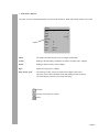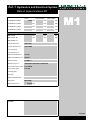
1
Operating Manual for Testing Machine BA ALPHA 3-3000 Deckblatt extern-e.ofm - 1.1 - 10/2004 DELTA 5-200 Basic informations 1 Setup and installation 2 Operating manual machine 3 Operating manual software 4 Operating manual Proteus 5 Test reports and certificates 7 Connection diagrams and spare parts lists 8 Conformity Certificate 9 10 Register-e.ofm - 1.0 - 05/2004 Operating manual strain transducers 6 Manufacturer's data Testing machine ALPHA 3-3000 Serial number 02643 Order number 07/1285 Year of construct. 2007 Manufacturer BA FORM+TEST Seidner+Co. GmbH Zwiefalter Str. 20 D-88499 Riedlingen Tel. +49 (0) 7371 9302-0 Fax +49 (0) 7371 9302-99 Internet: www.formtest.de eMail: [email protected] Copyright © by FORM+TEST Seidner+Co. GmbH Design and specifications subject to change without notice. The information of this product is published regardless of protection by a patent. The names of the goods are used without warranty regarding the free usability. We bestowed great care upon making up this manual; mistakes, however, cannot be excluded totally! The editor and writer cannot take any legal responsibility or undertake any liability for incorrect information and its consequences. We are always thankful for suggestions or references at mistakes! The manufacturer cannot take any legal responsibility or undertake any liability for accidents, injuries or their consequences which result from improper operation of the instruction model. This applies to the operators as well as to other persons. The operator has to take the respective safety precautions! Printed in Germany Maschinendaten-e.ofm - 1.0 - 03/2004 All rights reserved, even the rights for photomechanical reproduction and storing in electronic media. Manufacturer's data Testing machine DELTA 5-200 Serial number 41000 Order number 07/1285 Year of construct. 2007 Manufacturer BA FORM+TEST Seidner+Co. GmbH Zwiefalter Str. 20 D-88499 Riedlingen Tel. +49 (0) 7371 9302-0 Fax +49 (0) 7371 9302-99 Internet: www.formtest.de eMail: [email protected] Copyright © by FORM+TEST Seidner+Co. GmbH Design and specifications subject to change without notice. The information of this product is published regardless of protection by a patent. The names of the goods are used without warranty regarding the free usability. We bestowed great care upon making up this manual; mistakes, however, cannot be excluded totally! The editor and writer cannot take any legal responsibility or undertake any liability for incorrect information and its consequences. We are always thankful for suggestions or references at mistakes! The manufacturer cannot take any legal responsibility or undertake any liability for accidents, injuries or their consequences which result from improper operation of the instruction model. This applies to the operators as well as to other persons. The operator has to take the respective safety precautions! Printed in Germany Maschinendaten-e.ofm - 1.0 - 03/2004 All rights reserved, even the rights for photomechanical reproduction and storing in electronic media. Foreword This document facilitates to get to know your testing machine resp. your testing system (briefly called: machine) and its capabilities. The operating manual contains important information for a safe, proper and economical operation of the machine. The observance helps to avoid any risks, to reduce repair costs and downtimes and to increase the reliability and life expectancy of the machine. BA This operating manual must be permanently available at the site of operation. The operation manual has to be read and followed by any person who has to carry out works with/at this machine, e.g. • • • Operation, incl. preparation, trouble shooting in the operating cycle, waste disposal, etc. Maintenance (servicing, inspection, repair) and/or Transport Besides the operating manual and the currently valid safety regulations of the user’s country you have to observe the accepted technical rules for safe and professional working, too. The information of this product is published regardless of protection by a patent. The names of the goods are used without warranty regarding the free usability. We bestowed great care upon making up this manual; mistakes, however, cannot be excluded totally! The editor and writer cannot take any legal responsibility or undertake any liability for incorrect information and its consequences. We are always thankful for suggestions or references at mistakes! All rights reserved, even the rights for photomechanical reproduction and storing in electronic media. The manufacturer cannot take any legal responsibility or undertake any liability for accidents, injuries or their consequences which result from improper operation of theinstruction model. This applies to the operators as well as to other persons. © by FORM+TEST Prüfsysteme FORM+TEST Seidner + Co. GmbH Postfach 11 54 D-88491 Riedlingen Telefon: +49 (7371) 9302-0 Telefax: +49 (7371) 9302-99 Basisdokument-e.indd - 1.2 - 03/2006 The operator has to take the respective safety precautions! Designated Use The machine is designed for static loading with statical or dynamic course. It is designed for compression, bending or tensile tests. For a designated use of the machine the operating manual and the inspection and maintenance instructions have to be followed. The operating manual is a part of the machine and must therefore be permanently available at the site of operation. An extension of the field of application for the machine or its components results in a change of the designated use. The resulting additional risks have to be avoided by your adequate safety precautions. BA Duty to Exercise Diligence The machine has been constructed considering a danger analysis and after careful selection of the harmonized standards to be used and of further technical specifications. The machine corresponds to the safety requirements of the machinery directive of the E.C. and thus it corresponds to the state of the art. The used standards and directives are mentioned in the „Conformity Certificate“ or in the „Manufacturer’s Declaration”. The safety of the machine, however, can be put into practice only if all necessary measures are taken. So the user of the machine has the duty to plan these measures and to control their carrying out. The user of the machine must guarantee that • • • • • • • • • • • the machine is only used as directed only safe tests are performed the machine is operated only in perfect and working order protection devices are not manipulated or removed the functioning of safety devices (limit switch, proximity switch, emergency stop, etc.) is checked weekly the machine is immediately stopped in case of malfunction and that the defect is repaired without any delay the operating manual is permanently and completely available at the site of operation danger signs which are fixed on the machine are not removed and that they are kept legibly. only qualified and authorized staff operates, maintains and repairs the machine this staff is regularly instructed in industrial safety precautions and environmental care. Moreover the staff has to read the operating manual and has to respect the safety notes the staff wears appropriate safety clothes BA Operating Staff Please ensure that only qualified or trained staff operates the machine. These persons have to know the possible risks of the machine. You should clearly define the responsibility of your staff for • • • • the operation of the machine the preparation of the test the maintenance the repair. Works on electric components, e.g. during the installation, have to be done – in compliance with the electrotechnial rules - only by • • an electrician or trained persons under direction and supervision of an electrician. Works on hydraulic components should be done only by • persons with special knowledge and know-how in hydraulics. BA Working Place and Symbolism During the running the working place of the operating staff is in front of the machine. A working beside or behind the machine can be necessary for installation or maintenance purposes. The following danger signs can be attached to the machine and its accessories. Please note! Danger of injuring oneself! This component moves. Caution ! No automatic switch-off in case of contact! Danger of bruise ! This component can be closed mechanically, manually or automatically. Caution! No automatic switch-off in case of contact! Danger of burn or frostbite! These components can be or get very hot resp. cold! BA Signal Words in the Operating Manual In the operating manual we have marked the functions which may have any risk for the operator or the machine with the below mentioned signal words. Only skilled staff is allowed to carry out these functions carefully. DANGER Immediate threat, which can lead to serious injuries or death. WARNING Possibly dangerous situation which can lead to minor injuries . CAUTION Possibly dangerous situation which can damage the machine or an object in its direct surrounding. The most important aim of these safety signs is to avoid any bodily injury. Safety signs with the title „DANGER“ or „WARNING“ may contain risks for machines, accessories and the environment, too. BA Safety Precautions Before starting Before starting the machine please check and ensure that • • • only authorized staff is in the working range of the machine nobody can be injured by starting the machine all protection devices are available! Before the starting please also check if there are any damages/ defects at the machine. If so, please immediately inform your superior. During the operation Before the starting inform yourself about the correct behaviour in case of trouble. Emergency Stop In case of any danger you can immediately stop the testing machine by using the emergency stop (depending on the version of the machine either by pressing the read emergency stop push button or by turning the read emergency stop switch). Protective devices Please always use protection devices, especially when testing • specimens with high absorption of energy and deformation as springs, ropes, belts • specimens which splinter in case of break • with a high speed of piston or crosshead • by using of hardened or ceramic clamping jaws BA Safety Precautions Clamping tools hydraulic / pneumatic Do not put your hands between the clamping jaws! Please always use a pair of tongs for placing the specimens. Danger of injuring oneself! Never open clamping tools which are under pressure / tension! Danger of injuring and damage! Before opening the tools the clamped specimen has to be completely relieved of load. Never work on the test chamber when the machine is running. Danger of getting your fingers caught! Do never test specimens which are not correctly clamped or placed! Parts of the machine, e.g. the motor, can get very hot. In case of an existing tempering unit, even external parts can get very hot or very cold. Therefore touch these parts only by using protective gloves! In case of any installation or conversion works please proceed very carefully and prudently. Never put any objects in the test chamber or on the testing tools! The noise of the breaking specimen can cause hearing defects. Therefore use ear muffs! BA Safety Precautions Maintenance During the maintenance of the machine please observe the following points in order to avoid serious injuries or machine damages: • • • • Keep to the specified service and maintenance intervals! Observe the maintenance instructions! Do only use the indicated lubricants! Do only use spare parts in accordance to the enclosed spare parts list! Before maintenance or repair: • • • switch off the power switch in order to interrupt the power supply and secure it against unintentional reactivation by means of a padlock pull the mains plug or disconnect the mains connection wait until all parts of the machine which possibly have to be touched (e.g. the motor) have cooled down to room temperature! Before starting the machine after maintenance or repair works please check if: • • • • • all screwed connections have been screwed on again removed covers, strainers or filters have been installed again all materials and tools, which are required for maintenance or repair, have been removed from the working range of the machine possibly escaped liquids have been removed all protective devices of the machine are well-functioning. Only if all these works have been effected correctly and without any fault, the machine can be started again. If heavy machine parts have to be exchanged, only use suitable and perfect load carrying attachments and sling gears! BA Safety Precautions Works on the electrical equipment If an electrical connection is designated the testing machine or the control console has to be connected only by an authorized expert. Pay attention to the correct system voltage! Only skilled and qualified personnel are allowed to maintain or repair electrical equipment! • • • • • Check the electrical equipment regularly! Fix again loose connections ! Exchange damaged lines / cables without any delay! Keep the control cabinet always closed! Access is permitted only authorized persons with key / tools. Never steamclean control cabinets and other housings of electrical equipment (e.g. motors)! Never clean them by using a water hose! Works on hydraulic or pneumatic equipment Only persons with special know-how and knowledge of hydraulics are allowed to maintain or repair hydraulic or pneumatic equipment! • • • • • • • • Before maintenance or repair works the pneumatic and hydraulic equipment of the machine has to be made pressureless! Regularly check all lines, hoses and screwings concerning leakage or externally recognizable defects! Immediately repair any defects! Squirting-out oil can lead to injuries or fire! Hose lines should be exchanged regularly, after 6 years at the latest (resp. according to specifications of manufacturer), even if no damages are recognizable! Remove flown-out hydraulic oil at once! Slippery! Lay and mount hydraulic lines and compressed-air lines workmanlike. Pay attention to the correct connections! BA Instructions for Environmental Care The legal duties of waste avoidance, waste disposal and recycling have to be fulfilled while working on or with the machine! Especially while installation, repair or maintenance works water endangering materials like for example • • • • grease or lubricating oils hydraulic oils coolants cleaning agents containing solvents are not allowed to pollute the soil or to get to the sewage system! These materials have to be stored, transported, collected and disposed of in suitable containers! Exchange parts have to be disposed of in an environmentfriendly and safe way! If hydraulic oil has possibly escaped from the machine, please absolutely take care that it does not get to the soil or to the sewage system! BA Additional Information IMPORTANT It is important that the machine is installed in a room with a room temperature between + 16°C and +20°C in order to get exact test results. If the piston stroke is not sufficient, you can get the required test chamber height as follows: • • • Insert distance pieces, namely put them centrically on the lower pressure plate. Only distance pieces with a hardened and ground contact surface have to be used. If you have a testing machine with adjustable test chamber height, the upper pressure plate has to be brought to the specimen up to 10 mm. Put the specimen exactly centrically on the lower pressure plate or the distance piece. For this use the centering marks or a measuring tape. ATTENTION With all testing machines you have to pay attention to the piston stroke indicated in the technical data, i.e. after having reached the maximum piston stroke the machine is not allowed to be charged anymore! De-aeration of the pressure line If, contrary to all expectations, air has got in the line between pump and pressure cylinder (the piston extends jerkily), it can be removed as follows: • • • Carefully unscrew the swivel nut of the pressure line at the cylinder. Switch on the hydraulic power unit, set it at „pressure increase“ until oil comes out of the swivel nut. Then strongly tighten the swivel nut again. Check the oil-level and – if necessary – add oil. BA Maintenance Recommendation At delivery the oil tank is filled with the required hydraulic oil. We recommend an oil change every two years. The oil change has to be effected as follows: • • • See to it that the machine’s piston is in its final position. At the hydraulic power unit the oil drain plug is located at the lower edge of the oil tank. This drain plug has to be removed and the oil has to be collected in a suitable container. Then fix the oil drain plug again. Open the filling nozzle on the tank cover and fill in the new oil by using a funnel. Then close the filling nozzle. The oil level has to be checked monthly! Please only use blisterfree and acid-free hydraulic oil (see “our recommendation for lubricants” on the next page). Our machines are filled with: OEST / HLP 68. Every two weeks you have to do the following: • Visual control of the screw connections. If a screw has loosened please contact us concerning the tightening torque! BA Recommendation for Lubricants We recommend the use of the following lubricants: AGIP OSO 68 ARAL VITAMGF 68 VITAMDE 68 BP ENERGOL HLP 68 HLP 46S CHEVRON AW - HYDRAULIKOIL 68 MECHANISM LPS 68 ESSO NUTH H 68 UNIVIS N 68 MOBILOIL DTE 16 DTE 26 OEST HLP 68 SHELL TELLUS OEL 68 HYDROL DO 68 TEXACO RANDO OIL HDC - 68 RANDO OIL HCCZ - 68 BA Checkup and Acceptance of the Delivery The consignment has to be checked concerning external damages immediately on receipt. If the packing is in proper condition, you can accept the goods. Check the completeness of the consignment by means of the delivery note. IN If it is feared that a transport damage has happened, immediately make a record. The external damage has to be confirmed in writing by the carrier. The extent of damage should be described on the bill of lading or any other document as exactly as possible. In case of doubt do not accept the consignment. If a transport damage comes to light after the acceptance, the carrier has to be informed without any delay. A record should be made on the spot, either in the carrier’s or his representative’s presence. The record has to be signed by the carrier resp. his representative. Please do not make any modifications before the record has been made! Inbetriebnahme-e.indd - 1.0 - 04/2004 Then inform us about the extent of damage. This information must be as exact as possible. It has to enable us to judge if the damage can be repaired by sending spare parts, if a visit of our technician is necessary or if the machine has to be returned to our factory. Transport of the Machine For the transport of the machine only eye bolts type Starpoint VRS of the manufacturer RUD or equivalent products of other manufacturers should be used. • • • • • The delivered packing should be removed only at the place of installation The machine should be protected from any shocks No use of brute force Do not apply the lever to sensitive machine parts Consider the centre of gravity IN Installation of the Machine The machine has to be installed horizontally on a solid foundation and – if necessary - it has to be fixed by means of screws. After the installation the space between machine’s foot and floor has to be casted. If you have received a control console for the drive of the testing machine you have to make the connection between control console and machine by means of the delivered hydraulic hose (or line). It is important that the machine is installed in a room with a room temperature between + 16°C and +20°C in order to get exact test results. De-aeration of the pressure line If, contrary to all expectations, air has got in the line between pump and pressure cylinder (the piston extends jerkily), it can be removed as follows: • • • Carefully unscrew the swivel nut of the pressure line at the cylinder Switch on the hydraulic power unit, set it at “pressure increase” until oil comes out of the swivel nut. Then strongly tighten the swivel nut again. Check the oil-level and – if necessary – add oil. IN How to Rinse Out the Hydraulic System If the machine has been delivered with a separate hydraulic power unit, it is essential to rinse out the hydraulic system after the installation and before the commissioning. Normally this has to be done by one of our service technicians. If, however, you want to do it on your own, please absolutely contact our service department. IN Sense of the Pump Motor IN ACHTUNG • • • Auf Drehrichtung des Pumpenmotors achten! Motor muss in Pfeilrichtung drehen! Gegebenenfalls Drehrichtung des Motors durch Vertauschen von zwei Phasen ändern! ATTENTION • • • Please pay attention to the sense of the pump motor! The motor must rotate in direction of arrow! If this is not the case, please change the motor‘s sense of rotation by exchanging two phases! ATTENTION • • • Faites attention au sens de rotation du moteur de la pompe! Le moteur doit tourner en direction de la flèche! Si ce n‘est pas le cas, il faut changer le sens de rotation du moteur en échangeant deux phases! Abridged operation manual DigiMaxx C-20 n Switch on the machine by actuating the mains switch and then switch on the electronic unit by pressing button . Selection of the Machine n Select the desired machine by pressing button C20 MA Now – corresponding to the configuration of the digital display - M1 (up to M4) appears on the screen. n Switch over the hydraulic reversing valves to the respective machine. In case of machines with a solenoid switching valve the hydraulic and electronic unit are adjusted automatically. 0 Preparation of the Test n Press button . n By means of buttons menu Test Ramp. and you can select the sub- n Then press and select Ramp-Cycles. n By pressing the menu is opened. n Enter the following values: Cycles Stopping Vel Max Min 0 (no cycles) 0,0s desired load speed in kN/s nominal power of the machine 0,0 kN n The inputs must be confirmed by pressing n Then break off with the menu press and memorize with twice. . . For exiting Kurzbedienung DigiMaxx C-20-e.indd - 1.0 - 07/2006 n Now insert the specimen. Abridged operation manual DigiMaxx C-20 Execution of the Test n If necessary you can change the display N/mm² referred to the specimen’s area with button n Press START . The zero-adjustment is made automatically. The piston extends and the specimen is loaded with the preset value until it breaks. After the break the machine reduces the pressure automatically and the piston returns acc. to the preset sinking time (menu point “sinking time”) Now the machine is ready for another test.. START After pressing the display is automatically set to zero while the piston is extending. For this the machine needs about 2 seconds time. So please take care that the sinking time is set long enough so that at the next test after pressing START there are at least 2 seconds left until the piston contacts the specimen. End of the Test n Switch off the electronic unit by pressing and then switch off the machine by actuating the mains switch. . C20 DIGIMAXX C-20 Digital Control Unit 28.10.2002 as/la DIGIMaxx C-20 3000 kN F0 M1 0,00 kN 0,00 kN s + 7 4 DE Version 7 RES ZERO CALC DATA SET MA DI 5 22 1 FNC . PEAK 8 0 9 6 EX 3 ESC DEL Table of Contents • General view .....................................................................................3 • Explanations for the keys ..................................................................4 • Explanations for the display ..............................................................6 • Main menu ........................................................................................8 • Sub-menu "Print out".........................................................................9 • Print command of print-out..............................................................10 • Sub menu "Testing" ......................................................................... 11 • External test (Option) ......................................................................12 • Sub-menu "Ramp, Cycles"..............................................................13 • Ramp Programming for Cyclic Tests ...............................................14 • Automatic Test Course ....................................................................15 • Test course with measuring and weighing ......................................16 • Step Programming ..........................................................................17 • Programming of Elastic Modulus ....................................................18 • Calculation of Elastic Modulus ........................................................19 • Universal Programming (Option).....................................................20 • Adjustment (option) .........................................................................21 • Sub-menu "Settings" ........................................................................22 • Load Pacer......................................................................................23 • Zero Band .......................................................................................23 • Break detection ...............................................................................23 • Specimens' configuration /Specimens' memory...............................24 • Sub-menu "Factory Calibration" ......................................................26 • Linearization....................................................................................27 • Calibration Table .............................................................................28 • Calibration Values ...........................................................................29 • Manual Operation............................................................................30 • Sub-menu "LCD Contrast Setting" ..................................................31 • Sub-menu "Measuring/Weighing" (Option) .....................................32 • A4 - Page Printer.............................................................................33 Page 2 • General view Type of device: Real digital control unit which has been developped for all types of testing machines. Expandable to a fully automatic testing system in connection with balance, sliding caliper, measuring station and computer. Selection of the machines: The device is structurally divided in max. 4 machines. All settings can be made separately for each machine. Exceptions: specimens’ configuration and print-out inputs. Operation: At first select the respective machine.Then make all settings with the main menu. These settings are being preserved by a memory even after switching-off the device. For the securing of the machine’s functions "plant" and "calibration" are code-protected. Specimens’ configuration: The 30 most frequent types of specimens with dimensions and loading speed can be memorized under menu ‘’Specimens’ configuration’’. Test procedure: Select the desired specimen’s type with push-button CALC and start the machine. If a specimen is tested which has not yet been programmed you have to input the test course under menu ‘’ramp’’. During the test the screen indicates the load in kN. In case of respective measuring systems an additional displacement or deformation display is possible. Under ‘’test’’ free-programmable test courses are possible(only valid for C20). Computer interface By the serial interface of DIGIMAXX there is a full compatibility to the complete material testing software PROTEUS. Only some possibilities of this testing system are mentioned with the complete operation by computer and the graphical recording during the test. Memory (option) This memory allows a testing at the DIGIMAXX and then a subsequent transmission of the specimens’ data to the connected computer. Page 3 • Explanations for the keys Device on/off Peak value measurement on/off Peak value reset POWER PEAK RES Tare (zero setting / without memory) ZERO Selection of specimens with strength conversion free-programmable up to specimens 30 (ex works: cube 20 cm, cube 15 cm, prism 16 cm²) CALC Change-over of the display from N/mm² to kN when specimen is selected. Initialization of display FNC . Print command to computer or printer Storage of settings DATA Call main menu SET Start test - stop START Discharge specimen Stop - release sinking time / sinking without time limit STOP 5 Page 4 • Explanation for the Keys In case of double display Selection of measuring parameters with status line at the sueen. This applies to the change -over from ZERO to digit selection, etc., too. F0 = Force F0 DI = Displacement DI DE = Deformation EX = Extern Selection of machines (max. 4 machines) DE EX MA 7 9 1 3 0 Cursor (menu-control) 8 Cursor (menu-control) 2 Cursor (menu-control) 4 Cursor (menu-control) 6 Push-button Enter Paper feed printer / (option) Page 5 • Explanations for the LCD-display Selection of measuring parameters: Screen: Measuring range Actual machine (here machine 1) 3000 kN M1 3000,0 kN 0,00 kNs + Polarity of the actual value Display for unit of force Load pacer, indicates the measured load increase per unit of time Histogram 0-100% (not with double display) PK ZB RUN BD GD Control of status line. Here it is indicated if machine starts, charges, Status line for functionsstops, discharges, .... PK: peak active ZB: zero band active BD: break detection active BR: break detection released GD: detection of limiting value active MAX/MIN: Max/Min limiting value released Strength display: Programm no. (max. 30) Designation of specimen e.g. cube 150 mm Selection by push-button CALC 1 + W 15 M1 100,0 N/mm² 0,00 N/mm² s Strength display for selected specimen Load pacer PK FNC . ZB BD GD Change-over from strength display to force display without loss of values Page 6 • Explanations for the LCD-Display Double display: (Option) Control channel 3000 kN M1 Display for force resp. strength 3000,0 kN 0,00 kN s 100,00 mm + PK Force ZB BD DE Load pacer for force, displacement, deformation or extern Display for displacement, deformation or extern GD Selected 2. measuring parameter e.g. deformation Page 7 • Main Menu Main Menu M1 Report Test : Test Test parameter Specimen config Work Calib. LCD settings Save dec. point Reset Zero Vernier Balance Option ESC : Abort Move the beam 8 2 Selection Report: Setting of print-out data (date, number of specimen) corresponding to type of printer and mode. Test: Entry of a freely programmable test sequence according to the equipment of the machine. Test parameter: Inhibit resp. release and programming of machine settings and test settings corresponding to the selected options. Specimen config.: There are available up to 30 free-programmable (in dimensions and test speed) specimen types as for example cubes, cylinders and prisms. Work calibration: Provides menu items protected with a code for calibration and manufacturer's parametarisation of the system. Displays the software version. LCD settings: Contrast adjustment and switching off of the screen (standby). Save dec. point: Select the display parameter (FO force, DI displacement, DE deformation). With this menu you can store the places after the decimal point of the set parameter (FO,DI,DE). Reset Zero : Release of the tare, which has been effected with zerokey. Select the display parameter as described under “Save dec. point”. Vernier Balance: Switch on the sliding caliper and/or balance. Selection by MA. (Option) Page 8 • Sub-menu "Report" The print-out can be started manually or by the break detection. Date and testing number can be set. Report Option Ident Tester Order Age Quantity Day Month Year Enter : ESC : : : : : : : : : 1 0 0 0 0 0 0 Days 0 Read in Abort Ident: The testing number can be set up to 9 digits (continued) Tester: Setting of the laboratory assistant's or tester's number (max. 9 digits) Order: Setting of order number (max. 9 digits) Age: Specimen’s age (max. 9 digits) Day, month, year: The settings for day, month and year have 2 digits. After every input you have to press ENTER. (The date setting is neither stored nor automatically corrected. It must be set daily) ESC DEL Escape DATA Printing of the print-out screen Enter Page 9 • Print command of print-out The print-out is automatically started by the break detection. By pressing the DATA key the print-out can be started manually. Then according to the configuration (sliding caliper, balance) the displayed measuring value, the specimen’s number, the type (in case of N/mm² only) and the date are printed. In case of connected sliding caliper and/or balance the following print-out is made: Example 1. Example 2: (measuring + weighing) Example 3: (with option E-Software) Example 4: (with option E-software measuring + weighing) Force average Quantity Break3 Break2 Break1 Age Speed. No. Date Bulk dens.aver.2837 kg/m3 Force aver. +35.7 N/mm2 Quantity 3 Strength3 + 35.5 N/mm2 Bulk density 2881 kg/m3 Weight 9620 g Height 149.0 mm Width 149.5 mm Length 149.8 mm Strength2 + 35.2 N/mm2 Bulk density 2807 kg/m3 Weight 9536 g Height 150.5 mm Width 150.2 mm Length 150.2 mm Strength1 + 36.4 N/mm2 Bulk density 2823 kg/m3 Weight 9498 g Height 149.9 mm Width 149.8 mm Length 149.8 mm Age 28 Speed + 0.05 N/mm2/s Specimen W150 No. 1 Date 17.03.95 + 572.2 kN 3 + 564.5 kN + 586.1 kN + 566.0 kN 28 + 11.25 kN/s 3 17.03.95 By pressing the ENTER key the paper feed is started. Page 10 • Sub-menu "testing" Different test courses are possible: A simple ramp function with cycles, a step program and a program for the E-Module test according to standard. A free-programmable universal test with smooth change-over is possible as an option. Operation 1. Main Menu M1 Report Test : Test Test parameter Specimen config Indication of the test type: ramp, steps, E-module or universal selection by key ENTER By selection of the menu "testing" the following programming - and selection menu appears: 2. Test M1 Programming of the test Test parameter Test, Cycles Univers Steps E-Modul Selection of the test type under menu "settings" selection by key ENTER By selection of the menu "setting" the following selection screen appears: 3. 300 kN Test : Peak : M1 Test ON selection of the test type. Page 11 • External test (Option) Funktion: ® By pressing START the piston extends, the specimen is being charged and the preselected control-parameter is switched on. By pressing STOP the specimen is being discharged again. Application: ® Calibration of displacement-, deformation- and external channel. ® Tests with external control point and internal control-parameterconnection. Test Procedure: 1.Calibration of displacement transducers: ® In the menu “adjustment” set the preload to %. ® In the menu “test” select “external”. With key MA select the control parameter and memorize with ESC/DATA. ® In the menu “test” select “settings”. Select “external” with key MA and memorize with ESC/DATA. ® Press START. ® On treshold the selected control parameter is smoothly adjusted. ® Calibrate the transducers by means of the handwheel or the keys ↑↓. ® Discharge the machine by pressing STOP. ® Restore the treshold. 2. Test with external control point: ® In the menu “test” select “external”. With key MA select the control parameter and memorize with ESC/DATA. ® Select “settings” in the menu “test”. Select “external” with key MA and memorize with ESC/DATA. ® Reset the external control point to 0.000 V. ® Press START. ® On treshold the selected control parameter is smoothly adjusted. ® Run the test with the external control point. ® Discharge the machine by pressing STOP. Page 12 • Sub-menu "Ramp, Cycles" 3000 kN Test Cycles: Hold: Vel: Max: Min: M1 0 .00s 01 kN/s 3000.000 kN .000 kN MA : Choice ESC : Abort step on The mode “adjustment” allows by means of deformation method a clamping of the tension specimen or the manual extension of the piston to a bending specimen (option). The selection of the control parameter makes force-, displacement-, deformation and external controlled tests possible. The piston is always extended in such a way that the specimen is touched by the platen (frictional connection), except in case of “adjustment” mode (option for double display). The cycle input permits repetitions. In case of abortion the last cycle number is indicated. If you input cycle 0 it means that the machine is run to the max. force up to its standstill. The holding time permits the holding of the maximal and minimal load. The vel.-input is equivalent to the load increase per unit of time. The machine is only charged to the minimal value when the number of cycles is higher or equal to 1. If you select displacement, deformation or external as a control parameter, the load is replaced by the respective parameter (option). Page 13 • Ramp Programming for Cyclic Tests Entrance from main menu (ramp). Here cyclic test can be programmed, but only for testing in kN (not in N/mm²) • number of cycles determines how often the specimen is charged/discharged. With 0 the machine is run up to the set maximal force. The force stops at this point. With STOP you can discharge again. • holding time determines how long the machine stays on the max. and min. loading points. • vel. determines how fast the specimen is charged resp. discharged • max. value determines the upper limit of the ramp • min. value determines the lower limit of the ramp F holding time r holding time max. value discharge min. value charge Start holding time cycle 1 cycle 2 w F t max. force r Remains if cycle = 0 Start wt Page 14 • Automatic Test Course Settings before the test in case of display in N/mm² Break detection BD must be activated. The selection of the specimen must be already made, e.g.: 200,0 (cube with edge length 200 mm) CALC 160 (cylinder with Ø 160 mm) Course of the Test START key Extension of piston: Charging: Sinking: The peak is automatically activated and is restored together with the break detection. The force is zeroized and the frictional connection is detected. The specimen is charged up to its break with a programmed speed. The break detection has come into action: - the printer prints out (option) - the piston sinks - the sinking time runs down (can be prematurely stopped with STOP). - the piston stops -2 x STOP: the proton returns completely to its initial position. Additional Test Courses Change-over of parameters (option) Setting operation (option) - e.g. the specimen is set displacement-controlled, the test is made force- or displacement-controlled Page 15 • Test course with measuring and weighing 1. Select the specimen type with CALC. 2. Start the test by pressing START, the measuring screen is invoked. 3. Input the dimensions or measure them. 4. By means of the key START return to the test screen and carry out the test. 5. Combined with a printer a print-out is effected automatically after rupture if the break detection is activated. 6. Without measuring/weighing of the specimen the measuring invocation can be omitted by key EX. Key FNC In case of selected specimen type you can - after the test -switch over from N/mm² to kN by pressing key FNC. The correct display of the load pacer is important, as the specimen is charged according to this: N/mm² FNC . kN N/mm²/s FNC . kN/s In case of specimens with selected conversion factor the breaking load is indicated furtheron with 100%. Without Selection of Specimen Measuring and weighing is inhibited. Page 16 • Step programming With thies step program max. 10 programmable steps with common speed and holding time can be run up and down. if it should run further on the programmed steps only after the manual START, you have to set a holding time of "0 seconds" (no holding time). Ramp and holding time can be stopped with START at any time. Steps Vel: 20.000 kN/s 1 : 300.000 kN 2 : 300.000 kN 3 : 300.000 kN 4 : 300.000 kN 5 : 300.000 kN 6 : 300.000 kN 7 : 300.000 kN 8 : 300.000 kN 9 : 300.000 kN 10: 300.000 kN Hold : 99999 s ESC : Abort M1 Force control and force display Max. 10 steps Velocity range of a 3000 kN machine: 0,001 ...3000 kN/s Holding time in seconds max. 99999 s Setting: 0 s = automatic holding and extension with START Setting is done by means of a numerical keyboard and the key Page 17 • Programming of Elastic Modulus With this program the programming of test course for the determination of the elastic modulus conforming to standards DIN 1048 and EN 196 is possible. In this test program the control system is always force-controlled. E-Modul Measurem: Spec: Durchm: Meas.Leng: Cycles: Hold: Vel: Max : Min : MA type of measurement displacement, deformation, extension) type of speciment (prism, cylinder, cube or beam) length of edge or diameter measuring length at the specimen number of cycles holding time of the last ramp test speed max. force min. force CYLINDER 160.0mm 100mm 3 30.00s 10.050kN/s 500.000kN 10.050kN : Choice Test Scheme: Force F r calculated load ramp holding time unload load end of cycle holding time Start Cycle 1 Cycle 2 Cycle 3 0 w Time t manual stop zeroization of the displacement measurement with key "zero" Page 18 • Calculation of Elastic Modulus After the execution of the ramp which is determining the elastic modulus the value of the elastic modulus is printed out by a connected printer Example: ELASTIC MODULUS CUBE EXTENSION 1 LOAD 1 EXTENSION 2 LOAD 2 MEAS. LENGTH AGE TESTER ORDER IDENT DATE 32250 N/mm 150,0 mm 0,001 mm 0,5 N/mm 0,101 mm 22,0 N/mm 150 mm 30 Tage 5 98123 1 23:01:98 and, at the same time, is shown at the test screen: E-Modul 32250 M1 0,0 kN 00,0 kN 0,000 kN ZB DE Calculation Formula for the Elastic Modulus ∆F ∆D ∗ Lo fp ∆F = force difference ∆D = deformation difference Lo = measuring length fp = specimen's area of cross section Page 19 • Universal Programming (Option) SoftwareModule U - Smooth Commutation of Control Parameters Functional Description The smooth commutation between the control parameters „force“, „displacement“, „extension“ and „extern“ makes possible the execution of demanding tests of building material or metallic material. The test procedure is programmed in three ramps which are freely definable in control parameter, load speed, ramp value and holding time. During the test the commutation is effected automatically or prematurely by pressing the key. The smooth commutation is also possible in PC-operation. Operation Main Menu M1 Indication of the test type Report Test : Univers Test parameter Specimen config Test M1 Programming of the test Test parameter Test, Cycles Univers Steps E-Modul 200 kN Test FO DE DI 10.000 kN 0.200 kN/s 5.00 s 0,500 mm 0,005 mm/s 0,00 s 5.000 mm 0,020 mm/s 1,00 s Selection of the test type under menu "settings" M1 Programming example for a universal test with three ramps, force-,extension-,and displacement control Page 20 • Adjustment (Option) After having pressed the key START the hydraulic cylinder can be run or stopped in any position by means of the arrow keys or the connected handwheel. This is necessary if you want to clamp e.g. a specimen for tensile test. Operation: Main Menu M1 Report Test : Test Test parameter Specimen config Test Call up menu "test" M1 Activation of the adjustment mode in menu "settings" Test parameter Test, Cycles Univers Steps E-Modul Set up Perepare: Test: Peak: Auto Test: Auto Start: Reli: Vel: MA : Choice ESC : Abort M1 ON Univers ON OFF OFF .001mm/s .001mm/s Adjustment: ON/OFF Test: inthe adjustment mode only universal test is possible Peak: peak value memory ON/OFF Auto course: ON/OFF Auto Start: ON/OFF Discharge: Discharging speed of the piston Start: Starting speed of the piston Page 21 • Sub-menu Settings Set up M1 Sink time: Time: Auto Zero: Disp.measur: Pacemaker: Zeroband: Break detec: Level: MA ESC • ON 3.0s ON ACT FO ON OFF 20.0% : Choice : Abort step on Sinking Time The sinking time permits a controlled return of the machine's piston after the break, i.e. after this time the piston is stopped. The sinking time is activated by the specimen's break or by the stop key. With stop the sinking time can be aborted. After this time it can be activated by stop once again, that's why the piston is sinked completely. • Automatic Zeroizing 1-2 seconds after starting the display is automatically set to zero.His important that there is not yet a frictional connection, as otherwise the breaking load won't be correct. For this zeroizing the machine needs approx. 2 seconds. So please take care that the sinking time is respectively set, so that with the next test after the start signal there are at least 2 seconds left for the piston's extension to the specimen. Displacement Measuring: (Option) AKT: travelling displacement display, which always measures and indicates the actual displacement. HLD: displacement display is stopped at force maximum, i. e. it is only measured in case of increasing force. PEAK-measurement must be on. Peak value Force Displacement Hold MAX: displacement display is stopped at maximum value, i.e. the maximal displacement is measured and indicated. PEAK-measurement must be on. • Load pacer In case of double display the load pacer can be firmly adjusted to force: FO or selection ANW. In case of selection: ANW the parameters FO,DI,DE and EX can be freely selected. • Zero Band If the zeroband is activated changes around the zero point which are smaller than 0,1% referred to the final value (option) are suppressed. For calibration the zeroband can be switched off. • Break Detection The break detection must be switched off in case of tests which are displacemenresp. deformation-controlled or tests during which the ramp is run downwards and in case of calibration. The treshold in %0 of the machine range corresponds to the force drop, which is necessary to release the break detection. After starting the display switches from BD to BR. If a printer is connected a test printout (certificate) is printed automatically. The break detection is reset with RES. * Function: Break detection due to force decrease. When a specimen breaks the force decreases. If the level is exceeded, the break is detected. This level can be set between 1 and 100 %0. The default value is 50 %0. If e.g. hard specimens should not be destructed too strongly, the level must be set lower. For further information please see “sub-menu settings”. • Limiting Values (Option): * FIX Max. limit at 103% or at the end of the converter range. MAX display. RES key for deleting. * 2SP 2 limiting values MIN and MAX, programmable or at the beginning or the end of the converter range. MIN./MAX. display. RES key for deleting. Can be switched on and off separately. * 2NS 2 limiting values MIN and MAX, programmable or at the beginning or the end of the converter range. MIN./MAX. display. Deleted when sinking below the programmed hysteresis point by 2%. Can be switched on and off separately. As a safety, the limiting values also react at - 4,6% (MIN) and + 104,6% (MAX) of the uncalibrated measuring range. This corresponds to absolute zero resp. the end of the A/D converter range. This case occurs if or tare point + MIN.-limiting value calibration point + MAX.-limiting value exceed the converter range. The maximum and minimum limiting values can be set for the protection of the machine or of the specimen. In the customer's configuration the maximum and minimum limiting value can be separately switched on and off and the levels can be programmed as well. Programmable limiting values (2SP, 2NS) can be set in digits in the range of -3% up to 103%. Switch on with MA. Page 23 • Specimens' configuration / Specimens' memory Spec. M1 Specimen configuration Read memory Clear memory Free %100 ESC: Abort - Speciment configuration: Open this menu window by pressing key ENTER and subsequent input of an access code. Code: The code is given along with the operating manual. Spec. 1 * Cube Convert Width : 100.0% : 200,0 mm : Spec. +/MA : Choice SET : Input ESC : Abort Up to 30 specimens are freely configurable. Specimens 1 to 3 are configured by the factory. Select the specimens to be configured (max. 30) 8 MA 2 Select the type of specimen ( cube, prism, cylinder,rod, plate) 0 SET 5 After pressing SET the numeric keys are active. Press the ENTER key when the measure input is completed. Page 24 Conversion input: conversion factor in order to display and print out e.g. the strength with 95%. As soon as another value than 100% is set for the conversion it is displayed by a "*" in front of the specimen type. Measure input: cube: max. 999 mm side length (edge) prism: max. 99999 mm² face cylinder: max. 999 mm diameter plate: max. 999 mm length, max. 999 mm width The following inputs are possible: cube stone prism 3-point beam 3-point pressure prism beam pressure prism 4-point beam 4-point plate off cylinder rod rod - Read Storage: By pressing the key ENTER the output of the stored data to a PC which is connected by the COM-interface is effected. For each specimen the settings for the print-out, the type of specimen, the measuring results and the calculated strength are stored and output. The data are only stored by the manual pressing of the key DATA at the end of the test or automatically after the the detection of the specimen’s break (when “break detection” is activated – option) The data of the specimen can be transferred to the PC by a serial COM-interface and can be stored at the same time. - Delete Storage: All stored specimen data are deleted by pressing the key ENTER. The storage is reset to the initial value. After having read the data the storage should be deleted so that the system is ready for the next tests. - Free % 100: Indication of the free storage in %. 100% - the storage is empty 0% - the storage is full, no more data can be stored. Page 25 • Sub - menu "Calibration" Select sub-menu: factory calibration Set cursor to calibration Press ENTER Set the calibration code XXXX CAL. FUNCTIONS M1 Machine Calibration Delete calib. Linearisation calib. table Delete table Print cal. table Calibr. values Control calibrat 1-2 ESC : Abort Select the machine. Set cursor to the required line. Press ENTER to reach the desired machine. • Calibration Layout Delete the table (in case of first calibration only). ZERO Reset the display to zero (first calibration: zero reset with trimmer Z) The calibration is executed at 80% of the measuring range. 1. START 2. • Run selected calibration value manually according to the calibration instrument asdescribed under point "Manual operation". The display can deviate from the screen. The machine discharges. The calibration value is newly calculated. First calibration: Run calibration value according to display. Set calibration value with trimmer G at the calibration instrument. Delete cal The saved calibration is deleted. Page 26 • Linearisation The precision of the testing machine can be increased by means of linearisation. If the table is empty, all points have to be run. This is not necessary if you want to correct individual points´. Procedure: START The piston is extended. (force free) 0% calibration value is read in. The display is set to zero,calibration value to 2%. Now, as described under point "Manual operation" run to 2% of the max. force. 2% calibration value is read in and is increased to 4%. Run machine up to 4% according to the calibration instrument. 4% calibration is read in and increased to 6%. Apply same procedure for 10, 20, 40, 60, 80, 100% as in step 2 for 4%. At the first recording of the linearization values, all points have to be run. If a wrong measuring value is read in, press DI or DE to switch to the old position. Press ENTER again when the correct calibration value appears. After the last input (100%) the message “table completed” appears. DI DE 9 select the next higher calibration value. 1 select the next lower calibration value. ESC DEL DATA ESC DEL ESC DEL Abortion with storage of the linearisation value Abortion without storage ! Attention: if the linearisation is executed it is not allowed to calibrate anymore! Page 27 • Calibration Table The calibration table contains the values measured during calibration/linearization. Individual values can be corrected by input. ! Attention: If there is no print-out it is advisable to note down the table for the present. Select the correction line with the ENTER key. Overwrite the line directly with the new value. ! Attention: The keyboard is directly in the number mode. If there is an input in the wrong place then the relevant calibration value is lost. But if the calibration table is left by ESC the modifications are not valid. To get back to the old values, the instrument has to be switched off and on again. Calibration Table Before Calibration/Linearization M1 (Enter, ESC) 0% 2% 4% 6% 10 % 20 % 40 % 60 % 80 % 100 % TAR.Val. Cal.Fact ESC • : 27675 39675 51675 63675 87675 147675 267675 387675 507675 627675 27675 30000 Abort Delete the Table By pressing ENTER the values, which have been read in during the calibration / linearization, are deleted and the table is reset in its starting position. ! Attention: if no print-out has been made, it is adrisable to note down the table! • Print-out the Table By pressing ENTER the calibration table is printed if a printes is available. Page 28 • Calibration Values To check the calibration of a machine a calibration series has to be run. Calibration values: Input of max. 10 loading steps and one speed holding time. The inputs can be stored. Auto Calib. Vel M1 30.00 kN/s 300.000 kN 600.000 kN 900.000 kN 1.200.000 kN 1.500.000 kN 1.800.000 kN 2.100.000 kN 2.400.000 kN 2.700.000 kN 3.000.000 kN 10 s 1 2 3 4 5 6 7 8 9 10 Hold : ESC : Abort The calibration series can be automatically run at first upwards and then downwards. After expiry of the holding time or by renewed pressing of START the next value is run. 3000 kN M1 45,5 kN + START : N-STEP STOP : DISCHARGE PK off ESC : Abort After pressing the START key the first calibration step is run. (The zero adjustment is effected automatically.) Page 29 • Manual Operation Application Manual charging with partial or full load, for example for calibration or linearization. Procedure START Start the test. START By pressing START once more the control unit switches from CHARGE to MANUAL STOP and stops the ramp. 8 2 SET 5 MANUAL UP 1..4 Slow run up with step 1. By pressing the key again you can raise the step. MANUAL DOWN 1...4 Reduction of step UP to step DOWN by repeatedly pressing this key. Slow run down to step 1. By repeatedly pressing the key you can raise the step DOWN. Reduction of step DOWN by ↑. MANUAL STOP With this key you can stop at any time. Setting of the steps: Step 1: 0,01 % Step 2: 0,25 % Step 3: 1,0 % Step 4: 5 % of the max. force Page 30 • Sub - menu LCD Contrast Setting LCD : : contrast M1 LCD brighter LCD darker Value : 3 Enter : Standby ESC : Abort Selection through main menu By means of ↑ and ↓ the contrast of the LCD-display can be adjusted in 8 steps for the compensation of strong temperature fluctuations. 8 lighter 2 darker By pressing ENTER the display is switched to the standby - function. By pressing any key it is switched back to the operation mode. Page 31 • Sub-menu „Measuring / Weighing“ (Option) Starting from the main menu by means of the key ENTER at „measuring / weighing“. Set up Vernier Inp. Balance Inp. Height measur Cube : Plate: M1 ON MET ON 150,0 mm 35,0 mm MA : Choice ESC : Abort The three inputs for measuring, weighing and height measuring of the specimen can be switched on and off separately, if these connections are installed and released in the works configuration. MA 0 commutation ON/OFF In the beginning of the test the specimen’s dimensions are selected by means of key CALC. With key START you can switch over to the measuring screen. Dimensions Lenght : Width: Height: Weight: Bulk density: 150,0 mm 150,0 mm 150,0 mm 7520 g 2228kg/ m 3 Start : Furtheron ESC : Abort Length: Input by means of a connected sliding caliper or by means of the keyboards and key ENTER. Width: Input by means of a connected sliding caliper or by means of the keyboards and key ENTER. Height: Input by means of a connected sliding caliper or by means of the keyboards and key ENTER. In case of configuration of a height measuring i.e. displacement measuring system at the test cylinder, this fade-in does not appear. Weight: Input by means of a connected balance or by means of the keyboards and key ENTER. START Starting of the test cylinder Page 32 • A-4-Page printer With the operation of an A4-page printer the title „TEST RECORD“ is printed and the line counter is reset after pressing the key ENTER. Release of the print-out with key DATA or after release of the break detection. The printer is to be connected to the serial interface RS 232 at the DigiMaxx. • Handwheel (Option) The operation of a machine with a handwheel enables you to position the hydraulic cylinder of a machine very accurately. After pressing START the control system goes to Manual-Stop and now - by turning the handwheel to the left or to the right - the hydraulic cylinder can be run up- or downwards. By switching over the flip switch the piston’s speed can be increased or decreased. Page 33 Installation of the software Proteus Proteus is a 32 bit application and can therefore be installed on the following operating systems: • Microsoft Windows NT 4.0 with Service-Pack 3 or higher • Microsoft Windows 2000 • Microsoft Windows XP Attention: Windows 95/98/ME are not allowed anymore, also not for the updates. Microsoft Windows Vista is not released at the moment. Important when the installation is under Windows NT, 2000 or XP: In order to install the software the user must have administrator rights. IP Procedure: • Place the CD-ROM into your CD-ROM drive. • In the event the installation doesn’t start automatically, click on the Start button on your windows task bar then on Run. Type in the drive letter of the CD-ROM drive followed by “:setup.exe” and click on OK. • With the choice of the language you decide in which language the screen prompts are given during the installation of the software. The actual language the program operates in can be changed at any time with in Proteus. • Follow the remainder of the on screen instructions • Once the programme is installed it can be started by double clicking the Proteus icon on your desktop. Additional notes: After a new installation: • After installation you must load the experiment modules from the CD-ROM this is done by clicking on the Menu Configuration, and clicking Experiment module. • Now you are able by clicking on the Menu Configuration and picking tuner amplifiers, gauges to configure the whole system including servo(s), machine(s), channels and gauge(s) such as Vernier calipers, scales, measuring station etc... After installing an update: • A new version can always be installed over an existing one. However, it is recommended to first make a backup copy of the Data and Gendata folders, or to copy the complete Proteus folder into a temporary folder. • All configurations and settings, particularly formulas, test scripts etc... remain unchanged. • Warning: Problems can occur due to the rounding of the values of certain parameters such as weight, density, BW factor etc in existing test templates. In the event of a problem please check the values on the problematic test template. Please also consult the chapter regarding computer system requirements (in the Proteus Manuel). Configuration of a testing machine on site, with a customer supplied personal computer (i.e. no PC is delivered) You will find the completely manual of the software on the enclosed CD. Installation Proteus-e.indd - 1.5 - 03/2007 • The configuration is stored in the folder “Gendata” and all the tests are stored in the folder “Data” on the enclosed Manual-CD (not Proteus-CD). • After the installation of Proteus both folders “Data” and “Gendata” (with the path Program Files/Proteus) have to be overwritten by the folders saved on the supplied CD. • Now the software is correctly configured and the tests, which were made in the factory, can be shown and – if necessary - repeated for demonstration or teaching purpose. OPERATING MANUAL Electronic Double and Triple Strain Transducers LD DD1-2-3 Version 2 17.09.2002 as/la Electronic Double and Triple Strain Transducers Type LD-DD1-2-3 for measuring the mean longitudinal deformation at two/three generating lines at concrete cylinders, prisms, cubes or drilling cores. It is very suitable for the determination of the modulus of elasticity (E-modulus) according to DIN 1048, EN 196, etc. Consisting of: • • Electronic double strain transducer type BD 25/50-DD1 Electronic triple strain transducer type BD 25/50-DD1 Technical data: Transducer type: Transducer bridge: Bridge resistance: Measuring distance: Accuracy class: Supply voltage: Allowed ambient temperature: HBM-DD1 full bridge 350 Ω +/- 2mm (2mV/V) 0,1% of the nominal range 10 V DC -10 … +60°C • 4 sets of connecting rods for the following measuring lengths: 40-80, 60-120, 100-170, 150-220 mm, optional: 200-320 mm • Clamping for prisms and cylinders: Ø 30…80 mm, 70…160 mm Optional: 150 … 250 mm • • Weight: Including: 450 g Aluminium box Measuring cable, 3 m with connection cable for mean value circuit 2 Knurled Screw (1) Connecting rods (2) Knurled Screw (3) Double/Triple strain Transducer at concrete cube Dimensions (in mm) type table locking leverl (4) scale 1:1 calibration level positive indication pict. 2: measuring electronics negative indication measuring edge (5) 3 knurled screw (1) connecting rods (2) pict. 3: Triple Stain Transducer at concrete cylinder Triple Strain Transducer Double Strain Transducer pict. 4: Double and Triple Strain Transducer with accssories 4 Functional Description: Double Strain Transducer LD-DD1-2 Triple Strain Transducer LD-DD1-3 1. Prepare the strain transducer by attaching the connecting rods corresponding to the specimen to be tested. 2. The dimensions of the specimen (length of face resp. diameter) can be adjusted by means of the scale at the connecting rods. Do the same with the measuring length LO. 3. Now the strain transducer is clamped at the specimen. The design of the strain transducer makes it possible to clamp it at a specimen which is already placed in the testing machine and to remove it again. 4. When the strain transducer is exactly adjusted, the locking levers are slewed out so that the measuring edges get free. 5. Zeroize the electronic system and charge the specimen corresponding to the respective standard. 6. To avoid any damages, the specimen must not be charged until it breaks if the strain transducer is clamped at. Standard Test for the Determination of the E-Modulus according to DIN 1048 and EN 196 According to DIN 1046 ten load cycles have to precede the measuring cycle which determines the E-modulus. According to EN 196 1..3 load cycles have to precede the measuring cycle which determines the E-modulus. • • • The lower test voltage is specified as 0,5 N/mm² The upper test voltage is specified being approx. 30% of the expected breaking load. The loading speed should be 0,5 N/mm²/s. The following values are necessary for the determination of the compressionE-modulus: = force difference in N=.. = area under pressure in mm² = strain difference in mm = L… = measuring length mm These data must be inserted in the following formula: ED = … 5 Example for the Calculation of the Compression-E-Modulus Given: specimen (lxwxh) area under pressure (A) measuring length (L0) 40x40x160 mm 1600 mm² 100 mm Force min. (F1) Force max. (F2) = 30% of the expected breaking load 0,5 � 800 N 25,5 � 40800 N This results in: ∆ F � 40000 kN Extension (L ) on F Extension (L ) on F 0,002 mm 0,145 mm This results in: ∆ L � 0,143 mm This example results in the following E-modulus: ED = ∆ F x L0 ∆LxA 40000 N x 100 mm 0,143 mm x 1600 mm² = 17482,5 N/mm² or ED = 17482,5 MPa 6 A1.1 Basic Data Distributor Customer Servi Motion Order no. 07/1285 Year of construction 2007 Machine M1 ALPHA 3-3000 Machine M2 DELTA 5-200 B1 Machine M3 Machine M4 Drive AS-C20-N Colour RAL 7032 RAL 3002 Note: Inspected by Daniel Nacke Date 10.04.2007 07/1285 Maschinenprüfbericht-e.ofm - 1.3 - 05/2005 Unassigned data fields are irrelevant for your machine configuration. The respective options are not included in the scope of supply or rather in the present equipment . A1.2 Machine Record Card Machine M1 Type of machine ALPHA 3-3000 Machine no. 02643 Max. test force 3.000 kN B2 Strain test Accuracy class class 1 Cylinder no. 07034 Width Depth Dimensions framework Dimensions hydraulics Dimensions of bore holes machine base Dimensions of bore holes drive Weight framework Height 750 650 1.750 mm 650 1.100 2.100 mm 680 380 mm 380 650 mm Weight hydraulics 1.800 kg 280 kg Remarks Machine M2 Type of machine DELTA 5-200 Machine no. 41000 Max. test force 200 kN Strain test Accuracy class class 1 Cylinder no. 06121 Width Dimensions framework Dimensions hydraulics Dimensions of bore holes machine base Dimensions of bore holes drive Weight framework Depth 1.450 Height 850 2.350 mm mm 1.270 500 mm mm 1.700 kg Weight hydraulics kg Remarks 07/1285 A2 Hydraulics and Electrical System Supply voltage 3 x 400 V + N + PE 50 Hz Control automatic Control cabinet 600/800/2000 Electronic system DigiMaxx C20 Measuring amplifier below 2M 2A HE Measuring amplifier above Hydraulic pump RZ 1,4/2-9/B30-Z 1,5 Pump motor 90 L 4-1,5 kW Oil cooler CP-STD-224 Oil filter HP31.10VG.HR.E.P.G.3.-.AOR Filter cartridge 300065 Main stop valve Flow control valve Hydraulic hose 2X S16 500 long 1X S20 400 long Hydraulic connections at the control cabinet Servo valve 1X S20 , 1X S12 , 2XS16 Solenoid valve 2X G 3-2 , 1X G 3-3 Back pressure valve ÜK-18-20 Oil type HLP 68 HVM 025-003-1200-4G Oil quantity 68 dB (A) Sound pressure level Motor protection switch Motor protection switch relay pre-set Software 1 33 litres 3,60 Ampère Proteus Version Software 2 Version Software 3 Version 7.4.0 PC Monitor Electrical plan no. 300 E 3031-1 Hydraulic plan no. 300 H 1040 Remarks 07/1285 A2.1 Hydraulics and Electrical System Data of sensors/valves M1 Force Piston stroke Deformation 1. Measuring range 3.000 kN mm mm 2. Measuring range kN mm mm 3. Measuring range kN mm mm 4. Measuring range kN mm mm Manometer kN kN kN Manometer-Ø mm mm mm M1 Manometer no. Pressure transducer P8AP-500 Pressure transducer no. 103410258 Force transducer Force transducer no. Displacement transducer TS 100 Displacement transducer no. 023235 Extension sensor LD-DD1-3 Extension sensor no. 105030032/105030031/105030018 Piston stroke position switch LS-11/XLA Door position switch LS-11/P Reversing valve Stop valve Manometer throttle valve Safety valve Safety valve pre-set MV 42 BR 410,00 bar Remarks 07/1285 A2.2 Hydraulics and Electrical System Data of sensors/valves M2 Force Piston stroke Deformation 1. Measuring range 200 kN mm mm 2. Measuring range kN mm mm 3. Measuring range kN mm mm 4. Measuring range kN mm mm Manometer kN kN kN Manometer-Ø mm mm mm M2 Manometer no. Pressure transducer Pressure transducer no. Force transducer CTC4-200 KN Force transducer no. 402795 Displacement transducer TLH 225 Displacement transducer no. 025309 Extension sensor 2X displacement tracer WA/50 mm Extension sensor no. displacement tracer No. 110710151/110710157 Piston stroke position switch Door position switch (2X) LS-11/XLA Reversing valve Stop valve Manometer throttle valve Safety valve Safety valve pre-set MV 42 CR 220,00 bar Remarks 07/1285 A3.1 Framework M1 Pressure Piston area M2 3000 200 754,38 103,81 M3 M4 kN cm² Piston ring area cm² Compression 397,48 192,55 bar Piston stroke 100,00 220,00 mm Dimensions of test chamber 340,00 220,00 mm M1 M2 Pressure plates above Hardness Depth of roughness Pressure plates below Hardness Depth of roughness M3 M4 320X520X75 230X40 mm 57,50 58,80 HRC 0,55 0,81 µm 320X520X75 230X40 mm 57,30 58,10 HRC 0,59 0,60 µm M1 M2 M3 M4 Adapter Ø180X180 Distance plates Ø x thickness mm Distance plates Ø x thickness mm Distance plates Ø x thickness mm Distance plates Ø x thickness mm Distance plates Ø x thickness mm M1 Distance pieces Hardness Depth of roughness Distance pieces Hardness Depth of roughness Distance pieces Hardness Depth of roughness MR1 M2 M3 M4 210X210X110 mm 56,30 HRC 0,75 µm 170x170x50 mm 55,40 HRC 0,82 µm 120x120x50 mm 53,80 HRC 0,73 µm Distance pieces mm Hardness HRC Depth of roughness µm Remarks 07/1285 A3.2 Framework M1 M2 M3 M4 Grooved ring Wiper ring O-Ring 310x6 O-Ring MR2 24X3 (2X)105X5 O-Ring O-Ring O-Ring Stepseal S90X105,1X6,3 T46N RSSO Piston sealing O-Ring 105X5 Piston guide Teflon 9,5X2,5 Rod guide Teflon 9,5X2,5 Bellows FB 04 001 4 M1 Diameter of bending rolls Length of bending rolls Distance of bending rolls Accessories M2 M3 M4 40,00 20,00 mm 610,00 210,00 mm 1.020,00 300,00 mm - see work card - M3 = 4 point load 07/1285 A4 Calibration table Indicator no. 07020 Machine M1 M2 Measuring range 1 1 0% base table KT base table 2% 4% 6% 10 % 20 % 40 % 60 % 80 % 100 % Tare value Calibration factor Value 0 mV/V - 17,3 kN - 1,4 kN Value 1 mV/V + 1873,3 kN + 97,83 kN Value 0 mV/V kN kN Value 1 mV/V kN kN Machine Measuring range 0% 2% 4% 6% 10 % 20 % 40 % 60 % 80 % 100 % Tare value Calibration factor Remarks 07/1285 A5.1 Factory configuration electronics Electronic system DigiMaxx C20 EPROM version DMAX V9.60 SUCY WE1 Machine configuration M1 ON M2 ON M3 OFF FO CH1 CH2 FO 3000 200 FO kN kN DI CH5 CH5 DI 100 220 DI mm mm DE CH6 CH6 DE 2 2 DE mm mm EX OFF CH7 EX 50 EX mm M4 OFF Machine set M1 M2 2,0 1,0 s 0 0 ‰ Load 0,5 0,5 % Start 8,0 7,0 V Step 0 0 Number 0 0 Relieve -10,0 -10,0 V B-susp. 2 2 s P-Reset ON ON Stop OFF OFF Gain:5,0 Gain:3,0 PI-susp. Break test Threshold M3 M4 Remarks 07/1285 A5.2 Factory configuration electronics Gain set M1 M2 M4 M3 C20 C22 FO FO 15,0 4,0 0% 0% 8,0 8,0 2% 2% 6,0 6,0 4% 4% 5,0 5,0 6% 10 % 4,0 4,0 10 % 30 % 3,0 3,0 30 % 60 % 2,0 2,0 60 % 80 % 1,0 1,0 80 % 95 % 1,0 1,0 DI DI 150,0 50,0 DE DE 20,0 20,0 EX EX 1,0 50,0 F.DI F.DI 5 5 F.DE F.DE 2 2 F.EX F.EX 1 3 WE2 Relays MIN OFF MAX R2 BREAK OFF M2 R3 M3 OFF M4 OFF I-MIN DOOR: OFF I-MAX RESERV: OFF Options Ext. change-over ON OFF 10V output Break detection ON OFF Printer RSR Keyboard MNU Limit values OFF Pacemaker Language ON OFF ENG Plug COM2 ON OFF Limit value factor 20 Adjust ON Strength N/MM² Servo CS6 Ext. Soll PC control ON OFF Memory MIN Peak ON OFF DATA Output Remarks ON ON OFF OFF OFF OFF ON OFF Print Way: OFF Stop+Print : OFF Pump On/OFF : OFF 07/1285 KL- FB 07 Test Certificate Customer : Servi Motion Order number/DKD-number: 07/1285 Machine:Typ/Force/No./Year: ALPHA 3-3000 , 200kN , M.Nr.02643 , 2007 No. of: Display/Trancducer: C20/07020 , TC4200kN/402795 Calibrationtemperature: 20,0 °C (Room) Hardness of pressure plate : 57,5 HRC (Top) 57,3 HRC (down) Flatness plates (Top): O.K Roughness of pressure plate : 0,55 µm (Top) 0,59 µm (down) Flatness plates (down): O.K Measure devices Manufactor Typ 20,5 °C (Cal ibration Loadcell) Serialnumber Calibrationcertificate valid Compression Loadcell : HBM C18 00282L3N BAM-S1 E1661 Sep.2007 Measureamplifier : Hottinger DK 38 S6 S32 20320005 17871 DKD-K-00101 06-09 Nov.2008 Location of machine: Factory (complete Adress): Date of test/ Tester : 19.03.07 Nacke Notes : Step [kN] Set value [mV] 2 Value 1 [mV] Value 2 [mV] Value 3 [mV] Average [mV] Reversibility [mV] Relative Relative Rel. stdRel. Rel. error of repea- deviat. display accuracy reversibil tability [type A] resolut. q[%] ity v [%] b[%] A[%] a[%] 0,01333 0,01335 0,01335 0,01335 0,01335 0,01344 -0,12 0,67 0,00 0,00 0,50 5 0,03334 0,03335 0,03335 0,03337 0,03336 0,03355 -0,06 0,54 0,06 0,02 0,20 10 0,06667 0,06666 0,06665 0,06667 0,06666 0,06698 0,02 0,47 0,03 0,01 0,10 20 0,13335 0,13328 0,13328 0,13330 0,13329 0,13381 0,04 0,38 0,02 0,01 0,05 40 0,26670 0,26653 0,26651 0,26654 0,26653 0,26738 0,06 0,32 0,01 0,00 0,03 60 0,40005 0,39980 0,39963 0,39979 0,39974 0,40090 0,08 0,28 0,04 0,01 0,02 80 0,53341 0,53313 0,53311 0,53311 0,53312 0,53433 0,05 0,23 0,00 0,00 0,01 120 0,80011 0,79987 0,79984 0,79986 0,79986 0,80097 0,03 0,14 0,00 0,00 0,01 160 1,06679 1,06672 1,06668 1,06668 1,06669 1,06735 0,01 0,06 0,00 0,00 0,01 200 1,33343 1,33360 1,33353 1,33355 1,33356 0,01 0,00 0,01 -0,01 This document is not valid any longer after Residual display Fio [kN] fo [%] Value 1 Value 2 Value 3 0,0000 0,0000 -0,0100 0 0 -0,01 Acceptable maximum value in % Relative error of accuracy "q" : Relative error of reversibility "v" : Relative error of repeatability "b" : Relative zero error "fo" Relative resolution "a" Place: Riedlingen Class 0,5 ± 0,5 ±0,75 0,5 ±0,05 0,25 Class1 ± 1,0 ±1,5 1,0 ± 0,1 0,5 Date: 19.03.2007 transport or relocation of machine Class2 ± 2,0 ±3,0 2,0 ± 0,2 1 Class3 ± 3,0 ±4,5 3,0 ± 0,3 1,5 Signature: Nacke KL- FB 07 Test Certificate Customer : Servi Motion Order number/DKD-number: 07/1285 Machine:Typ/Force/No./Year: ALPHA 3-3000 , 3000kN , M.Nr.02643 , 2007 No. of: Display/Trancducer: C20/07020 , P8AP500bar/103410258 Calibrationtemperature: 20,0 °C (Room) Hardness of pressure plate : 57,5 HRC (Top) 57,3 HRC (down) Flatness plates (Top): O.K Roughness of pressure plate : 0,55 µm (Top) 0,59 µm (down) Flatness plates (down): O.K Measure devices Manufactor Typ 20,5 °C (Cal ibration Loadcell) Serialnumber Calibrationcertificate valid Compression Loadcell : HBM KD 3000 4x600 205/4049 BAM-S1 E1642B Aug.2007 Measureamplifier : Hottinger DK 38 S6 S32 20320005 17871 DKD-K-00101 06-09 Nov.2008 Location of machine: Factory (complete Adress): Date of test/ Tester : 19.03.07 Nacke Notes : Step [kN] Set value [mV] Value 1 [mV] Value 2 [mV] Value 3 [mV] Average [mV] Reversibility [mV] Relative Relative Rel. stdRel. Rel. error of repea- deviat. display accuracy reversibil tability [type A] resolut. q[%] ity v [%] b[%] A[%] a[%] 60 0,04712 0,04736 0,04735 0,04732 0,04734 0,04753 -0,46 0,44 0,08 0,03 0,17 150 0,11779 0,11837 0,11841 0,11842 0,11840 0,11818 -0,51 -0,20 0,04 0,01 0,07 300 0,23552 0,23691 0,23701 0,23707 0,23700 0,23598 -0,62 -0,46 0,07 0,02 0,03 0,47076 0,47221 0,47207 0,47205 0,47211 0,47091 -0,29 -0,24 0,03 0,01 0,02 600 900 0,70574 0,70652 0,70662 0,70650 0,70655 0,70589 -0,11 -0,09 0,02 0,01 0,01 1200 0,94044 0,94111 0,94117 0,94106 0,94111 0,94067 -0,07 -0,04 0,01 0,00 0,01 1800 1,40902 1,40996 1,41013 1,41008 1,41006 1,40981 -0,07 -0,02 0,01 0,00 0,01 2400 1,87648 1,87791 1,87809 1,87806 1,87802 1,87856 -0,08 0,03 0,01 0,00 0,00 2,34283 2,34479 2,34502 2,34497 2,34493 0,01 0,00 0,00 3000 -0,09 This document is not valid any longer after Residual display Fio [kN] fo [%] Value 1 Value 2 Value 3 0,3000 0,1000 -0,2000 0,01 0 -0,01 Acceptable maximum value in % Relative error of accuracy "q" : Relative error of reversibility "v" : Relative error of repeatability "b" : Relative zero error "fo" Relative resolution "a" Place: Riedlingen Class 0,5 ± 0,5 ±0,75 0,5 ±0,05 0,25 Class1 ± 1,0 ±1,5 1,0 ± 0,1 0,5 Date: 19.03.2007 transport or relocation of machine Class2 ± 2,0 ±3,0 2,0 ± 0,2 1 Class3 ± 3,0 ±4,5 3,0 ± 0,3 1,5 Signature: Nacke Page 1/2 Test acc. to DIN 51302 part 2 Costumer : Order No.: Machine (Typ/Force/No./Year): No. of Display/Trancducer: Calibration temperature: Hardness of pressure plate: Roughness of pressure plate: Flatness of pressure plate: Druckkraftaufnehmer : Digitalkompensator : Diameter of force transmitting area: Measuring range: Tester: Date of test: Remarks: Servi Motion 07/1285 ALPHA 3-3000 , 3000kN , M.Nr.02643 , 2007 C20/07020 , P8AP500bar/103410258 20,0 C° (Raum) 20,5 °C (Calibration Loadcell) 57,5 HRC (top) 57,3 HRC (down) 0,55 µm (top) 0,59 µm (down) O.K top O.K down Hottinger KD 2000 4x600 Werk-Nr. 89 Hottinger DK 38 S6 S32 Werk-Nr. 20320005 100 mm 2000 kN Nacke 19.03.2007 1. Test result: Self alignment of the upper pressure plate Rn % 10 20 40 80 100 M1 0,00 0,01 0,01 0,01 0,01 M2 0,02 0,01 0,00 0,00 -0,01 M3 -0,02 -0,02 -0,02 -0,02 -0,02 M4 0,00 0,01 0,01 0,02 0,02 allowed +/- 0,10 +/- 0,10 +/- 0,10 +/- 0,10 +/- 0,10 2. Test result: Alignment of the component parts of the machine ∆R n % 10 20 40 80 100 M1 0,05 0,02 0,01 0,01 0,01 M2 0,05 0,02 0,01 0,01 0,01 M3 0,03 0,03 0,02 0,01 0,01 M4 0,03 0,03 0,02 0,01 0,01 3. Test result: Restraint on tilt of the upper pressure plate % 10 20 40 80 100 Wv,h 0,041 0,033 0,027 0,024 0,023 Wl,r -0,041 -0,033 -0,026 -0,023 -0,022 allowed 0,060 0,050 0,050 0,040 0,040 allowed 0,10 0,10 0,10 0,10 0,10 Page 2/2 Costumer : Order No.: Machine: Servi Motion Servi Motion 07/1285 ALPHA 3-3000 , 3000kN , M.Nr.02643 , 2007 Measuring values Serial 1 1 1 1 1 2 2 2 2 2 3 3 3 3 3 4 4 4 4 4 5 5 5 5 5 6 6 6 6 6 7 7 7 7 7 8 8 8 8 8 Place: % M1 (front) M2 (back) M3 (right) 0,16449 0,15388 10 0,1547 0,32192 0,30839 20 0,31483 0,63423 0,61567 40 0,62972 1,25491 1,22812 80 1,26022 1,57361 1,56535 1,53373 100 0,15755 0,15701 10 0,16246 0,31534 0,31137 20 0,32246 0,62686 0,61891 40 0,63782 1,24594 1,23146 80 1,26973 1,58412 1,55537 1,53744 100 0,16208 0,15255 10 0,1592 0,32008 0,30627 20 0,3178 0,63249 0,61276 40 0,63288 1,25347 1,22365 80 1,26328 1,57736 1,56332 1,52899 100 0,1595 0,15692 10 0,15933 0,3149 0,31348 20 0,32126 0,62647 0,6219 40 0,63661 1,24495 1,23654 80 1,2686 1,58247 1,55458 1,54338 100 0,20405 0,15528 10 0,11671 20 0,24911 0,38771 0,31042 40 0,51977 0,74335 0,62017 80 1,06546 1,44711 1,24019 1,33714 1,79816 1,54987 100 10 0,19341 0,12652 0,15547 20 0,37212 0,26364 0,30922 40 0,72208 0,54024 0,61636 80 1,42451 1,08742 1,23159 1,77515 1,3594 1,53931 100 10 0,1575 0,16194 0,11527 20 0,31598 0,31995 0,24797 40 0,62901 0,63296 0,52148 80 1,25339 1,25751 1,06787 1,56337 1,56895 1,34251 100 10 0,15602 0,16388 0,19362 20 0,31241 0,32401 0,37159 40 0,62316 0,64007 0,72063 80 1,24518 1,26794 1,41592 1,55497 1,57978 1,76036 100 Riedlingen M4 (left) 0,1594 0,31894 0,63739 1,27811 1,59806 0,15766 0,31689 0,63518 1,27602 1,59566 0,16233 0,32241 0,642 1,28472 1,60526 0,15571 0,3133 0,63041 1,26871 1,58711 0,15872 0,31671 0,63196 1,26365 1,57851 Serial 1: Pressure plate tilted to frontside Serial 2: Pressure plate tilted to backside Serial 3: Pressure plate tilted to the right Serial 4: Pressure plate tilted to the left Serial 5: Loadcell moved to frontside 0,15776 0,317 0,63493 1,27161 1,58861 Serial 6: Loadcell moved to backside 0,19905 0,3791 0,73032 1,43472 1,78343 Serial 7: Loadcell moved to the right 0,12077 0,25603 0,53215 1,08885 1,36809 Serial 8: Loadcell moved to the left Date: 19.03.2007 Signature: Nacke E HEM Prüfprotokoll test certificate/ orotocoled'essai Tvp: DD1 Auftrag: type/ type 801082906 orderno / commission Nennmessbereich: 2,5mm Prüfer range/ portöe / contröleur examiner ldentNr: 10503001 8 BäT Datum: serialno/ N'- ident 15.02.07 test date/ date d'essai Prüfergebnisse: testresults/ rösultats d'essai Eingangsgröße desMessbereichs [%] Ausgangsgröße [mVA/] inputquantity / 6chelle d'essai outputquantity/ r6suliats positiveAnzeige negativeAnzeige negativeindication/ indicationnegative positiveindication/ indicationpositive -0.0001 -1.2475 -2.4971 -1.2479 0.0001 0 50 100 50 0 0.0001 1.2529 2.5044 1.2529 0.0002 : Aus den Prüfergebnissen Eigenschaften berechnete und sonstigemesstechnische metrological characteristics calculated fromthemeasunng resultsandothers valeurscaracteristiques calcul6es ä partirdesrösultats d'essa -2.4970 2.5043 Kennlinienabweich nkteinstel ung, Anfangspu lung [%vC] 0.03 0.02 Relative Umkehrspanne [%vC] 0.02 0.00 KennwertC [mVMl sensitivity/ sensibilite combinederrori eneur combin6e relativehysteresis/ hysteresisrelatif AllgemeineZusatzinformationen : general information/ informationscomplömentaires Alle weiteren messtechnischen Eigenschaften des Aufnehmers sind durch Typprüfungen und laufende Produktaudits des Qualitätswesens abgesichert. All other metrologi€l characteristicsof the transducerare verifiedby type testingand regularproductauditsof the qualitydepartment. Toutes les autres caracteristiquestechniquesdu capteur sont garantiespar le SeruiceQualit6,au moyen d'essais et d'audits suivissur le produit. Zertifiziert nach ISO 9001 und 15014001 (DQS40001) ISO 9001 and ISO 14001 certitled / Certificationselon ISO 9001 et ISO 14001 Akkreditiertes DKD Kalibrierlaboratorium und EMV-Prüflaboratorium AccreditedDKD calibrationlaboratoryand EMC testing laboratory Laboratoireaccr6dit6Darle DKD et laboratoired'essais CEM DKD-K-00101 : DAT-P-006/12 qaHyllMes:!ee!{r"9n9[_**lB].i919j:}.:"9f,fJ, |reltifser _**j1?9:P"?r**!_ A u s g a b e1 6 6 1 4 v e r s i o n a 1 2 . 0 4 . 2 0 0M 5 oor *_***. _ ,,,,,,,,,,,,,,,, ,_1 1 5 . 0 0 - 1,4 1,,,," 3PP m HEM Prüfprotokoll test certificate/ protocoled'essai Tvp: DD1 Auftrag: type/ type 801084520 order no / commission Nennmessbereich: 2,5mm Prüfer rangei portöe BäT examiner / contröleur 105030031 ldentNr: Datum: 23.02.07 testdate/ dated'essai serialno / No-ident Prüfergebnisse: testresults/ r6sultats d'essai Eingangsgröße desMessbereichs [%] Ausgangsgröße [mVA/] inputquantity/ 6chelled'essai outputquantity / resultats negativeAnzeige positiveAnzeige negativeindication/ indicationnegative positiveindication/ indicationpositive 0 50 100 50 0 0.0004 -1.2489 -2.4996 -1.2487 0.0004 o.0oo4 1.2514 2.5008 1.2514 -0.0001 Aus den Prüfergebnissen berechneteund sonstigemesstechnische : Eigenschaften metrological characteristics calculated fromthe measuring resultsandothers valeurscarac{6ristioues calcul6es ä Dartirdesr6sultatsd'essai KennwertC [mVA{ -2.4999 2.5004 0.02 0.02 -0.01 -0.02 sensitivity/ sensibilit6 Kennlin ienabweichu ng,Anfangspunkteinstellung [%vC] combinederror/ erreurcombin6e Relative Umkehrspanne [%vC] relativehysteresis / hystör6sis relatif AllgemeineZusatzinformationen : general information/ informationscompl6mentaires Alleweiteren messtechnischen Eigenschaften abgesichert. desAufnehmers sinddurchTypprüfungen undlaufende Produktaudits desQualitätswesens All other metrologicalcharacteristicsof the transducerare verifiedby type testing and regularproductaudits of the qualitydepartment. Toutes les autres caracteristiquestechniquesdu capteur sont garantiespar le ServiceQualitö,au moyen d'essais et d'audits suivis sur le produit. Zeftifizieft nach ISO 9001 und 15014001 (DQS-00001) ISO 9001 and ISO '14001certified / Certificationselon ISO 9001 et ISO 14001 Akkreditiertes DKD Kalibrierlaboratorium und EMV-Prüflaboratorium AccreditedDKD calibrationlaboratoryand EMC testing laboratory Laboratoireaccredit6oar Ie DKD et laboratoired'essais CEM DKD-K-001 2 01: DAT-P-006/1 letq$e,Eldyin*lpe,.J9elr**qrylFr lq Tel:I:.,p,*e****9j_2*qa.',s*gk"_,,,,,,,,,, . -_ **"_ __-,,, _,*-. 1'15.00-1413PP Ausgabe 166'f 4version a 12.04.2005 Moor E HEM Prüfprotokoll test certificate/ orotocoled'essai Typ: Auftrag: DD1 type/ type 801084520 orderno/ commission Nennmessbereich: 2.5mm Bär Prüfer range/ portee examiner / contröleur ldentNr: 105030032 Datum: 23.02.07 testdate/ dated'essai serialno / No-ident Prüfergebnisse: testresults/ r6sultats d'essai Ausgangsgröße [mVA/] Eingangsgröße des Messbereichs [%] outputquantity/ rösultats inputquantity/ öchelled'essai negativeAnzeige positiveAnzeige negativeindication/ indicationn6gative positiveindication/ indicationpositive 0 50 100 50 0.0002 -1.2487 -2.4980 -1.2485 0.0003 n 0.0003 1.2515 2.5023 1.2514 0.0000 Aus den Prüfergebnissen berechnete Eigenschaften : und sonstigemesstechnische metrological characteristics fromthe measuring calculated resultsandothers valeurscaract6ristiques calculees ä partirdesresultats d'essai KennwertC [mVMl -2.4982 2.5020 0.01 0.01 -0.01 -0.01 sensitivity/ sensibilit6 Kennlinienabweichung, Anfangspunkteinstellung [%vC] combined error/ erreurcombin6e Relative Umkehrspanne [%vC] relativehysteresis/ hysteresisrelatif AllgemeineZusatzinformationen : general information/ informationscompl6mentaires Alle weiteren messtechnischen Eigenschaften des Aufnehmers sind durch Typprüfungen und laufende Produktaudits des Qualitätswesens abgesichert. All other metrologicalcharacteristicsof the transducerare verifiedby type testing and regular productaudits of the qualitydepartment. Toutes les autres caracteristiquestechniquesdu capteur sont garantiespar le SeruiceQualit6,au moyen d'essais et d'audits suivis sur le produit. Zeftifizieft nach ISO 9001 und 1S014001 (DOS-00001) ISO 9001 and ISO 14001certified / Certiflcationselon ISO 9001 et ISO 14001 Akkreditiertes DKD Kalibrierlaboratorium und EMV-Prüflaboratorium AccreditedDKD calibrationlaboratoryand EMC testinglaboratory Laboratoireaccreditepar le DKD et laboratoired'essais CEM DKD-K-0O1 01: DAT-P-006/1 2 lqiilspl,.?:l*yil.U:::*fljt,I_9r!H * "*- -..-_* _ , * , ,_"tf,,"r_i:rel,9::-19."*Pf1?::P?!rre!e91,.,*****- A u s g a b e1 6 6 1 4 v e r s i o n a 1 2 . 0 4 . 2 0 0M 5 oor 115.00-1413PP 1 2 3 4 5 6 7 8 Türe gebrückt Pumpe 1 27.03.2006 Zoll Datum 11.02.2004 Bearb. Zoll 2 C-20, 2 Maschinen, m. Pumpe Ein/Aus, Magnet, Schlüsselschalter Deckblatt Allgemein Gepr. Zustand Änderung 1 Datum Name Norm 2 Ers. für Urspr. 3 Ers. durch 4 5 6 Anlage: A1 Ort SCH E-3\300E3031-1 7 Blatt-Nr. 1 Bl von Anz 1/4 8 1 2 3 4 5 6 7 8 L1 L2 L3 N 1 3 5 -F1 10A 13 -Q2 2 4 6 /3.2 14 I> I> I> -T1 L1 -R1 L1 1 2 3 1 -Q1 4 5 3 5 -K1 -K1 /3.2 /3.2 6 2 4 N -G1 13 6 + - 14 -F2 4A -X1 -X1 L1 L2 L3 N PE -X1 U V W PE -X1 PE 1U N 1 2 0V PE 24V+ -B1 U V W PE M 11.02.2004 Zoll Änderung 1 Datum Name Norm 2 Ers. für Urspr. 3 Ers. durch 4 Steuerstromkreis 24 V DC Öl-Kühlermotor (Option) C-20, 2 Maschinen, m. Pumpe Ein/Aus, Magnet, Schlüsselschalter Leistungsteil Allgemein Gepr. Zustand Stromversorgung Elektronik -M2 Pumpenmotor Datum Bearb. -X1 1 -M1 Entstört mit Murr RC 3R Zoll L1 PE N M 3 21.03.2006 Steuerstromkreis geerdet N PE P PE 5 6 Anlage: A1 Ort SCH E-3\300E3031-1 7 Blatt-Nr. 2 Bl von Anz 2/4 8 /3.1 /3.1 /2.8 2 3 4 5 6 7 8 -X1 1 24V+ 24V+ 1-24V+ 3 Digimaxx C 20 13 Digimaxx C 20 Control 1 -Q2 -X10 3 -X1 12 5 grün -S1 -X1 -X1 8 11 8 10 15 -X1 -X1 9 ADC 2 -X11 3 -X10 11 braun 11 -X10 /4.1 weiß -X10 14 gelb /2.2 -X11 /4.1 10 -X1 13 -X1 15 16 63 -S2 -K1 12 -X1 2 64 7 13 53 -S3 13 -K1 2 14 54 7 13 Türe M1 11 -S4 -K3 -S6 14 14 12 -X1 -X1 6 13 11 /4.4 21 14 14 11 -S7 -S5 -K3 12 22 14 -X1 7 13 Türe M2 -X1 -K4 12 X1 A1 -K1 A2 A2 X2 A2 -X1 0V 4 21.03.2006 Zoll 1 2 3 4 5 6 13 14 53 54 63 64 Datum 11.02.2004 Bearb. Zoll Start-Stop /2.2 /2.2 /2.2 /2.6 13 14 21 22 33 34 43 44 3 5 /4.1 Umschaltung M1/M2 C-20, 2 Maschinen, m. Pumpe Ein/Aus, Magnet, Schlüsselschalter Steuerungsteil Allgemein Gepr. Zustand Änderung 1 Datum Name Norm 2 Ers. für Urspr. 3 Ers. durch 4 Kolbenhubendsch. Pumpe ein ( Optional ) Not- Aus Türendschalter 0V A1 -K3 ( Optional) /2.8 A1 -K2 -H1 5 6 13 14 21 22 31 32 43 44 4 4 /4.2 /4.3 Anlage: A1 Ort SCH E-3\300E3031-1 7 Blatt-Nr. 3 Bl von Anz 3/4 8 /4.1 1 /3.8 /3.8 2 3 4 7 8 24V+ 1-24V+ 13 /3.4 31 43 -K3 /3.7 32 -X1 44 14 -X1 17 18 1 -X2 19 1 -Y1 13 -S8 -K3 /3.7 14 -X1 20 1 -Y2 2 X1 A1 -Y3 2 -K4 2 -H2 A2 X2 0V Zoll Datum 11.02.2004 Bearb. Zoll 13 14 21 22 33 34 43 44 Türe gebrückt Schlüsselschalter Türe Maschine 2 Druckloser Umlauf Maschine 1 0V 21.03.2006 /3.6 C-20, 2 Maschinen, m. Pumpe Ein/Aus, Magnet, Schlüsselschalter Steuerungsteil Allgemein Gepr. Zustand 6 24V+ 1-24V+ -K2 /3.8 5 Änderung 1 Datum Name Norm 2 Ers. für Urspr. 3 Ers. durch 4 5 6 Anlage: A1 Ort SCH E-3\300E3031-1 7 Blatt-Nr. 4 Bl von Anz 4/4 8 1 2 3 4 5 6 7 8 Option Option Option A1 A2 -4 -2 Y2 -3 Y3 a r p a r p -11 R -5 -15 P -14 -6 -9 -12 R1 -13 -10 C M -7 L R b p a t M p G3-2 r -8 Y1 a -1 17.02.2004 Zoll P Datum 10.11.2000 Bearb. Stöhr G epr. Zus tand Änderung 1 Datum Name Norm 2 Urspr. Ers . für 3 Ort Hydraulikschema Ers. durch 4 Anlage: 2 Maschinen, Magnetumsch., Gegendruck Allgemein 5 H-3\300H1040 6 7 A1 Schalts chrank Blatt-Nr . 1 Bl von Anz 1/1 8 Konformitätsbescheinigung/Conformity certificate The conformity certificate for your test-machine will be sent to you in a separate E-Mail. BA Zusatzblatt Konformitätsbescheinigung.indd - 1.0 - 04/2005 Die Konformitätsbescheinigung zu Ihrer Prüfmaschine wird Ihnen in einer separaten E-Mail zugesandt.