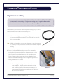
1
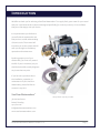
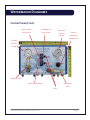
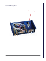
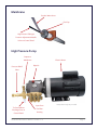
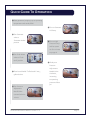
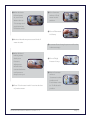
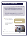
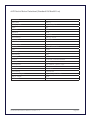
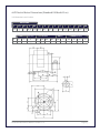
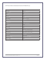
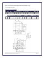
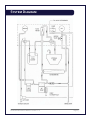
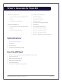
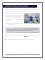
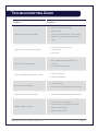
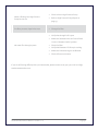
Watermaker Manual
For Electric / Generator-Driven Models G-20 & G-40
Installation, Operation and Maintenance
401.400.2226 | [email protected]
36 Harrison Street, Bristol, RI 02809 | www.seaclearwatermakers.com
Version 1.1-G
TABLE OF CONTENTS
Introduction ................................................................................................................... Page 3
Watermaker Diagrams ....................................................................................................Page 4
Operating Manual ........................................................................................................... Page 7
Quick Guide To Operation..........................................................................Page 8
Starting Your Watermaker ....................................................................... Page 10
Shutting Down Your Watermaker............................................................. Page 13
Long Term Storage ................................................................................. Page 14
Maintenance Manual ..................................................................................................... Page 16
Pre-filters............................................................................................... Page 17
High Pressure Pump ............................................................................... Page 17
Installation Manual ....................................................................................................... Page 22
System Diagram..................................................................................... Page 23
What’s Included In Your Kit ...................................................................... Page 24
Control Panel Installation........................................................................ Page 25
Pre-filter Installation .............................................................................. Page 26
High Pressure Pump Installation .............................................................. Page 27
Membrane Installation ............................................................................ Page 29
Seawater Lift Pump Installation .............................................................. Page 29
Running Tubing and Hoses ...................................................................... Page 30
Initial System Start-up ............................................................................ Page 33
Appendices
............................................................................................................. Page 35
High Pressure Pump Repair ..................................................................... Page 36
Troubleshooting Guide............................................................................ Page 37
INTRODUCTION
We’d like to thank you for selecting a Sea Clear Watermaker™ to supply fresh, pure water for your vessel
and your crew. Because this system was designed specifically for cruisers by cruisers, we’re confident
that you will be happy with your choice.
It’s important that you familiarize
yourself with the watermaker and
that you have a solid understanding
of how it works. This manual will
introduce you to the system and will
walk you through its installation,
operation and maintenance.
By taking proper care of your
watermaker, you’ll not only extend
the life of your investment, but you
should also be able to easily diagnose
any issues that may arise.
If you have any questions about
the installation, operation or
maintenance of your Sea Clear
Watermaker, please feel free to
contact us any time.
Sea Clear Watermakers™
* Pump shown is for G-40 model.
36 Harrison Street
Bristol, RI 02809
401.400.2226
[email protected]
www.seaclearwatermakers.com
Sea Clear Watermakers™ Manual - Version 1.1-G
Page 3
WATERMAKER DIAGRAMS
Control Panel (Front)
High Pressure
Sea Water Lift
Membrane
Pump Switch
Pump Switch
Pressure
Pressure
Gauge
Adjustment
Needle Valve
Pre-filter
Pressure
Gauge
Sea Water Valve
Product Water Gauge
Fresh Water
Valve
Fuses
Sea Clear Watermakers™ Manual - Version 1.1-G
Page 4
Control Panel (Back)
Pre-filter Pressure Gauge
Sea Clear Watermakers™ Manual - Version 1.1-G
Page 5
Membrane
Product Water Hose
End Cap
High Pressure Tubing to
Pressure Adjustment Needle
Valve on Control Panel
High Pressure Pump
Output to
Membrane
Pressure Relief
Electric Motor
Dipstick
Valve
To Second Brine
Discharge Port on
Control Panel
Input from
* Pump shown is for G-40 model.
Pre-filter
Housing
Sea Clear Watermakers™ Manual - Version 1.1-G
Page 6
OPERATING MANUAL
Quick Guide to Operation ........................................Page 8
Starting Your Watermaker ..................................... Page 10
Shutting Down Your Watermaker ........................... Page 13
Long Term Storage (more than 5-7 days without use) ............... Page 14
Sea Clear Watermakers™ Manual - Version 1.1-G
Page 7
QUICK GUIDE TO OPERATION
❶ Start generator, bringing it up to operating
temperature and steady RPM
❻ Turn on Seawater
Lift Pump
❷ Turn Seawater
valve to
“Seawater intake”
position
❼ Turn on High
Pressure Pump
and let system
run for 1 minute
to purge air
❸ Turn Fresh Water
valve to “Flush
tank” position
❽ Slowly turn
Pressure
Adjustment
❹ Place hose labeled “To flush tank” into 5
gallon bucket
Needle Valve
clockwise,
increasing
to operating
pressure of 800
❺ Turn Pressure
psi
Adjustment
Needle Valve
counterclockwise
2 times
Sea Clear Watermakers™ Manual - Version 1.1-G
Page 8
❾ When bucket is
⓭ Turn Seawater
full and water
valve to “Flush
ok, turn Fresh
water intake”
Water valve to
position
“To storage tank”
positionand set
full bucket aside
⓮ Turn off Seawater
Lift Pump
❿ Monitor Membrane pressure and level of
water in tanks
⓯ Let water flow through system until bucket
is almost empty
⓫ When finished
making water,
slowly turn
Pressure
⓰ Turn off High
Pressure Pump
Adjustment
Needle Valve
counterclockwise
until pressure
drops to zero psi
⓱ Return Seawater
valve to
“Seawater intake”
position and
Fresh Water valve
⓬ Place “Flush water intake” hose into bucket
of product water
Sea Clear Watermakers™ Manual - Version 1.1-G
to “To flush tank”
position
Page 9
STARTING YOUR WATERMAKER
Before starting your watermaker:
•
Oil, chlorine and other chemicals will do permanent damage to your watermaker
membrane. Always confirm that your feed water source is free of chemicals before
starting the system.
•
If the watermaker has been in storage and this is the first start-up since pickling the unit,
follow the normal start-up procedure, but discard all product water for the first 15 - 20
minutes of operation to ensure that the biocide solution has been completely flushed
from the system. Ingestion of the solution will cause gastrointestinal issues.
❶ Start your generator and let it warm up, adjusting it until it’s running at a steady speed.
►►►Never run your generator above
your maximum allowable generator
My maximum allowable generator speed:
speed. It’s critical that the pressure
RPM
of the membrane remain constant;
because this is directly affected by
(Determined during installation; refer to chart on page 25 .)
your generator speed, do not vary the
generator RPM while running your
watermaker.
❷ When the generator has reached operating
temperature, turn the Sea Water valve to the
“Seawater Intake” position and turn the Fresh
Water valve to the “Flush Tank” position. (See
Figure 1.)
❸ Place the hose labeled “To flush tank” into a clean
5 gallon bucket.
Sea Clear Watermakers™ Manual - Version 1.1-G
FIGURE 1
Page 10
❹ Turn the Pressure Adjustment Needle Valve counterclockwise 2 times to decrease pressure.
❺ Turn on the Seawater Lift Pump using the switch on the panel labeled “Seawater Lift Pump.”
❻ Verify the following:
• Water is running through the system and is being discharged overboard;
• The Membrane Pressure Gauge on the right side of the panel indicates zero pressure;
• The generator is still running smoothly at a steady speed
❼ Start the High Pressure Pump by using the switch on the panel labeled “H.P. Clutch.” You should see
the flow of water through the system increase.
❽ Let the watermaker run for a few minutes to clear any air from the system and to be sure that a
steady flow of water is being discharged overboard.
❾ Very slowly, turn the Pressure Adjustment Needle Valve on the panel in a clockwise direction until
the pressure increases to 700 psi. Let the system stabilize. Product water should now be flowing into
your bucket.
❿ Verify that everything is running properly and that the pressure is being maintained at 700 psi. Now
turn the Pressure Adjustment Needle Valve in a clockwise direction again to increase the pressure to
its final rate (the actual pressure will depend upon water temperature, salinity, etc.).
►►►Never go above 850 psi.
Your watermaker output will vary based on the temperature and salinity of the sea water. The
properties of the water will change based on temperature; the rule of thumb is the colder the
water, the lower the output at a given pressure. The same is true for a higher salt content; in
warmer climates, a higher output can be expected.
It is critical that the pressure remain constant at 800 PSI at all times. Do NOT increase the
pressure to attempt to achieve a higher product output.
Sea Clear Watermakers™ Manual - Version 1.1-G
Page 11
⓫ Let the bucket fill with water; while you’re waiting, take a moment to do a routine check for any leaks
in the system. When you are satisfied with the product water, turn the Fresh Water valve to the “To
storage tank” position (valve should be vertical). Remove and coil the hose and put the full bucket
aside for use during shut down.
⓬ Check the Membrane Pressure Gauge on the right side of the panel occasionally to verify that the
pressure is constant.
⓭ Monitor the level of water in your tank. When the tank is full or when you are finished making water,
proceed to the shut down process on the following page.
Sea Clear Watermakers™ Manual - Version 1.1-G
Page 12
SHUTTING DOWN YOUR WATERMAKER
❶ When your tanks are full or you are finished making water, slowly turn the Pressure Adjustment
Needle Valve counterclockwise. The pressure on the gauge above should decrease to zero PSI and
the product water should stop flowing.
❷ Turn the Fresh Water valve to the “Flush tank” position (valve should be horizontal), so that it’s ready
for the next time you make water.
Upon shut down, organic matter will remain in the system, which will cause microorganisms
to grow that can clog/damage your membrane. Flushing the system with product water after
shut down eliminates most organic matter and keeps your membrane clean.
►►►If your watermaker will be inactive for more than 7 days, the membrane must be
pickled (see “Long Term Storage”).
❸ Put the hose labeled “Flush water intake” into the bucket of product water (set aside during start-up)
and turn the Sea Water valve to the “Flush water intake” position (valve should be horizontal).
❹ Turn off the Seawater Lift Pump using the switch on the panel labeled “Seawater Lift Pump.”
❺ The water will flow from the bucket back through the system; let it run until the bucket is almost
empty.
❻ Turn off the High Pressure Pump using the switch on the panel labeled “H.P. Clutch.”
►►►Do not let the pump run dry for more than a few seconds as this will damage your system.
Never let the pump run dry and never turn off the Seawater Lift Pump while the High Pressure
Pump is running and the Seawater valve is in the “Seawater Intake” position. When shutting
down the system, always switch the Seawater valve to the “Flush water intake” position
before turning off the Seawater Lift Pump.
Sea Clear Watermakers™ Manual - Version 1.1-G
Page 13
LONG TERM STORAGE
If you do not intend to use your watermaker again within the next 7 days (5 days in hotter climates), the
watermaker should be pickled. Pickling introduces chemicals into the system to prevent the growth of
microorganisms that will damage the membrane.
If the watermaker may be exposed to freezing temperatures, antifreeze must be introduced
into the system. Please follow “Cold Weather Storage” procedure on the next page.
The pickling process will preserve the membrane for up to 6 months. If the watermaker will be inactive
for longer durations, the pickling process must be repeated every 6 months.
❶ Using the 5 gallons of product water made during start-up*, add 5 tablespoons of sodium
metabisulfite to the bucket and mix until dissolved. (Sodium metabisulfite is readily available
wherever you find beer brewing supplies.)
❷ Put the hose labeled “Flush water intake” into the bucket and turn the Sea Water valve to the “Flush
water intake” position (valve should be horizontal).
❸ Turn off the Seawater Lift Pump using the switch on the panel labeled “Seawater Lift Pump.”
❹ The pickling solution will flow from the bucket back through the system. When the bucket is empty,
let the watermaker run for an additional 5 seconds before shutting down.
❺ Turn off the High Pressure Pump using the switch on the panel labeled “H.P. Clutch.”
►►►Do not let the pump run dry for more than a few seconds; this will damage your system.
* If for any reason you are unable to operate the watermaker (e.g., during haul out) and you
do not have 5 gallons of product water available, you may use clean tap water instead.
However, the tap water must be run through a charcoal filter first to eliminate all chlorine,
as this will damage your membrane.
Sea Clear Watermakers™ Manual - Version 1.1-G
Page 14
Cold Weather Storage
If the watermaker will be exposed to freezing temperatures, it is necessary to introduce antifreeze.
Propylene glycol antifreeze (also known as RV antifreeze or potable water antifreeze) can be used for
cold storage or storage up to 1 year.
❶ Starting with the watermaker off, fill your 5 gallon bucket with propylene glycol antifreeze.
❷ Put the hose labeled “Flush water intake” into the bucket and turn the Sea Water valve to the “Flush
water intake” position (valve should be horizontal).
❸ With the generator at operating RPM, turn on the High Pressure Pump by using the switch on the
panel labeled “H.P. Clutch.”
❹ Watch the brine dump and turn off the High Pressure Pump as soon as you see antifreeze.
►►►Keep a close watch on the 5 gallon bucket to be sure it does not run dry.
►►►Depending upon Seawater Lift Pump installation, it may be necessary to drain water from hoses
and lift pump before exposing to freezing temperatures.
Sea Clear Watermakers™ Manual - Version 1.1-G
Page 15
MAINTENANCE MANUAL
Pre-filters ............................................................. Page 17
High Pressure Pump .............................................. Page 17
Sea Clear Watermakers™ Manual - Version 1.1-G
Page 16
PRE-FILTERS
►►►Use only 5-micron 10” polyester filter elements, such as Katadyne 8012861. These can be found
at most marine and water supply stores.
Pre-filters should be replaced regularly. To determine the status of your Pre-filter element, use the Prefilter Pressure Gauge on the Control Panel. This gauge should stay at or above zero PSI when the system
is in operation. If the gauge shows a negative pressure or a vacuum, it’s time to replace the element.
Replacement Procedure
❶ Shut down the system and ensure that the Sea Water Lift Pump is OFF and through-hull is closed.
❷ Unscrew the Pre-filter Housing and remove the Pre-filter element.
❸ Discard the used element and install a new 5-micron polyester element.
❹ Reassemble by securely screwing the Pre-filter Housing back together.
❺ When restarting the system, be sure to check the Pre-filter Housing for leaks.
HIGH PRESSURE PUMP
Your watermaker system includes an AR North America High Pressure Pump. Designed for long life, the
pump should provide years of trouble-free operation if maintained and inspected regularly.
During installation, the gear case was filled with 9.81 oz. ISO 100 - NA 30 weight hydraulic oil and the
bolts and belts were adjusted. It is good practice to inspect the belt and check the gear case oil every 20
hours of operation.
See the following pages for information regarding the electric motor.
Sea Clear Watermakers™ Manual - Version 1.1-G
Page 17
1HP Electric Motor Datasheet (Standard Kit Model G-20)
Horsepower
RPM / poles
Voltage / phase
Frame
Enclosure
Frequency
Rated speed
Full load amps
Duty cycle
Service factor
Insulation class
Base type
Shaft
DE bearing
ODE bearing
Mounting
Rotation
Overload
Start capacitor
Run capacitor
Wire type
Wire housing
Connection diagram
Approx. weight
FL efficiency
Sea Clear Watermakers™ Manual - Version 1.1-G
1
1800 / 4
115 / 208-230V / 1
56C
TEFC
60Hz
1725 RPM
13.6 / 7.5 - 6.8 A
Continuous
1.15
F
C-Face - Removable
Keyed
6205
6203
F1
Clockwise / Counterclockwise
Manual
Ø42 x 80mm2 / 300 uF / 125V
--Loose Wire
Junction Box
115 / 208 - 230V - 6 Lead
34 lbs.
68.0%
Page 18
1HP Electric Motor Dimensions (Standard Kit Model G-20)
* All dimensions are in inches.
MOUNTING
E
2F1 2F2 H
BA
2.44 3
5 0.34 2.75
KEY
BC
ES
A
6.5
KEYSEAT
S
0.19 1.41 0.188
B
6.5
C
13.4
D
3.5
FLANGE
R
AJ
AK
0.517
5.875
4.5
Sea Clear Watermakers™ Manual - Version 1.1-G
BB
G
J
L
P
0.12 1.73 8.07 6.9
SHAFT
BF
0.16 ³/8-16
AA
1/2
AB
5.35
TERMINAL BOX
N-W
U
XB
XC
XD
XE
1.88
0.625
1.65
3.7
3.23
285
Page 19
2HP Electric Motor Datasheet (Premium Kit Model G-40)
Horsepower
RPM / poles
Voltage / phase
Frame
Enclosure
Frequency
Rated speed
Full load amps
Duty cycle
Service factor
Insulation class
Base type
Shaft
DE bearing
ODE bearing
Mounting
Rotation
Overload
Start capacitor
Run capacitor
Wire type
Wire housing
Connection diagram
Approx. weight
FL efficiency
Sea Clear Watermakers™ Manual - Version 1.1-G
2
1800 / 4
115 / 208-230V / 1
56C
TEFC
60Hz
1725 RPM
20.0 / 11.1 - 10.0 A
Continuous
1.15
F
C-Face - Removable
Keyed
6205
6203
F1
Clockwise / Counterclockwise
Manual
Ø42 x 80mm2 / 400 uF / 165V
Ø45 x 90mm2 / 40 uF / 450V
Loose Wire
Junction Box
115 / 208 - 230V - 6 Lead
43 lbs.
73.0%
Page 20
2HP Electric Motor Dimensions (Premium Kit Model G-40)
* All dimensions are in inches.
MOUNTING
E
2F1 2F2 H
BA A
B
C
2.44 3
5 0.34 2.75 6.5 6.5 14.88
KEY
BC
ES
KEYSEAT
S
0.19 1.41 0.188
D
3.5
FLANGE
R
AJ
AK
0.517
5.875
4.5
Sea Clear Watermakers™ Manual - Version 1.1-G
BB
G
J
0.12 1.73
L
8.5
SHAFT
BF
0.16 ³/8-16
P
6.9
AA
1/2
AB
5.35
TERMINAL BOX
N-W
U
XB
XC
XD
XE
1.88
0.625
1.65
3.7
3.23
285
Page 21
INSTALLATION MANUAL
System Diagram ................................................... Page 23
What’s Included In Your Kit .................................... Page 24
Control Panel Installation ...................................... Page 25
Pre-filter Installation ............................................. Page 26
High Pressure Pump Installation ............................ Page 27
Membrane Installation .......................................... Page 29
Seawater Lift Pump Installation ............................. Page 29
Running Tubing and Hoses ..................................... Page 30
Initial System Start-up .......................................... Page 33
Sea Clear Watermakers™ Manual - Version 1.1-G
Page 22
SYSTEM DIAGRAM
Sea Clear Watermakers™ Manual - Version 1.1-G
Page 23
WHAT’S INCLUDED IN YOUR KIT
Standard Kit (Model G-20):
Both Standard & Premium Kits:
•
(1) 40” reverse osmosis membrane with
•
(1) Control panel
housing
•
(1) Seawater lift pump
(1) 1HP 115V/230V AC pump
•
(1) Starter switch
•
(1) Pre-filter housing with wrench
Premium Kit (Model G-40):
•
(1) Pre-filter
•
(2) 40” reverse osmosis membranes with
•
25’ of high pressure tubing
housings
•
10’ of 1/4” low pressure hose
(1) 2HP 115V/230V AC pump
•
50’ of 1/2” low pressure hose
•
10’ of 3/4” low pressure hose
•
Sodium metabisulfite (pickling chemical)
•
•
Optional Features
•
Other membrane options
•
Water tester
•
Pump repair kit
•
O-ring kit for membrane housing
Items You Will Need
•
Minimum 4000 watt generator (5000 watt preferred) or larger
•
Intake through-hull
•
Brine discharge through-hull
•
Stainless steel hose clamps
•
PVC cleaner and glue
•
Membrane housing mounting brackets
Sea Clear Watermakers™ Manual - Version 1.1-G
Page 24
CONTROL PANEL INSTALLATION
►►►Prior to mounting the Control Panel, connect 1/4” hose to the Pre-filter Gauge on the back of the
Control Panel. Leave the hose loose for connection to the Pre-filter Housing later.
❶ Mount the Control Panel in a convenient location;
the panel should be easily accessible and you
should have a clear view of the gauges when
you’re running the watermaker. It should be as
close as possible to the Membrane and to the High
Pressure Pump.
►►►Make sure the panel is mounted securely to
a solid surface.
On many boats, a convenient location for the Control Panel is a cockpit locker bulkhead. This
provides easy access to controls and hose runs to the bucket are kept short.
❷ Mount the Wiring Harness near the Control Panel (but not below the panel, as it will be obscured by
hoses).
❸ Run 12-gauge wire from a dedicated 10 amp breaker to the red wire on the barrier strip.
Sea Clear Watermakers™ Manual - Version 1.1-G
Page 25
PRE-FILTER INSTALLATION
The Pre-filter Housing should be located for easy access, away
from any electronics or other surfaces that cannot get wet.
❶ Mount the Pre-filter Housing to a bulkhead using the
supplied bracket.
►►►Be sure to leave enough room below the housing to
allow for Pre-filter changes.
❷ Glue PVC fittings with PVC glue as required per your
installation.
❸ Run a 1/2” hose from the intake side of the Pre-filter Housing to the hose barb on the Control Panel
labeled “To H.P. pump.”
❹ During the Control Panel installation, you attached a 1/4” hose to the back of the Control Panel and
left it loose. Connect this hose to the 1/4” hose barb on the output side of the Pre-filter Housing.
❺ Run a 1/2” hose from the output side of the Pre-filter Housing to the input hose barb on the High
Pressure Pump.
❻ Place the 5-micron Pre-filter that was included with your kit into the Pre-filter Housing. Screw the
Pre-filter Housing back into place.
❼ The first time the Seawater Lift Pump is started or when the Pre-filter is changed, you must release
the air from the Pre-filter. Push and hold the red button on top of the Pre-filter Housing and turn on
the Seawater Lift Pump. Continue to hold the button until air stops being released. As soon as water
is seen, release the button.
Sea Clear Watermakers™ Manual - Version 1.1-G
Page 26
HIGH PRESSURE PUMP INSTALLATION
Bracket Requirements
Before installing the high pressure pump, you’ll need a bracket to mount it to the generator.
•
The pump must be mounted as level as possible with the oil dipstick on top of the unit.
•
The pump can be turned in either direction.
•
The bracket should be made of mild steel and painted prior to installation.
•
The bracket should include a method for tensioning the belt.
►►►It is recommended that a qualified metal fabricator or mechanic build and install the
bracket.
High Pressure Pump RPM
Minimum
1250
Maximum
1800
Recommended
1725
*Decreasing the RPM of the pump will simply decrease the production of fresh water.
To determine your generator’s operating RPM, refer to the AR North America chart below.
►►►Go back to page 6 and write your generator’s RPM in the gold-colored box for future reference..
Sea Clear Watermakers™ Manual - Version 1.1-G
Page 27
Once the pump has been mounted and the belt has
been installed, you’re ready to make the electrical
and plumbing connections for the High Pressure
Pump.
❶ Fill the pump with 9.81 oz. ISO 100 - NA 30 weight
hydraulic oil.
❷ Connect the [+] wire from the magnetic clutch to
the wiring harness on the Control Panel using 12-gauge tinned wire.
❸ If the generator is not grounded to the [-] terminal of the battery, you will need to run an additional
wire from the pump to your [-] battery buss. (In most cases, this will not be required.)
High Pressure Pump Fittings
See “Swagelok High Pressure Fitting Installation” on page 29.
Sea Clear Watermakers™ Manual - Version 1.1-G
Page 28
MEMBRANE INSTALLATION
The Membrane should be installed horizontally within a reasonable
distance of the Control Panel and the High Pressure Pump. When
selecting a location for the Membrane, be sure to account for the
additional space required for hose fittings.
Brine
►►►The Membrane should not be near sources of heat,
Product
Input
such as the generator or refrigeration.
The Membrane requires 2 mounting brackets. These brackets should be padded with rubber and should
be firmly, but not too tightly, clamped around the high pressure vessel.
The membrane is shipped with plugs in the end caps where the hose fittings will be installed.
Do not remove these plugs until you are prepared to install the hose. If the plugs are removed
and the membrane is allowed to dry out, you will need to purchase a replacement membrane.
SEAWATER LIFT PUMP INSTALLATION
The Seawater Lift Pump may be installed on a bulkhead with the
bracket that was included with your watermaker or it may be threaded
directly onto the through-hull fitting. If you are mounting it on a
bulkhead, the pump must be installed a minimum of 2” below the
waterline, as close to the through-hull as possible.
❶ Once the pump has been mounted, run the brown wire to the wiring
harness on the panel and run the black wire to the [-] buss.
❷ Run a 3/4” hose from the output of the Seawater Lift Pump to the
hose barb on the panel labeled “Seawater Intake.” Secure using
stainless steel hose clamps.
Sea Clear Watermakers™ Manual - Version 1.1-G
Page 29
RUNNING TUBING AND HOSES
High Pressure Tubing
Your watermaker comes with 25’ of high pressure tubing and 4 Swagelok field-attachable
fittings. If your installation will require more than 25’ of tubing, please contact us.
When planning your installation and high pressure tubing runs, be aware
that the maximum bend radius for the tubing is 12”.
►►►When running high pressure tubing in bilges or near heat sources,
it is recommended that you install 3/4” reinforced hose over the
high pressure tubing.
►►►While running tubing, you may use a heat gun to assist in bending
it. However, be very careful not to overheat an area and crimp the
tubing.
❶ Once you’ve identified where the tubing will be run, start by
running the high pressure tubing from the output port on the
High Pressure Pump to the inlet port on the membrane (see
Figure 2). Be sure when cutting the tubing to length to leave
some extra. Install end fittings per the “Swagelok High Pressure
Fitting Installation” instructions.
►►►When cutting the tubing make sure the ends are
square and clean. A plastic tubing cutter with scoring
action, which can be found in most hardware stores, is
FIGURE 2
recommended. This tool can be used to cut PVC tubing as
well. Do not use a hacksaw.
Sea Clear Watermakers™ Manual - Version 1.1-G
Page 30
❷ Blow the tubing clear to eliminate any chips or dust created by cutting.
❸ Once you’ve installed ends fittings on the high pressure tubing, connect tubing to the High Pressure
Pump and Membrane using Teflon tape to seal the threads.
❹ Install the high pressure tubing from the Membrane to the port on the Control Panel labeled “H.P.
In.” Install end fittings per the “Swagelok High Pressure Fitting Installation” instructions. Connect
and tighten fittings.
Swagelok High Pressure Fitting Installation
❶ Fully insert the tube into the fitting and against the
shoulder; rotate the nut finger-tight. Fig. 1.
High-Pressure Applications and High Safety-Factor
Systems:
Further tighten the nut until the tube will not turn by hand
or move axially in the fitting.
❷ Mark the nut at the 6 o’clock position. Fig. 2.
❸ While holding the fitting body steady, tighten the nut one
and one quarter turns to the 9 o’clock position. Fig. 3. Note:
For 1/16, 1/8, and 3/16 in.; 2, 3, and 4 mm tube fittings,
tighten the nut three-quarters turn to the 3 o’clock position.
Sea Clear Watermakers™ Manual - Version 1.1-G
Page 31
Low Pressure Hose
❶ Install a 1/2” hose run from the output of the Pre-filter Housing to the inlet
of the High Pressure Pump, securing with hose clamps.
❷ Install a 1/2” hose run from the Brine Dump port on the Control Panel to
the through-hull.
❸ Install a second hose run from the second Brine Dump port on the Control
Panel to the pressure relief valve located on the High Pressure Pump.
Though it may be necessary to “T” into another drain for the Brine discharge, it is preferable
that a new through-hull be installed specifically for the watermaker. This through-hull should
be located above the waterline and in a spot where flow can be verified from on deck.
Product Water Hose
Install a 1/2” hose run from the product port on the Membrane (see Figure 2 on page 28) to the port on
the Control Panel labeled “From R.O.M.” and secure with hose clamps.
•
Because it is important that the product water line never become blocked, we discourage
the use of shut-off valves in the product water tubing.
•
We recommend that the product water from your watermaker be connected to its own fill
on your water tank. However, as we understand this is not always possible and because all
installations are different, any solution that will not block the flow of water is acceptable.
Through-Hull (not supplied)
The boat’s designated intake through-hull should be located in an area that will always be in the water
when the boat is used under normal running conditions. This through-hull must not be located near
discharge lines that could introduce foreign materials, such as head or generator exhaust.
Sea Clear Watermakers™ Manual - Version 1.1-G
Page 32
INITIAL SYSTEM START-UP
Now that you have completed installation, you are almost ready to start the watermaker for the first
time.
Pre Start-up Checklist
□ All hose fittings are secured with hose clamps.
□ Through-hulls are open.
□ All wiring connections are secure.
□ Breaker is on.
□ Belt tension on High Pressure Pump is adjusted.
□ Verify Pressure Adjustment Needle Valve is turned counterclockwise to reduce pressure.
□ Purge Pre-filter of air by pushing and holding the red button on top of the Pre-filter Housing
and turning on the Seawater Lift Pump. Continue to hold the button until air stops being
released; as soon as water is seen, release the button.
❶ Starting with the Seawater valve in the “Seawater Intake” position and the Fresh Water valve in the
“To Flush Tank” position, place the hose labeled “To flush tank” into a clean 5 gallon bucket.
❷ Start the generator and bring it to operating temperature and RPM.
❸ Turn on the Seawater Lift Pump using the switch on the Control Panel labeled “Seawater Lift Pump.”
❹ Verify water is flowing out the Brine Dump through-hull.
►►►Take a moment to check for leaks.
❺ Turn on the High Pressure Pump using the switch on the Control Panel labeled “H.P. Clutch.”
❻ Take a moment to check for leaks again and verify additional flow through the system.
❼ Let the system run for 5 minutes and then increase the pressure by turning the Pressure Adjustment
Needle Valve clockwise until it reaches 700 psi.
❽ Do another quick check for leaks.
Sea Clear Watermakers™ Manual - Version 1.1-G
Page 33
Setting The Pressure Relief Valve
WARNING: Be sure that the High Pressure Pump needle valve is turned fully counterclockwise
to the minimum PSI.
❶ Slowly increase pressure to 950 psi by turning the Pressure Adjustment Needle Valve on the Control
Panel clockwise.
❷ Using an Allen wrench, adjust the pressure relief valve until it opens. You should see water flow into
the clear bypass hose and a slight drop in pressure on the Membrane Pressure Gauge.
❸ Reduce pressure by turning the Pressure Adjustment Needle Valve counterclockwise to operating
pressure of 850 psi.
❹ Verify output flow to 5 gallon bucket.
❺ Let system operate, discarding water for 15 minutes before testing, checking one last time for leaks.
❻ At the end of 15 minutes, fill 5 gallon bucket with product water.
Sea Clear Watermakers™ Manual - Version 1.1-G
Page 34
APPENDICES
High Pressure Pump Repair ................................... Page 36
Troubleshooting Guide .......................................... Page 37
Sea Clear Watermakers™ Manual - Version 1.1-G
Page 35
HIGH PRESSURE PUMP REPAIR
For more information about the High Pressure Pump, please visit http://www.arnorthamerica.com.
Sea Clear Watermakers™ Manual - Version 1.1-G
Page 36
TROUBLESHOOTING GUIDE
Problem
Seawater Lift Pump will not start
Solution
•
Check fuse in Control Panel
•
Check wiring
•
Make sure through-hull is clear of debris
•
Make sure air has been purged from Prefilter
High Pressure Pump will not engage
•
Check fuse in Control Panel
•
Verify wiring
•
Check belt
•
Run system unpressurized for 15 - 30
No/low product water output
Poor quality/high salinity product water
Product water smells bad
High pressure fittings are leaking
Unable to obtain pressure
Sea Clear Watermakers™ Manual - Version 1.1-G
minutes
•
Check operating pressure
•
Check O-ring seal
•
Replace Membrane
•
Check Pre-filter
•
Run system unpressurized for 15 minutes
•
Remove fittings and apply thread sealant
•
Check all hose connections
•
Make sure air is purged from Pre-filter
•
Check Pre-filter gauge
•
Replace needle valve
Page 37
Water is flowing into High Pressure
Pump but not out
Pre-filter pressure drops below zero
•
Check valves in High Pressure Pump
•
Refer to High Pressure Pump Repair on
page 34
•
Change Pre-filter
•
Verify that through-hull is open
•
Make sure Seawater valve on Control Panel
is in the “Seawater intake” position
No water flow through system
•
Check Pre-filter
•
Verify that Seawater Lift Pump is working
•
Make sure brine discharge is not blocked
•
Check all hose connections
If you are still having difficulty with your watermaker, please contact us at (401) 400-2226 or info@
seaclearwatermakers.com.
Sea Clear Watermakers™ Manual - Version 1.1-G
Page 38