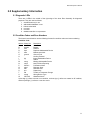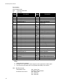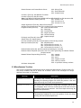
1
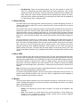
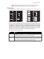
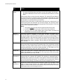
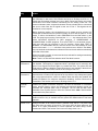
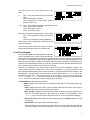
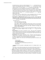
MR-2900
Fire Alarm Control Unit
OPERATOR’S
MANUAL
Revision 1
Document #: LT-2012 Dec 2008
WARNING: This manual contains information on limitations
regarding product use and function and information on the
limitations as to liability of the manufacturer. The entire
manual should be read carefully.
Copyrights and Trademarks
This manual is copyright 1994 - 2008 by Secutron Inc.
No part of this publication may be reproduced, transmitted, transcribed, stored in a
retrieval system, or translated into any language or computer language, in any form by
any means electronic, magnetic, optical, chemical, manual, or otherwise without the prior
consent of Secutron Inc.
Secutron Inc.
25 Interchange Way
Vaughan, ON L4K 5W3
Please call us at 1-888-SECUTRON (1-888-732-8876) if problems arise with the
installation or operation of these panels. For general product information, visit the
Secutron web site: www.secutron.com.
Cautions and Warnings
READ AND SAVE THESE INSTRUCTIONS. Follow the instructions in this
installation manual. These instructions must be followed to avoid damage to this
product and associated equipment. Product operation and reliability depends upon
proper installation.
DO NOT INSTALL ANY PRODUCT THAT APPEARS DAMAGED. Upon unpacking
your equipment, inspect the contents of the carton for shipping damage. If damage
is apparent, immediately file a claim with the carrier.
ELECTRICAL HAZARD - Disconnect electrical field power when making any
internal adjustments or repairs. Servicing should be performed by qualified
personnel.
STATIC HAZARD - Static electricity can damage components. Therefore, handle as
follows:
• Ground yourself before opening or installing components
• Prior to installation, keep components wrapped in anti-static material at all
times.
RADIO FREQUENCY ENERGY - This equipment generates, uses, and can radiate
radio frequency energy and if not installed and used in accordance with the
instruction manual, may cause interference to radio communications. It has been
tested and found to comply with the limits for a Class A computing device pursuant
to Subpart J of Part 15 of FCC Rules, which are designed to provide reasonable
protection against such interference when operated in a commercial environment.
Operation of this equipment in a residential area may cause interference in which
case the user at his own expense will be required to take whatever measures may
be required to correct the interference.
SYSTEM REACCEPTANCE TEST AFTER SOFTWARE CHANGES - To ensure
proper system operation, this product must be tested in accordance with NFPA721996, Chapter 7 after any programming operation or change in site-specific
software. Reacceptance testing is required after any change, addition or deletion of
system components, or after any modification, repair or adjustment to system
hardware or wiring.
All components, circuits, system operations, or software functions known to be
affected by a change must be 100% tested. In addition, to ensure that other
operations are not inadvertently affected, at least 10% of initiating devices that are
not directly affected by the change, up to a maximum of 50 devices, must also be
tested and proper system operation verified.
MR-2900 Operator’s Manual
Contents
1.0 Unit Operation .........................................................................................................................................
1.1 Power Up Sequence .......................................................................................................................
1.2 Types of Inputs ...............................................................................................................................
1.3 Status Display .................................................................................................................................
1.4 Zone LEDs ......................................................................................................................................
1.5 Buzzer.............................................................................................................................................
1.6 Operator Keys.................................................................................................................................
1.7 Alarm List ........................................................................................................................................
1.8 LCD and Keypad.............................................................................................................................
1.9 Silent Walk Test ..............................................................................................................................
2.0 Supplementary Information ......................................................................................................................
2.1 Diagnostic LEDs .............................................................................................................................
2.2 Condition Codes and Zone Numbers..............................................................................................
2.3 Miscellaneous Troubles ..................................................................................................................
1
1
1
2
2
2
3
6
7
10
11
11
11
13
i
MR-2900 Operator’s Manual
1.0 Unit Operation
The operation of the MR1 and MR2 programs are almost identical. This chapter applies to both
programs. Those functions that are different are noted.
1.1 Power Up Sequence
The power up sequence of the panel is started in the following ways: power is applied to the panel;
the hard reboot button at the top of the Inner Door is pressed; a Network Reboot command is
issued; or the panel has a fault that triggers the internal watch-dog.
The LCD will first display "INITIALIZING MEMORY PLEASE WAIT". The panel will not respond to
key presses or to zone activity. Once this step is done the panel will start to beep (buzzer does not
sound after a Network Reboot). Press Acknowledge to silence the panel.
Panels running the MR2 program will display the message "LOADING DATABASE PLEASE
WAIT". At this time, the panels will respond to key presses, but not to input circuit conditions.
Note: Since the LCD menu is unavailable, any keys requiring a privilege level other than zero to
be active will be unavailable.
When the initialization is complete, the Main Menu will be displayed on the LCD. At this time the
panel is fully operational.
1.2 Types of Inputs
There are a number of types of inputs that can be used in the system. Each has different uses and
limitations. They are:
•
•
•
•
•
•
•
Alarm: This type of input is the normal inputs to the system from smoke detectors, heat
detectors, etc. They are required to activate bells and/or strobes, as well as an LED. They
can optionally operate relays and control modules in a network, as well as releasers on
the same panel. It displays **ALARM** in the Alarm List.
Pull Station: This type of input is for pull stations. They are required to activate bells and/
or strobes, as well as an LED. They can optionally operate relays and control modules in a
network, as well as releasers on the same panel. This type cannot have a retard time. It
displays **PULL STATION** in the Alarm List.
Waterflow: This type of input is for water flow detectors. They are required to activate
bells and/or strobes, as well as an LED. They can optionally operate relays and control
modules in a network, as well as releasers on the same panel. This type displays
**WATERFLOW** in the Alarm List. Through programming, Waterflow type alarms can
make the bell circuits they activate to be non-silenceable.
Supervisory: This type of input is for items such as Shut-Off valves and Pressure sensors
for sprinkler systems. They are required to operate an LED. They cannot operate bells/
strobes but can optionally operate relays and control modules in a network, and releasers
on the same panel.
Halt: This type of input can only stop the operation of a releaser type output on the same
panel. An LED is required for annunciation of the Halt function. It will use the supervisory
LED. Note: Use of this type of input must be limited access to maintain UL listing.
Abort: This type of input can only hold the operation of a releaser type output on the same
panel. This Abort function maintains the current state of the releaser. The delay timer will
continue to run until 10 seconds are left. The releaser will resume normal operation as
soon as the input restores. An LED is required for annunciation of the Abort function. It will
use the supervisory LED.
Monitor: This type of input used to monitor the action of items such as dampers, door,
fans, etc. The supervisory LED is used. Monitor inputs can operate relays and control
modules.
1
MR-2900 Operator’s Manual
•
Non-Reporting: These are non-latching inputs. They are also referred to as Non-Fire.
There is no requirement that these inputs cause any action whatsoever. They use the
supervisory LED for annunciation. They can operate only relays and control modules. The
LEDs, relays and control modules will follow the non-reporting input's status. The LEDs,
relays and control modules operated by non-reporting inputs cannot also be operated by
Fire, Supervisory, Abort or Halt type inputs.
1.3 Status Display
The status display is the top-right section of the front panel. It is visible through the front door. It
consists of the common alarm LED, common supervisory LED, common trouble LED, AC power
LED, and the clock.
The common alarm (red) and supervisory (amber or yellow) LEDs will flash with any new alarm or
supervisory signal. The common trouble (yellow) LED will flash with any new zone trouble or a
new panel trouble, such as low battery, bell trouble, etc. The common LEDs will react to all panel
inputs plus to most conditions it displays from other panels. The AC power (green) LED is lit if AC
power is on. If the AC power has failed, the common LEDs will blink slowly instead of staying on
steady.
The clock shows the current time in 24 hour format. The flashing colon shows that the panel is
functioning correctly. If the AC power is off, the time is not displayed but the colon continues to
flash. The entire clock display flashes if the time has not been set after a Hard reboot of the panel;
also if the time is not set, the panel will show a common trouble. If any memory error occurs
(Program Checksum Error, Database Mismatch, FIFO Overflow, etc.) the clock will display 4
dashes instead of the time. The buzzer will also beep rapidly to indicate the memory error. The
clock will also display 4 dashes if any configuration parameter is changed which requires a Hard
reboot.
1.4 Zone LEDs
The zone LEDs are along the left side of the front panel. They are visible through the front door.
Each zone has an alarm (red), supervisory (yellow or amber), and trouble (yellow) LED. The alarm
and supervisory LEDs will turn on as required by the inputs. The trouble LED will light for either an
input trouble condition, a ground fault or if there is a bypass present. Use the LCD and keypad
(see section 1.8 below) to determine the exact condition. A new condition is shown by a flashing
LED. After the Acknowledge button (see section 1.6 below) has been pressed, the LED will be lit
steadily.
Note: If the buzzer is sounding on the panel, Acknowledge will silence the buzzer, but not latch the
LEDs. Press Acknowledge again to latch the LEDs.
For panels running the MR1 program, each set of zone LEDs corresponds to the input circuit. For
panels running the MR2 program, each set of zone LEDs is programmed via the database to
represent whatever logical zoning is required.
1.5 Buzzer
The buzzer gives audible indication of any new conditions in the panel. It may sound in any of four
modes. Pressing Acknowledge will silence the buzzer. (Acknowledge will need to be pressed
again to latch flashing LEDs.)
The four buzzer modes are:
•
•
2
Steady: This indicates any new fire alarm conditions. This mode can be disabled in the
database.
Fast: This indicates any critical failures that must be attended to. These failures can
include, but are not limited to memory overflow, network reboot required, database
mismatch, etc. The pattern in 50ms on/off.
MR-2900 Operator’s Manual
•
•
Medium: This indicates any new supervisory conditions. The pattern is 200ms on/off.
Slow: This indicates any new trouble conditions. The pattern in 500ms on/off.
1.6 Operator Keys
These are located below the Status Display. They are not visible through the front door. There are
Figure 1: Default Key Assignments
Figure 2: Fixed Key Assignments
12 keys, each with a yellow and green LED (some keys may have red instead of yellow LEDs).
The LEDs are used to display function status. The individual keys are located under the rectangles
marked PRESS, not under the key description. The key assignments are fixed for MR1 programs
(see Figure 1). For MR2 programs, the keys are assigned by the database. There are fixed
placement function keys as shown in Figure 2. The default layout is the same as for the MR1
program. The panel will beep once when a valid key is pressed and beep three times if an invalid
(unavailable) key is pressed. The panel will record every key press in the history.
The keys and their functions are as follows:
Key
Action
Acknowledge
First press will Silence the buzzer. The second press acknowledges new troubles
and alarms. If the buzzer is not on, any flashing LEDs will become steady. The
green LED will flash when there is something to acknowledge.
Signal
Silence
Silences the bells. The green LED will flash when Signal Silence is available. There
may be a silence inhibit before the bells can be silenced if they are activated by an
Alarm condition. The yellow LED flashes when the bells have been silenced. The
bells will reactivate if a subsequent Alarm is received by the panel.
3
MR-2900 Operator’s Manual
Key
Action
System
Reset
System Reset resets part or all of the system.
• The green LED flashes when the system, or part of the system, can be reset.
• The yellow LED flashes when there are conventional smoke detector circuits in
alarm.
Press System Reset to reset the smoke detectors. The yellow LED also flashes if
the ground fault relay is activated. Press System Reset to deactivate the ground
fault relay to check for restores and additional ground faults. If ground faults remain,
the relay will be re-activated after 5 to 30 seconds.
Pressing System Reset with no LEDs flashing will operate any relays that are not
used by the system and deactivate any Aux Power outputs. The time they remain
open is determined by the Duration time programmed. If the Duration is 0, the relay
or Aux Power output will not operate.
Notes:
1. The system cannot be reset until all circuits and devices are reset.
2. If both LEDs are flashing, the green LED function has precedence.
3. The green LED will remain flashing after System Reset is pressed until
addressable devices have had their LEDs reset.
4
Second
Stage Inhibit
Prevents the automatic operation of second stage operation. This applies only to
panels with ALERT or STAGED type bell systems. For ALERT systems, pressing
the Second Stage Inhibit will prevent the panel from going into second stage. For
STAGED systems, it will prevent the system from going to the next stage. Second
Stage Inhibit has no effect on an EVAC type bell system. The green LED will flash
when Second Stage Inhibit is available, and the yellow LED will flash when it has
been activated.
Fire Drill
Activates all the bell circuits, both regular and coded, in Alert mode. Press a second
time to have all bell circuits sound in Evacuation mode. Press a third time to end the
Fire Drill. The yellow LED will flash while the Fire Drill is happening. The Fire Drill
cannot be performed if the bells are already activated, or if AC power is off. The
Fire Drill is automatically ended if an alarm condition occurs.
Lamp Test
Flashes the panel LEDs in sequence starting with the zone alarm LEDs. Press
Lamp Test repeatedly to cycle through the zone supervisory LEDs zone trouble
LEDs, system LEDs, and Lamp Test Off.
Releaser
Disconnect
Causes the releaser circuits to ignore any new alarms. The buzzer beeps every 2
seconds while the releasers are disabled. This beeping is suppressed while a
privileged level is entered in the panel. Press again to restore normal operation.
The red LED will flash while active. If no releasers can be disconnected, Releaser
Disconnect will do nothing. This function can be set to Privilege Level 0 or 1.
Relay
Disconnect
Causes the function relays and control modules to ignore any new alarms. Press
again to restore normal operation. The yellow LED will flash while active. If no
relays nor control modules can be disconnected, Relay Disconnect will do nothing.
This function can be set to Privilege Level 0 or 1.
MR-2900 Operator’s Manual
Key
Action
Test Mode
Places panel into test mode. Press again to return to normal mode. The yellow LED
will flash while in test mode. This function can be set to Privilege Level 0 or 1. It
follows the Disconnect privilege level (set in MHI). During test mode, the remote
annunciator zone LEDs becomes non-latching for the zone(s) under test. The
common indicators, bells, relays and releasers are not activated and no commands
are sent to other units and no signal is sent out of Port 3. Test signals can be
archived or not as required.
Before beginning testing, the circuits/devices to be tested must be selected. All
unselected circuits/devices will operate normally. Be sure that the panel is in test
mode. To select circuits/devices, select PROGRAM from the Main Menu on the
LCD. The arrow keys move the cursor and the <Enter> key selects the item. Then
select INITIATING CIRCUITS for MR1 programs, or ADDRESSABLE or
CONVENTIONAL for MR2 programs. Then select TEST. For conventional circuits,
each zone will then be presented in turn for selection. Select either TEST or
NORMAL. For addressable devices, enter the device circuit and address for each
device to be tested. <Clear> will return to the previous menu. While in Test Mode,
any conventional smoke detectors activated on the test circuits will be automatically
reset after 30 seconds.
When test mode is ended, all zones and devices selected for testing automatically
return to normal operation.
Note: There is no Ground Fault isolation while Test Mode is active.
Signal
Disconnect
Disables sounding of the bells. The buzzer beeps every 2 seconds while the bells
are disabled. This beeping is suppressed while a privileged level is entered in the
panel. Press Signal Disconnect again to re-enable the bells. The yellow LED will
flash while the bells are disabled. Signal Disconnect is not available if the bells are
already activated. This function can be set to Privilege Level 0 or 1.
Common
Disconnect
Disables the relays or a City Tie Module (MRCTYB). When a MRCTYB module is
disconnected, a trouble will be reported to the city and then any subsequent signals
will not be reported until the card is re-enabled. When the relays are disabled, the
yellow LED flashes. If no relays are selected for disabling, Common Disconnect is
unavailable. This function can be set to Privilege Level 0 or 1.
General
Alarm
Initiates the general evacuation sequence. All bells are activated in Evacuation
mode, selected function relays are activated and selected releaser circuits are
activated and municipal alarm relay is activated. The red LED will flash when
activated. Press System Reset to cancel the General Alarm. Note: General Alarm
is recorded in the panel archive.
Halt
Stops the operation of all releaser type outputs on the panel. The green LED
flashes when the key is available and the yellow LED flashes when it has been
pressed.
Switch n On
Change the state of the software switch n between Auto and On. The yellow LED
will flash while the switch is forced On. The green LED will flash whenever the
switch is on, either automatically or forced. Switches can affect relays, control
modules and LEDs. This function can be set to Privilege Level 1 or 2.
5
MR-2900 Operator’s Manual
Key
Action
Switch n Off
Change the state of the software switch n between Auto and Off. The yellow LED
will flash while the switch is forced Off. The green LED will flash whenever the
switch is off, either automatically or forced. Switches can affect relays, control
modules and LEDs. This function can be set to Privilege Level 1 or 2.
Manual
Restart
This will cause the programmed control modules to reset after the system has been
reset in general. This is an MEA (New York City) requirement.
Releaser Disconnect, Relay Disconnect, Signal Disconnect, Common Disconnect, and Test Mode
can be made to time out automatically after 4 hours. Releaser Disconnect, Relay Disconnect,
Signal Disconnect, Test Mode, and Common Disconnect all use the same privilege level.
1.7 Alarm List
The Alarm List contains all the current Alarms, Supervisory Conditions and Troubles. Each panel
can be configured for one of three modes of operation: In Local mode, each panel only logs events
generated from devices that are directly connected to it. For example, a trouble generated on
Panel #1 will not be reflected in the alarm list of Panel #2. Each archive only stores locally
generated events. In Master mode, the panel defined as the master collects all network data and
maintains an alarm list of all events generated in every panel. If set to Global, every panel displays
all other panel’s events.
In all modes, the first/last entry of highest priority will be shown, instead of the Main Menu, if there
are any entries in the Alarm List. Alarms are the highest priority, Supervisory Conditions are the
2nd priority and Troubles the 3rd priority and Non-reporting signals are the lowest priority. The
LCD back light will turn on if any new entry is received. The back light will automatically turn off in
5 minutes (30 seconds if no AC) if there is no activity.
Note: A panel that does not have extended RAM memory will not show an Alarm List.
Each entry in the Alarm List consists of one screen for MR1 programs and one to three screens for
MR2 programs. Each entry will include an event screen giving a short description of the event.
MR2 programs will add device and panel message screens as required.
To view additional entries in the Alarm List when an entry is showing, press the <Scroll> (<A>)
key on the keypad. This will display the next/previous entry of the highest priority showing the
device message, if any, otherwise the event screen is shown. Press <Scroll> again to view the
next/previous entry. Use the <Up Arrow> and <Down Arrow> to rotate between screens of the
event. One can also look at the next entry using the <Right Arrow> or the previous one with the
<Left Arrow>. A summary screen will be shown when all entries have been shown. To view the
summary screen directly, press <Clear> at any time.
For more control in viewing the Alarm List, when the summary screen is showing press <Enter>.
Options for viewing All, Alarm, Supervisory, Trouble and Non-Reporting entries are provided.
Display can begin with the First or Last entry. Once viewing the events, one can look at the next
one using the <Right Arrow> or the previous one with the <Left Arrow>. <Enter> will act as
either <Left Arrow> or <Right Arrow>, whichever was pressed last. <Up Arrow> and
<Down Arrow> will rotate between pages of the event.
While viewing entries in the Alarm List, the currently displayed input can be Bypassed by pressing
the <Bypass> (<B>) key on the keypad. This will cause the panel to consider the input to be in a
normal condition.
Note: Bypass is a privileged function. A passcode will have to be entered in the system before a
Bypass will be accepted.
6
MR-2900 Operator’s Manual
The event screen of an entry shows one of two
forms:
1)
Line 1: time, sequence number, and Condition
Code
Line 2: date and Zone Number
Line 4: description of event (alarm, trouble,
ground, restore, etc.)
or 2) Line 1: time, sequence number, and Condition Code
Line 2: date and Zone Number
Line 3: description of event
Line 4: circuit/device type
The device and panel message screens, if any, show:
Line 1: time, sequence number, and Condition
Code
Lines 2 to 4: description from the database
See Section 2.2 for a description of Condition Codes
and Zone Numbers.
The summary screen shows the number of alarm,
supervisory and trouble entries in the Alarm List.
1.8 LCD and Keypad
The LCD and keypad are located below the Operator
Keys. The display may or may not be visible through
the front door. The keypad is not visible through the front door. They are used to view the status of
the panel, to view the latest events, to set the date and time and to enter a privilege passcode. The
panel will beep once when a valid key is pressed, and three times if an invalid or unavailable key is
pressed. The LCD back light will turn on if any key is pressed. The back light will automatically turn
off in 5 minutes (30 seconds if no AC) if there is no activity.
Information is presented to the user through a series of menus and information screens. The
menus present options to display other menus, show information, or request information. The
panel displays the Main Menu under normal conditions. If a privilege level has been entered, it will
be displayed in the Main Menu as well instead of the time. Menus have a ">" or "<" next to the
description of each item. Use the arrow keys on the keypad to move the cursor and press
<Enter> to select. <Clear> returns to the previous menu without changing any information and
<Home> returns to the Main Menu without changing any information.
The Main Menu has the following selections:
•
Status: Displays the current status of various parts of the panel. The following options are
available:
-- More: Displays the next screen of menu options. When the last screen of the menu is
displayed the next screen will be the first one again.
-- Misc. Trouble: Displays any troubles with the bells, releasers, AC power, batteries, etc.,
that are not shown elsewhere. Only sections in trouble will be displayed. Press
<Enter> to go to the next screen. See section 2.2 for a list of all possible messages.
-- Alarm List: Displays the Alarm List under manual control. See Alarm List above, Using
the Keypad.
-- Addressable: This menu has the following options:
Select: Displays the current status of a single device. The device address is entered into
the screen saying "circuit or circuit.device". If only a circuit number is entered, the first
7
MR-2900 Operator’s Manual
programmed device on that circuit will be displayed. If <Enter> is pressed without any
entry, the first addressable device will be displayed. <Clear> will remove any values
entered. If there is no value entered, <Clear> will return to the Status Menu. If the
selected device is not in the database, the next device in the database is shown.
The display shows the device address in the top left corner and the current condition
codes in the top right corner (see section 2.2 for a description of the condition codes).
The second line shows the headings for the third line, which contains the analog values
sent from the device. Press <Enter> to view the next device or <Clear> to get the
address input screen.
Print Sensors: Prints the analog value for every addressable smoke and thermal
detector. This is the value of the detector at the time the command is issued.
-- Conventional or Initiating Circuits: Displays the type, and alarm, trouble and ground
fault status of each of the 24 input zones (conventional zones only). Once viewing the
initiating circuit status, one can choose to look at the next circuit or the previous circuit.
<Clear> will return to the Status Menu.
The display shows:
Line 1: zone number and zone type
Line 2: factory diagnostic information
Line 4: alarm 1, alarm 2, trouble and ground fault status. Alarm 2 is used by Dual
EOLR circuits and by contact devices on Smoke Detector and Contact Device
circuits. Smoke detector circuits that have alarm verification will display the
number of failed verifications.
-- Identification: Displays a sequence of screens that provide the program and version,
the panel's serial number, database version, etc. Press <Enter> to go to the next
screen.
-- Print Database: This function is restricted to Level 1. Print the current configuration
(values entered through the LCD menu) and downloaded database of the panel to a
printer connected to the panel's printer port. The printer port is at the bottom of the main
assembly and is the one on the right.
-- Print Archive: This function is restricted to Level 1. Prints all or part of the history. A
selection menu is presented to select which kinds of events to print. The choices are:
All, Alarms, Supervisory, Trouble, Monitor, Bypass and Non-reporting.
Each entry consists of one or two lines. The information provided on the first line, from
the left, is:
1. Event Number
2. Time (24 Hour Clock)
3. Date (MM/DD/YY Format)
4. Condition Code and Zone Number (see section 2.1)
5. Description
A second line will be printed for addressable devices if a message exists in the
database.
This history is sent to the printer port(s) and to the service terminal port if Screen 1 is
active. Screen 1 of the service terminal is a copy of all items sent to the printer port.
•
8
Archive: The archive is a list of the last 900 events (approx.). These include all signals,
programming changes, time/date changes, etc., that have occurred. Test signals may or
may not be recorded but "Test On" and "Test Off" are. The archive is not lost when there is
a loss of both AC and battery power. Each entry includes a short description of the event,
and the date and time of occurrence for events occurring at or to the panel. There may be
MR-2900 Operator’s Manual
a second screen including information from the database. You can start by looking at
either the last event (newest) or the first event (oldest). When viewing the events, scroll to
the next one using the <Right Arrow> or the previous one with the <Left Arrow>.
<Enter> will act as the last <Left> or <Right> arrow key pressed. <Up Arrow> and
<Down Arrow> will flip between pages of the event.
The screen of a single screen event shows:
Line 1: time, sequence number, and date
Line 2: Condition Code and Zone Number (see section 2.1)
Line 4: description of event (alarm, trouble, ground, restore, etc.)
The first screen of a two screen event shows:
Line 1: time, sequence number, and date
Line 2: Condition Code and Zone Number (see section 2.1)
Line 3: description of event (alarm, trouble, ground, restore, etc.)
Line 4: device type
The second screen shows:
Line 1: time, sequence number, and date
Lines 2 to 4: description from the database
•
Program: Displays the Clock Menu. This menu has 2 options:
-- Date: View or change the date. The date is entered in MM.DD.YY format. Each section
of the date must be separated by a dot. Press <Enter> to accept date typed. <Clear>
will remove any digits typed. If no digits are displayed, <Clear> will return to the Clock
Menu. The date change will be recorded in the history.
-- Time: Change the time. The time is entered in HH.MM.SS format. Each section of the
time must be separated by a dot. All times are in 24 hour format. Press <Enter> to
accept time typed. <Clear> will remove any digits typed. If no digits are displayed,
<Clear> will return to the Clock Menu. The new time entered will be sent to all units on
the network, if any. A time change of greater than 5 minutes will be recorded in the
history.
•
Passcode: Allows access to privileged functions. Enter the four digit passcode. A
passcode of zero removes all privileges. Asterisks are displayed instead of the numbers to
maintain security of the passcode. <Clear> will remove any digits typed. If no digits have
been typed, <Clear> will return to the Main Menu. The panel will beep once if a valid
passcode is entered or three times if an invalid passcode is entered. An invalid passcode
will not change the current privilege of the panel. Higher level passcodes timeout after two
hours and the panel reverts to Level 0.
The number at the end of the top line shows the current privilege level. The number at the
beginning of the second line is a sequence number. This number is required if special
higher level passcodes are needed. This number will change with each successful special
passcode entered. This makes the special passcodes single use only.
9
MR-2900 Operator’s Manual
1.9 Silent Walk Test
The Silent Walk Test allows for single person testing of the system. This is done by providing an
audio output that can be used by a radio with a microphone input. The system will produce tones
through the audio output jack to give the inspector a positive indication of system behaviour. The
audio jack should be connected to the Mic In or Line In of a radio. Ensure that the radio is set to
automatically broadcast whenever a signal is sent to it. Alarm and supervisory conditions produce
a 1500 Hz tone, trouble conditions produce a 1000 Hz tone and ground conditions produce a 500
Hz tone. Two short pulses are given for a new condition and one long pulse for a restore. Tones
are generated for input circuits only. The output circuits are not part of the walk test.
To activate the walk test, first connect the radio to the audio output jack. Then activate the walk
test by pressing the Test Mode key. The yellow LED next to Test Mode will flash while the Test
Mode is active. Conventional circuits and addressable devices will need to be chosen for testing.
While selected for testing, circuit and devices will not activate relays, control modules, bells,
releasers or send signals to monitoring stations on port 3. Any LEDs assigned to the test inputs will
follow the circuit or device state. See the section on the Test Mode key on page 5 for more
information on Test Mode. All circuits and devices not chosen for testing will operate as normal.
If a printer is attached to the printer port, a print-out of all events received by the Unit can be
obtained for cross-referencing with the test procedures. Test signals will be marked as such in the
print-out.
10
MR-2900 Operator’s Manual
2.0 Supplementary Information
2.1 Diagnostic LEDs
There are 6 LEDs in the middle of the right edge of the Inner Door Assembly for diagnostic
purposes. They are used as follows:
1.
2.
3.
4.
5.
6.
extended memory in use
addressable database in use
follows coded bells
not used
not used
database transfer to co-processor.
2.2 Condition Codes and Zone Numbers
The Alarm List and Archive use the following formats for condition codes and zone numbering.
Condition Code
Archive
A
B
C
D
E
G
H
I
J
M
N
P
Q
R
S
T
U
W
Alarm List
ALARM
bypass
com
dupl
alert
ground
ilgl
msng
nofire
M.PULL
abort
halt
spv
trbl
wrong
WFLOW
Description
Alarm
Bypass
Comlink
Duplicate Addressable Device
Maintenance Alert
Ground Fault
Hot Key Pressed
Illegal Addressable Device
Switch
Missing Addressable Device
Non-Fire/Non-Reporting
Pull Station Alarm
Releaser Abort
Releaser Halt
Supervisory
Trouble or Parameter Change
Wrong Device Type
Waterflow Alarm
A plus sign (+) refers to a new or on condition, a minus sign (-) refers to a restoral or off condition,
and an equal sign (=) refers to a one time event.
11
MR-2900 Operator’s Manual
Zone Number
PPP:ZZ.SSS Format:
PPP
Control Panel Number
ZZ
Panel Zone
Panel
Zone
Description
Panel
Zone
Description
0
1
2
3
4
General Alarm
Initiating Circuit 1
Initiating Circuit 2
Initiating Circuit 3
Initiating Circuit 4
53
54
55
59
60
5
6
Initiating Circuit 5
Initiating Circuit 6
61
7
Initiating Circuit 7
8
9
10
Initiating Circuit 8
Initiating Circuit 9
Initiating Circuit 10
11
12
Initiating Circuit 11
Initiating Circuit 12
13
14
15
16
17
Initiating Circuit 13
Initiating Circuit 14
Initiating Circuit 15
Initiating Circuit 16
Initiating Circuit 17
18
Initiating Circuit 18
19
20
Initiating Circuit 19
Initiating Circuit 20
21
Initiating Circuit 21
891
Time/Date Change
22
Initiating Circuit 22
1
Hot Key Activation
23
Initiating Circuit 23
1
Memory Overflow
24
Initiating Circuit 24
92
1
Network Reboot
50
Network Verify
931
New Program
51
Comlink 1
941
Network Reboot Required who
52
Comlink 2
951
Network Reboot Required why
641
651
66
67
691
71
80
81
82
83
84
2
851
863
87
88
90
1
91
Comlink 3
Comlink 6
Printer Port
Addressable Modules Comlink
Output (bell/releaser)
Supervision
Auxiliary Power Supervision
Program Checksum
Database Checksum
AC Power
Low Battery
Program Restart
Network Ground Fault
Privilege Level
1st Stage Alarm
2nd Stage Alarm
Switch
Test Mode
Erase Configuration
Change Configuration
Passcode Tamper
Database Loaded
Notes:
1. These zones do not restore.
2. Privilege Level 0 generates a restore signal; all others generate a trouble signal.
3. This zone does not restore and is not repeated sequentially in the archive.
SSS
Sub-Zone Number
Addressable Circuit:
Dual End-of-Line Circuit:
12
000 - Wiring Fault
All Others - Device Number
000 - Wiring Fault
001 - Switch #1
002 - Switch #2
MR-2900 Operator’s Manual
Smoke Detector and Contact Device Circuit:
000 - Wiring Fault
001 - Smoke Detector
002 - Contact Device
Comlink 1 (Zone 51): Unit Network ID number
Comlink 3 (Zone 53): Unit ID number
Note: Only MR-2614, MR-2644, MR2801-MR and MR-2806-MR use IDs other than 000.
Addressable Module Comlink (Zone 59):
001 - Circuits 1 to 8
002 - Circuits 9 to 16
003 - Circuits 17 to 24
Output Supervision (Zone 60): Output Circuit Number
Auxiliary Power Supervision (Zone 61): Auxiliary Power Circuit Number
Program Re-start (Zone 69):
000 - Power On/Hard reboot
001 - Watchdog
002 - Clock Monitor
003 - Illegal Instruction
004 - Unused Interrupt
005 - Orphan Interrupt
Privilege Level (Zone 80): Level Set
Switch (Zone 83): Switch Number
Hot Key Activation (Zone 90): Function Number of the Hot key pressed
Memory Overflow (Zone 91):
000 - MR-2900 panel
001 - CoProcessor for circuits 1..8
002 - CoProcessor for circuits 9..16
003 - CoProcessor for circuits 17..24
Network Reboot (Zone 92): Unit ID of panel broadcasting the command
Network Reboot Required (Zone 94): Unit ID of panel generating the Network Reboot
Required trouble
Network Reboot Required Why (Zone 95):
001 - network
002 - network
003 - port 3
006 - negative counter
008 - memory overflow
009 - co-processor memory overflow
All Others: Always 000
2.3 Miscellaneous Troubles
This is a list of all possible messages that can be displayed by Miscellaneous Trouble on the LCD.
Only those conditions that are in trouble will be shown. Some of the messages are always
displayed if the panel is in Test Mode.
Message
Description
PROGRAM checksum
The memory chip containing the operating program has an error in it.
Reloading the operating program will correct this problem. If this error
keeps reoccurring, the unit will need replacement.
EEPROM checksum
The memory chip containing the configuration information has an error
in it. Changing a value of an item set through the LCD menu will cause
the panel to create a new checksum. If this error keeps reoccurring, the
unit will need replacement.
DATABASE checksum
The memory chip containing the downloaded database has an error in
it. Reloading the database will correct this problem. If this error keeps
occurring, the unit will need replacement.
13
MR-2900 Operator’s Manual
Message
14
Description
EEPROM failure
The memory chip containing the configuration information is not working
correctly. It will need to be erased. This requires a Level 9 passcode.
Erasing the EEPROM will lose ALL information in the EEPROM. This
includes the configuration information, the panel serial number and the
archive. Be sure to record this information before you erase the
EEPROM. Contact a service representative for help and a Level 9
passcode.
not enough EEPROM
to save addressable
settings
The panel has a 64k EEPROM and is running an MR2 program. The
addressable device bypasses and the manual operation of control
modules requires a 256k EEPROM for the settings to be retained when
the panel is rebooted. Note: This will not cause a common trouble on
the panel.
program mismatch
The version number stored in the EEPROM is different from the version
number in the program. Either reload the old program or erase the
EEPROM. Erasing the EEPROM requires Privilege Level 9. Erasing the
EEPROM will lose ALL information in the EEPROM. This includes the
configuration information, the panel serial number and the archive. Be
sure to record this information before you erase the EEPROM. Contact
a service representative for help and a Level 9 passcode.
hardware mismatch
The hardware listed in the database does not match the hardware listed
in the panel. Correct the database and reload.
no database loaded
The panel does not have a database in memory. Load a database into
the panel.
wrong database
version or database
mismatch
The database is the incorrect version for the operating program running.
Download a database with the same version number as the operating
program.
no database for
this panel
The panel contains a valid database, but the database does not contain
the information for this panel. Either change the panel ID to the correct
value, or load a database that includes the panel's ID.
CoProcessor ?..?
off line
This is a major error. The CoProcessor for the circuits listed (1..8,
9..16, or 17..24) is not communicating with the main CPU. This
message will be repeated for each CoProcessor that is off-line. Devices
are not being monitored by the system. If a reboot of the MR-2900 does
not fix the problem, the addressable input module for those circuits will
need to be replaced.
CoProcessor ?..?
memory overflow
The CoProcessor for the addressable circuits listed (1..8, 9..16, or
17..24) has had a memory overflow. A reboot of the MR-2900 should be
done to correct any problems. This message will be repeated for each
CoProcessor that has overflowed.
low battery
The battery needs recharging or replacement.
battery charger not
calibrated
The battery charger needs to be calibrated to provide proper
supervision of the batteries. To calibrate the charger, disconnect the
batteries and select PROGRAM/BATTERY/CALIBRATE from the LCD
menu.
MR-2900 Operator’s Manual
Message
BBBBBBBBAA
1234567812
..........
Description
List the status of the 8 bell circuits and the 2 auxiliary power circuits.
Each column represents one circuit. A dot (.) indicates a normal
condition, an S indicates a short, an O indicates an open and a G
indicates a ground. Auxiliary power circuits are not supervised for
opens. A bell that has been installed with the polarity the wrong way
may appear as a short on the bell circuit. Note: This message will
always be shown if the panel is in Test Mode.
SE2910 not
installed
The MR-2910 Network Board has not been installed. The network
cannot be used unless this board is installed.
port 1 panel ?
off line
This Control or Annunciator Unit is not reporting in over network port 1.
This message will be repeated for each panel that is off line.
port 2 off line
The network communications on port 2 have stopped.
port 3 off line
The communications on port 3 have stopped.
wrong port 3
program
The port 3 selections in the MHI database do not match the firmware
option. Either correct the database or load the correct firmware.
BBBBBBBBFFFF
123456781234ASTWGL
The current status of the relays in the system. Each column represents
one relay. A dot (.) will appear under each relay that is off and an
asterisk (*) will appear under each relay that is currently switched on.
Note: This message appears in Test Mode only.
B
F
A
S
Bell Circuit 1 to 8
Function Relay 1 to 4
Alarm Relay
Supervisory Relay
T
W
G
L
Trouble Relay
Walk Test Relay
Ground Fault Relay
LCD Back Light Relay
passcode tamper
There have been 3 consecutive attempts to enter an invalid passcode.
watchdog disabled
The watchdog causes the panel to be reset if it fails to operate correctly.
If the watchdog is disabled, the panel will not automatically reboot if it
fails to operate correctly.
NETWORK REBOOT
required
There has been a loss of communications on the network resulting in
lost frames. The panel ID listed is the panel that detected the problem.
This trouble will be sent to all other panels and annunciators on the
network., Select PROGRAM/PORTS/NETWORK/REBOOT from the
LCD menu to send the reboot command to all panels.
network verify ?
missing
The Network Verify feature has detected that the panel listed is not
reporting in. This is indicative of a communications error.
network verify ?
illegal
The Network Verify feature has detected that the panel listed is not this
panel’s database. Update the database in this panel. Remember that it
is recommended that all panels be downloaded with the same database
for correct operation.
network verify ?
version
The Network Verify feature has detected that the panel listed is running
a different version of the operating program database. Update all panels
in the network to use the same operating program and database.
15
MR-2900 Operator’s Manual
Message
16
Description
negative counters
This is indicative of a network communications fault. Network Reboot
Required will automatically be generated by the unit.
time not set
The time has not been set since the panel has been Rebooted. The time
displayed on the clock may be wrong. Enter the correct time.
conventional
circuit bypassed
One or more conventional circuits have been bypassed. To view which
circuits have been bypassed, select PROGRAM/CONVENTIONAL/
BYPASS/INDIVIDUAL from the LCD menu.
illegal
addressable
devices
There are addressable devices connected to the panel that are not
included in the downloaded database.
addressable
devices
bypassed
One or more addressable devices have been bypassed. To view which
devices have been bypassed, select PROGRAM/ADDRESSABLE/
BYPASS/OFF from the LCD menu.
manual control
modules
One or more control modules have been forced either on or off. To view
which control modules are forced, select PROGRAM/ADDRESSABLE/
CONTROL MODULES/OFF from the LCD menu.
manual function
relays
One or more general function relays have been forced either on or off.
To view which relays are forced, select PROGRAM/RELAYS/MODES/
INDIVIDUAL from the LCD menu.
manual switches
One or more switches with timers have been forced either on or off. This
is not shown for switches that do not have timers. To view which
switches are forced, select PROGRAM/SWITCHES/INDIVIDUAL from
the LCD menu.
MEMORY OVERFLOW
An event happened that caused an out of memory condition. This
means that an event has been lost by the panel. The printer and Port 3
will discard frames to help relieve the memory problem. The panel will
have to have a Hard reboot done.
memory lockout
The extended memory lockout has timed out. The panel will need a
Hard Reboot to correct this problem. Please notify Secutron of the
occurrence of this error. Include in your report the panel serial number
and the name, date and time of the operating program.
serial printer
off-line
The MR-2920 strip printer is not responding to the panel. Ensure that
the ribbon cable is not broken. The MR-2920 may need to be replaced.
serial printer
out of paper
The MR-2920 is out of paper. Place a new roll of paper (SE1002) into
the printer.
parallel printer
off-line
The printer connected to the printer port is not responding to the panel.
Ensure that the cable is not broken. If no printer is being used, reboot
the panel to clear this trouble.
parallel printer
out of paper
The printer connected to the printer port is out of paper. Add paper to it.
MR-2900 Operator’s Manual
Message
Description
coprocessor class
changed
One or more of the addressable input circuit modules have been
changed from either Class A or B to the other. Reboot the panel to clear
this trouble.
not enough ram
The operating program requires more extend RAM then the panel
actually has. Certain addressable functions and/or the alarm list may not
work. Basic fire detection will continue to operate. Upgrade the RAM in
the panel to clear this trouble. This should only appear when upgrading
the operating program of panels that have been in the field for a number
of years.
17
© 2007 Secutron, Inc.
No part of this publication may be reproduced, transmitted,
transcribed, stored in a retrieval system, or translated into
any language or computer language, in any form by any
means electronic, magnetic, optical, chemical, manual, or
otherwise without the prior consent of Secutron.
Canada
25 Interchange Way
Vaughan, ON L4K 5W3
Tel:
(888) SECUTRON
(888) 732-8876
Fax:
(905) 660-4113
U.S.A
4575 Witmer Industrial Estates
Niagara Falls, New York 14305
Tel:
(888) SECUTRON
(888) 732-8876
Fax:
(905) 660-4113