1
Network
Adapter Cards
®
AT-2400 Series
AT-2450/AT-2451 Series
AT-2500/AT-2501 Series
AT-2700/AT-2701 Series
AT-2745/AT-2746 Series
AT-2801FX
AT-2915 Series
AT-2916T Series
AT-2930 Series
AT-2970/AT-2971 Series
Installation
Guide
BOOK II
FOR MICROSOFT WINDOWS FOR WORKGROUPS
3.11, MICROSOFT DOS CLIENT 3.0, NOVELL
NETWARE 4.X, 5.X, AND 6.X, LINUX 2.2X AND 2.4X,
AND BOOT ROM OPERATING SYSTEMS
PN 613-50383-00 Rev D
Copyright © 2004 Allied Telesyn, Inc.
960 Stewart Drive Suite B, Sunnyvale, CA 94085 USA
All rights reserved. No part of this publication may be reproduced without prior written permission from Allied Telesyn, Inc.
Netscape Navigator is a registered trademark of Netscape Communications Corporation. All other product names, company
names, logos or other designations mentioned herein are trademarks or registered trademarks of their respective owners.
Allied Telesyn, Inc. reserves the right to make changes in specifications and other information contained in this document without
prior written notice. The information provided herein is subject to change without notice. In no event shall Allied Telesyn, Inc. be
liable for any incidental, special, indirect, or consequential damages whatsoever, including but not limited to lost profits, arising
out of or related to this manual or the information contained herein, even if Allied Telesyn, Inc. has been advised of, known, or
should have known, the possibility of such damages.
Electrical Safety and Emission
Statement
Standards: This product meets the following standards.
U.S. Federal Communications Commission
Radiated Energy
Note: This equipment has been tested and found to comply with the limits for a Class A digital device pursuant to Part 15 of the
FCC Rules. These limits are designed to provide reasonable protection against harmful interference when the equipment is
operated in a commercial environment. This equipment generates, uses, and can radiate radio frequency energy and, if not
installed and used in accordance with this instruction manual, may cause harmful interference to radio communications.
Operation of this equipment in a residential area is likely to cause harmful interference in which case the user will be required to
correct the interference at his own expense.
Note: Modifications or changes not expressly approved by the manufacturer or the FCC can void your right to operate this
equipment.
Industry Canada
This Class A digital apparatus meets all requirements of the Canadian Interference-Causing Equipment Regulations.
Cet appareil numérique de la classe A respecte toutes les exigences du Règlement sur le matériel brouilleur du Canada.
RFI Emission
EN55022 Class A, EN61000-3-2, EN61000-3-3 1
Warning: In a domestic environment this product may cause radio interference in which case the user may be required to take
adequate measures. 2
Immunity
EN55024 3
Electrical Safety
EN60950, UL 1950 (UL/cUL) 4
Laser
EN60825 5
Important: Appendix B contains translated safety statements for installing this equipment. When you see the , go to Appendix
B for the translated safety statement in your language.
Wichtig: Anhang B enthält übersetzte Sicherheitshinweise für die Installation dieses Geräts. Wenn Sie sehen, schlagen Sie in
Anhang B den übersetzten Sicherheitshinweis in Ihrer Sprache nach.
Vigtigt: Tillæg B indeholder oversatte sikkerhedsadvarsler, der vedrører installation af dette udstyr. Når De ser symbolet , skal
De slå op i tillæg B og finde de oversatte sikkerhedsadvarsler i Deres eget sprog.
Belangrijk: Appendix B bevat vertaalde veiligheidsopmerkingen voor het installeren van deze apparatuur. Wanneer u de ziet,
raadpleeg Appendix B voor vertaalde veiligheidsinstructies in uw taal.
Important: L'annexe B contient les instructions de sécurité relatives à l'installation de cet équipement. Lorsque vous voyez le
symbole , reportez-vous à l'annexe B pour consulter la traduction de ces instructions dans votre langue.
Tärkeää: Liite B sisältää tämän laitteen asentamiseen liittyvät käännetyt turvaohjeet. Kun näet -symbolin, katso käännettyä
turvaohjetta liitteestä B.
Importante: l’Appendice B contiene avvisi di sicurezza tradotti per l’installazione di questa apparecchiatura. Il simbolo , indica
di consultare l’Appendice B per l’avviso di sicurezza nella propria lingua.
Viktig: Tillegg B inneholder oversatt sikkerhetsinformasjon for installering av dette utstyret. Når du ser , åpner du til Tillegg B
for å finne den oversatte sikkerhetsinformasjonen på ønsket språk.
Importante: O Anexo B contém advertências de segurança traduzidas para instalar este equipamento. Quando vir o símbolo ,
leia a advertência de segurança traduzida no seu idioma no Anexo B.
Importante: El Apéndice B contiene mensajes de seguridad traducidos para la instalación de este equipo. Cuando vea el símbolo
, vaya al Apéndice B para ver el mensaje de seguridad traducido a su idioma.
Obs! Bilaga B innehåller översatta säkerhetsmeddelanden avseende installationen av denna utrustning. När du ser , skall du gå
till Bilaga B för att läsa det översatta säkerhetsmeddelandet på ditt språk.
3
Table of Contents
Electrical Safety and Emission Statement ............................................................................................................................................... 3
Preface ...................................................................................................................................................................................................................... 9
Purpose of this Guide ........................................................................................................................................................................................... 9
How This Guide is Organized ...........................................................................................................................................................................10
Document Conventions ....................................................................................................................................................................................11
Where to Find Related Guides .........................................................................................................................................................................12
Contacting Allied Telesyn .................................................................................................................................................................................13
Online Support..............................................................................................................................................................................................13
E-mail and Telephone Support ...............................................................................................................................................................13
Returning Products......................................................................................................................................................................................13
For Sales or Corporate Information .......................................................................................................................................................13
Obtaining Management Software Updates .......................................................................................................................................13
Tell Us What You Think...............................................................................................................................................................................13
Chapter 1
Installing the Network Adapter Card .......................................................................................................................................................15
Verifying Package Contents......................................................................................................................................................................15
Reviewing Safety Precautions .........................................................................................................................................................................16
Installing a Network Adapter Card ................................................................................................................................................................17
Installing an AT-2801FX .............................................................................................................................................................................19
Chapter 2
Diagnostics ...........................................................................................................................................................................................................21
Running Diagnostics ...........................................................................................................................................................................................22
For the AT-24xx Series ................................................................................................................................................................................22
For the AT-24xx, AT-25xx, AT-27xx, AT-2915, and AT-2930 Series .............................................................................................22
For the AT-2801FX Series...........................................................................................................................................................................23
For the AT-2916T, AT-2970, and AT-2971 Series ...............................................................................................................................24
Loopback Test for Fiber Adapters ..........................................................................................................................................................25
Repeater Test for Copper Adapters .......................................................................................................................................................27
Failure of a Test .............................................................................................................................................................................................29
Additional Functions of the Diagnostics Program ...................................................................................................................................31
Checking Other Displays and Data ........................................................................................................................................................31
Main Program ................................................................................................................................................................................................31
Reading Sensor Data...................................................................................................................................................................................32
Reading Configuration Data.....................................................................................................................................................................33
Reading VPD Data ........................................................................................................................................................................................34
5
Table of Contents
Chapter 3
Microsoft DOS Client 3.0 ................................................................................................................................................................................ 37
Installing a Network Adapter Driver ............................................................................................................................................................. 38
Sample Configuration ................................................................................................................................................................................ 39
Removing a Network Adapter Driver ........................................................................................................................................................... 40
Chapter 4
Microsoft Windows for Workgroups ....................................................................................................................................................... 41
Installing a Network Adapter Driver ............................................................................................................................................................. 42
Installing NDIS2 and ODI Drivers ........................................................................................................................................................... 42
AT-245x, AT-27xx NDIS2 Keywords ....................................................................................................................................................... 44
Sample PROTOCOL.INI File....................................................................................................................................................................... 44
NetWareIPXODI Support for NetWare 3.x........................................................................................................................................... 45
NetWare IPXODI Support For NetWare 4.x......................................................................................................................................... 46
Sample NET.CFG and PROTOCOL.INI Files.......................................................................................................................................... 47
Removing a Network Adapter Driver ........................................................................................................................................................... 48
Chapter 5
Novell Netware ................................................................................................................................................................................................... 49
Installing a Network Adapter Driver on Novell Netware 4 Server ..................................................................................................... 50
Files Needed for Installation .................................................................................................................................................................... 50
New Server Installation.............................................................................................................................................................................. 50
Installing the Drivers................................................................................................................................................................................... 51
Multiple Adapters ........................................................................................................................................................................................ 53
Removing an Adapter Driver from Novell Netware 4 Server....................................................................................................... 54
Installing a Network Adapter Driver on Novell NetWare 5.x/6.x ........................................................................................................ 55
Files Needed for Installation .................................................................................................................................................................... 55
New Server Installation.............................................................................................................................................................................. 55
Manual Installation...................................................................................................................................................................................... 56
Multiple Adapters ........................................................................................................................................................................................ 58
Removing an Adapter Driver from Novell Netware 5/6 Server................................................................................................... 60
Chapter 6
Linux ........................................................................................................................................................................................................................ 61
Installing the ATNIC Driver for AT-2450/AT-2451, AT-2700/ AT-2701 Series,
and AT-2745/AT-2746 Series PCI Ethernet Adapters ............................................................................................................................ 62
Limitations...................................................................................................................................................................................................... 62
Building the Driver ...................................................................................................................................................................................... 62
Installing the Driver..................................................................................................................................................................................... 62
Dynamic Loading......................................................................................................................................................................................... 63
Changing Configuration Settings.......................................................................................................................................................... 63
Installing a Linux Driver for an AT-2915 and AT-2930 Series Network Adapter ........................................................................... 64
Limitations...................................................................................................................................................................................................... 64
Building the Driver ...................................................................................................................................................................................... 64
Installing the Driver..................................................................................................................................................................................... 64
Dynamic Loading......................................................................................................................................................................................... 64
Module Parameters..................................................................................................................................................................................... 65
Installing Linux Driver on a AT-2916T, AT-2970, or AT-2971 Series Adapters ............................................................................... 67
Overview ......................................................................................................................................................................................................... 67
Required FIles................................................................................................................................................................................................ 67
Installation Guidelines ............................................................................................................................................................................... 67
Installing the Driver..................................................................................................................................................................................... 67
Loading the Module Manually................................................................................................................................................................ 68
Unloading the Module............................................................................................................................................................................... 68
Driver Parameters ........................................................................................................................................................................................ 68
6
Network Adapter Card Installation Guide - Book II
Chapter 7
AT-2971 Solaris Sparc ......................................................................................................................................................................................69
Installing a Solaris Sparc Driver on a AT-297x Series Adapter .............................................................................................................70
Overview..........................................................................................................................................................................................................70
Required Files ................................................................................................................................................................................................70
Installing the Driver .....................................................................................................................................................................................70
Using pkgadd.................................................................................................................................................................................................70
Procedures During Installation................................................................................................................................................................72
Removing the Driver ...........................................................................................................................................................................................73
Adding Adapters ..................................................................................................................................................................................................74
Installing the Adapter using pkgrm and pkgadd .............................................................................................................................74
Driver Parameters ................................................................................................................................................................................................75
To use the Unload and Reoad Method.................................................................................................................................................75
Per-port Parameters ....................................................................................................................................................................................76
Per-adapter Parameters .............................................................................................................................................................................80
Global Driver Parameters...........................................................................................................................................................................85
Dual Net Operation Mode .................................................................................................................................................................................86
VLAN Configuration and Parameters ............................................................................................................................................................90
VLAN Configuration Using Script skge_vlan_congif .......................................................................................................................90
Manual VLAN Configuration.....................................................................................................................................................................96
VLAN Configuration in Single Net Mode .............................................................................................................................................97
Parameters......................................................................................................................................................................................................98
Additional Parameters............................................................................................................................................................................. 100
VLAN Configuration in Dual Net Mode ............................................................................................................................................. 102
PCI Hot Plug and Power Management ...................................................................................................................................................... 104
PCI Hot Plug................................................................................................................................................................................................. 104
Power Management................................................................................................................................................................................. 104
Tuning ................................................................................................................................................................................................................... 106
“ndd” Support .................................................................................................................................................................................................... 107
Virtual Cable Tester (TM) (VCI) ...................................................................................................................................................................... 109
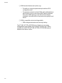
Troubleshooting ................................................................................................................................................................................................ 112
Error Messages ................................................................................................................................................................................................... 113
Chapter 8
BootROM ............................................................................................................................................................................................................. 115
Managed Boot Agent............................................................................................................................................................................... 115
Installing a BootROM ....................................................................................................................................................................................... 117
Installation ................................................................................................................................................................................................... 117
BootROM Parameter ................................................................................................................................................................................ 119
Appendix A
Translated Safety and Emission Information ................................................................................................................................... 121
7
Preface
This installation guide contains instructions on how to install an Allied
Telesyn adapter card in your computer and how to load the adapter
driver. This guide also explains the AT-Setup program which simplifies
the task of installing or updating an adapter driver.
Purpose of this Guide
This guide is intended for anyone who needs to install or update a
network adapter card or driver on their PC-compatible system.
9
Preface
How This Guide is Organized
This guide contains the following chapters and appendix:
Chapter 1, Installing the Network Adapter Card, describes how to install
an adapter card into your computer.
Chapter 2, Diagnostics, contains procedures for running and using the
diagnostics program for your Allied Telesyn adapter.
Chapter 3, Microsoft DOS Client 3.0, contains procedures for manually
installing a network adapter driver on a PC-compatible system running
Microsoft DOS Client 3.0.
Chapter 4, Microsoft Windows for Workgroups, contains the procedures
for installing and removing a network adapter driver on a PC-compatible
running Windows for Workgroups 3.11.
Chapter 5, Novell Netware, contains the procedures for installing an
adapter driver on a Novell Netware system.
Chapter 6, Linux, contains the procedures for installing an adapter driver
on a Linux system.
Chapter 7, AT-2971 Solaris Sparc, contains the procedures for installing
the driver for an AT-2971 adapter in a Solaris Sparc system.
Chapter 8, BootROM, contains the procedures for installing and
configuring a BootROM on an Allied Telesyn Network Adapter Card.
Appendix A, Translated Safety and Emission Information, contains multilanguage translations of the safety and emission statements in this
guide.
10
Network Adapter Card Installation Guide - Book II
Document Conventions
This guide uses several conventions that you should become familiar
with before you begin to install the product.
Note
Notes provide additional information.
Warning
Warnings inform you that performing or omitting a specific action
may result in bodily injury.
Caution
Cautions inform you that performing or omitting a specific action
may result in equipment damage or loss of data.
11
Preface
Where to Find Related Guides
The Allied Telesyn web site at www.alliedtelesyn.com offers you an easy
way to access the most recent documentation, software updates, and
technical information for all of our products. The documents provided
on our web site are available as PDF files.
12
Network Adapter Card Installation Guide - Book II
Contacting Allied Telesyn
This section provides Allied Telesyn contact information for technical
support as well as sales or corporate information.
Online Support
E-mail and
Telephone
Support
Returning
Products
You can request technical support online by accessing the Allied Telesyn
Knowledge Base from the following web site at kb.alliedtelesyn.com.
You can use the Knowledge Base to submit questions to our technical
support staff and review answers to previously asked questions.
For Technical Support via e-mail or telephone, refer to the “Support &
Services” section of the Allied Telesyn web site at
www.alliedtelesyn.com.
Products for return or repair must first be assigned a Return Materials
Authorization (RMA) number. A product sent to Allied Telesyn without a
RMA number will be returned to the sender at the sender’s expense.
To obtain a RMA number, contact Allied Telesyn’s Technical Support at
our web site at www.alliedtelesyn.com
For Sales or
Corporate
Information
Obtaining
Management
Software
Updates
You can contact Allied Telesyn for sales or corporate information at our
web site at www.alliedtelesyn.com. To find the contact information for
your country, select “Contact Us” then “Worldwide Contacts”.
New releases of management software for our managed products can
be downloaded from either of the following Internet sites:
❑ Allied Telesyn web site: www.alliedtelesyn.com
❑ Allied Telesyn FTP server: ftp://ftp.alliedtelesyn.com
If you would prefer to download new software from the Allied Telesyn
FTP server from your workstation’s command prompt, you will need FTP
client software and you will be asked to log in to the server. Enter
‘anonymous’ as the user name and your email address for the password.
Tell Us What
You Think
If you have any comments or suggestions on how we might improve this
or other Allied Telesyn documents, please fill out the General Enquiry
Form online. This form can be accessed by selecting “Contact Us” from
www.alliedtelesyn.com.
13
Chapter 1
Installing the Network Adapter
Card
This chapter contains instructions for installing the following Allied
Telesyn network adapter cards:
❑ AT-2400 Series
❑ AT-2450/AT-2451 Series
❑ AT-2500/AT-2501 Series
❑ AT-2700/AT-2701 Series
❑ AT-2745/AT-2746 Series
❑ AT-2801FX Series
❑ AT-2915 Series
❑ AT-2916T Series
❑ AT-2930 Series
❑ AT-2970/AT-2971 Series
Verifying
Package
Contents
Make sure the following items are included in your package. If any item
is missing or damaged, contact your Allied Telesyn sales representative
for assistance.
❑ Allied Telesyn Network Adapter Card
❑ CardAssistant CD
❑ Wake-on-LAN cable (AT-2450, AT-2451, AT-2500, AT-2501,
AT-2700, and AT-2701 Series only)
❑ Low Profile Bracket (AT-2451FTXv2, AT-2701FTXv2, AT-2701FXv2,
AT-2916T Series only)
15
Installing the Network Adapter Card
Reviewing Safety Precautions
Please review the following safety precautions before you install the
network adapter card.
Warning
This is a “Class 1 LED product”. 6
Warning
Do not stare into the laser beam. (AT-2450FT, AT-2450FL, AT-2451FTX,
AT-2700FX, AT-2701, AT-2970, AT-2971SX Series only) 7
Warning
Lightning Danger: Do not work on this equipment or cables during
periods of lightning activity. 8
Caution
Operating Temperature: This product is designed for a maximum
ambient temperature of 40 degrees C. 9
Caution
All Countries: Install this product in accordance with local and
National Electric Codes. 10
16
Network Adapter Card Installation Guide - Book II
Installing a Network Adapter Card
This section explains how to install a network adapter card in most PCcompatible computers.
Note
If you are installing an AT-2801FX CardBus PC Card, refer to Installing
an AT-2801FX on page 19.
To install the adapter card, perform the following procedure:
1.
Shutdown your PC and disconnect the power cord from the outlet.
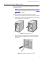
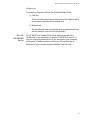
2.
Remove the PC’s cover by removing the screws from the chassis and
gently sliding off the cover. See Figure 1.
Figure 1 Removing the PC Cover
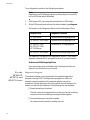
3.
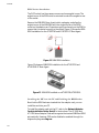
Select an empty, non-shared PCI slot and remove the faceplate.
Keep the faceplate in a safe place. You may need it for future use.
See Figure 2.
Figure 2 Removing the Faceplate From PCI Slot
17
Installing the Network Adapter Card
Note
If you cannot locate or know how to find an PCI slot, refer to the
documentation that came with your PC.
4.
Remove the network adapter card from the shipping package and
store the packaging material in a safe location.
Caution
Wear a grounding device and observe electrostatic discharge
precautions when installing the network adapter card in a PC.
Failure to observe this caution could result in damage to the adapter
card.
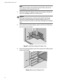
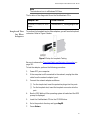
5.
Gently insert the network adapter card into the PCI slot. Make sure
the card is securely seated.
Figure 3 Inserting the Network Adapter Card
6.
Secure the network adapter card to the chassis with a Phillips-head
screw, not provided.
Figure 4 Securing the Adapter Card
18
Network Adapter Card Installation Guide - Book II
7.
For the AT-2450, AT-2500, or AT-2700 Series adapters, to use the
adapter card’s Wake-on-LAN feature in your computer using an
Advanced Configuration and Power Interface (ACPI), you must
connect the Wake-on-LAN cable to the Wake-on-LAN connector on
the adapter card and to the Wake-on-LAN connector on the
motherboard of the computer. For the location of the Wake-on-LAN
connector on the motherboard, refer to the documentation that
came with your computer.
The AT-2501, AT-2451F, AT-2701, AT-2915, AT-2916T, AT-2930, AT2970, and AT-2971 do not require the optional external Wake-onLAN cable. These devices are PCI 2.2 compliant and can use the PCI
2.2 BUS for Wake-on-LAN features.
8.
Replace the PC’s cover and secure it with the screws removed in
Step 2.
9.
Connect the adapter card to the network by connecting the
appropriate data cable.
10. Power ON the PC.
You are now ready to install the network adapter driver. Refer to the
appropriate chapter for your operating system.
Installing an
AT-2801FX
The AT-2801FX is a CardBus PC Card that must be inserted into a
CardBus slot. If you are unable to insert an AT-2801FX into your PC, it
may not support a CardBus device. If you are unsure if your computer
will support a CardBus interface, contact your PC manufacturer to
determine if your computer supports CardBus Type II devices.
19
Chapter 2
Diagnostics
This chapter contains the following procedures:
❑ Running Diagnostics on page 22
❑ Additional Functions of the Diagnostics Program on page 31
21
Diagnostics
Running Diagnostics
For the AT-24xx
Series
For the
AT-24xx,
AT-25xx,
AT-27xx,
AT-2915, and
AT-2930 Series
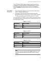
Command line option for diag.exe:
-d
Run command-line diagnostics
-e
Enable External Loopback Test when running diagostics
-pme Enable PME OverWrite mode
-nopxe Disable boot ROM support
-pxe Enable boot ROM support
-0
Auto-negotiation
-1
100Mb/half-duplex
-2
100Mb/full-duplex
-3
10Mb/half-duplex
-4
10Mb/full-duplex
-5
Enable copper port as default
-6
Enable fiber port as default
The diagnostics utulity is useful for setting the Speed/Duplex and
BootROM. You can also insure proper operation of the network adapter
card. This utility is located on the CardAssistant CD or the driver
installation disk.
Speed/Duplex
This option allows the user to configure speed and duplex to one of the
available options. The options for speed and duplex vary depending on
adapter model
BootROM Port
The BootROM port setting is only for multi-port AT-2450, AT-2700, and
AT-2745 Series PCI Ethernet Adapter Cards without integrated Manage
BootROM, specifically the AT-2450FTX, AT-2700FTX, and AT-2745FX.
When using one of these three adapters in a BootROM configuration, it
may be necessary to change these settings. For any other AT-2450 or
AT-2700 Series PCI Ethernet Adapter Card the BootROM Port setting
should not be changed.
BootROM
This feature is only available for the AT-2500 and AT-2501TX Series
Adapters. Using the Diagnostics program (diag25.exe) set BootROM to
enable.
22
Network Adapter Card Installation Guide - Book II
Diagnostics
There are two diagnostic utilities, Card Test and Network Test.
❑ Card Test
This test checks several parts and functions of the adapter card to
ensure proper operation of the adapter card.
❑ Network test
This test allows the user to send and receive raw packets without
a driver loaded to check the card functionality.
For the
AT-2801FX
Series
The AT-2801FX is a CardBus PC Card that must be inserted into a
CardBus slot. If you are unable to insert an AT-2801FX into your PC, it
may not support a CardBus device. If you are unsure if your computer
will support a CardBus interface, contact your PC manufacturer to
determine if your computer supports CardBus Type II devices.
23
Diagnostics
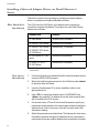
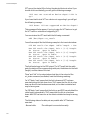
To run diagnostics, perform the following procedure:
Note
Diagnostics is a DOS based program and must be run in true DOS,
not in a DOS shell within Windows.
1.
If ON, power OFF your computer and reboot into DOS mode.
2.
At the DOS prompt and without the drivers loaded, type diag.exe.
The location of the diagnostic files on the CardAssistant CD are:
Adapter Card
Diagnostic Location
AT-2400 Series
\drivers\at2400\diag\diag24.exe
AT-2500, AT-2501 Series
\drivers\at2500\diag\diag25.exe
AT-2450, AT-2700,
AT-2701, AT-2745,
AT-2746 Series
\drivers\at24_27\diag\diag.exe
AT-2915, AT-2930 Series
\drivers\at29xx\diag\diag29.exe
For example, if you want to run diagnostics for an AT-2500 Series
adapater card and the CD is mapped to drive D, you would enter:
D:\drivers\at2500\diag\diag25.exe
If you are using a driver installation disk, the diagnostic files are
stored in the root directory on the disk.
For the
AT-2916T,
AT-2970, and
AT-2971 Series
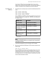
Diagnostics Program
The network adapter can be tested with the supplied diagnostics
program (running DOS). The diagnostics program run offline, for
example, normal operation of the network adapter can not be
maintained. During testing the link of the tested port will be down, for
examle, no data can be transferred. The following test are available:
❑ Simple test without loopback
This test covers all components but not the port (socket including
components for transmitting/receiving the data signals).
❑ Comprehensive port test with loopback
All components are tested, including the port.
24
Network Adapter Card Installation Guide - Book II
Note
The tests do not run in a Windows DOS box.
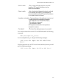
The location of the diagnostic file on the CardAssistant CD is:
Loopback Test
for Fiber
Adapters
Adapter Card
Driver Location
AT-2916T, AT-2970, AT-2971
Series
\drivers\at2971_16\diag\diagGE.exe
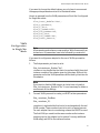
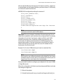
To perform the loopback test on fiber adapters, you will need a loopback
connector. Refer to Figure 5 below.
Figure 5 Setup for Loopback Testing
Be sure to observe the Translated Safety and Emission Information on
page 121.
To test the adapter, perform the following procedure:
1.
Power OFF your computer.
2.
If the computer is still connected to the network, unplug the data
cable from the network adapter’s port.
3.
Connect the network adapter as follows:
❑
For the simple test, insert the protective plugs into the ports.
❑
For the loopback test, insert the loopback connector into the
port.
4.
Boot to DOS. Wait until the operating system is loaded and the DOS
prompt is displayed.
5.
Insert the CardAssistant CD into the CD-ROM drive.
6.
Go to the product directory and type diagGE.
7.
Press <Enter>.
25
Diagnostics
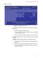
8.
From the Main Menu of the diagnostics program, select one of the
following:
❑
DIAGNOSTICS for the simple test (no loopback)
❑
LOOPB. WRAP PLUG for the loopback test
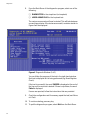
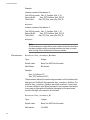
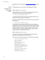
The various components will now be tested. This will take between
one and two minutes. If the test was successful, a window similar to
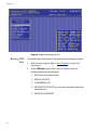
Figure 6 will be displayed.
Figure 6 Diagnostic Window (1 of 5)
You can follow the progress of the test in the right-hand window.
Each test is displayed as it is being performed (e.g. Board Register
Check).
If the test is successful, the word PASSED is displayed at the end of
the line and the next test is started. If there is a problem, the word
Failed is displayed.
If errors are reported, follow the instructions that are provided.
9.
Check the configuration and if necessary, repeat the test (see Failure
of a Test).
10. To continue testing, press any key.
11. To quit the diagnostics program, select Exit from the Main Menu.
26
Network Adapter Card Installation Guide - Book II
12. Remove the loopback connector from the port.
13. Re-connect the data cables to the network port.
Caution
For safety reasons, if the adapter is not connected immediately to
the data network, insert the protective plug. Otherwise laser light
may be emitted. Inserting the protective plug is also protects the
port against dust and dirt.
Repeater Test
for Copper
Adapters
For the AT-2916T, AT-2970, and AT-2971 Series adapters the test via
wrap plug is not available. However, loopback testing may be carried out
by connecting the adapter to another adapter installed in a second
computer running in repeater mode (further known as the repeater
computer). The computer in which the adapter is installed, which is to be
tested, is called test computer.
To test the copper adapter, perform the following procedure:
1.
Install a copper adapter in the repeater computer.
2.
Boot the repeater computer to DOS.
Wait until the operating system is loaded and the DOS prompt is
displayed.
3.
Insert the CardAssistant CD into the CD-ROM drive.
4.
Go to the product directory and type diagGE.
5.
Press <Enter>.
6.
From the Main Menu of the diagnostics program, select Repeater
Mode.
7.
Select the port which is to be tested, for example, A (for single link
adapters, only A is available).
8.
Press <Enter>.
The window Repeater Mode Port A is displayed.
9.
Install a copper adapter in the test computer.
10. Connect the adapter in the repeater computer to the adapter in the
test computer. Use a category 5 cable with RJ-45 plugs.
11. Boot the test computer to DOS.
Wait until the operating system is loaded and the DOS prompt is
displayed.
27
Diagnostics
12. Insert the CardAssitant CD into the CD-ROM drive.
13. Go to the product directory and type diagGE.
14. Press <Enter>.
15. From the Main Menu of the diagnostics program, select
LOOPB.WRAP PLUG.
16. Press <Enter>.
When the test was successful, the message All tests passed
successfully is dis-played.
When the test fails, the message failed is displayed. The further
procedure is described in section Failure of a Test.
17. Press any key to continue.
18. On the test computer, select Exit to quit the diagnostics program.
19. On the repeater computer, select Exit to quit the diagnostics
program.
28
Network Adapter Card Installation Guide - Book II
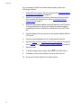
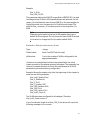
Failure of a Test
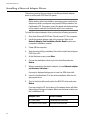
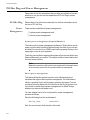
Figure 7 Diagonstic Window (2 of 5)
For a test to be completed successfully, each of the following conditions
must be met:
❑ The network adapter operates correctly.
❑ The network adapter is cabled correctly for the test or is equipped
with the correct connectors.
❑ The network adapter has been installed correctly in the computer.
The failed message does not necessarily imply that the network adapter
is faulty.
If a failed message is displayed, perform the following procedure:
1.
Follow the instructions that are displayed in the window below the
list of tests.
2.
Make sure that the adapter is inserted correctly and the ports are
connected properly (connectors are firmly seated, the correct end of
the cable is connected).
29
Diagnostics
If it is necessary to install the network adapter again, perform the
following procedure:
1.
Switch OFF the computer. Be sure to observe the Translated Safety
and Emission Information on page 121.
2.
Remove the computer cover. Refer to the manual that came with
your computer for instructions or refer to Installing a Network
Adapter Card on page 17.
3.
Make sure the network adapter is properly seated in the PCI bus slot
on the motherboard. If not, do not remove the network adapter
completely but raise it sufficiently to withdraw it from the PCI bus
slot.
4.
Carefully realign the bus connector on the network adapter with the
PCI bus slot.
5.
Press the network adapter until it is firmly seated in the slot.
6.
Repeat to Step 6 of the Loopback Test for Fiber Adapters on page 25
and to Step 4 of the Repeater Test for Copper Adapters on page 27.
7.
Repeat the test.
8.
To quit the diagnostics program, select EXIT in the Main Menu.
9.
If necessary, remove the loopback connector from the port.
10. Re-connect the data cables to the network ports.
30
Network Adapter Card Installation Guide - Book II
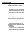
Additional Functions of the Diagnostics Program
Checking Other
Displays and
Data
In addition to performing the three network adapter tests, the
diagnostics program can also read out network adapter-specific data
that may be useful for pinpointing the causes of failure.
You can:
❑ read sensor data
❑ read configuration data
❑ read and write VPD data
❑ read and write Flash EPROM data
Main Program
To start the main program, proceed as follows:
1.
Boot to DOS and wait for the prompt.
2.
Insert the installation CD-ROM into the CD-ROM drive of the
computer in which the network adapter is installed.
3.
Type the letter of your CD-ROM drive (for example, D:)
4.
Go to the appropriate product directory and type diagGE.
5.
Press <Enter>.
31
Diagnostics
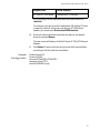
The Main Menu as shown in Figure 8 is displayed:
Figure 8 Diagnostic Window (3 of 5)
6.
Select the appropriate item from the menu.
7.
To quit the program, select EXIT in the Main Menu.
This option is automatically offered for selection if you did not select
a menu item previously.
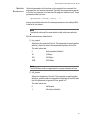
Reading Sensor
Data
To read sensor data, perform the following procedure:
1.
Start the main program. Refer to Main Program on page 31 for
instructions.
2.
Select Show Sensors in the Main Menu. A separate window will be
displayed for the following sensor data:
❑
Temperature of the board
❑
Voltage on the PCI card
❑
Voltage on the PCI I/O lines
❑
Other supply voltages
In the Main Menu, Show Sensors changes to Hide Sensors.
32
Network Adapter Card Installation Guide - Book II
3.
You can close the window by selecting Hide Sensors from the Main
Menu.
Other windows may be opened while this window is still open, for
example, the window displaying the configuration data.
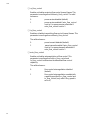
Reading
Configuration
Data
To read configuration data, perform the following procedure:
1.
Start the main program. Refer to Main Program on page 31 for
instructions.
2.
Select SHOW CONFIGURATION in the main menu. A separate
window will be displayed showing:
❑
Device code (Device)
❑
Various vendor codes (Vendor)
❑
Interrupt no. (IRQ)
❑
Cache Line Size (CLS)
❑
Latency (Lat.)
❑
RAM size (RAM)
❑
PCI slot index and size (Slot and Slot size)
❑
PCI bus clock (clk)
❑
MAC address (MAC Addr)
❑
Port type (PMD-Type)
❑
Connector (connector)
❑
Hardware revision (HW Rev)
❑
Chip ID (Chip Id)
In the Main Menu, Show Configuration changes to Hide
Configuration.
3.
You can close the window by selecting Hide Configuration from
the Main Menu.
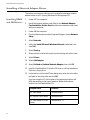
Other windows may be displayed while this window is still open,for
example, a window shown in Figure 9 will be displayed.
33
Diagnostics
Figure 9 Diagnostic Window (4 of 5)
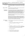
Reading VPD
Data
34
To read VPD data (Vital Product Data), perform the following procedure:
1.
Start the main program. Refer to Main Program on page 31 for
instructions.
2.
Select VPD Data from the Main Menu. A submenu with the
following options will be displayed:
❑
EXIT (return to the Main Menu)
❑
DISPLAY VPD DATA
❑
CLEAR ERROR LOGS
❑
ADD/MODIFY VPD DATA (you can enter user-defined data and
keywords here)
❑
DELETE VPD KEYWORDS
Network Adapter Card Installation Guide - Book II
Figure 10 Diagnostic Window (5 of 5)
3.
Select the desired option or return to the Main Menu by selecting
Exit (default option).
35
Chapter 3
Microsoft DOS Client 3.0
This chapter contains the following procedures for the AT-24xx, AT-25xx,
and AT-2700 Series adapters:
❑ Installing a Network Adapter Driver on page 38
❑ Removing a Network Adapter Driver on page 40
37
Microsoft DOS Client 3.0
Installing a Network Adapter Driver
This section contains the procedure for installing a network adapter
driver on a Microsoft DOS Client 3.0 system.
Note
Before starting with the installation procedure, make sure that the
adapter is properly configured using setup25.EXE provided on the
CardAssistant CD. If necessary, match the speed and duplex settings
of the network card with the hub with which it is connected.
To install the network adapter driver, perform the following procedure:
1.
Shut down Microsoft DOS Client 3.0 and power OFF the computer.
2.
Install the network adapter card in the compute. Refer to the
Network Adapter Card Installation Guide - Book I and to your
computer’s installation manual.
3.
Power ON the computer.
4.
Start the setup utility provided by Microsoft to install and configure
DOS Client v3.0.
5.
At the Welcome screen, press Enter.
6.
Choose the destination directory for the client files and press
Return.
7.
When prompted for the network adapter, choose Network adapter
not shown on list below . . .
A prompt is displayed asking you to insert the OEM driver disk.
8.
Insert the CardAssistant CD or the driver installation disk into the
appropriate drive.
9.
Type in the driver letter and path to the NDIS 2.0 driver and press
Return.
If you are using the CD, the location of the adapter driver will differ
depending on the type of adapter. Below are the driver locations on
the CardAssistant CD:
Adapter Card
Driver Location
AT-2400 Series
\drivers\at2400\msclient
AT-2500/AT-2501 Series
38
\drivers\at2500\msclient
Network Adapter Card Installation Guide - Book II
Adapter Card
Driver Location
AT-2450, AT-2700 Series
\drivers\at24_27\msclient
If you are using a driver installation disk, the driver location is:
\msclient.
For example, if you are using the CardAssistant CD and the CD driver
is mapped to drive D and you are installing an AT-2500 Series
adapter, you would enter D:\drivers\at2500\msclient.
10. Once you have entered the drive letter and path to the adapter
driver and pressed Return.
The next screen will display the Allied Telesyn AT-250x PCI Ethernet
Adapter.
11. Press Return to select the driver and proceed with the installation
according to the Microsoft documentation.
Sample
Configuration
[network.setup25]
version=0x3110
netcard=ATI$a2500,1,ATI$a2500,1
transport=tcpip,TCPIP
lana0=ATI$a2500,1,tcpip
39
Microsoft DOS Client 3.0
Removing a Network Adapter Driver
This section contains the procedure for removing an adapter driver from
a system running Microsoft Client 3.0.
To remove an adapter driver, perform the following procedure:
40
1.
Start the Microsoft setup utility.
2.
Select Change Network Configuration.
3.
Select the network adapter whose driver you want removed from
the system.
4.
Click Remove.
Chapter 4
Microsoft Windows for
Workgroups
This chapter contains procedures the following procedures for the
AT-24xx, AT-25xx, AT-2700 Series adapters:
❑ Installing a Network Adapter Driver on page 42
❑ Removing a Network Adapter Driver on page 48
41
Microsoft Windows for Workgroups
Installing a Network Adapter Driver
This section contains the instructions for manually installing a network
adapter driver on a PC running Windows for Workgroups 3.11.
Installing NDIS2
and ODI Drivers
1.
Power OFF the computer.
2.
Install the network adapter card. Refer to the Network Adapter
Card Installation Guide - Book I and the documentation that came
with your computer.
3.
Power ON the computer.
4.
From the Network group under Program Manager, choose Network
Setup.
5.
Select Networks.
6.
Verify that Install Microsoft Windows Network is selected, then
select OK.
7.
Select Sharing.
8.
Select whether to allow file and/or printer sharing with other users.
9.
Select Drivers.
10. Select Add Adapter.
11. Select Unlisted or Updated Network Adapter, then click OK.
12. Insert the CardAssistant CD into the CD drive or a Driver Installation
Disk into a floppy drive.
13. In the text box of the Install Driver dialog box, enter the drive letter
and path to the driver files and click OK.
If you are using the CD, the location of the appropriate driver will
differ depending on the type of adapter. Below are the driver
locations on the CardAssistant CD:
42
Adapter Card
Location
AT-2400 Series
\drivers\at2400
AT-2500/AT-2501 Series
\drivers\at2500
AT-245x Series, AT-27xx
Series
\drivers\at24_27
Network Adapter Card Installation Guide - Book II
If you are using a Driver Installation Disk, the driver location is the
root (\) directory.
14. In the Network Adapters list of the Unlisted or Updated Network
Adapter dialog box, verify that Allied Telesyn PCI Ethernet
Adapter is highlighted, then click OK.
15. In the Network Drivers dialog box, verify that Allied Telesyn PCI
Ethernet Adapter and its default protocols, Microsoft NetBEUI and
IPX/SPX Compatible Transport with NetBIOS, appear in the Network
Drivers list, then click Close.
16. In the Network Setup dialog box, click OK.
17. If prompted, insert the required Windows for Workgroups
diskette(s) into your floppy drive and click OK.
Note
Windows for Workgroups occasionally loses its place at this point; if
you get a message from Windows that it cannot find a file, try
inserting Windows for Workgroups installation diskettes 7 and 8.
18. If prompted, reinsert the CardAssistant CD or Driver Installation Disk
into the appropriate drive.
19. In the text box of the Install Driver dialog box, click OK.
20. From the Windows Setup dialog box, select Restart Computer.
43
Microsoft Windows for Workgroups
AT-245x,
AT-27xx NDIS2
Keywords
The AT-245x and AT-27xx series NDIS2 driver supports the following
options:
❑ 0 = auto
❑ 1 = 100H
❑ 2 = 100F
❑ 3 = 10H
❑ 4 = 10F
❑ 5 = hardware
Sample
PROTOCOL.INI
File
[network.setup]
version=0x3110
netcard=ms$a2500,1,MS$a2500,3
transport=ms$nwlinknb,NWLINK
transport=ms$ndishlp,MS$NDISHLP
transport=ms$netbeui,NETBEUI
lana0=ms$a2500,1,ms$netbeui
lana1=ms$a2500,1,ms$nwlinknb
lana2=ms$a2500,1,ms$ndishlp
[protman]
DriverName=PROTMAN$
PRIORITY=MS$NDISHLP
[NWLINK]
BINDINGS=MS$a2500
[MS$NDISHLP]
DriverName=ndishlp$
BINDINGS=MS$a2500
[NETBEUI]
DriverName=netbeui$
SESSIONS=10
NCBS=12
BINDINGS=MS$a2500
LANABASE=0
[MS$a2500]
DriverName=a2500$
[a2500]
Adapters=MS$a2500
44
Network Adapter Card Installation Guide - Book II
Note
These are the default values for installation. If you are adding any
TCP/IP software, this configuration will satisfy the NDIS 2.0
requirements of TCP/IP systems.
NetWareIPXODI
Support for
NetWare 3.x
1.
Create a new directory on your local hard drive (e.g.; C:\ATINET).
2.
Copy the contents of the DOSODI directory on the CardAssistant CD
or the Driver Installation Disk to the directory you created.
If you are using the CardAssistant CD, the location of the
appropriate driver will differ depending on the type of adapter.
Below are the driver locations on the CardAssistant CD:
Adapter Card
Location
AT-2400 Series
\drivers\at2400\Dosodi
AT-2500/AT-2501 Series
\drivers\at2500\Dosodi
AT-2450 Series, AT-2700
Series
\drivers\at24_27\Dosodi
If you are using a driver installation diskette, the driver location is
\Dosodi.
3.
Verify that the ODI drivers for the AT-2500/AT-2501 Ethernet
Adapter Card are NOT loaded before setting up Windows for
Workgroups.
4.
Start Windows.
5.
Choose Network Setup from the Network group.
6.
Select Networks.
7.
Select Install Microsoft Windows Network, then Other.
8.
Select Novell NetWare (Workstation Shell 3.X), then OK.
9.
Select IPXODI.COM and LSL.COM (recommended), then OK.
10. Verify that ATI AT-xxxx[ODI/NDIS2] and its default protocols,
Microsoft NetBEUI and IPX/SPX Compatible Transport with
NetBIOS, appear in the Network Drivers list, then OK.
11. When asked if you want to modify the net.cfg file, you can enter the
path to the directory created earlier for your ODI files (for example,
C:\ATINET). After you make your changes, or if you do not want to
make changes, click OK.
45
Microsoft Windows for Workgroups
12. From the Windows Setup dialog box, select Continue.
13. Edit the Autoexec.bat file by inserting the following file references
before C:\WINDOWS\odihlp.exe:
c:\ net\lsl
c:\net\a2500 (atnic,a2400)
c:\net\ipxodi
c:\net\netx
14. Exit Windows and re-boot your PC by powering OFF then ON.
NetWare
IPXODI Support
For NetWare 4.x
1.
Verify that the ODI drivers for the AT-2500/AT-2501 Ethernet
Adapter Card are NOT loaded before setting up Windows for
Workgroups.
2.
From the DOS command line, install the NetWare DOS/Windows
Client software. Select Yes to install Windows support and then
enter the path to your Windows directory, for example,
C:\WINDOWS
3.
Start Windows.
4.
Select Network Setup from the Network group.
5.
select Networks.
6.
Select Install Microsoft Windows Network, then select Other.
7.
From the Other drop down list, select Novell NetWare
(Workstation Shell 4.0 and above) and click OK.
8.
Select IPXODI.COM and LSL.COM (recommended), then OK.
9.
In the Network Drivers dialog box, verify that ATI AT-xxxx
[ODI/NDIS2] and its default protocols, Microsoft NetBEUI and
IPX/SPX Compatible Transport with NetBIOS, appear in the
Network Drivers lis and then click OK.
10. From the Windows Setup dialog box, select Restart Computer.
Installing Novell NetWare 3.x and 4.x support adds
DEVICE=C:\WINDOWS\IFSHLP.SYS to your CONFIG.SYS file
and C:\WINDOWS\ODIHLP.EXE to your AUTOEXEC.BAT file.
Note
The sample AUTOEXEC.BAT shows VLM.EXE being used instead of
NETX.EXE. VLMs are required for NetWare 4.x but may be an
alternative to NETX with NetWare 2.x and 3.x.
46
Network Adapter Card Installation Guide - Book II
Sample
NET.CFG and
PROTOCOL.INI
Files
NET.CFG
Preferred Server = MyServer
Link Driver a2500
LineSpeed 100F (optional)
Frame Ethernet_802.3
Frame Ethernet_II
Frame Ethernet_802.2
Frame Ethernet_SNAP
VLM Support
NETWARE DOS REQUESTER
FIRST NETWORK DRIVE=F
PROTOCOL.INI
[network.setup]
version=0x3110
netcard=ms$a2500,1,MS$a2500,4
transport=ms$netbeui,NETBEUI
transport=ms$nwlinknb,NWLINK
lana0=ms$a2500,1,ms$nwlinknb
lana1=ms$a2500,1,ms$netbeui
[MS$a2500]
[NETBEUI]
BINDINGS=a2500
LANABASE=1
[net.cfg]
PATH=C:\NET\net.cfg
[Link Driver a2500]
data=Frame Ethernet_SNAP
data=Frame Ethernet_802.2
data=Frame Ethernet_II
data=Frame Ethernet_802.3
data=Link Driver a2500
[NWLINK]
BINDINGS=a2500
47
Microsoft Windows for Workgroups
Removing a Network Adapter Driver
This section contains the procedure for removing a network adapter
driver from a system running Microsoft Windows for Workgroups 3.11.
The initial installation copies the OEMSETUP.INF to your
WINDOWS\SYSTEM directory. It renames the file to OEMx.INF, where x is
a number starting with 0 for drivers that are not shipped with Windows
for Workgroups; this also pertains to video and printer drivers.
48
1.
Click the Network Icon in the Network Control panel.
2.
Select the Drivers button in Network Setup.
3.
Select the Remove button.
4.
Select Yes when asked if you want to remove the driver.
Chapter 5
Novell Netware
This chapter contains the following procedures:
❑ Installing a Network Adapter Driver on Novell Netware 4 Server on
page 50
❑ Installing a Network Adapter Driver on Novell NetWare 5.x/6.x on
page 55
49
Novell Netware
Installing a Network Adapter Driver on Novell Netware 4
Server
This section contains the procedure for installing a network adapter
driver on a system running Novell NetWare 4 Server.
Files Needed for
Installation
The .LDI file and the .LAN file for your adapter must be present to
succesfully complete installation. The location for each Allied Telesyn
adapter are as follows:
Adapter Card
Location
AT-2400 Series
\drivers\at2400\netware\
AT-2500/AT-2501 Series
\drivers\at2500\netware\
AT-2450/AT-2451 Series,
AT-2700/AT-2701 Series,
AT-2746 Series
\drivers\at24_27\netware\
AT-2915 Series, AT-2930
Series
\drivers\at29xx\netware\
AT-2916T, AT-2970,
AT-2971 Series
\drivers\at2971\netware\1
1. For additional AT-2916T, AT-2970, and AT-2971 parameter information, refer to the
AT297x.txt file.
New Server
Installation
50
1.
Follow the directions provided by Novell to load the network drivers
using the INSTALL.NLM program.
2.
When the Install program prompts for the LAN driver, select Insert
to specify a driver not listed.
3.
Insert the CardAssistant CD or driver installation disk into the
appropriate drive.
4.
Press <F3> to change the default path to A:\NETWARE. Press
<Enter> as prompted. The adapter driver and other required files
will be copied to the SYS: volume.
5.
On the next menu, AT-2xxx Protocols and Parameters, specify any
parameters where needed. A slot value is required when loading the
adapter driver. If slot is unknown, driver will correctly detect slot
value when loading.
6.
Select Save parameters and load driver. The Netware 4.x driver has a
PermaNet parameter that gives the Netware Server a redundancy
mechanism where two network adapters are connected to the same
Network Adapter Card Installation Guide - Book II
local network. When the primary adapter fails, the secondary
adapter then handles the network traffic until the primary adapter is
restored. Proceed with the installation as outlined by Novell.
Installing the
Drivers
1.
At the file server console prompt, issue the load statement(s) in this
order:
LOAD
LOAD
LOAD
LOAD
<DRIVE>:<PATH>\NBI
<DRIVE>:<PATH>\MSM
<DRIVE>:<PATH>\ETHERTSM
<DRIVE>:<PATH>\<DRIVER>
where <DRIVE> and <PATH> are the drive and directory where you
copied the NLMs and the adapter file. <DRIVER> is the filename of
the adapter driver.
Adapter Card
Location
AT-2400 Series
\drivers\at2400\netware\
AT-2500/AT-2501 Series
\drivers\at2500\netware\
AT-2450/AT-2451 Series,
AT-2700/AT-2701 Series,
AT-2746 Series
\drivers\at24_27\netware\
AT-2915 Series, AT-2930
Series
\drivers\at29xx\netware\
AT-2916T, AT-2970,
AT-2971 Series
\drivers\at2971_16\netware\1
1. For additional AT-2916T, AT-2970, and AT-2971 parameter information, refer to the
AT297x.txt file.
Note
If MSM and ETHERTSM NLMs are not loaded, they'll automatically
load before the driver.
You will be prompted if you do not specify a SLOT number.
2.
Next you must bind the LAN driver to IPX in order to attach to the
server. Type:
BIND IPX TO <DRIVER> NET=n
Where <DRIVER> is the filename of the adapter driver and n is the
node address Novell uses for routing IPX packets. This number is
arbitrary if there is the only one server on the network, but if there
are multiple servers on the same network, it must match the other
servers' external network number.
51
Novell Netware
Note
The default frame type for Novell file servers is now Ethernet_802.2.
If you require Ethernet_802.3, specify FRAME=ETHERNET_802.3 on
the command line when loading the driver.
To load multiple frame types for a single card, enter a LOAD and
BIND statement for each frame type. You need to supply a name on
each load line in order to avoid being prompted for which board to
bind IPX to. If you do not have the name option in the
AUTOEXEC.NCF, it will not execute completely without user
intervention.
Example:
LOAD
BIND
LOAD
BIND
<DRIVER> FRAME=ETHERNET_802.3 NAME=IEE8023
IPX TO IEE8023 NET=11111
<DRIVER> FRAME=ETHERNET_802.2 NAME=IEE8022
IPX TO LAN8022 NET=22222
Where <DRIVER> is the filename of the adapter driver.
Additionally, if you have a PCI-1 bus in your system, add
BUSTYPE=PCI1 to the command line, for example, LOAD
C:\SERVER.4\<driver> BUSTYPE=PCI1. Otherwise the driver
may not find the card. If you don't know which bus you have, try
loading without the option. If it loads, you do not need it.
3.
Add the load and bind statements you require to the server's
AUTOEXEC.NCF file so that the LAN driver will load automatically
each time the server starts up.
Here's an example of how the commands would look in your
AUTOEXEC.NCF file.
Example:
LOAD a2500v3 FRAME=Ethernet_802.3 (overrides
default frame BIND IPX to a2500v3 net=1 (all servers
on the LAN segment need the same #)
4.
52
Proceed with the installation as outlined by Novell.
Network Adapter Card Installation Guide - Book II
Multiple
Adapters
If a system has multiple Allied Telesyn Ethernet Adapters, you use the
keyword SLOT to identify each card to the driver. If you have multiple
adapters in a single server, each adapter must have a different network
number and SLOT number. Also, you might want to name each adapter.
So add the options in LOAD commands to distinguish particular
adapters. For example:
LOAD
BIND
LOAD
BIND
<DRIVER> FRAME=Ethernet_802.2 NAME=LAN_A SLOT=1
IPX TO LAN_A NET=11
<DRIVER> FRAME=Ethernet_802.2 NAME=LAN_B SLOT=2
IPX TO LAN_B NET=22
<DRIVER> is the filename of the adapter driver.
Add the load and bind statements you need to the server's
AUTOEXEC.NCF file so that the Allied Telesyn adapter drivers load
automatically each time the server starts.
In an IPX internal router configuration (a server with two adapters, each
connected to a different network), the data transfer rate across the
router can be low. This happens if client workstations have CPU speeds
equal to or higher than the server. You might be able to increase the
data transfer rate by adding the following line to STARTUP.NCF:
SET MAXIMUM INTERRUPT EVENTS = 100000
The default setting is 10.
If you have problems loading the driver on multiple adapters and the
initialization fails due to "Insufficient RCBs," increase the number of
buffers allocated to the server. Add the following to STARTUP.NCF:
SET MINIMUM PACKET RECEIVE BUFFERS = 100 (or larger)
SET MAXIMUM PACKET RECEIVE BUFFERS = 500 (or larger)
The MINIMUM value you specify must be at least 30 times the number of
Allied Telesyn PCI adapters in the computer.
Recommended settings:
1-3 adapters: 100
4 adapters: 150
The maximum you can specify depends on the amount of memory in
the server, but it must be greater than the minimum.
53
Novell Netware
Removing an
Adapter Driver
from Novell
Netware 4
Server
54
This section contains the procedure for removing a network adapter
driver from a system running Novell Netware 4 Server.
1.
Type LOAD INSTALL at the server console to bring up the server
installation module.
2.
Select Driver Options and press Return.
3.
Select Deselect a selected driver from the next menu and press
Return. The highlight is moved to the installed adapter(s).
4.
Press Return again to remove the selected driver.
Network Adapter Card Installation Guide - Book II
Installing a Network Adapter Driver on Novell NetWare
5.x/6.x
This section contains the procedure for installing a network adapter
driver on a system running Novell NetWare 5.x/6.x.
Files Needed for
Installation
The .LDI file and the .LAN file for your adapter must be present to
succesfully complete installation. The location for each Allied Telesyn
adapter are as follows:
Adapter Card
Location
AT-2400 Series
\drivers\at2400\netware\
AT-2500/AT-2501 Series
\drivers\at2500\netware\
AT-2450/AT-2451 Series,
AT-2700/AT-2701 Series,
AT-2745/AT-2746 Series,
\drivers\at24_27\netware\
AT-2915 Series, AT-2930
Series
\drivers\at29xx\netware\
AT-2916T, AT-2970,
AT-2971 Series
drivers\at2971_16\netware\1
1. For additional AT-2916T, AT-2970, and AT-2971 parameter information, refer to the
AT297x.txt file.
New Server
Installation
The NetWare 5 utility NWCONFIG provides the user with the abitlity to
add additional network adapter cards. At the system console, type
NWCONFIG.
1.
Select Driver Options then Configure Network Driver.
2.
Select an Additional Driver.
The NWCONFIG displays a list of the available drivers.
3.
Press <Insert> to specify a driver not listed.
4.
Insert the CardAssistant CD or the Driver Installation Disk into the
appropriate drive.
55
Novell Netware
If you are using the CardAssistant CD, the names and locations of the
adapter drivers are as follows:
Adapter Card
Location
AT-2400 Series
\drivers\at2400\netware\
AT-2500/AT-2501 Series
\drivers\at2500\netware\
AT-2450/AT-2451 Series,
AT-2700/AT-2701 Series,
AT-2745/AT-2746 Series,
\drivers\at24_27\netware\
AT-2915 Series, AT-2930
Series
\drivers\at29xx\netware\
AT-2916T, AT-2970,
AT-2971 Series
drivers\at2971_16\netware\1
1. For additional AT-2916T, AT-2970 and AT-2971 parameter information, refer to the
AT297x.txt
file.
If you are using a Driver Installation Disk, the adapter driver will be
located in the root directory.
5.
Press <F3> to change the default path.
6.
Press Return.
The adapter driver and other required files are copied to the SYS:
volume.
Manual
Installation
7.
On the next menu, Protocols and Parameters, specify any
parameters where needed. A slot value is required when loading the
adapter driver. If the slot is unknown, driver will correctly detect slot
value when loading.
8.
Select Save parameters and load driver.
9.
Proceed with the installation as outlined in the Novell
documentation.
1.
At the file server console prompt, issue the load statement(s) in this
order:
LOAD
LOAD
LOAD
LOAD
56
<DRIVE>:<PATH>\NBI
<DRIVE>:<PATH>\MSM
<DRIVE>:<PATH>\ETHERTSM
<DRIVE>:<PATH>\<DRIVER>
Network Adapter Card Installation Guide - Book II
Where <DRIVE> and <PATH> are the drive and directory where you
copied the NLMs and the adapter driver file. <DRIVER> is the
filename of the driver.
Note
If MSM and ETHERTSM NLMs are not loaded, they will automatically
load before the driver. You will be prompted if you do not specify a
SLOT number.
Type the following command to bind the LAN driver to IPX in order
to attach to the server.
BIND IPX TO <DRIVER> NET=n
Where <DRIVER> is the filename of the driver and n is the node
address Novell uses for routing IPX packets. This number is arbitrary
if there is the only one server on the network, but if there are
multiple servers on the same network, it must match the other
servers' external network number.
Note
The default frame type for Novell file servers is now Ethernet_802.2.
If you require Ethernet_802.3, specify FRAME=ETHERNET_802.3 on
the command line when loading the driver.
To load multiple frame types for a single card, enter a LOAD and
BIND statement for each frame type. You need to supply a name on
each load line in order to avoid being prompted for which board to
bind IPX to. If you do not have the name option in the
AUTOEXEC.NCF, it will not execute completely without user
intervention.
Example:
LOAD
BIND
LOAD
BIND
<DRIVER> FRAME=ETHERNET_802.3 NAME=IEE8023
IPX TO IEE8023 NET=11111
<DRIVER> FRAME=ETHERNET_802.2 NAME=IEE8022
IPX TO LAN8022 NET=22222
<DRIVER> is the filename of the adapter driver.
If you have a PCI-1 bus in your system, add BUSTYPE=PCI1 to the
command line (for example, LOAD C:\SERVER\A2500v3
BUSTYPE=PCI1). Otherwise the driver may not find the card. If you
don't know which bus you have, try loading without the option. If it
loads, you don't need it.
57
Novell Netware
Add the load and bind statements you require to the server's
AUTOEXEC.NCF file so that the LAN driver will load automatically
each time the server starts up. Here's an example of how the
commands would look in your AUTOEXEC.NCF file.
("NCF Files Options - Create / Edit Server Startup
Files")
LOAD A2500v3 FRAME=Ethernet_802.3 (overrides
default frame type)
BIND IPX to A2500v3 net=1 (all servers on the LAN
segment need the same #)
2.
Multiple
Adapters
Proceed with the installation as outlined by Novell.
If you have multiple Allied Telesyn adapters installed in the system, use
the keyword SLOT to identify each card to the driver. If you have
multiple adapters in a single server, each adapter must have a different
network number and SLOT number. Also, you might want to name each
adapter. So add the options in LOAD commands to distinguish particular
cards. For example:
LOAD
BIND
LOAD
BIND
A2500v3 FRAME=Ethernet_802.2 NAME=LAN_A SLOT=1
IPX TO LAN_A NET=11
A2500v3 FRAME=Ethernet_802.2 NAME=LAN_B SLOT=2
IPX TO LAN_B NET=22
Add the load and bind statements you need to the server's
AUTOEXEC.NCF file so that the adapter drivers load automatically each
time the server starts.
In an IPX internal router configuration (a server with two adapters, each
connected to a different network), the data transfer rate across the
router can be low. This happens if client workstations have CPU speeds
equal to or higher than the server. You might be able to increase the
data transfer rate by adding the following line to STARTUP.NCF:
SET MAXIMUM INTERRUPT EVENTS = 100000
The default setting is 10.
If you have problems loading the driver on multiple adapters and the
initialization fails due to "Insufficient RCBs," increase the number of
buffers allocated to the server. Add the following to STARTUP.NCF:
SET MINIMUM PACKET RECEIVE BUFFERS = 100 (or larger)
SET MAXIMUM PACKET RECEIVE BUFFERS = 500 (or larger)
The minimum value you specify must be at least 30 times the number of
PCI adapters in the computer.
Recommended settings:
58
Network Adapter Card Installation Guide - Book II
1-3 adapters: 100
4 adapters: 150
The maximum you can specify depends on the amount of memory in
the server, but it must be greater than the minimum.
59
Novell Netware
Removing an
Adapter Driver
from Novell
Netware 5/6
Server
60
This section contains the procedure for removing a network adapter
driver from a system running Novell Netware 5 or Netware 6 Server.
To remove a driver, you can either use the NWCONFIG program supplied
with NetWare or edit the AUTOEXEC.NCF in the SYS:SYSTEM directory
with a text editor. The procedure below explains how to remove a driver
using the NWCONFIG program.
1.
Type NWCONFIG at the server console to bring up the installation
module.
2.
Select Driver Options and press Return.
3.
Select Deselect a selected driver from the next menu and press
Return. This moves the highlight to the installed adapter(s).
4.
Selct the adapter you wish to remove.
5.
Press Return again to remove the selected driver.
Chapter 6
Linux
This chapter contains the following procedures:
❑ Installing the ATNIC Driver for AT-2450/AT-2451, AT-2700/
AT-2701 Series, and AT-2745/AT-2746 Series PCI Ethernet
Adapters on page 62
❑ Installing a Linux Driver for an AT-2915 and AT-2930 Series
Network Adapter on page 64
❑ Installing Linux Driver on a AT-2916T, AT-2970, or AT-2971 Series
Adapters on page 67
61
Linux
Installing the ATNIC Driver for AT-2450/AT-2451, AT-2700/
AT-2701 Series, and AT-2745/AT-2746 Series PCI Ethernet
Adapters
This driver supports dynamic loading and unloading via the KLM
support provided by Linux. As a result, you must custom build the driver
for the particular version of the kernel installed. The driver is located on
CardAssistant at/drivers/at2701/linux.
Limitations
The current version of the driver has been tested as a loadable module
on Red Hat 7.0, 7.1, and 7.2 Linux distributions for i386 and ia64. Testing
has also been done on other similar Linux distributions using the 2.4.x
kernels.
Note
You must have the kernel source code and the the full GCC library
installed in order to build and load the driver. For RedHat, the kernel
source is located on the installation CDs (Disk2), not the source CDs.
Look for a file with the name KERNEL-SOURCE-X.X.XX-i386.RPM,
where x stands for build number.
Building the
Driver
To insure that the kernel source code is installed, change to the
USR/SRC directory and verify that the linux source tree is present.
Look for linux-x.x.x-x, where x stands for the current build numbers.
If you only see a linux directory, chances are you've got the wrong
source files installed.
Installing the
Driver
62
1.
Copy the Allied Telesyn driver source TAR file to a temporary
directory, and type tar -xvf <filename> to extract the files.
2.
Edit Makefile using VI or your favorite text editor, and change the
LINUX path variable to the directory name where the kernel source
files are installed.
3.
Type make to compile the driver source code. You should see the
atnic32.o file is created if successfull.
4.
Continue with driver installation.
Run make install to install the driver.
The atnic32.o file will be copied to the
lib/modules/<build#>/kernel/drivers/net directory and depmod - a will
be run to update dependancies.
Network Adapter Card Installation Guide - Book II
Dynamic
Loading
Type insmod atnic32.o to dynamically load the driver without installing
it into the operating system.
To configure network protocol and address, refer to Linux
documentations.
Changing
Configuration
Settings
To enable Autonegotiation edit the /etc/conf.modules file to add the
line options atnic options=0 below the alias eth0 atnic
line. The following indicate the various options for enabling the various
interfaces. Only ONE of the following lines can be added. Only one
interface is activated based on the keyword it represents. If neither
option is selected the driver/device defaults to autonegotiation. Each
option is selected by the number it represents.
Note
Full duplex ooperation on the Am79C970 chipset-based cards is
only supported on the 10Base-T interface.
AT-2450F, AT-2450FTX, AT-2700TX, AT-2700FX, AT-2745FX,
AT-2700FTX (AMD Am79C972 - Fast+ chipset):
options atnic options=0 #(MII, Autonegotiation)
options atnic options=1 #(MII, 100Mbps, Half duplex)
options atnic options=2 #(MII, 100Mbps, Full duplex)
options atnic options=3 #(MII, 10Mbps, Half duplex)
options atnic options=4 #(MII, 10Mbps, Full duplex)
AT-2450T/BT/AT/FT (AMD Am79C970 chipset):
options atnic options=5#(Auto Port Selection)
options atnic options=6#(Fiber/BNC/AUI)
options atnic options=7#(10baseT, Half duplex)
options atnic options=8#(10baseT, Full duplex)2450FT/T/BT/AT
For example:
alias eth0 atnic
options atnic options=3
63
Linux
Installing a Linux Driver for an AT-2915 and AT-2930 Series
Network Adapter
This driver supports dynamic loading and unloading via the KLM
support provided by Linux. As a result, you must custom build the driver
for the particular version of the kernel installed. The driver is located on
CardAssistant at/drivers/at29xx/linux.
Limitations
The current version of the driver has been tested as a loadable module
on Red Hat 7.0, 7.1, and 7.2 Linux distributions for i386 and ia64. Testing
has also been done on other similar Linux distributions using the 2.4.x
Note
You must have the kernel source code and the the full GCC library
installed in order to build and load the driver. For RedHat, the kernel
source is located on the installation CDs (Disk2), not the source CDs.
Look for a file with the name KERNEL-SOURCE-X.X.XX-i386.RPM,
where x stands for build number.
Building the
Driver
To insure that the kernel source code is installed, change to the
USR/SRC directory and verify that the linux source tree is present.
Look for linux-x.x.x-x, where x stands for the current build numbers.
If you only see a linux directory, chances are you've got the wrong
source files installed.
Installing the
Driver
Dynamic
Loading
1.
Copy the Allied Telesyn driver source TAR file to a temporary
directory, and type tar -xvf <filename> to extract the files.
2.
Edit Makefile using VI or your favorite text editor, and change the
LINUX path variable to the directory name where the kernel source
files are installed.
3.
Type make to compile the driver source code. You should see the
at29xx.o file is created if successfull.
4.
Continue with driver installation.
Run make install to install the driver.
The at29xx.o file will be copied to the
lib/modules/<build#>/kernel/drivers/net directory and depmod - a will
be run to update dependancies.
Type insmod at29xx.o to dynamically load the driver without installing
it into the operating system.
To configure network protocol and address, refer to Linux
documentations.
64
Network Adapter Card Installation Guide - Book II
Module
Parameters
Optional parameters for the driver can be supplied as command line
arguments to the insmod command. Typically, these parameters are set
in the file /etc/modules.conf (see the man page for modules.conf). These
parameters take the form:
<parameter>=value[,value,...]
where the multiple values for the same parameter are for multiple NICs
installed in the system.
Note
The default values will be used when invalid values are selected.
All the parameters are listed below.
❑ line_speed
Selects the line speed of the link. This parameter is used together
with full_duplex to select the speed and duplexity of the link.
The valid values are:
0
Autonegotiate (default)
10
10 Mbps
100
100 Mbps
1000
1000 Mbps
Note
The 1000 Mbps must be negotiated for copper twisted pair links.
❑ full_duplex
Selects the duplexity of the link. This paramter is used together
with line_speed to select the speed and duplexity of the link. Note
that this parameter is ignored if line_speed is 0.
The valid values are:
0
half duplex
1
full duplex (default)
65
Linux
❑ rx_flow_control
Enables or disables receiving flow control (pause) frames. This
parameter is used together with auto_flow_control. The valid
values are:
0
pause receive disabled (default)
1
pause receive enabled if auto_flow_control
is set to 0, or pause receive advertised if
auto_flow_control is set to 1
❑ tx_flow_control
Enables or disables transmitting flow control (pause) frames. This
parameter is used together with auto_flow_control.
The valid values are:
0
pause transmit disabled (default)
1
pause transmit enabled if auto_flow_control
is set to 0, or pause transmit advertised if
auto_flow_control is set to 1
❑ auto_flow_control
Enables or disables autonegotiation of flow control. This
parameter is used together with rx_flow_control and
tx_flow_control to determine the advertised flow control
capability.
The valid values are:
66
0
flow control autonegotiation disabled
(default)
1
flow control autonegotiation enabled with
capability specified in rx_flow_control and
tx_flow_control (only valid if line_speed is
set to 0)
Network Adapter Card Installation Guide - Book II
Installing Linux Driver on a AT-2916T, AT-2970, or AT-2971
Series Adapters
Overview
Required FIles
Installation
Guidelines
The sk98lin driver installation script supports the Allied Telesyn AT-2971
and AT-2916 Series Adapters. It has been tested with Linux on Intel/x86
systems.
The Linux kernel source is available in directory ‘/usr/src/linux’ and the
compiler tools (for example, gcc, make etc).
This script will automatically compile and load the sk98lin driver on your
host system. Before performing both compilation and loading, it is
necessary to shutdown any device using the sk98lin kernel module and
to unload the old sk98lin kernel module. This script will do this
automatically per default. If you want to shutdown and unload the old
sk98lin kernel module manually, run the script in the EXPERT mode.
Plug a card into your machine. Without a card you are not able to check
the full driver functionality.
Be sure to use the same kernel source and kernel version. For instance, it
might be that you run kernel version 2.4.20 but the header files the
kernel module will be compiled with refer to kernel version 2.4.21. If you
do not have the same kernel version, install the sources and compile a
new kernel. You cannot mix different kernel versions.
Installing the
Driver
To install the newest Linux driver, perform the following procedure:
1.
Login as root.
2.
Unpack the driver installation package using the command:
# tar xfvj install-???.tar.bz2
or
# bunzip2 -c install-???.tar.bz2 | tar xfv -
3.
To start the driver build process, go to the directory DriverInstall
and start the build process with the following command:
# cd DriverInstall
# ./install.sh
4.
Choose your favorite installation method.
5.
The driver will be compiled and installed.
67
Linux
Loading the
Module
Manually
To load the module manually, perform the following procedure:
1.
Enter modprobe sk98lin.
2.
If an AT-2971 or AT-2916 adapter is installed in your computer and
you have a /proc file system, execute the command:
# ls /proc/net/sk98lin/
This should produce an output containing a line with the following
format:
eth0
eth1
...
which indicates that your adapter has been found and initialized.
Unloading the
Module
To stop and unload the driver modules, perform the following
procedure:
1.
Execute the command ifconfig YOUR_DEVICE down.
# ifconfig eth0 down
# ifconfig eth1 down
2.
Driver
Parameters
Execute the command rmmod sk98lin.
When loading the driver as a kernel module, additional parameters can
be passed to the driver for configuration.
Those parameters can be passed in two ways:
❑ You can either state them on the modprobe command line
❑ You can set them in the file /etc/modules.conf (or old name:
/etc/conf.modules), in order to force the kernel module loader to
pass them to the driver at load-time
68
Chapter 7
AT-2971 Solaris Sparc
This chapter contains the following sections:
❑ Installing a Solaris Sparc Driver on a AT-297x Series Adapter on
page 70
❑ Removing the Driver on page 73
❑ Adding Adapters on page 74
❑ Driver Parameters on page 75
❑ Dual Net Operation Mode on page 86
❑ VLAN Configuration and Parameters on page 90
❑ PCI Hot Plug and Power Management on page 104
❑ Tuning on page 106
❑ “ndd” Support on page 107
❑ Virtual Cable Tester (TM) (VCI) on page 109
❑ Troubleshooting on page 112
❑ Error Messages on page 113
69
AT-2971 Solaris Sparc
Installing a Solaris Sparc Driver on a AT-297x Series Adapter
Overview
Required Files
Installing the
Driver
The AT-2971 driver supports the Allied Telesyn AT-2970 and AT-2971
Adapter Series on Solaris 7 or higher.
The driver installation files are located in AT2971_sparcv6.08.tar.Z. You
can copy this file onto your system, as long as you do not change the
files within the package.
To install a Solaris Sparc driver for the AT-2970 or AT-2971 Series
Adapters, you will need the following files:
❑ pkgadd
This file runs from the command line.
❑ admintool
This file uses from a graphical interface.
Note
If you want to configure an adapter for the use of VLANs, you must
to do this after you install the driver. Refer toVLAN Configuration
and Parameters on page 90 for further information.
Using pkgadd
There are two possibilities to install the driver using pkgadd:
❑ Manual installation (user input required)
❑ Automatic installation (no user input required)
Manual Installation
To manually install the driver, perform the following procedure:
1.
Locate AT2971_sparc6.08.tar.Z files on your system.
2.
Unpack the driver installation package using the command:
pkgadd -d . SKGEsol
A shell window will come up and you will be asked whether you
want to configure IP interfaces during installation.
3.
If yes, enter name, IP address, and network number for every
interface you want to set up (in case you have more than one
adapter installed on your system).
After pkgadd has run, the adapter is fully functional.
70
Network Adapter Card Installation Guide - Book II
4.
If no, only the driver will be loaded and you have to configure all the
interfaces manually.
5.
If successful, you will be prompted to reboot your system.
The driver has been loaded.
Automatic Installation
During automatic installation, you are not required to enter any input.
After pkgadd has run, the driver is added to the system, but no IP
interfaces have been attached to it. You have to do this manually after
installation is complete.
To install the driver automatically, perform the following procedure:
1.
Located AT2971_sparc6.08.tar.Z files on your system.
2.
To suppress user interaction, create a response file named response
in the working directory (or choose any other name and/or location)
that is used by pkgadd during installation:
Execute: touch response
3.
The file must exist but remains empty.
4.
Check the admin file /var/sadm/install/admin/default for the
following entry:
action=ask
5.
This entry has to be set to:
action=nocheck
If not, you will be prompted to allow execution of commands that
need root authority during installation.
6.
The file /var/sadm/install/admin/default is not writable. To assign
the value above, create a new admin file named default in the
working directory (or choose any other name and/or location).
7.
Execute the pkgadd command with the following options:
pkgadd -d . -r ./respone -a ./default SKGEsol
8.
If necessary, exchange ./response and/or ./default with the
name and/or location you have chosen for the response and/or
admin file.
The package will be installed without any further input needed.
71
AT-2971 Solaris Sparc
9.
(Optional) Reboot your system.
The driver has been loaded.
Procedures
During
Installation
This is a brief description of what happens during installation. This
information is not needed to install and use the driver but it may be
useful if any problems occur:
❑ The driver software package is added to the Solaris package
database.
❑ The driver binary is copied to /kernel/drv (or /kernel/drv/sparcv9
on 64 bit systems).
❑ The sample configuration file skge.conf is copied to /kernel/drv.
❑ The startup script S50skge for modifying network settings is
copied to /etc/rcS.d.
❑ The VLAN configuration script skge_vlan_config is copied to
/usr/sbin.
❑ The man page skge.7d is copied to /usr/share/man/man7d.
❑ The driver is added to the system and loaded with the add_drv
command.
❑ If you did not choose automatic installation, the following entries
are made for each adapter:
— a line with the IP address and interface name is added to
/etc/hosts
— a line with the network address and netmask is added to
/etc/netmasks
— a file /etc/hostname.skgeX is created, where X is the number
to which the adapter is attached. The file contains only one
line with the name of the corresponding interface.
❑ If you did not choose automatic installation, the IP interface is
started with the ifconfig command.
72
Network Adapter Card Installation Guide - Book II
Removing the Driver
Note
In case you have changed the configuration settings in the
skge.conf file and you want to keep the settings, make a backup file
before removing the driver.
To remove the driver, perform the following procedure:
1.
Enter pkgrm SKGEsol.
2.
Remove all according lines with the IP addresses in /etc/hosts.
3.
Remove all according lines with the netmasks in /etc/netmasks.
The driver has been removed.
73
AT-2971 Solaris Sparc
Adding Adapters
There are two ways of adding additional adapters to an existing
installation:
❑ Remove the driver with pkgrm, insert the additional adapters, and
then reinstall the driver using pkgadd.
❑ Add the necessary adapters manually.
Installing the
Adapter using
pkgrm and
pkgadd
To add additional adapters, perform the following procedure:
1.
Enter pkgrm SKGEsol.
You do not need to clean up /etc/hosts, /etc/netmasks, and the
configuration file.
2.
Insert the additional adapter.
3.
Reinstall the driver with pkgadd.
4.
Use the same interface name as before.
The corresponding entries will be found and can be reused.
5.
In case the addresses have been swapped after reinstallation, swap
the numbers of the corresponding /etc/hostname.skgeX files (or
simply swap the cables).
6.
(Optional) Reboot your system.
The driver has been installed.
Manual addition
To manually add additional adapters, perform the following procedure:
74
1.
Look in directory /dev for the devices skge* before and after
installation of the additional adapter(s) to find out which instance
number to use for the hostname.skgeX file.
2.
Insert the additional adapter.
3.
Enter the necessary entries for each additional adapter (IP address,
interface name, network address, netmask) in the corresponding
files. Refer to Procedures During Installation on page 72 for further
information.
4.
(Optional) Reboot your system.
5.
Look in directory /dev for the devices skge* (Refer to Step 1).
Network Adapter Card Installation Guide - Book II
Driver Parameters
Parameters can be set in a file called skge.conf in the directory
/kernel/drv. This file is created during installation, but does only contain
comments. Edit it to review your settings. The syntax for this file is :
❑ for string parameters:
ParamName="string";
❑ for integer parameters:
ParamName=value;
You can also see: man driver.conf.
Note
All parameters and values are case sensitive. Write them exactly as
shown. Additionally, all parameters must be followed by a
semicolon.
Parameters in this file will be used immediately if you create this file
before installing the driver. (Installation will then ask to overwrite the
file.) If you change the parameters while the driver is already running,
you have three possibilities to use the new settings:
❑ Reboot the system. Refer to Dual Net Operation Mode on page 86.
❑ Unload the driver with rem_drv and load it again with add_drv.
Refer to Dual Net Operation Mode on page 86.
❑ Unload and reload the driver with modunload/modload.
To use the
Unload and
Reoad Method
To use unload and reload the driver with modunload/modload, perform
the following procedure:
1.
Deactivate the IP interfaces of all adapters with the following
command executed for each interface:
ifconfig <interface_name> unplumb
Example: ifconfig skge0 unplumb
2.
Make sure that no other application or OS daemon is connected to
any of the adapters.
3.
First you need the module ID of the skge driver. You can retrieve it
by entering the following command:
modinfo | grep skge
You will see one line like this:
75
AT-2971 Solaris Sparc
69 1026bb64
322bb
67
1
skge ...
The module ID is the first value in the row above, in our example
"69". This ID is needed to unload the driver with the command
modunload.
4.
Remove the driver module from the kernel with the command:
modunload -i <module_id>
If there are any remaining connections to any of the adapters (refer
to Steps 1 and 2), you will see the following error messages:
can't unload the module: Device busy
5.
Exchange <module_id> with the value from Step 3.
6.
Load the driver again into the kernel with the following command:
modload skge
For more details about modinfo, modunload or modload, please
refer to the manual pages by executing the commands 'man
modinfo', 'man modunload' or 'man modload' accordingly.
7.
After loading the driver, set up the IP interfaces manually using the
ifconfig command. To start the interfaces, enter the following
command for each interface:
ifconfig skge<X> plumb <hostname> up
Per-port
Parameters
8.
Exchange <X> with the interface number.
9.
Exchange <hostname> with the hostname you have chosen in
/etc/hosts for the IP address.
These settings are available for each port on the adapter. In the
following description, '?' stands for the port for which you set the
parameter (A or B), 'X' stands for the instance number of the adapter.
AutoNegotiation_?_InstX
Type:
string
Default value:
ON
Valid values:
ON
OFF
Sense
The Sense-mode automatically detects whether the link partner
supports auto-negotiation or not.
76
Network Adapter Card Installation Guide - Book II
Note
Sense-mode will fail if your link partner is configured to half-duplex
with no auto-negotiation enabled. AutoNegotiation_? and
DuplexCapabilities_? have to be set manually in this case.
Note
Sense-mode is not possible with 1000Base-T (copper) adapters. If
you select Sense, it will be mapped to ON automatically.
DuplexCapabilities_?_InstX
Type:
string
Default value:
Both
Valid values:
Half
Full
Both
Both: Port can connect with full-duplex and half-duplex.
Full: Port connects with full-duplex.
Half: Port connects with half-duplex.
This parameter is ignored if 'AutoNegotiation' is set to Sense.
If auto-negotiation is set to ON, all three values are possible. If it is set to
OFF, only Full or Half are allowed. This parameter is useful if your link
partner does not support all possible combinations.
FlowControl_?_InstX
Type:
string
Default value:
SymOrRem
Valid values:
Sym
SymOrRem
LocSend
None
This parameter can be used to set the flow control capabilities the port
reports during auto-negotiation.
77
AT-2971 Solaris Sparc
The values represent the following configurations:
❑ SymOrRem = SymmetricOrRemote
Both or only the remote link partner are allowed to send PAUSE
frames (possible results: symmetrical flow control, asymmetrical
flow control towards local station, no flow control).
❑ Sym = Symmetric
Both link partners are allowed to send PAUSE frames (possible
results: symmetrical flow control, no flow control).
❑ LocSend = LocalSend
Asymmetrical flow control to other station: only the local link
partner is allowed to send PAUSE frames (possible results: flow
control to other station, no flow control).
❑ None
No link partner is allowed to send PAUSE frames (possible result:
no flow control).
Note
This parameter is ignored if auto-negotiation is set to OFF.
JumboFrames_?_InstX
Type:
string
Default value:
OFF
Valid values:
ON
OFF
Note
This parameter is valid in Dual Net mode only. For Single Net mode
and further details about Jumbo Frames please refer to Per-port
Parameters on page 76.
78
Network Adapter Card Installation Guide - Book II
Role_?_InstX
Type:
string
Default value:
Auto
Valid values:
Auto
Master
Slave
Note
This parameter is only valid for SK-982x and SK-982x V2.0 adapters.
Note
If auto-negotiation is set to OFF, the correct role must be set
manually.
This parameter defines the role of the port for the physical clock
generation. In order for two 1000Base-T ports to communicate, one
must take the role as master (providing timing information), while the
other must be slave. Usually, this is negotiated between the two ports
during link establishment. If this fails, a port can be forced to a specific
setting with this parameter.
Speed_?_InstX
Type:
string
Default value:
Auto
Valid values:
Auto
1000
100
10
This parameter sets the link speed of the port to the specified value. If
you choose Auto, the adapter will negotiate the speed with the link
partner automatically.
Note
This parameter is only valid for SK-982x V2.0 adapters.
79
AT-2971 Solaris Sparc
Per-adapter
Parameters
In the following description, 'X' stands for the instance number of the
according adapter.
PreferredPort_InstX
Type:
string
Default value:
A
Valid values:
A
B
Note
This parameter is only available for dual link adapters.
This parameter determines the preferred port RLMT (Redundant Link
Management Technology) will use for all network traffic, if more than
one port has an active link to the network.
RlmtMode_InstX
Type:
string
Default value:
CLS
Valid values:
CLS
CLP
CLPSS
DualNet
Note
This parameter is only available for dual link adapters.
Use this parameter to set the operational mode for the Redundant Link
Management Technology (RLMT, the driver function that decides which
port to use):
❑ CLS (Check Link State): RLMT uses the link state reported by the
adapter hardware for each individual port to determine whether
a port can be used for all network traffic or not.
❑ CLP (Check Local Port): In this mode, RLMT monitors the network
path between the two ports of an adapter by regularly
exchanging packets between them. Please configure your
network in a way that the link between the ports sends LLC test
packets. This mode requires a network configuration in which the
two ports "see" each other (i.e. no router between the ports).
80
Network Adapter Card Installation Guide - Book II
❑ CLPSS (Check Local Port and Segmentation Status): This mode
supports the same functions as the CLP mode, and additionally
checks network segmentation by sending BPDU hello packets.
Thus, this mode is only to be used if Gigabit Ethernet switches are
installed on the network that have been configured to use the
Spanning Tree protocol.
❑ DualNet: In this mode, the two ports on one adapter are treated as
separate interfaces, with different IP addresses and independent
operation. Please refer to section 5 for details.
Note
RLMT modes "CLP" and "CLPSS" are designed to operate in
configurations where a network path between the ports on one
adapter exists. Moreover, they are not designed to work where
adapters are connected back-to-back or for adapters operated in
Dual Net mode.
Note
If the adapter is configured for the use of VLANs, make sure that
both switch ports belong to the same VLAN as both adapter ports.
RlmtChgBCPrio_InstX
Type:
string
Default value:
No
Valid values:
Yes
No
This parameter specifies whether received broadcast packets have the
highest priority for the port switch decision (No) or not (Yes).
JumboFrames_InstX
Type:
string
Default value:
OFF
Valid values:
ON
OFF
Note
This parameter is valid in Single Net mode only. For Dual Net mode
please refer to Per-port Parameters on page 76.
81
AT-2971 Solaris Sparc
To enable support for Jumbo Frames (frames with a length of up to 9014
bytes or up to 9018 bytes in case of VLAN frames), set this parameter to
ON. Using Jumbo Frames can speed up network throughput, because
longer frames reduce the overhead in the operating system.
For full Jumbo Frame support, the MTU (Maximum Transfer Unit) size
used by TCP/IP must also be changed. This can be done with the
ifconfig command.
To change the MTU size, perform the following procedure:
1.
The file /etc/rcS.d/S50skge contains a line to set MTU size during
system start. Edit this file.
2.
Remove the "#" before the ifconfig line.
3.
If necessary, change the adapter device number from skge0 to the
attached number displayed during driver startup.
4.
Set the MTU size to 9000, the 14 bytes of the MAC address header or
18 bytes in case of a VLAN MAC address header are not counted.
Note
Jumbo Frames can only be used if all the equipment in your
subnetwork support Jumbo Frames (many current switches do not).
Devices without Jumbo Frame Support will simply drop the longer
frames (and possibly report them as error frames). If problems occur,
try to connect two SK-98xx adapters (with Jumbo Frames enabled)
back-to-back.
RxRingSize_InstX
Type:
integer
Default value:
1280 on SPARC
128 on Intel and for jumbo frames on both
platforms
Valid range:
100 - 5000
TxRingSize_InstX
82
Type:
integer
Default value:
128
Valid range:
50 - 2500
Network Adapter Card Installation Guide - Book II
Warning
If you want to increase the size of the transmit and/or receive
descriptor rings, bear in mind that every descriptor needs about 2
KByte of memory for normal ethernet frames and about 10 KByte of
memory for jumbo frames. If you choose the maximum ring sizes for
transmit and receive descriptor rings and you have one dual link
adapter installed, you would need about 300 MByte of memory for
the descriptors (a dual link adapter has two transmit and two receive
descriptor rings, one for each port respectively) only.
So it is easily possible that you need too much system memory for
your installed adapter. Please check the amount of memory you
would need for your chosen ring sizes on all installed adapters and
compare this value with the memory size of your machine (you can
obtain this value with the command 'prtconf | more').
CopyThreshold_InstX
Type:
integer
Default value:
1500
Valid range:
0 - 1500
During transmit, the driver needs the physical memory address of
frames to inform the hardware where to find the frame data. Setting the
DMA address on Solaris is rather slow, so in many cases it is faster to copy
the frame data to a buffer that has been set up in advance during driver
load. All frames with a length <= CopyThreshold are copied to such
buffers. For longer frames, the real DMA setup is executed. By default
(without Jumbo Frame support!), all frames are copied. You can
experiment with this parameter to find out if your system performs
better with only smaller frames copied.
Ignore_LenErr_InstX
Type:
string
Default value:
OFF
Valid values:
OFF
ON
83
AT-2971 Solaris Sparc
Ignore_LenErr_InstX can be used as a workaround for the EDP frame
problem. EDP (Extreme Discovery Protocol) is a proprietary protocol that
is used by Extreme Gigabit switches to exchange information about
connected switches etc. These frames (at least the ones we have seen on
a Extreme Summit 1) have a length field indicating 316 bytes, but a real
frame length of 338 bytes. Such frames are counted by the MAC in the
InRangeLength error counter, which is one of the counters that is
summed up to form the counter "input errors". The counter even goes
up if the frames are received only in the MAC and dropped immediately.
These frames go to a constant MAC address of 00:e0:2b:00:00:00, which
is normally not received by the driver, except in promiscuous mode.
In the output of 'netstat -I skgeX', these errors are visible as "input
errors", going up two times per second in bigger installations (multiple
Extreme switches).
To avoid this, the parameter Ignore_LenErr_InstX has been introduced. If
it is set to "On" in the configuration file skge.conf, the InRangeLength
errors are not added to the "input errors".
Note that the frames are in fact incorrect and so they must be counted.
But if you are puzzled by the error counter going up, you can set this
parameter. To verify if you are really have this kind of problem, the
InRangeLength error counter can be viewed by using 'netstat -k skgeX'.
The error will show up under the label "inrangeerr".
DescrPollTime_InstX
Type:
integer
Default value:
250
Valid values:
0 to 250
DescrPollTime_InstX can be used as a workaround for a possible hangup of the data transmission over one link due to a hardware timing
problem. Please do not change the default value without contacting
Allied Telesyn support for further advice!
84
Network Adapter Card Installation Guide - Book II
Global Driver
Parameters
These parameters will apply to all supported adapters installed on the
system.
DisplayMessages
Type:
string
Default value:
Yes
Valid values:
Yes
No
Enable or disable extensive messages during driver load and link up.
85
AT-2971 Solaris Sparc
Dual Net Operation Mode
Starting with version 5.00, the driver supports the Dual Net mode on
dual link adapters. In this mode, the two ports on one adapter are
treated as separate interfaces, with different IP addresses and
independent operation.
To enable Dual Net operation, perform the following procedure:
1.
Set the parameter RlmtMode_InstX in skge.conf to DualNet.
X is a placeholder for the instance number of the according adapter.
The number in the interface name of a Single Net adapter is the
required instance number. skge0 refers to instance number 0, skge1
to instance number 1, etc.
Example: If you want to configure instance 0 for Dual Net mode, you
have to change the RlmtMode_Inst0 paramter to:
RlmtMode_Inst0="DualNet";
Dual Net interface naming:
Due to the naming of VLANs you can configure for each port (see the
next section for details), the interface number for port B starts at an
offset of 50000 from the number used for port A. The interface of port A
always gets the instance number of the according adapter.
Example: You have configured instance 0 for Dual Net mode. After
loading the driver, two devices exist in the /dev directory:
skge0 and skge50000.
skge0 is used to access port A, skge50000 for port B. The interfaces
you have to configure with 'ifconfig' will have the same names.
When the configuration is finished, you have two possibilities to activate
the changes in skge.conf:
❑ Reboot the system.
❑ Unload the driver with rem_drv and load it again with add_drv.
Note
If you execute all changes in skge.conf after package installation and
before you reboot the system, no additional steps as described
below have to be executed.
86
Network Adapter Card Installation Guide - Book II
Note
Before you choose one of the above possibilities, you MUST remove
the device links to the driver in the /dev directory manually.
Otherwise these links and the entries in the /devices directory will
not be created properly to show the new configuration of the driver.
Enter the following command to remove the device links:
rm /dev/skge*[0-9]
Warning
Please be very careful! It is possible to remove other devices and to
damage the system!
Now all entries are removed.
Reboot the system
If you want to reboot the system, perform the following procedure:
1.
Remove the links to the driver in the /dev directory as described
above.
2.
Create the file "reconfigure" in the root directory with the following
command:
touch /reconfigure
This informs the system about the nessecitiy to recreate the /dev
and /devices directories.
3.
Reboot the system.
Unload and reload the driver with rem_drv/add_drv
To use this possibility, perform the following procedure:
1.
Deactivate the IP interfaces of all GE adapters with the following
command executed for each interface:
ifconfig <interface_name> unplumb
Example: ifconfig skge0 unplumb
2.
Make sure that no other application or OS daemon is connected to
any of the GE adapters.
3.
Remove the driver from the system with the command:
rem_drv skge
87
AT-2971 Solaris Sparc
If there are any remaining connections to any of the GE adapters
(see Steps 1 and 2), you will see the following error messages:
“Device busy
Cannot unload module: skge
Will be unloaded upon reboot.”
4.
Load the driver again into the system with the following command:
add_drv -f -c pci -m '* 0660 root sys' -i
'"pci1148,5021" "pci1148,5041" "pci1148,5043"
"pci1148,5051" "pci1148,5061" "pci1148,5071"
"pci1148,5081" "pci1148,9821" "pci1148,9822"
"pci1148,9841" "pci1148,9842" "pci1148,9843"
"pci1148,9844" "pci1148,9861" "pci1148,9862"
"pci1148,9871" "pci1148,9872" "pci1259,2970"
"pci1259,2971" "pci1259,2972" "pci1259,2973"
"pci1259,2974" "pci1259,2975" "pci1259,2976"
"pci1259,2977" "pci1148,9521" "pci1148,0121"
"pci1148,0221" "pci1148,0321" "pci1148,0421"
"pci1148,0621" "pci1148,0721" "pci1148,0821"
"pci1148,0921" "pci1148,1121" "pci1148,1221"'
skge
Warning
Please make sure that the whole add_drv command is on one line.
The easiest way to achive this is to write a script.
For more details about rem_drv or add_drv, please refer to the
manual pages by executing the commands 'man rem_drv' or 'man
add_drv' accordingly.
5.
After loading the driver, set up the IP interfaces manually using the
ifconfig command. To start the interfaces, enter the following
command for each interface:
ifconfig skge<X> plumb <hostname> up
6.
Exchange <X> with the interface number.
7.
Exchange <hostname> with the hostname you have chosen in
/etc/hosts for the IP address.
Note
Do not forget to create the /etc/hostname.skgeX file for the
interface of port B, otherwise the interface configuration during a
reboot will not work.
88
Network Adapter Card Installation Guide - Book II
After the changes have been activated, the adapter will behave as two
separate interfaces in Dual Net mode, e.g. skge0 and skge50000. Each of
the interfaces in Dual Net mode can be configured as if they were single
port adapters.
Note
The RLMT parameters PreferredPort_InstX and
RlmtChgBCPrio_InstX (described above) do not work in this mode.
89
AT-2971 Solaris Sparc
VLAN Configuration and Parameters
Note
If you want to configure VLANs for an adapter, all traffic on the
adapter has to be handled by VLANs. Mixing VLAN interfaces with
non VLAN interfaces connected to the same adapter (or one adapter
port in case of Dual Net mode) is not allowed! A different adapter
can be configured as a non VLAN adapter at the same time.
The complete configuration is executed in the file /kernel/drv/skge.conf.
A sample file can be found at this location after the normal driver
installation process without VLAN parameters.
There are two possibilites to configure VLANs for an adapter:
❑ Use the script skge_vlan_config.
❑ Edit the configuration file /kernel/drv/skge.conf manually.
Note
We recommend to use the script! It is much easier than the manual
configuration.
VLAN
Configuration
Using Script
skge_vlan_congif
The script skge_vlan_config was copied into the directory /usr/sbin
during driver installation.
Note
You have to be logged in as user 'root' to execute it.
With this script you are able to configure the AT-2971T/SX Gigabit
Ethernet Adapter previously installed on the system for VLAN support.
To configure VLANs using skge_vlan_config, perform the following
procedure:
1.
Before you start the script, you have to find out the instance
number(s) of the adapter(s) you want to configure as VLANS.
List all network interfaces with:
ifconfig -a
2.
90
Search for interfaces named skge0, skge1 and so on. The according
IP address will show you the correct adapter. The value of
<number> in the interface name skge<number> reflects the
instance number of the adapter:
Network Adapter Card Installation Guide - Book II
Instance number belonging to skge0: 0
Instance number belonging to skge1: 1
...
After you have determined the adapters you want to configure,
configuration with skge_vlan_config can be started.
3.
Start the script by entering the following at the command line:
skge_vlan_config
The script will prompt you to define the following parameters:
4.
Instance number: Enter the instance number of the adapter to
configure.
5.
VLAN ID: Enter a VLAN ID for each VLAN. Allowed values range from
1 to 4094. The IDs distinguish the VLANs in your network topology.
Note
Please be careful: switches that are VLAN capable often have a
default VLAN configured. Do not choose the same VLAN ID as used
in the switch or change the ID of the switch default VLAN.
6.
Jumbo Frame Support: Decide whether the VLAN is to support
Jumbo frames or not. If not all VLANs for the same adapter need
jumbo frame support, this is no problem. The adapter will be
configured accordingly.
Note
It is not necessary to set the MTU size for jumbo frames in the file
/etc/rcS.d/S50skge manually. The script will do this for you.
7.
Hostname: Enter the hostname to be used for the VLAN IP interface.
8.
IP Address: Enter the IP address for the VLAN IP interface.
9.
Netmask: Enter the netmask for the VLAN IP interface.
When you have finished defining the parameters, the script adds all
necessary entries to the file /kernel/drv/skge.conf, adds all entries to
the files /etc/hosts and /etc/netmasks and creates all
/etc/hostname.<interface> files.
When the configuration is finished, you have two possibilities to
activate the changes in skge.conf:
— Reboot the system.
— Unload the driver with rem_drv and load it again with
add_drv.
91
AT-2971 Solaris Sparc
Note
If you execute all changes in skge.conf after package installation and
before you reboot the system, no additional steps as described
below have to be performed.
Note
Before you choose one of the above possibilities, you MUST remove
the device links to the driver in the /dev directory manually.
Otherwise these links and the entries in the /devices directory will
not be created properly to show the new configuration of the driver.
10. Enter the following command to remove the device links:
rm /dev/skge*[0-9]
Warning
Please be very careful. It is possible to remove other devices and to
damage the system.
Now all entries are removed.
Reboot the system
If you want to reboot the system, perform the following procedure:
1.
Remove the links to the driver in the /dev directory as described
above.
2.
Create the file "reconfigure" in the root directory with the following
command:
touch /reconfigure
This informs the system about the nessecitiy to recreate the /dev
and /devices directories.
Unload and reload the driver with rem_drv/add_drv
To use the second possibility, perform the following procedure:
1.
Deactivate the IP interfaces of all GE adapters with the following
command executed for each interface:
ifconfig <interface_name> unplumb
Example: ifconfig skge0 unplumb
2.
92
Make sure that no other application or OS daemon is connected to
any of the GE adapters.
Network Adapter Card Installation Guide - Book II
3.
Remove the driver from the system with the command:
rem_drv skge
If there are any remaining connections to any of the GE adapters
(see Step 2), you will see the following error messages:
"Device busy
Cannot unload module: skge
Will be unloaded upon reboot."
4.
Load the driver again into the system with the following command:
add_drv -f -c pci -m '* 0660 root sys' -i
'"pci1148,5021" "pci1148,5041" "pci1148,5043"
"pci1148,5051" "pci1148,5061" "pci1148,5071"
"pci1148,5081" "pci1148,9821" "pci1148,9822"
"pci1148,9841" "pci1148,9842" "pci1148,9843"
"pci1148,9844" "pci1148,9861" "pci1148,9862"
"pci1148,9871" "pci1148,9872" "pci1259,2970"
"pci1259,2971" "pci1259,2972" "pci1259,2973"
"pci1259,2974" "pci1259,2975" "pci1259,2976"
"pci1259,2977" "pci1148,9521" "pci1148,0121"
"pci1148,0221" "pci1148,0321" "pci1148,0421"
"pci1148,0621" "pci1148,0721" "pci1148,0821"
"pci1148,0921" "pci1148,1121" "pci1148,1221"'
skge
Warning
Please make sure that the whole add_drv command is on one line.
The easiest way to achive this is to write a script.
For more details about rem_drv or add_drv, please refer to the manual
pages by executing the commands 'man rem_drv' or 'man add_drv'
accordingly.
5.
After loading the driver, set up the IP interfaces manually using the
'ifconfig' command.
or
6.
Reboot the system and the IP interfaces will be set automatically.
93
AT-2971 Solaris Sparc
VLAN IP interface naming
Example: You have configured two VLANs for instance 0. The values you
have chosen might have been the following:
First VLAN:
ID: 2
Jumbo frame support: OFF
Second VLAN:
ID: 4
Jumbo frame support: ON
The entry in /kernel/drv/skge.conf created with the script will look like
this:
# BEGIN VLAN configuration settings for
instance 0
Vlan_Inst0_Enable="Yes";
Vlan_0_DevNum=0;
Vlan_0_ID=2;
Vlan_0_Jumbo="Off";
Vlan_100_DevNum=100;
Vlan_100_ID=4;
Vlan_100_Jumbo="On";
Vlan_Inst0_Count=2;
# END VLAN configuration settings for instance
0
Note
If you want to disable VLAN support at a later time, only switch
Vlan_Inst<instance>_Enable to "No". It is not necessary to delete all
the settings.
For each VLAN you have to set up one interface. The number of the
interface must be the same as the value of the according
Vlan_X_DevNum parameter. For our example you need the following
two values:
Vlan_0_DevNum=0 This value belongs to the VLAN
with ID 2.
Vlan_100_DevNum=100 This value belongs to the
VLAN with ID 4.
The interface for the first VLAN will be skge0, for the second skge100.
94
Network Adapter Card Installation Guide - Book II
To start the VLAN interfaces, perform the following procedure:
1.
Enter the commands:
ifconfig skge0 plumb <hostname> broadcast +
netmask + up
ifconfig skge100 plumb <hostname> mtu 9000
broadcast + netmask + up
2.
Exchange <hostname> with the hostname you have chosen for the
VLAN.
3.
Now enter 'ifconfig -a' again to check if all interfaces are set up
correctly.
4.
Now you can try to ping to another machine to check whether or not
the connection works.
Additionally, you have the possibility to check the VLAN settings for a
specific interface by use of the 'ndd' command. If you want to know the
settings for skge100 from the example above, enter the command:
ndd /dev/skge100 vlan_props
If VLAN support is enabled on the according interface, you get a list of
four parameters (used in skge.conf):
— VLAN number: This is the number of the VLAN, for skge100 it
is 100.
— VLAN ID: This is the VLAN ID you have chosen.
— VLAN Port: Actual port used by the VLAN.
— VLAN Jumbo Frames: Did you choose jumbo frame support?
If VLAN support is disabled, you get the following message: "No VLAN
support on skgeX enabled." X is the number of the according interface.
For our example the output will look like the following:
VLAN number: 100
VLAN ID: 4
VLAN Port: A
VLAN Jumbo Frames: Yes
For more details about 'ndd' refer to Tuning on page 106.
95
AT-2971 Solaris Sparc
Manual VLAN
Configuration
The complete VLAN configuration will be carried out in the driver
configuration file /kernel/drv/skge.conf. Please refer to 'man driver.conf'
for further information about these files.
An excerpt from skge.conf looks like the following:
#
# Configuration file for the skge DualNet/VLAN
driver.
# See skge.txt or skge.htm for a description of
the parameters.
# Uncomment and change the settings you need.
#
# The decimal value in _Inst0 in all parameters
is the instance
# number of the appropriate adapter. Set it to
needed value.
# ..._Inst0 means instance number 0, ..._Inst1
means instance number
# 1 and so on.
#
# WARNING: All parameters and values are case
sensitive. Write them
# exactly as shown here!
# All parameters have to be followed by a
semicolon!
# AutoNegotiation: Values are: On, Off, Sense;
Default = On
# AutoNegotiation_A_Inst0="On";
# AutoNegotiation_B_Inst0="On";
# DuplexCapabilities: Values are: Half, Full,
Both; Default = Both
# DuplexCapabilities_A_Inst0="Both";
# DuplexCapabilities_B_Inst0="Both";
96
Network Adapter Card Installation Guide - Book II
If you want to change the default values, you only have to uncomment
the appropriate parameter and set it to the desired value.
Here is an example how the VLAN parameters will look like if configured
for Single Net mode:
Vlan_Inst0_Enable="Yes";
Vlan_0_DevNum=0;
Vlan_0_ID=2;
Vlan_0_Jumbo="Off";
Vlan_100_DevNum=100;
Vlan_100_ID=4;
Vlan_100_Jumbo="On";
Vlan_Inst0_Count=2;
VLAN
Configuration
in Single Net
Mode
Note
All parameters and values are case sensitive. Write them exactly as
shown here. All parameters have to be followed by a semicolon.
If you want to configure an adapter for the use of VLANs, proceed as
follows:
1.
The first parameter you have to set is:
Vlan_Inst<instance>_Enable="Yes";
<instance> is a placeholder that has to be replaced with the actual
instance number of the adapter given by the system. Without this
parameter no further VLAN parameters will be read by the driver for
this adapter.
Note
If you want to disable VLAN support at a later time, only switch
Vlan_Inst<instance>_Enable to "No". It is not necessary to delete or
uncomment all the settings.
2.
For each VLAN you want to create, you MUST set two parameters:
Vlan_<number>_DevNum;
Vlan_<number>_ID;
<number> is a placeholder that has to be exchanged with the real
VLAN number. These numbers have to be set in a special manner.
For each adapter there is a numbering scheme that MUST be used.
The first VLAN you create has the same number as the instance
number given to the adapter by the system. For every additional
VLAN simply add 100 to the instance number.
97
AT-2971 Solaris Sparc
Example:
Instance number of the adapter: 0
First VLAN to create: Vlan_0_DevNum, Vlan_0_ID
Second VLAN:
Vlan_100_DevNum, Vlan_100_ID
Third VLAN:
Vlan_200_Dev_num, Vlan_200_ID
...
and so on.
Instance number of the adapter: 1
First VLAN to create: Vlan_1_DevNum, Vlan_1_ID
Second VLAN:
Vlan_101_DevNum, Vlan_101_ID
Third VLAN:
Vlan_201_Dev_num, Vlan_201_ID
...
and so on.
Note
This is necessary to create device minor nodes in the driver that have
the same numbers as the according interfaces you have to create
with 'ifconfig'. More details refer to the next section.
Parameters
Parameter: Vlan_<number>_DevNum
Type:
integer
Default value:
None! You MUST set this value!
Valid Values:
Not limited
Example:
Vlan_0_DevNum="0";
Vlan_100_DevNum="100";
This parameter defines the number skge<number> of the interface that
belongs to the VLAN with the parameter Vlan_<number>_DevNum. The
value for Vlan_<number>_DevNum should be <number>. You are free
to choose a different value. We recommend to use <number> because it
is very easy to distinguish all interfaces belonging to the same board
since the last digit is the same for all interfaces.
Parameter: Vlan_<number>_ID
98
Type:
integer
Default value:
None! You MUST set this value!
Valid values:
1 to 4094
Network Adapter Card Installation Guide - Book II
Example:
Vlan_0_ID=2;
Vlan_100_ID=122;
This parameter defines the VLAN ID as specified in IEEE 802.1Q. It is used
to distinguish the VLANs in VLAN capable drivers and switches. For this
reason it is not allowed to use a chosen VLAN ID on the same adapter (in
Single Net mode) or on the same port (in Dual Net mode) again! The
value for Vlan_<number>_ID can be any value in the range from 1 to
4094.
Note
Please be careful: switches that are VLAN capable often have a
default VLAN configured. Do not choose the same VLAN ID as used
in the switch or change the ID of the switch default VLAN.
Parameter: Vlan_Inst<instance>_Count
Type:
integer
Default value:
None! You MUST set this value!
Valid values:
1 up to the number of VLANs configured for the
appropriate adapter.
<instance> is a placeholder that has to be replaced with the actual
instance number of the adapter given by the system. This parameter has
to be set to enable the driver to check the completeness of all VLAN
parameters you must set during configuration.
Example: We use the sample entry from the beginning of this chapter to
show the use of this parameter.
Vlan_Inst0_Enable="Yes";
Vlan_0_DevNum=0;
Vlan_0_ID=2;
Vlan_0_Jumbo="Off";
Vlan_100_DevNum=100;
Vlan_100_ID=4;
Vlan_100_Jumbo="On";
Vlan_Inst0_Count=2;
Two VLANs have been configured for this adapter. Therefore
Vlan_Inst0_Count is set to 2.
If you, for example, forget to set Vlan_100_ID, the driver will ouput the
following message on the console:
99
AT-2971 Solaris Sparc
skgeX: GetConfiguration: Missing VLAN
parameter Vlan_100_ID!
X is the instance number of the according adapter.
After the display of this message, the driver will abort the complete
configuration of the adapter because it makes no sense to continue. A
possible workaround is to look up the configuration file and fill in the
missing parameter. In case of two VLANs this might seem overstated,
but if you have 10 or 20 VLANs configured for one adapter it can easily
happen that you forget to set one parameter.
Additional
Parameters
There are additional parameters that can be set, but it is not necessary to
use them. If you do not set these parameters, default values will be used
by the driver.
Parameter: Vlan_<number>_Jumbo
Type:
string
Default value:
OFF
Valid values:
ON
OFF
Example:
Vlan_100_Jumbo=ON;
If you want to use Jumbo frames on one or more VLANs you have
configured for an adapter, set the appropriate parameter to ON. The
adapter will be configured accordingly.
Note
Do not forget to enable setting the MTU in /etc/rcS.d/S50skge!.
Important: If you have configured your VLANs in skge.conf manually
and you want to use the script /usr/sbin/skge_vlan_config the next time
you have to change or add existing VLAN entries, please edit the file
before using the script and add two extra lines for each instance:
Insert
# BEGIN VLAN configuration settings for
instance <instance>
in front of the first VLAN entry and
# END VLAN configuration settings for instance
<instance>
100
Network Adapter Card Installation Guide - Book II
after the last VLAN entry belonging to this instance number. <instance>
is a placeholder for the instance number you have chosen. A VLAN entry
for instance 0 would look like this:
# BEGIN VLAN configuration settings for instance 0
Vlan_Inst0_Enable="Yes";
Vlan_0_DevNum=0;
Vlan_0_ID=2;
Vlan_0_Jumbo="Off";
Vlan_100_DevNum=100;
Vlan_100_ID=4;
Vlan_100_Jumbo="On";
Vlan_Inst0_Count=2;
# END VLAN configuration settings for instance
0
Note
You have to do this for each VLAN instance.
Important: The /etc/hostname.<interface> files are important. One of
these files is needed for each interface to be configured with 'ifconfig' by
the system at boot time. You have to create one file for each VLAN
interface you want to use. These files contain only one entry; the
hostname or IP address associated with the VLAN belonging to the
appropriate interface. If you put a hostname into the file you have to
make sure that there is an entry with the correct IP address for this
hostname in the file /etc/hosts!
Example: For the two VLANs above you have to create two files:
/etc/hostname.skge0
/etc/hostname.skge100
Note
If you want to use a different netmask as the default for the chosen
IP address class for some or all of your interfaces at boot time, do not
forget to put the correct value into /etc/netmasks.
Now you should be able to configure your adapters for the use of VLANs
in Single Net mode.
When the configuration is finished, you have two possibilities to activate
the changes in skge.conf:
❑ Reboot the system.
❑ Unload the driver with rem_drv and load it again with add_drv.
101
AT-2971 Solaris Sparc
For details refer to the description in Dual Net Operation Mode on page
86.
VLAN
Configuration
in Dual Net
Mode
In Dual Net mode, one or both ports can be configured for VLANs.
VLAN configuration on one port
VLAN configuration for each port has to be enabled separately. This is
executed in skge.conf with the following parameter:
Vlan_?_InstX_Enable="Yes";
'?' stands for the port for which you want to configure VLANs (A or B), 'X'
stands for the instance number of the adapter.
If you want to enable VLANs on port A of instance 1, you have to add the
following entry:
Vlan_A_Inst1_Enable="Yes";
The configuration and naming of the VLANs for port A is the same as
described in section 6.2.1. The only difference for port B is that the VLAN
numbers do not start with the instance number of the adapter. An offset
of 50000 is added to the instance number instead to create the VLAN
and device numbers. The offset of 50000 is added in order to provide
enough numbers to configure VLANs for port A.
VLAN configuration on two ports
Assumption: Configuration of a Dual Net adapter for VLANs on both
ports. Each port should have two VLANs bound to it.
Thus the entry for instance 1 in skge.conf could look like the following:
Vlan_A_Inst1_Enable="Yes";
Vlan_1_DevNum=1;
Vlan_1_ID=2;
Vlan_101_DevNum=101;
Vlan_101_ID=4;
Vlan_A_Inst1_Count=2;
Vlan_B_Inst1_Enable="Yes";
Vlan_50001_DevNum=50001;
Vlan_50001_ID=6;
Vlan_50101_DevNum=50101;
Vlan_50101_ID=8;
Vlan_B_Inst1_Count=2;
102
Network Adapter Card Installation Guide - Book II
When the configuration is finished, you have two possibilities to activate
the changes in skge.conf:
❑ Reboot the system.
❑ Unload the driver with rem_drv and load it again with add_drv.
For details refer to the description in Dual Net Operation Mode on page
86.
103
AT-2971 Solaris Sparc
PCI Hot Plug and Power Management
Please refer to the documentation that can with your system to find out
whether or not you can use the capabilities of PCI Hot Plug or power
management.
PCI Hot Plug
Please refer to the Solaris documentation for further information about
the use of PCI Hot Plug.
Power
Management
There are two possibilites of power management:
❑ system power management and
❑ device power management
System power management (Suspend/Resume):
This feature of the power management software of Solaris allows you to
power cycle the whole machine without losing the state of your current
activities. You can do this on SPARC machines by pressing the key in the
upper right corner of your keyboard.
This driver can handle the appropriate system calls so you are able to use
Suspend/Resume if you need to. This may be useful on a workstation but
not on a server machine.
Note
Network connections will not be interrupted until the timeout value
for the chosen protocol of the remote machine has expired.
Device power management:
This feature allows the system to power cycle individual pieces of
hardware that support device power management. If the hardware is
idle for a specified time it will be power cycled by the system. You can
configure the value allowed for the idle time in the file /etc/power.conf.
If you want to enable device power management for Allied Telesyn
adapters you have to edit power.conf.
For each adapter that is to be configured for power management,
proceed as follows:
Enter the following line (for each adapter):
device_name
threshold
Each line must contain both entries in this order.
104
Network Adapter Card Installation Guide - Book II
Device_name is the name of the device associated with your adapter in
the /dev directory. For all supported adapters they look like:
/dev/skge0
/dev/skge1
and so on.
Threshold is the idle time value in seconds after which the adapter will
be power managed by the system to save energy.
Example: If you want to power cycle the adapter connected to skge0
after 60 seconds of idle time, enter the following line:
/dev/skge0
60
If you want to disable power management for this adapter again, set the
value of threshold to '-1':
/dev/skge0
-1
Refer to 'man power.conf' for further details.
105
AT-2971 Solaris Sparc
Tuning
This section describes settings that affect network performance. Also
refer to the description of the CopyThreshold parameter above.
The TCP/IP protocol stack of Solaris can be tuned to better suit high
speed network adapters. This tuning is executed with the "ndd" tool.
The startup script /etc/rcS.d/S50skge is created during installation and it
sets some of the TCP parameters.
More improvement can be achieved by further increasing e.g.
tcp_xmit_hiwat and tcp_recv_hiwat when using Jumbo Frames. But this
also increases the memory consumption per TCP stream and the effect
depends on the type of application.
If you need this last bit of optimization, please refer to the man page of
'ndd' and find the best settings for your system by experimenting with
different settings.
106
Network Adapter Card Installation Guide - Book II
“ndd” Support
Starting with version 3.10, the driver supports the Solaris tool 'ndd' for
reading driver parameters and statistics. For details on 'ndd', refer to the
man page. The driver supports the following parameters:
-?
: a list of all parameters is displayed. Do not forget to quote the
question mark with a backspace: ndd /dev/skgeX \?
Otherwise the ? will be interpreted by the shell as a metacharacter.
X in skgeX is the number of the according interface.
- link_status
: Up or Down
- link_mode
: 1=full-duplex, 0=half-duplex
- link_speed
: 10|100|1000 (Mbits per second)
- port_count
: number of ports on adapter
- adapter_id
: adapter identification string
- hw_revision
: hardware revision number
- instance_num : instance number of adapter
- ring_sizes : a list of the following parameters is displayed:
- RX ring size: # of RX descriptor ring buffers
- TX ring size: # of TX descriptor ring buffers
- port_props : a list of the following parameters is displayed:
- Port: used port for this device
- Link Status: see link_status above.
- Link Speed: see link_speed above.
- Jumbo Frames: jumbo frames enabled?
- VLAN: VLAN support enabled?
- RX ring size: # of RX descriptor ring buffers
- TX ring size: # of TX descriptor ring buffers
- RLMT Mode: RLMT mode used for this port.
— For possible values see parameter RlmtMode_InstX in Per-port
Parameters on page 76.
- AutoNegotiation: auto-negotiation used?
107
AT-2971 Solaris Sparc
- Duplex Mode: half- or full-duplex mode?
- Flow Control: used mode
- Role: this parameter is only valid with
1000Base-T
adapters (SK-9821, SK-9822 and SK-9821 V2.0). Please refer to
parameter Role_?_InstX in Per-port Parameters on page 76 for
details.
- dual_net
: Dual Net mode enabled?
- vlan_props : if VLAN support is enabled on the according interface, a
list of four parameters (used in skge.conf) is displayed:
- VLAN Number: used for configuration purposes
- VLAN ID: set by user
- VLAN Port: port used by this VLAN
- VLAN Jumbo Frames: jumbo frames enabled?
If VLAN support is disabled, the following message is displayed:
"No VLAN support on skgeX enabled."
X is the number of the corresponding interface.
- vct_start : Start a VCT cable test on the selected interface.
- vct_status : Get the actual VCT/DSP status of the selected interface.
- vct_result : Get the result of the last VCT/DSP cable test of the selected
interface.
Refer to Error Messages on page 113 for details about the VCT
parameters.
Example: If you want to know the adapter identification string of the
adapter belonging to IP interface skge0, enter the command:
ndd /dev/skge0 adapter_id
108
Network Adapter Card Installation Guide - Book II
Virtual Cable Tester (TM) (VCI)
The Marvell(R) VCT technology utilizes Time Domain Reflectometry
(TDR) technology to remotely diagnose the quality and characteristics of
the attached cables. Using this technology it is possible to detect and
report potential cabling issues such as cable opens, cable shorts or any
impedance mismatches in the cable and accurately report - within one
meter - the distance to the fault. The VCT technology enables the IT
manager or the end user to quickly identify the failing mechanism and
isolate the source of the problem.
If at the selected device a link is up, DSP (Digital Signal Processor) is
activated, which reports the length of the cable (only if link is at 1000
Mbps speed).
Note
The VCT feature is available for AT-2916T and AT-2971T Gigabit
Ethernet 10/100/1000Base-T Adapters.
VCT can be used with the Solaris tool 'ndd'. It is supported with the
following three parameters:
- vct_start : Start a VCT cable test on the
selected device.
- vct_status : Get the actual VCT/DSP status of
the selected device.
- vct_result : Get the result of the last
VCT/DSP cable test of the selected device.
Example: If you want to start a VCT test on device skge0, enter the
command:
ndd /dev/skge0 vct_start
If you have started VCT on device skge0, you will get the following
message:
"VCT test started on device skge0!"
VCT needs about three seconds to finish. If you try to get the results
before finishing the test, you will get the following message:
"VCT test is running on device skge0"
109
AT-2971 Solaris Sparc
VCT can not be started if the link on the selected device is active. If you
should do this accidentally, you will get the following message:
"VCT test not started on device skge0! Link is
up!"
If you have tried to start VCT on a device not supporting it, you will get
the following message:
"VCT Error: VCT not supported on device skge0!"
This message will also appear, if you try to view the VCT status or to get
the VCT result on a device not supporting VCT.
You can retrieve the VCT result with the following command:
ndd /dev/skge0 vct_result
You will see output like the following example in the terminal window:
Old
New
5m
New
5m
New
5m
New
5m
DSP result for skge0: Cable length: < 50m
VCT result for skge0: Pair 1 [1-2] Length:
Status: Open in cable.
VCT result for skge0: Pair 2 [3-6] Length:
Status: Open in cable.
VCT result for skge0: Pair 3 [4-5] Length:
Status: Open in cable.
VCT result for skge0: Pair 4 [7-8] Length:
Status: Open in cable.
The first line belongs to the DSP output. The VCT result lists the cable
pairs, the status of the corresponding cable pair, the distance to the fault
(length), and the status of the test.
"New" and "old" in the output above (and also in the output of the
vct_status command, see below) have the following meaning:
For VCT data, "new" means that the link is down and VCT has been
executed during this link down time. "Old" means that the link is or has
been up after the test has been executed, so the data is outdated and
may be wrong now.
For DSP data, "new" means that the link is up and DSP has calculated the
cable length automatically. "Old" means that the link is or has been
down after DSP has been run so the data is outdated and may be wrong
now.
The following states of a cable pair are possible after VCT has been
executed:
- Normal cable.
110
: The cable pair is connected correctly.
Network Adapter Card Installation Guide - Book II
- Short in cable.
: Two or more cable pairs are short-circuited
together. VCT reports the distance to the
short-circuit in meters.
- Open in cable.
: Lack of continuity between the pins at each end
of the twisted-pair cable, i.e. the cable pair is
not connected correctly. VCT reports the distance
to the open location in meters.
- Impedance mismatch. : The impedance on the cable pair is not correct.
Possible reasons for impedance mismatch:
- The cable pair is not connected properly.
- The cable pair is damaged.
- The connector is faulty.
VCT reports the distance to the impedance
mismatch in meters.
- Test failed!
: The test of the cable pairs was not successful.
You can also retrieve the current VCT and DSP status with the following
command:
ndd /dev/skge0 vct_status
For the example above you will get the following message:
"VCT status for skge0: New VCT and old DSP
data!"
If the link was never up and VCT has not been started up to now, you will
get the following message:
"VCT status for skge0: No VCT or DSP data!"
111
AT-2971 Solaris Sparc
Troubleshooting
This section describes some common problems and their solution.
Problem
Solution
The installation prints the following message:
"Driver (skge) successfully added to system
but failed to attach"
The driver file could not be executed. Check if
you have the correct driver version for your
system architecture. In the directory above the
"SKGEsol" subdirectory, enter: file
SKGEsol/reloc/kernel/drv/skge This will tell
you which system type the driver supports. If
the skge file is located in:
SKGEsol/reloc/kernel/drv/sparcv9 you have
the SPARC 64 bit version.
The driver startup fails with the message:
"skge<InstanceNumber>: BoardAllocMem:
ddi_dma_mem_alloc failed!"
<InstanceNumber> is the instance number
assigned to the adapter by the system. You
probably have multiple adapters installed.
Each one uses an amount of limited DMA
memory. If the driver can not get sufficient
memory, it will not work.
You can increase the available DMA memory
by tuning a kernel parameter. In the file
/etc/system, add the line: set
lomempages=<Value>
The default for <Value> is 36. Increase this
value until the above message disappears
(recommended increment: 10). You have to
reboot your system to activate this change!
After installing additional adapters and
reinstalling the driver, the network is up, you
see the interfaces with 'netstat -i', but you can
not reach other machines.
The order in which instance numbers are
assigned depends on the PCI slots the
adapters are plugged into.
This can cause an adapter that was inserted at
a later time to have a lower instance number.
Since you do not know this order when
entering the IP addresses, the address
assignment may be swapped.
You can either swap the names of the
corresponding /etc/hostname.skgeX files or
you can swap the cables of the adapters. X is
the number of the corresponding interface.
112
Network Adapter Card Installation Guide - Book II
Error Messages
This section describes error messages that may be printed by the driver.
This list is incomplete! If you get other error messages and you can not
solve the problem, contact Allied Telesyn technical support.
Note
In all following error messages, <InstanceNumber> is a placeholder
for the instance number assigned to the adapter by the system.
Message
Meaning
"skge<InstanceNumber>: Getconfiguration:
Missing VLAN parameter <ParameterName>!"
<ParameterName> can be any name
described as 'MUST be set' in Dual Net
Operation Mode on page 86.
You have configured the adapter
skge<InstanceNumber> for the use of
VLANs and forgotten to set a parameter
that is essential for the correct
functionality of a VLAN (Virtual LAN)
device. If so, the attachment of the
adapter is aborted.
"skge<InstanceNumber>: Getconfiguration: Illegal
value for <ParameterName>, using default!"
<ParameterName> can be any parameter
name described in Driver Parameters on
page 75. You have entered an invalid
value for this parameter in the driver
configuration file.
"skge<InstanceNumber>: SkGeAttach:
ddi_soft_state_zalloc failed!"
Not enough kernel memory is available
for the driver.
"skge<InstanceNumber>: Adapter failed."
A serious driver or hardware problem has
occurred. This will prevent the adapter
from working correctly.
"skge<InstanceNumber>: Port <A|B> failed."
Same as the previous message, but for
the port only.
"skge<InstanceNumber>: BoardAllocMem:
ddi_dma_mem_alloc failed!"
The driver could not get enough DMA
memory. See the section above for a
solution.
113
Chapter 8
BootROM
This chapter contains the procedures for installing and configuring an
optional BootROM on an AT-2450, AT-2700, and AT-2745 Series Allied
Telesyn Network Adapter Card.
Managed Boot
Agent
Managed Boot Agent (MBA) is client-based firmware that allows a client
PC to do a "network bootî using the NIC. MBA is fully compliant with the
Intel Wired for Management - Preboot Execution Environment (PXE)
specification. PXE is the defacto industry standard protocols/APIs for
network booting, enabling client PCs to access and boot from boot
image files on a server. MBA streamlines networked desktop
management, improves network security and cuts client administration
costs. Network managers can remotely manage their networks,
eliminating costly visits to the desktops
MBA adds extra important features in addition to standard PXE boot
agents. To configure these features type ìCRTL ALT Bî when prompted to
initialize the MBA configuration screen.
❑ MBA supports additional boot protocols:
— Remote Program Load (RPL)
— Netware NCP/IPX
— Traditional BootP and DHCP
115
BootROM
❑ MBA has extra features and options, e.g.:
— The ability to configure speed and duplex without DOS
configuration tools.
— Prompt when network boot fails: PXE ñ waits a definable time
period before going to next device MBA ñ waits a definable
time period before going to next device OR can display
message to user and wait for a key press before going to next
device
❑ MBA is compatible, robust, and dependable:
— MBA undergoes extensive and thorough testing:
The AT-2451, AT-2701, AT-2746 Series of adapters incorporates
Managed Boot Agent (MBA) on the network interface card. MBA is
available for the AT-2500, AT-2450, AT-2700, AT-2745 MBA series of
adapters as an add-on option.
116
Network Adapter Card Installation Guide - Book II
Installing a BootROM
Note
There are two different variations of AT-2450FTX, AT-2700FTX and
AT-2745FX Series cards. One with a BootROM switch and one
without. If using the version with a switch see Step 3. Also, if using
an AT-2700TX or FX, only complete Step 1.
Installation
Installing the MBA ROM is a straightforward task, but you must take care
to ensure that components are not damaged. Be sure you understand
the following instructions before installing MBA.
Caution
Risk of equipment damage:
Before removing an adapter card, attach an earth ground to the PC
chassis. If an earth ground is unavailable, ensure that the power is
switched off and plug in the PC's grounded AC power cord.
Caution
Wear an anti-static wrist strap when handling ROMs. As an
additional measure, do not touch the ROM's connectors. Leave the
ROM in its anti-static packaging when not in use.
If you are installing MBA on an adapter card that is already in your PC,
remove the adapter card from the PC. If you are not familiar with
inserting and removing adapter cards in your PC, refer to the Network
Adapter Cards Installation Guide - Book I for instructions then locate
the Boot ROM socket on your adapter card. You may need to refer to the
installation guide to locate the correct ROM socket.
MBA Boot ROM Configuration
To configure the MBA Boot ROM options press Ctrl + Alt+ B during PXE
initialization to enter the MBA Configuration Menu. This message will
appear during the Boot ROM initialization. In this menu you can select
the boot method and other parameters. Two new features are the
Speed/Duplex and Boot ROM Port parameters. The Speed/Duplex
parameter allows the user to determine the default speed and duplex
configuration without the DOS configuration utility. The Boot ROM Port
parameter allows the user to configure the default port on dual-port
adapters. Allied Telesyn’s dual-port adapter cards are: AT-2450FTX,
AT-2700FTX, and AT-2745FX
117
BootROM
PLCC Socket Installation
The PLCC socket has three square corners and one angled corner. The
angled corner of the ROM must be oriented to match the angled corner
of the socket.
Remove the MBA ROM from its anti-static packaging, and align the
angled corner of the MBA ROM with the angled corner of the ROM
socket on the adapter card. Press down gently and evenly on the ROM to
ensure that it is seated correctly in the socket. Figure 11 shows the MBA
ROM installation for the AT-BP2700 and AT-BP2501 PC Boot Agent.
Figure 11 MBA ROM Installation
Figure 12 shows an MBA ROM installation for the AT-BD2700 and
AT-BD2500 PC Boot Agent.
Figure 12 MBA ROM Installed on a AT-BD2700/AT-BD2500
Installing the NIC into the PC and Enabling the ROM Socket
Now that the ROM has been inserted into the adapter card, you can
install the card into your PC.
To install the adapter card into the PC, refer to the Network Adapter
Cards Installation Guide, Book II for instructions. The AT-2450 and
AT-2700 Series Adapter Cards will recognize the inserted MBA Boot ROM
automatically. However, PXE can be disabled or enabled through the
diagnostics program diag.exe.
118
Network Adapter Card Installation Guide - Book II
The AT-2500 and AT-2501 adapter cards will require the card to be
configured for Boot ROM support, it is disabled by default. To enable
Boot ROM support, start the AT-2500 or AT-2501 DOS diagnostics
program, setup25 and enable the Boot ROM from the configuration
menu.
BootROM
Parameter
1.
Run the diagnostics program that came with your Allied Telesyn
adapter. (diag.exe, diag25.exe, etc.).
2.
If using an AT-2450 and AT-2700 series Combo card, set the
BootROM Parameter to the desired port (copper or fiber). If using an
AT-2500 series adapter set the BootROM parameter to enable.
For the AT-2450FTX, AT-2700FTX, and AT-2745FX versions with switches
you must set your switch to the proper position based on which port you
are using (Copper or Fiber).
Table 1 AT-2450FTX
Diag Setting
Switch Position
Copper1
Up1
Fiber
Down
1. Factory default.
Table 2 AT-2700FTX
Diag Setting
Switch Position
Fiber1
Down1
Copper
Up
1. Factory default.
Table 3 AT-2745FX
Diag Setting
Switch Position
100 Mb1
Up1
10 Mb
Down
1. Factory default.
Note
For proper operation when BootROM is NOT installed insure the
Diagnostics parameter BootRom and switch are set to Factory
Default.
119
Appendix A
Translated Safety and Emission
Information
Important: This appendix contains multiple-language translations for the safety
statements in this guide.
Wichtig: Dieser Anhang enthält Übersetzungen der in diesem Handbuch enthaltenen
Sicherheitshinweise in mehreren Sprachen.
Vigtigt: Dette tillæg indeholder oversættelser i flere sprog af sikkerhedsadvarslerne i
denne håndbog.
Belangrijk: Deze appendix bevat vertalingen in meerdere talen van de
veiligheidsopmerkingen in deze gids.
Important: Cette annexe contient la traduction en plusieurs langues des instructions
de sécurité figurant dans ce guide.
Tärkeää: Tämä liite sisältää tässä oppaassa esiintyvät turvaohjeet usealla kielellä.
Importante: questa appendice contiene traduzioni in più lingue degli avvisi di
sicurezza di questa guida.
Viktig: Dette tillegget inneholder oversettelser til flere språk av
sikkerhetsinformasjonen i denne veiledningen.
Importante: Este anexo contém traduções em vários idiomas das advertências de
segurança neste guia.
Importante: Este apéndice contiene traducciones en múltiples idiomas de los
mensajes de seguridad incluidos en esta guía.
Obs! Denna bilaga innehåller flerspråkiga översättningar av säkerhetsmeddelandena i
denna handledning.
121
Translated Safety and Emission Information
Standards: This product meets the following standards.
U.S. Federal Communications Commission
Radiated Energy
Note: This equipment has been tested and found to comply with the limits for a Class A digital device pursuant to Part 15 of the
FCC Rules. These limits are designed to provide reasonable protection against harmful interference when the equipment is
operated in a commercial environment. This equipment generates, uses, and can radiate radio frequency energy and, if not
installed and used in accordance with this instruction manual, may cause harmful interference to radio communications.
Operation of this equipment in a residential area is likely to cause harmful interference in which case the user will be required to
correct the interference at his own expense.
Note: Modifications or changes not expressly approved by the manufacturer or the FCC can void your right to operate this
equipment.
Industry Canada
This Class B digital apparatus meets all requirements of the Canadian Interference-Causing Equipment Regulations.
Cet appareil numérique de la classe B respecte toutes les exigences du Règlement sur le matériel brouilleur du Canada.
European Community (EC) Electromagnetic Compatibility Directive
This equipment has been tested and found to comply with the protection requirements of European Emission Standards EN55022
Class B/EN61000-3-2 and the ITE European Immunity Standard EN55024
1
RFI Emission
2
Warning: In a domestic environment this product may cause radio interference in which case the user may be required to take
adequate measures.
3
Immunity
EN55022 Class B, EN61000-3-2, EN61000-3-3
EN55024
Safety
4
Electrical Safety
TUV-EN60950, UL1950, CSA 950, EN60825
5
Laser
EN60825
6
This is a “CLASS 1 LED PRODUCT”
7
Warning Do not stare into the Laser beam.
8
Lightning Danger
Danger: Do not work on equipment or cables during periods of lightning activity.
9
Operating Temperature: This product is designed for a maximum ambient temperature of 50 degrees C.
10
All Countries: Install product in accordance with local and National Electrical Codes.
122
Network Adapter Installation Guide - Book II
Normen: Dieses Produkt erfüllt die Anforderungen der nachfolgenden Sicherheitsnormen.
1
Hochfrequenzstörung
2
Warnung: Bei Verwendung zu Hause kann dieses Produkt Funkstörungen hervorrufen. In diesem Fall müßte der Anwender
angemessene Gegenmaßnahmen ergreifen.
3
Störsicherheit
EN55022 Klasse B
EN55024
Sicherheit
4
Elektrische Sicherheit
TUV-EN60950, UL1950, CSA 950
5
Laser
EN60825
6
Das ist ein “LED Produkt der Klasse 1”
7
Warnung: Nicht direkt in den Strahl blicken.
8
Gefahr Durch Blitzschlag
Gefahr: Keine Arbeiten am Gerät oder an den Kabeln während eines Gewitters ausführen.
9
Betriebstemperatur: Dieses Produkt wurde für den Betrieb in einer Umgebungstemperatur von nicht mehr als 50° C entworfen.
10
Alle Länder: Installation muß örtlichen und nationalen elektrischen Vorschriften entsprechen.
Standarder: Dette produkt opfylder følgende sikkerhedsstandarder.
1
Radiofrekvens forstyrrelsesemission
2
Advarsel: I et hjemligt miljø kunne dette produkt forårsage radio forstyrrelse. Bliver det tilfældet, påkræves brugeren muligvis at
tage tilstrækkelige foranstaltninger.
3
Immunitet
EN55022 Klasse B
EN55024
Sikkerhed
4
Elektrisk sikkerhed
TUV-EN60950, UL1950, CSA 950
5
Laser
EN60825
6
Dette er et “PRODUKT UNDER KLASSE 1 LED”
7
Advarsel: Stirr ikke på strålen.
8
Fare Under Uvejr
Fare: UNDLAD at arbejde på udstyr eller KABLER i perioder med LYNAKTIVITET.
9
Betjeningstemperatur: Dette apparat er konstrueret til en omgivende temperatur på maksimum 50grader C.
10
Alle lande: Installation af produktet skal ske i overensstemmelse med lokal og national lovgivning for elektriske installationer.
1
RFI Emissie
2
Waarschuwing: Binnenshuis kan dit product radiostoring veroorzaken, in welk geval de gebruiker verplicht kan worden om
gepaste maatregelen te nemen.
3
Immuniteit
Normen: Dit product voldoet aan de volgende veiligheidsnormen.
EN55022 Klasse B
EN55024
Veiligheid
4
Electrische Veiligheid
TUV-EN60950, UL1950, CSA 950
5
Laser
EN60825
6
Dit is een “KLASSE 1 LED-PRODUKT”
7
Waarchuwing: Neit in de straal staren.
8
Gevaar Voor Blikseminslag
Gevaar: NIET aan toestellen of KABELS WERKEN bij BLIKSEM.
9
Bedrijfstemperatuur: De omgevingstemperatuur voor dit produkt mag niet meer bedragen dan 50 graden Celsius.
10
Alle landen: het toestel installeren overeenkomstig de lokale en nationale elektrische voorschriften.
123
Translated Safety and Emission Information
Normes: ce produit est conforme aux normes de sécurité suivantes :
1
Emission d’interférences radioélectriques
2
Mise En Garde: dans un environnement domestique, ce produit peut provoquer des interférences radioélectriques. Auquel cas,
l’utilisateur devra prendre les mesures adéquates.
3
Immunité
EN55022 Classe B
EN55024
Sécurité
4
Sécurité électrique
TUV-EN60950, UL1950, CSA 950
5
Laser
EN60825
6
Ce matériel est un “PRODUIT À DIODE ÉLECTROLUMINESCENTE DE CLASSE 1”
7
Attention: Ne pas fixer le faisceau des yeux.
8
Danger De Foudre
Danger: Ne pas manier le matériel ou les CÂBLES lors d’activité orageuse.
9
Température De Fonctionnement: Ce matériel est capable de tolérer une température ambiante maximum de 50 degrés Celsius.
10
Pour Tous Pays: Installer le matériel conformément aux normes électriques nationales et locales.
Normit: Tämä tuote on seuraavien turvallisuusnormien mukainen.
1
Radioaaltojen häirintä
2
Varoitus: Kotiolosuhteissa tämä laite voi aiheuttaa radioaaltojen häiröitä, missä tapauksessa laitteen käyttäjän on mahdollisesti
ryhdyttävä tarpeellisiin toimenpiteisiin.
3
Kestävyys
EN55022 Luokka B
EN55024
Turvallisuus
4
Sähköturvallisuus
TUV-EN60950, UL1950, CSA 950
5
Laser
EN60825
6
Tämä on “ENSIMMÄISEN LUOKAN VALODIODITUOTE”
7
Variotus: Älä katso säteeseen.
8
Salamaniskuvaara
Hengenvaara: Älä työskentele laitteiden tai kaapeleiden kanssa salamoinnin aikanA.
9
Käyttölämpötila: Tämä tuote on suunniteltu ympäröivän ilman maksimilämpötilalle 50°C.
10
Kaikki Maat: Asenna tuote paikallisten ja kansallisten sähköturvallisuusmääräysten mukaisesti.
1
Emissione RFI (interferenza di radiofrequenza)
2
Avvertenza: in ambiente domestico questo prodotto potrebbe causare radio interferenza. In questo caso potrebbe richiedersi
all’utente di prendere gli adeguati provvedimenti.
3
Immunità
Standard: questo prodotto soddisfa i seguenti standard di sicurezza.
EN55022 Classe B
EN55024
Norme Di Sicurezza
4
Sicurezza elettrica
TUV-EN60950, UL1950, CSA 950
5
Laser
EN60825
6
Questo è un “PRODOTTO CON LED DI CLASSE 1”
7
Avertenza: Non fissare il raggio con gli occhi.
8
Pericolo Di Fulmini
Pericolo: Non lavorare sul dispositivo o sui CAVI durante precipitazioni temporalesche.
9
Temperatura Di Funzionamento: Questo prodotto è concepito per una temperatura ambientale massima di 50 gradi centigradi.
10
Tutti I Paesi: installare il prodotto in conformità delle vigenti normative elettriche nazionali.
124
Network Adapter Installation Guide - Book II
Sikkerhetskrav: Dette produktet oppfyller følgende sikkerhetskrav:
1
RFI stråling
2
Advarsel: Hvis dette produktet benyttes til privat bruk, kan produktet forårsake radioforstyrrelse. Hvis dette skjer, må brukeren ta
de nødvendige forholdsregler.
3
Immunitet
EN55022 Klasse B
EN55024
Sikkerhet
4
Elektrisk sikkerhet
TUV-EN60950, UL1950, CSA 950
5
Laser
EN60825
6
Dette er et “KLASSE 1 LED PRODUKT”
7
Advarsal: Stirr ikke på strålen.
8
Fare For Lynnedslag
Fare: Arbeid ikke på utstyr eller kabler i tordenvær.
9
Driftstemperatur: Dette produktet er konstruert for bruk i maksimum romtemperatur på 50 grader celsius.
10
Alle Land: Produktet må installeres i samsvar med de lokale og nasjonale elektriske koder.
Padrões: Este produto satisfaz os seguintes padrões de segurança:
1
Emissão de interferência de radiofrequência
2
Aviso: Num ambiente doméstico este produto pode causar interferência na radiorrecepção e, neste caso, pode ser necessário que
o utente tome as medidas adequadas.
3
Imunidade
EN55022 Classe B
EN55024
Segurança
4
Segurança Eléctrica
TUV-EN60950, UL1950, CSA 950
5
Laser
EN60825
6
Este é um “PRODUTO CLASSE 1 LED”
7
Aviso: Não olhe fixamente para o raio.
8
Perigo De Choque Causado Por Raio
Perigo: Não trabalhe no equipamento ou nos cabos durante períodos suscetíveis a quedas de raio.
9
Temperatura De Funcionamento: Este produto foi projetado para uma temperatura ambiente máxima de 50 graus centígrados.
10
Todos Os Países: Instale o produto de acordo com as normas nacionais e locais para instalações elétricas.
1
Emisión RFI
2
Advertencia: en un entorno doméstico, este producto puede causar radiointerferencias, en cuyo caso, puede requerirse del
usuario que tome las medidas que sean convenientes al respecto.
3
Inmunidad
Normas: este producto cumple con las siguientes normas de seguridad.
EN55022 Clase B
EN55024
Seguridad
4
Seguridad eléctrica
TUV-EN60950, UL1950, CSA 950
5
Laser
EN60825
6
Este es un “PRODUCTO DE DIODO LUMINISCENTE (LED) CLASE 1”
7
¡Advertencia! No mirat fijamente el haz.
8
Peligro De Rayos
Peligro: No realice ningun tipo de trabajo o conexion en los equipos o en los cables durante tormentas electricas.
9
Temperatura Requerida Para La Operación: Este producto está diseñado para una temperatura ambiental máxima de 50 grados
C.
10
Para Todos Los Países: Monte el producto de acuerdo con los Códigos Eléctricos locales y nacionales.
125
Translated Safety and Emission Information
Normer: Denna produkt uppfyller följande säkerhetsnormer.
1
Radiostörning
2
Varning: Denna produkt kan ge upphov till radiostörningar i hemmet, vilket kan tvinga användaren till att vidtaga erforderliga
åtgärder.
3
Immunitet
EN55022 Klass B
EN55024
Säkerhet
4
Elsäkerhet
TUV-EN60950, UL1950, CSA 950
5
Laser
EN60825
6
Detta är en “KLASS 1 LYSDIODPRODUKT”
7
Varning! Laserstrålning när enheten är öppen.
8
Fara För Blixtnedslag
Fara: Arbeta ej på utrustningen eller kablarna vid åskväder.
9
Driftstemperatur: Denna produkt är konstruerad för rumstemperatur ej överstigande 50 grader Celsius.
10
Alla Länder: Installera produkten i enlighet med lokala och statliga bestämmelser för elektrisk utrustning.
126