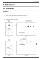
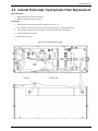
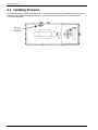
1
PGM-IR SF6 Monitor
Portable Gas Monitor for SF6 Gas
Instruction 3015-5150
Operation and Maintenance
Rev. 7 – December 2014
Patent 6,590,690
Product Leadership • Training • Service • Reliability
SF6 Portable Monitor
WARRANTY
Bacharach, Inc. warrants to Buyer that at the time of delivery this Product will be free from defects in material and
manufacture and will conform substantially to Bacharach Inc.'s applicable specifications. Bacharach's liability and Buyer's
remedy under this warranty are limited to the repair or replacement, at Bacharach's option, of this Product or parts thereof
returned to Seller at the factory of manufacture and shown to Bacharach Inc.'s reasonable satisfaction to have been
defective; provided that written notice of the defect shall have been given by Buyer to Bacharach Inc. within two (2) years
after the date of delivery of this Product by Bacharach, Inc.
Bacharach, Inc. warrants to Buyer that it will convey good title to this Product. Bacharach's liability and Buyer's remedy
under this warranty of title are limited to the removal of any title defects or, at the election of Bacharach, to the
replacement of this Product or parts thereof that are defective in title.
The warranty set forth in paragraph 1 does not apply to parts the Operating Instructions designate as having a limited shelflife or as being expended in normal use (e.g., filters).
THE FOREGOING WARRANTIES ARE EXCLUSIVE AND ARE GIVEN AND ACCEPTED IN LIEU OF (I) ANY
AND ALL OTHER WARRANTIES, EXPRESS OR IMPLIED, INCLUDING WITHOUT LIMITATION THE IMPLIED
WARRANTIES OF MERCHANTABILITY AND FITNESS FOR A PARTICULAR PURPOSE: AND (II) ANY
OBLIGATION, LIABILITY, RIGHT, CLAIM OR REMEDY IN CONTRACT OR TORT, WHETHER OR NOT
ARISING FROM BACHARACH'S NEGLIGENCE, ACTUAL OR IMPLIED. The remedies of the Buyer shall be limited
to those provided herein to the exclusion of any and all other remedies including, without limitation incidental or
consequential damages. No agreement varying or extending the foregoing warranties, remedies or this limitation will be
binding upon Bacharach, Inc. unless in writing, signed by a duly authorized officer of Bacharach.
Register Your Warranty by Visiting
www.mybacharach.com
Product improvements and enhancements are continuous; therefore the specifications and information
contained in this document may change without notice.
Bacharach, Inc. shall not be liable for errors contained herein or for incidental or consequential damages in
connection with the furnishing, performance, or use of this material.
No part of this document may be photocopied, reproduced, or translated to another language without the prior
written consent of Bacharach, Inc.
Copyright © 2014, Bacharach, Inc., all rights reserved.
®
BACHARACH is a registered trademark of Bacharach, Inc. All other trademarks, trade names, service marks
and logos referenced herein belong to their respective owners.
2
Instruction 3015-5150
SF6 Portable Monitor
Table of Contents
1 INTRODUCTION ....................................................................................................................................... 5
1.1
1.2
1.3
1.4
1.5
1.6
1.7
1.8
1.9
How to Use This Manual ................................................................................................................. 5
Warning Statements ........................................................................................................................ 5
Caution Statements ......................................................................................................................... 5
Hazard Symbols on Monitor ............................................................................................................ 5
Safety Precautions ........................................................................................................................... 6
1.5.1 Explosive Atmosphere ....................................................................................................... 6
1.5.2 Misuse and Modifications to Monitor ............................................................................... 6
1.5.3 Altitude Limit .................................................................................................................... 6
1.5.4 Cleaning ............................................................................................................................. 6
Unpacking and Initial Checks ......................................................................................................... 6
Shipping Precaution ......................................................................................................................... 6
Features and Capabilities................................................................................................................ 7
Functional Overview ........................................................................................................................ 7
2 SPECIFICATIONS ..................................................................................................................................... 8
3 OPERATION .............................................................................................................................................. 9
3.1 Front Panel Display and Controls .................................................................................................. 9
3.2 Connecting Gas-Sample and Exhaust Lines .................................................................................. 9
3.2.1 Overview ............................................................................................................................ 9
3.2.2 Connecting the Gas-Sample Line ..................................................................................... 9
3.2.3 Connecting the Exhaust Line (optional) ........................................................................ 10
3.3 Gas Detector Operation ................................................................................................................. 11
3.4 Time Weighted Average Operation ............................................................................................... 12
3.4.1 Overview .......................................................................................................................... 12
3.4.2 Starting a New or Continuing TWA/twa........................................................................ 12
3.5 Peak Reading Operation ................................................................................................................ 13
3.6 Leak Detector Operation ............................................................................................................... 13
3.7 Standby Mode ................................................................................................................................. 13
3.8 Battery – Charging and Using ...................................................................................................... 14
3.8.1 Charging the Battery ...................................................................................................... 14
3.8.2 Using the Battery ............................................................................................................ 14
3.9 Display Screens .............................................................................................................................. 14
3.9.1 Initial Power ON.............................................................................................................. 14
3.9.2 Filling the Purge-Air Bag ................................................................................................ 15
3.9.3 Data Display Screen ........................................................................................................ 15
3.9.4 Function Screens ............................................................................................................. 15
3.10 Working with System Faults ......................................................................................................... 18
3.10.1 Functional Overview ....................................................................................................... 18
3.10.2 Clearing / Silencing a Fault Alarm ................................................................................ 18
3.10.3 Viewing the Faults Log ................................................................................................... 18
3.11.4 Fault Codes ..................................................................................................................... 19
3.11 Working with the Gas Alarm ........................................................................................................ 20
3.11.1 Gas-Alarm Light .............................................................................................................. 20
3.11.2 Silencing a Gas Alarm ..................................................................................................... 20
3.12 Clearing the PPM & Faults Data .................................................................................................. 20
3.13 Working with the DIAG Function ................................................................................................. 20
3.13.1 Overview .......................................................................................................................... 20
3.13.2 Keypad Functions ............................................................................................................ 20
3.13.3 First Diagnostic Screen ................................................................................................... 21
3.13.4 Second Diagnostic Screen ............................................................................................... 21
3.14 Working with the P-CHK Function .............................................................................................. 22
3.14.1 Overview .......................................................................................................................... 22
3.14.2 Keypad Functions ............................................................................................................ 22
3.14.3 Screen Display ................................................................................................................. 22
Instruction 3015-5150
3
SF6 Portable Monitor
3.15 Print/Plot Logged Gas Levels ........................................................................................................ 23
3.16 Downloading Stored Data to a Personal Computer ..................................................................... 24
3.17 Importing Saved Data to a Spreadsheet ...................................................................................... 25
4 MAINTENANCE ...................................................................................................................................... 26
4.1 Disassembly.................................................................................................................................... 26
4.2 Internal Particulate / Hydrophobic Filter Replacement ............................................................. 27
4.3 Updating Firmware ....................................................................................................................... 28
5 PARTS AND SERVICE ........................................................................................................................... 29
5.1 Replacement Parts and Optional Items ....................................................................................... 29
Replacement Parts .......................................................................................................................... 29
Item Description ............................................................................................................................. 29
Part Number .................................................................................................................................. 29
Item Description ............................................................................................................................. 29
Part Number .................................................................................................................................. 29
5.2 Service Centers .............................................................................................................................. 29
4
Instruction 3015-5150
SF6 Portable Monitor
1 Introduction
1.1 How to Use This Manual
This manual provides important information on how to operate and service Bacharach’s Sulfur
Hexafluoride (SF6) Portable Monitor.
To assure operator safety and the proper use of the monitor, please read, understand, and follow the
contents of this manual.
If you have a working knowledge of gas monitors, you will find this manual useful as a reference tool. If
you are new to the use of gas monitors, you can educate yourself about the principles of gas detection and
the proper operation of this device by reading this manual thoroughly.
1.2 Warning Statements
The use of the word WARNING in this manual denotes a potential hazard associated with the use of this
equipment. It calls attention to a procedure, practice, or condition, or the like, which if not correctly
performed or adhered to, could result in personal injury or death.
1.3 Caution Statements
The use of the word CAUTION in this manual denotes a potential hazard associated with the use of this
equipment. It calls attention to a procedure, practice, condition, or the like, which if not correctly
performed or adhered to, could result in damage to the equipment.
1.4 Hazard Symbols on Monitor
This symbol indicates the need to consult this operating instruction manual when opening the
enclosure.
WARNING: A potential risk exists if the operating instructions are not followed.
This symbol indicates the presence of electric shock hazards when the enclosure is opened.
WARNING: To avoid risk of injury from electric shock, do not open the enclosure when power is
applied.
Instruction 3015-5150
5
SF6 Portable Monitor
1.5 Safety Precautions
HAZARDOUS AREA WARNING: This instrument has not been designed to be intrinsically safe
for use in areas classified as hazardous locations. For your safety, DO NOT use it in hazardous
(classified) locations.
COMBUSTIBLE/FLAMMABLE GAS WARNING: This is NOT a safety device. Some gases
which this instrument can detect may be combustible/flammable. When properly configured, this
instrument is designed to alarm at concentrations that are lower than the explosive limit of the
gas. As such, it is the buyer’s responsibility to initiate an immediate planned response to any gas
leaks as soon as they are detected. This equipment should NEVER be used to measure or
sample gases at or above their respective lower explosive limits.
1.5.1 Explosive Atmosphere
Do not operate this equipment in the presence of flammable liquids, vapors or aerosols. Operation of any
electrical equipment in such an environment constitutes a safety hazard.
1.5.2 Misuse and Modifications to Monitor
The protection provided by the monitor may be impaired if the monitor is used in a manner not specified
by these instructions. Changes or modifications to this monitor will void the warranty.
1.5.3 Altitude Limit
6,562 ft (2,000 m)
1.5.4 Cleaning
Clean the outside of the monitor’s case using a dry cloth — DO NOT use soap and water.
1.6 Unpacking and Initial Checks
Your SF6 Portable Monitor was carefully inspected at the factory before shipment, and packed so as to be
highly resistant to damage while in transport. When you receive the instrument, however, please unpack
it promptly and make a visual inspection to make sure that no damage has occurred during shipment. Also
check that all the following items have been received.
Item
SF6 Portable Monitor
Soft Carrying Case with
Shoulder Strap
Battery Pack & Charger
Instruction Manual
External Filter Assembly
Stainless Steel Probe
Elbow
Tubing (3 ft)
Qty.
1
Part Number
3015-5148
1
3015-5700
1
1
1
1
1
1
3015-5739
3015-5150
3015-5324
3015-5326
3015-3234
0003-6182
If damage was found, immediately file a claim with the carrier. If an item is missing, please contact
Bacharach’s Service Department for assistance (refer to Section 5.2 Service Centers).
1.7 Shipping Precaution
When shipping the instrument by air, deflate the purge-air bag to prevent it from bursting due to changes
in air pressure. Deflate the bag by selecting the EMTYBAG function as described on page 16.
6
Instruction 3015-5150
SF6 Portable Monitor
1.8 Features and Capabilities
•
•
•
•
•
•
•
•
Detects, measures, and displays the level of SF6 gas in the area being monitored
Measurement range of 0–1,000 ppm with a resolution of 1 ppm
Self contained purge-air bag, allowing the monitor to be used in a contaminated atmosphere
Automatically logs up to 200 gas readings that can be printed / plotted for analysis
Eliminates false alarms with use of non-dispersive IR source and sample draw system
Visual and audible gas alarm indictors that are turned ON when the detected gas level exceeds
a user defined trip-point
Extensive self diagnostics, providing both visual and audible indications when a fault occurs
Battery powered, providing 8–12 hours of operation
1.9 Functional Overview
The Bacharach Sulfur Hexafluoride (SF6) Portable Monitor is designed to detect, measure, and display the
concentration of SF6 gas in the area being monitored. To ensure accurate gas measurements, the monitor
self-zeros every 4 minutes using its internal supply of fresh air.
During normal operation the SF6 Monitor displays both the current gas level and the peak gas level
detected on its front panel LCD. The monitor retains a log of previous readings that can be easily accessed
at a later time for analysis.
Front panel indicators and an audible alarm are provided to signal gas alarm and instrument fault
conditions. The audible alarm can temporarily be silenced by a push of a button, but will reactivate if the
gas level is still above the alarm trip point after a user-defined time period has elapsed.
The SF6 Monitor requires only minor periodic maintenance such as the occasional replacement of filters.
The monitor incorporates active diagnostics that continuously check the system for proper operation. A
front panel indicator is provided to alert an operator of system malfunctions, and fault codes are generated
that enable the operator to quickly identify the cause of the fault.
Instruction 3015-5150
7
SF6 Portable Monitor
2 Specifications
Product Type ........................ Portable SF6 Gas Monitor
Measuring Range................. 0 to 1,000 ppm
Warm-Up Time .................... 5 minutes
Detector Type ....................... Infrared, Non-Dispersive
Sensitivity ............................ 1 ppm
Accuracy ............................... ±1 ppm
Response Time ..................... 90% of response within 3 seconds; 100% in 5 seconds
Temperature Drift ............... 1.5 ppm per °C between purge cycles
System Noise ....................... Less than 40 dB(A) at 10 ft (3 m)
Operating Temp ................... 32 to 122°F (0 to 50°C)
Ambient Humidity ............... 5 to 90% RH (non-condensing)
Altitude Limit ...................... 6,562 ft (2,000 m)
Power .................................... DC power pack, provides 8–12 hours of operation
Power Consumption ............ 15 Watts
Front Panel .......................... 3 Indicator lights:
ON – Green LED flashes during warm-up, and then glows steady
during normal operation
FAULT – Yellow LED flashes when there is a system fault
ALARM – Red LED flashes when the gas level is above its alarm setting
Audible Alarm ..................... Internal audible alarm programmable for any of the following conditions:
OFF, FAULT/ALARM, ALARM
Dimensions (DxLxW) .......... 9” x 14.5” x 5” (229 x 368 x 127 mm)
Weight .................................. Less than 9 lbs (4 kg) including battery
Valid Calibration Period
to Specifications ................... 12 months
Warranty .............................. 2 Years from date of shipment
8
Instruction 3015-5150
SF6 Portable Monitor
3 Operation
3.1 Front Panel Display and Controls
3.2 Connecting Gas-Sample & Exhaust Lines
3.2.1 Overview
A single gas-sample line needs to be run from the SF6 Monitor to the area to be monitored. If desired, an
optional exhaust line can be installed to vent SF6 gas away from the monitor.
3.2.2 Connecting the Gas-Sample Line
To connect the gas-sample line to the monitor, simply push the tubing onto the elbow connector and attach
the elbow to the Gas Sample Port on the front of the monitor as shown in the illustration below.
The gas-sample line can be up to 50 ft (15.2 m) in length. All tubing bends should have a radius of no less
than 5" to insure proper airflow. If kinks or obstructions occur in the line the monitor may not function
properly.
The end of this line should be placed near the potential leak source and positioned to reduce the possibility
of mists, aerosols, oil, water, dust, or other contaminates being drawn into the monitor.
An external filter (P/N 3015-5324) should be attached to the end of this line. See figure below.
Instruction 3015-5150
9
SF6 Portable Monitor
3.2.3 Connecting the Exhaust Line (optional)
The optional exhaust line carries the exhausted gas sample away from the monitor.
The exhaust line can be up to 50 ft (15.2 m) in length. Ideally this line should terminate outdoors in a
location that is not exposed to the elements.
Connect the exhaust line to the monitor by firmly pushing the tubing into the Exhaust Port’s push-toconnect (PTC) fitting. (See previous figure.) If the exhaust line terminates outside the building, position
the tubing so that no water or moisture can enter the line. Note that this line does not require a
termination filter.
To connect the exhaust line to the exhaust
port’s PTC fitting, firmly push the appropriate
tubing into the hole in the center of the
connector until it seats in the connector. Refer
to the figures at the left.
To remove tubing from a PTC connector, push
and hold the spring-loaded collar inwards,
then simultaneously withdraw the tubing.
Refer to the figures at the right.
10
Instruction 3015-5150
SF6 Portable Monitor
3.3 Gas Detector Operation
CAUTION: Operate the monitor in its horizontal position (handle facing upwards). Tilting the
monitor to a vertical position while in operation may cause inaccurate measurements to occur.
Turn ON the monitor as follows:
1. Lift up the shield located in front of the handle
2. Press the red power ON/OFF toggle switch.
3. Observe monitor’s firmware version is briefly displayed.
4. Observe that the NEW TWA/twa screen may appear, depending on
the configuration of the monitor’s TWA/twa function (refer to
Section 3.4 for detailed TWA operation).
5. Observe the monitor starts counting down its warm-up period of
300 seconds (5 minutes).
6. At the end of warm up, take the monitor to an area than contains
fresh air and press the ENTER button to fill the monitor’s internal
purge-air bag with clean, fresh air that is of the same temperature
and humidity as the area being monitored for gas. DO NOT fill the
purge-air bag in an area that is contaminated with SF6 gas.
After the purge-air bag is filled, observe the following as the monitor makes
gas measurements in the area being sampled:
•
MEASURE indicates when the monitor is actively measuring the
level of SF6 gas at the sampling point. The screen to the right shows
that currently 100 ppm is being measured. The measurement cycle
runs for 4 minutes.
A log of up to 200 previous measurements can be viewed using the
PPM LOG function (page 16), or printed as described in 3.16.
The 2ndUNIT value (Blank, Peak PPM, Continuous TWA, or 8 Hr
TWA) is user-selected (refer to 2ndUNIT function on page 17).
•
PURGE indicates when the monitor is resetting its infrared detector
to a baseline of 0 ppm using the air contained in the monitor’s
internal purge-air bag. The purge cycle runs for 10 seconds.
BACHARACH
VERSION x.xx
PRESS ENTER FOR
NEW TWA/twa
WARM UP
300
PURGE AIR EMPTY
(ENTER) TO FILL
RECHARGING PURGE
AIR...
MEASURE
2ndUNIT
100ppm SF6
PURGE
2ndUNIT
100ppm SF6
PURGE AIR EMPTY
<ENTER> TO FILL
The monitor will operate for approximately 40 minutes before the purge-air bag needs refilled.
When the message "PURGE AIR EMPTY" appears, take the monitor to a clean, fresh-air
environment and press the ENTER button to refill the bag.
Work with gas alarms and system faults as follows:
ALARM (red) light turns ON if the detected gas level exceeds a programmed alarm point. An audible
alarm also sounds if the AUDALRM function is activated (page 16) Pressing the front panel
SILENCE button turns OFF the audible alarm, but the ALARM light will continue to flash for as
long as the detected gas level is above the alarm point. The audible alarm will reactivate if the gasalarm condition is not cleared within the time period set by the SILENCE function (page 17).
FAULT (yellow) light turns ON if a fault occurs (see Fault Code list on page 19). An audible alarm
also sounds if the AUDALRM function is activated (page 16). Pressing the front panel SILENCE
button turns OFF the audible alarm, but the FAULT light continues to flash for as long as the fault is
present. The audible alarm will reactivate if the fault condition is not cleared within the time period
set by the SILENCE function (page 17). Both the FAULT light and audible alarm will automatically
turn OFF after the cause of the fault has been eliminated. A log of the last 30 fault events can be
viewed using the monitor’s FAULTS function (page 16).
Instruction 3015-5150
11
SF6 Portable Monitor
3.4 Time Weighted Average Operation
3.4.1 Overview
In addition to displaying the current SF6 level, the monitor can also calculate and display a Time
Weighted Average ppm value. This value is available in two formats (8 Hour or Continuous). This provides
users with the most appropriate data on their average ppm SF6 exposure in the working environment.
TWA operation is selected by using the 2ndUNIT function (page 17).
The two TWA formats are identified by the appearance of either “TWA” or ‘twa” in the upper-right corner
of the Data Display screen.
•
TWA (upper case letters) is calculated over an 8-hour period. This format is designed to show the
uers’s average ppm SF6 exposure level during a typical work day. After 8 hours has expired, an
asterisk (*) will be displayed but the TWA will continue to be updated.
PURGE
00TWA
100ppm SF6
•
twa (lower case letters) is continuously calculated over the operating time of the monitor. This
mode is useful for monitoring an area for a few minutes or more and is the preferred mode of
operation for checking operating room atmospheres.
PURGE
00twa
100ppm SF6
3.4.2 Starting a New or Continuing TWA/twa
When the monitor is turned ON the following message appears if the monitor is set up to display
TWA/twa.
PRESS ENTER FOR
NEW TWA/twa
Press either . . .
•
ENTER to start a new TWA/twa
•
ESC to continue with the current TWA/twa.
Tip: If NO button is pressed within 60 seconds the monitor automatically continues
with the current TWA/twa.
Note: During the time the monitor is OFF, the gas measurement is assumed to be zero
and will be factored into the TWA/twa calculation.
After selecting whether to start or continue a TWA/twa, the next screen shows the current elapsed
TWA/twa time.
ELAPSED TWA TIME
IS xx MINUTES
Where: xx is the accumulated time used by the monitor in calculating the TWA/twa.
12
Instruction 3015-5150
SF6 Portable Monitor
3.5 Peak Reading Operation
In addition to displaying the current SF6 level, the monitor can also be set up to display its peak ppm
measurement.
The peak reading display is selected by using the 2ndUNIT function (page 17).
PURGE
500pk
100ppm SF6
The display above shows that currently the monitor is detecting 100 ppm SF6 and that a peak
measurement of 500 ppm has occurred.
The peak reading is reset by pressing the ENTER button.
3.6 Leak Detector Operation
The monitor can be configured to operate as a Leak Detector by setting the AUDALRM function (page 16)
to LEAK DETECTOR.
When configured as a Leak Detector, the monitor will produce a leak detector type of audible feedback. At
zero ppm there will be a tic every 2 seconds with the tic rate increasing up to 20 tics per second when the
ppm level reaches the ALRMLVL (page 16) setting.
3.7 Standby Mode
After becoming operational, the monitor can be placed into a Standby Mode. When taken out of standby
the monitor is ready for operation without waiting an additional 5 minutes to warm up. While in standby
the monitor will stop taking gas samples and stops purging itself from the purge-air bag.
Place the monitor into its Standby Mode by pressing both the ENTER and ESC buttons at the same time.
STAND BY
Take the monitor out of standby by again pressing both the ENTER and ESC buttons.
When the monitor is taken out of standby the operator must refill the purge-air bag by pressing the
ENTER button. Refilling the bag after coming out of standby re-establishes the monitor’s ambient
pressure reading and ensures that the purge-air bag is filled at the start of taking gas measurements.
WARNING: Fill the purge-air bag in a clean, fresh-air environment that is at the
same temperature and humidity as the area being checked for gas. DO NOT fill the
bag in an area that is contaminated with SF6 gas.
.
PURGE AIR EMPTY
RECHARGING PURGE
<ENTER> TO FILL
AIR...
As soon as the purge-air bag has been refilled with fresh air, the Data Display screen appears and the
monitor resumes normal operation.
Instruction 3015-5150
13
SF6 Portable Monitor
3.8 Battery – Charging and Using
IMPORTANT: If you replace the original PGM-IR battery, refer to the installation instructions
included in the replacement kit, as the new replacement battery and cable may differ from the
original cable and battery.
IMPORTANT: Cables and sockets are sized appropriately. As general rules of thumb:
• Note the initial orientation of your power cable, and
•
Never force a connector into a socket.
3.8.1 Charging the Battery
The monitor is powered by a rechargeable battery pack located in a pouch on the side of the monitor’s soft
carrying case. The battery pack can be recharged at any time, regardless of the battery’s current charge state.
The lithium-ion battery will likely be partially charged. However, you should fully charge the battery prior to
operating the PGM-IR. Refer to the battery manufacturer’s instruction sheet for the proper charging procedure.
3.8.2 Using the Battery
To properly use the battery, follow the steps below.
1. The PGM-IR is designed for a 16VDC input. Set battery voltage output to 16V (refer to the battery
manufacturer’s instruction sheet for details).
2. The battery pack provided with your PGM-IR uses a power cable with a straight connector and a
90-degree elbow connector. The battery provided with your PGM-IR may differ slightly from the photos
shown in this manual, however, the 90-degree elbow connector must ALWAYS be the connector used
to supply power to the PGM-IR. Refer to the figure below.
To PGM-IR
3. Ensure that the battery is powered ON per the instruction label on the battery pack.
4. Verify that the battery is properly connected to the PGM-IR (see above).
A fully charged battery pack will power the monitor for a minimum of 8 hours.
3.9 Display Screens
3.9.1 Initial Power ON
When the monitor is first powered ON, all front panel lights turn ON and a splash screen appears showing
the monitor’s current firmware revision level. After a brief moment the Warm Up screen is displayed
along with the front panel ON light (green) blinking.
BACHARACH
WARM UP
VERSION x.xx
The monitor requires 5 minutes to warm up from a cold start; after which, the ON light glows steady and
the Data Display screen appears.
14
Instruction 3015-5150
SF6 Portable Monitor
3.9.2 Filling the Purge-Air Bag
CAUTION: Fill the purge-air bag in a clean, fresh-air environment that is at the same temperature
and humidity as the area being checked for gas. DO NOT fill the bag in an area that is
contaminated with SF6 gas.
The following message is displayed and an audible alarm is sounded when the monitor’s purge-air bag is
empty. This message appears immediately after warm-up, and approximately every 40 minutes during
normal operation. Press the ENTER button to start the refill process.
PURGE AIR EMPTY
RECHARGING PURGE
<ENTER> TO FILL
AIR...
After the air bag has been filled, the monitor starts or resumes normal operation by displaying the
Data Display screen.
3.9.3 Data Display Screen
MEASURE
2ndUNIT
PURGE
2ndUNIT
100ppm SF6
100ppm SF6
During normal operation the Data Display screen shows when the monitor is performing the following
two functions:
MEASURE indicates that the monitor is actively measuring gas. In the screen shown above the monitor is
currently detecting 100 ppm of SF6 gas. The 2ndUNIT value (Blank, Peak PPM, Continuous TWA, or 8 Hr
TWA) is user-selected (refer to 2ndUNIT function on page 17). The measurement cycle runs for 4 minutes.
PURGE is displayed when the monitor is resetting its infrared detector to a baseline of 0 ppm using the
fresh air in the monitor’s internal purge-air bag. The purge cycle runs for 10 seconds.
3.9.4 Function Screens
The Function screens are used to set up the monitor and display stored data.
From the Data Display screen, press both the Keypad Left and Right buttons at the same time to
display the first Function Menu screen. Next, use the Keypad buttons to move the arrow (>) until it
points to the desired function, and then press the ENTER button to select that function.
>FILLBAG EMTYBAG
ALRMLVL AUDALRM
>PPM LOG LOG INT
FAULTS
DIAG
>SILENCE
GAS
P-CHK
CLOCK
>2ndUNIT PRINT
PLOT
PC-DUMP
Once a function has been selected, use the Keypad to scroll through the displayed data or to change a
parameter associated with that function. Press ENTER to save any newly entered parameters. Press the
ESC button to return to the previous screen without saving.
Note that if no buttons are pressed within 90 seconds after selecting a function, the unit returns to the
Data Display screen.
FILLBAG – Press ENTER to manually fill the purge-air bag.
FILLING BAG...
WARNING: Fill the purge-air bag in a clean, fresh-air environment
that is at the same temperature and humidity as the area being
checked for gas. DO NOT fill the bag in an area that is
contaminated with SF6 gas.
Instruction 3015-5150
15
SF6 Portable Monitor
EMTYBAG – Press ENTER to manually empty the purge-air bag. Use
this function to drain the bag if it becomes contaminated with gas.
ALRMLVL – Detected gas level that causes the front panel ALARM
(red) light to turn ON and the audible alarm to sound (if AUDALRM
function is set to ALARM or ALARM/FAULT).
AUDALRM – The internal audible alarm is programmable to function as
follows:
DRAINING BAG...
EDIT ALARM LEVEL
300 ppm
AUDIBLE ALARM IS
ALARM
• OFF – Audible alarm is disabled.
• ALARM – Alarm sounds when detected gas level exceeds the ALRMLVL level as evidenced by the front
panel ALARM (red) light turning ON.
• ALARM/FAULT – Alarm sounds when either the detected gas level exceeds the ALRMLVL value, or if
a system fault occurs, as evidenced by the front panel ALARM (red) light or FAULT (yellow) light
turning ON.
• LEAK DETECTOR – When selected, the monitor will produce a leak detector type of audible feedback.
At zero ppm there will be a tic every 2 seconds with the tic rate increasing up to 20 tics per second when
the ppm level reaches the ALRMLVL setting.
• TWA ALARM – Audible alarm sounds when the TWA or twa, whichever is selected by the 2ndUNIT
Function, exceeds the ALARMLVL value.
The audible alarm can be temporarily silenced by pressing the SILENCE button (page 17).
PPM LOG – Contains records of the last 200 measurements. Each
record shows the measurement’s date, time, and ppm level.
Measurements are logged at an interval determined by the LOG INT
function. After all 200 locations are filled the newest entries overwrite
the oldest entries.
#025
7PPM @
07/11/05
15:35
Use the Keypad Up and Down buttons to change the record number by
a factor of 1. Use the Right and Left buttons to change the record
number by a factor of 10. Press ESC to return to the previous screen.
To the right, record #025 shows that a gas level of 7 ppm was measured
on 07/11/2005 at 3:35 PM.
The PPM Log can be cleared per Section 3.11.
LOG INT – Sets the interval at which measurements are logged to
memory from 1 to 9999 minutes. Factory default is 1 minute. The logged
measurements can be viewed using the PPM LOG function. Use the
Keypad to enter the desired value, and then press ENTER to save that
value and return to the previous screen.
FAULTS – Contains records of the last 30 fault events. The most recent
event is displayed when the Fault screen is first displayed. After 30
events have been recorded, the newest record overwrites the oldest. Each
record lists an event’s numeric fault code (refer to Section 3.10) plus the
date and time at which the event occurred. Use any of the Keypad
buttons to scroll through the other fault events. Press ESC to return to
the previous screen.
To the right, record #15 shows that a Purge Flow Fault (fault code
<1000>) occurred on 07/11/2005 at 12:37 PM.
DIAG – Enters the diagnostic function. Refer to Section 3.13.
16
LOG INTERVAL IS
0001 min
#15
<1000>
@
07/11/05
12:37
4.2159v
<0000>
29.05cD 14.58psi
Instruction 3015-5150
SF6 Portable Monitor
SILENCE – Sets the length of time the internal audible alarm is turned
OFF when the front panel SILENCE button is pressed. The factory default
is 30 seconds. If the cause of the gas-alarm has not been cleared at the end of
this time period, the internal audible alarm will reactivate. Use the Keypad
to enter the desired time period, and then press ENTER to save that value
and return to the previous screen.
P-CHK – The Pressure Check function displays the current manifold
pressure and the stored ambient pressure in psia, along with the difference
between these two pressures and the current fault code. Refer to
Section 3.14.
GAS – Displays Sulfur Hexafluoride (SF6) as the gas being monitored. No
other gas types are available for selection.
CLOCK – Sets the monitor’s date and time. Use the Keypad to enter
the correct date and time, and then press ENTER to save those values
and return to the previous screen. Note that time is displayed in a
24 hour format, while the date is displayed as mm/dd/yy.
2ndUNIT – One of following second measurements can be selected to
appear in the upper-right hand corner of the Data Display Screen:
• NONE – Blank
SILENCE TIMEOUT
0030 sec
14.07 * AMB14.05
-0.02dif
<1000>
SELECT GAS TYPE
SF6
SET DATE & TIME
07/11/05
MEASURE
15:30
00500pk
100ppm SF6
• Peak PPM – Peak gas reading
• Cont twa – Time Weighted Average calculated on a continuous basis
• 8hr TWA – Time Weighted Average calculated over an 8 hour period
PRINT – Refer to Section 3.15 Print/Plot Logged Gas Levels.
PLOT – Refer to Section 3.15 Print/Plot Logged Gas Levels.
PC-DUMP – A personal computer can be connected to the monitor’s DB9
RS-232 connector (refer to illustration in Section 3.15) for the purpose of
downloading logged ppm measurements. These measurements can later be
analyzed using any common spreadsheet program. Refer to Section 3.17 for
detailed instructions on how to transfer stored data to a personal computer.
Instruction 3015-5150
2ndUNI
>PRINT
PLOT
PC-DUMP
2ndUNIT
PRINT
>PLOT
PC-DUMP
2ndUNIT PRINT
PLOT
>PC-DUMP
17
SF6 Portable Monitor
3.10 Working with System Faults
3.10.1 Functional Overview
If a system malfunction occurs (see Fault Code list, page 19), the front panel FAULT light will flash and
the audible alarm, if activated (refer to AUDALRM function page 16), will start beeping.
3.10.2 Clearing / Silencing a Fault Alarm
The FAULT light and audible alarm will automatically turn OFF after the cause of the fault has been
eliminated.
Pressing the SILENCE button while a fault condition still exists causes the internal audible alarm to turn
OFF for a period of time as set by the SILENCE function (page 17). The front panel FAULT light will
continue to flash as a reminder that a fault condition still exists. At the end of the silence period if the
cause of the fault has not been corrected the audible-alarm circuit will reactivate.
3.10.3 Viewing the Faults Log
From the Data Display screen, press any of the Keypad buttons to display the first Function Menu
screen. Next, use the Keypad buttons to move the arrow (>) until it points to the FAULTS function, and
then press the ENTER button to display the Faults Log screen.
#03
<0800>
07/11/05
#04
08:17
<0000>
07/11/05
@
@
09:00
FAULT CODE<1800>
12
SAMPLE FLOW
FAULT CODE<1800>
13
PURGE FLOW
The Faults Log screen shows the monitor’s current fault status. If the
fault is still present when the FAULTS function is selected, then the
current cause of the fault is displayed along with the date and time it
occurred. If the cause of the fault has been cleared, then the Faults Log
screen will show <0000> along with the date and time the fault was
cleared. Use the Keypad buttons to scroll through the fault log. In the
screens shown to the left, record #03 shows that a Sample Flow Fault (fault
code <0800>) occurred on 07/11/2005 at 08:17 AM, while record #04 shows
that the fault was cleared on 07/11/2005 at 9:00 AM.
The cause of the fault is identified by a numeric fault code. To convert the
fault code into a text description of the fault, first press the ENTER button
and then use the Keypad buttons to scroll through the display until the
text description of the fault appears. If the fault code is a combination of
two or more faults, then continue to use the Keypad buttons until all fault
text descriptions have been displayed. For example, the fault code <1800>
represents the combination of both a Sample Flow <0800> and a Purge
Flow <1000> fault as shown to the left.
The Fault Log can be cleared as described under the heading Clearing the
PPM and Faults Data (Section 3.13).
18
Instruction 3015-5150
SF6 Portable Monitor
3.11.4 Fault Codes
Fault codes are additive. For example: A fault code of <0003> indicates that both a Box Temperature
Fault <0001> and a Bench Temperature Fault <0002> have occurred.
Code
Name
Description of Fault Condition
<0001>
Box
Temperature
Fault
Enclosure temperature is outside normal range (or IR detector has failed). Check that
the monitor is not being subjected to extreme temperatures. Use the DIAG function to
check the Box Temperature.
<0002>
Bench
Temperature
Fault
Optical bench is outside normal operating range (or IR detector has failed). Check that
the monitor is not being subjected to extreme temperatures.
<0004>
Manifold
Pressure Fault
The manifold pressure is outside its normal operating range (or IR detector has failed).
Enter the DIAG function and record ALL data. Call the factory with this information for
further instructions.
<0040>
Fill Flow
The purge-air bag’s pressure drop is outside expected limits. Use the EMTYBAG and
FILLBAG functions to refill the purge-air bag. If the fault still occurs, check for a
punctured bag or disconnected tubing.
<0080>
Over Range
Fault
<0100>
Zero Filter Fault
The air-purge bag is contaminated with gas. Take monitor to a clean-air area and use
the EMTYBAG and FILLBAG functions several times to decontaminate the purge-air bag.
<0200>
Gain Set Fault
The digipot autotune sequence has failed. This fault will only occur on first boot up or
after a firmware upgrade. Call the factory for further instructions.
<0400>
A/D Fault
A fault has occurred in the analog-to-digital circuitry. Contact the factory with this
information for further instructions.
<0800>
Sample Flow
Fault
Check for a restriction in the gas-sample inlet or exhaust, a blocked internal filter, or a
failed pump.
<1000>
Purge Flow
Fault
Check for a restriction in the gas-sample exhaust, a blocked internal filter, or a failed
pump. Once the purge air stream has been restored, the monitor will return to normal
operation after it completes a purge cycle.
<2000>
Bag Fill Time
The purge-air bag did not fill within the expected time allotment, or too many purge
cycles occurred indicating a leak in the purge-air system. Check for a punctured bag or
disconnected tubing.
<4000>
Zero Range
Fault
The IR detector’s output voltage is out of tolerance. Enter the DIAG function and record
all data. Call the factory with this information for further instructions.
<8000>
Clipping Fault
The detector voltage may be out of tolerance. Use the DIAG function to check the IR
detector voltage. Call the factory with this information for further instructions.
Instruction 3015-5150
Monitor exposed to a gas level that exceeded 65,000 ppm.
19
SF6 Portable Monitor
3.11 Working with the Gas Alarm
3.11.1 Gas-Alarm Light
If the detected gas level reaches the gas-alarm level as set by the ALRMLVL function, the front panel
ALARM (red) light will flash and the audible alarm, if activated (refer to AUDALRM function on page
16), will start beeping. The ALARM light and audible alarm will automatically turn OFF once the
detected gas level drops below the gas-alarm level.
3.11.2 Silencing a Gas Alarm
Pressing the SILENCE button while the alarm circuit is activated causes the audible alarm to turn OFF
for a period of time as set by the SILENCE function (page 17). The front panel ALARM light will continue
to flash as an indication that an alarm condition still exists. At the end of the silence period if the detected
gas level is still above the gas-alarm level the audible alarm will reactivate.
3.12 Clearing the PPM and Faults Data
Up to 200 gas measurements and 30 fault events are stored by the monitor.
To clear stored data, first display the data to be cleared by selecting the PPM LOG or FAULTS function
per Section 3.9.4. Next, press both the ENTER and Keypad Right buttons at the same time. A single,
long tone should be heard when the data has been successfully cleared.
3.13 Working with the DIAG Function
3.13.1 Overview
The DIAG function displays sensor data and status information useful to a service technician for
troubleshooting various fault conditions. Explanations of the data shown in these screens are given below.
3.13.2 Keypad Functions
From the Data Display screen, press any one of the Keypad buttons to display the first Function Menu
screen. Next, use the Keypad buttons to move the arrow (>) until it is next to the DIAG function, and
then press ENTER to display the first of two Diagnostic screens.
Press the Keypad Up button to toggle between the First and Second Diagnostic screen.
20
Instruction 3015-5150
SF6 Portable Monitor
3.13.3 First Diagnostic Screen
4.20885v
<0000>
Bench Voltage
Fault Code
29.05cD 14.58psi
Detector Temperature °C ∗ Pressure Reading
0.00075n
Noise
<0000>
35.40cB 14.59psi
Box Temperature °C
Fault Code
∗
Pressure Reading
In the First Diagnostic screen, the user can toggle between displaying Bench Voltage / Detector
Temperature, and Noise / Box Temperature by pressing the Keypad Right button.
Bench Voltage – This is the current peak-to-peak output of the IR detector. In the absence of gas this
value can range from 3.90000V to 4.50000V.
Noise –The Noise value is a 16 point running average of the noise portion of the IR detector’s output. This
reading is valuable mainly when gas is NOT present.
Detector Temperature – This is the current detector temperature in °C.
Box Temperature – This is the current internal enclosure temperature in °C.
Fault Code – Current fault code. A value of <0000> indicates that no faults are being detected.
Pressure Reading – This is the pressure as measured every purge cycle with the sample pump off and
the gas-sample inlet open. Its value is weather and altitude dependent and can range from 10.0 to
15.5 PSIA.
Purge Valve Asterisk (∗) – The purge valve can be opened and closed by pressing the Keypad Left
button. An asterisk appears on the display when the purge valve is open causing the monitor to draw air
from its purge-air port.
3.13.4 Second Diagnostic Screen
0.1ppm
0.01
0.00004au 4.210v
PPM Level
Avg. Absorption Unit
µMole/Liter
∗
Detector Voltage
PPM Level – Parts Per Million Level is the current detected gas level, and is the volume concentration
referenced to standard temperature and pressure.
Average Absorption Unit – This is the optical absorbency. In the absence of gas the absorbency is
0.00000 au. When sampling gas, its value varies proportionally with the gas concentration.
µMoles/Liter – This is the absolute concentration in micro-moles per liter of gas.
Detector Voltage – This is a running average of the IR detector’s bench voltage.
Purge Valve Asterisk (∗) – The purge valve can be opened and closed by pressing the Keypad Left
button. An asterisk appears on the display when the purge valve is open causing the monitor to draw air
from its purge-air port.
Instruction 3015-5150
21
SF6 Portable Monitor
3.14 Working with the P-CHK Function
3.14.1 Overview
The P-CHK function (Pressure Check function) (page 17) is useful to a service technician for
troubleshooting a flow-fault problem. The monitor will trigger a flow fault if the pressure drop from
ambient is less than 0.2 psi during a purge cycle, and 0.5 psi during a measurement cycle.
3.14.2 Keypad Functions
From the Data Display screen, press both the Keypad Left and Right buttons at the same time to
display the first Function Menu screen. Next, use the Keypad buttons to move the arrow (>) until it
points to the P-CHK function, and then press ENTER to display the Pressure screen.
The Keypad Left button toggles the purge valve open and closed. Note that an asterisk (*) appears when
the purge valve is open causing the monitor to draw air from the purge-air bag.
The Keypad Down button toggles the pump ON and OFF.
Pressing the ENTER button stores the current manifold pressure shown on the left to the ambient
pressure shown on the right (must be done with the pump OFF).
3.14.3 Screen Display
14.59
-0.16dif
AMB14.75
<0000>
Current Manifold Pressure
Pressure Difference
∗
Stored Ambient Pressure
Fault Code
Current Manifold Pressure – Current manifold pressure in psia.
Stored Ambient Pressure – Stored ambient pressure in psia.
Pressure Difference – Difference between the current manifold pressure and the stored ambient pressure.
Fault Code – Current fault code (page 19).
Purge Valve Asterisk (∗) – The purge valve can be opened and closed by pressing the Keypad Left
button. An asterisk appears on the display when the purge valve is open causing the monitor to draw air
from the purge-air bag.
22
Instruction 3015-5150
SF6 Portable Monitor
3.15 Print/Plot Logged Gas Levels
A printout or plot of the last 200 SF6 ppm measurements can be made by connecting the optional
Bacharach printer and printer cable to the monitor as follows (refer to Section 5.1 for printer and cable
part numbers):
1. For a printout or plot to be made, the monitor must have been set up to record gas measurements
using the LOG INT function (page 16).
2. Interconnect the RS-232 connectors located on the printer and monitor.
3. If not already done, refer to the printer manual and set the printer’s communication
parameters to:
•
•
•
•
Data bit = 8
Parity = None
Baud rate = 19200
Handshaking = DTR
4. From the Data Display screen, press both the Keypad Left and
Right buttons at the same time to display the first Function
Menu screen. Next, use the Keypad buttons to move the arrow (>)
until it points to either PRINT to produce a printout, or PLOT to
generate a plot.
2ndUNIT
PLOT
>PRINT
PC-DUMP
5. Press ENTER to start the print/plot process.
Instruction 3015-5150
23
SF6 Portable Monitor
3.16 Downloading Stored Data to a Personal Computer
Using the monitor’s PC DUMP feature (page 17), the last 200 SF6 gas readings that were stored in
memory can be downloaded to a personal computer in ASCII text, comma-delimited format, which can
then be imported into most spreadsheet programs for analysis.
The following describes how to download data to a computer using Windows® HyperTerminal as the
communications program. If a different operating system and/or communications program is being used,
then consult the appropriate instruction manuals for those products.
1. Install serial data cable P/N 104-4027 (straight through, 6 foot, DB9 male to DB9 female) between
the computer’s COM port and the analyzer’s RS-232 connector. (For computers having a 25-pin
COM port, either use a 25-pin to 9-pin adapter, or use a serial cable with appropriate connectors
on each end.)
2. At the computer, start HyperTerminal by doing one of the following:
• If HyperTerminal has already been set up to communicate with the SF6 Monitor, then click Start,
point to Programs, point to Accessories, point to Communications, click HyperTerminal, and
double-click the file name or icon that has been associated with the SF6 Monitor.
• If HyperTerminal has never been run in association with the SF6 Monitor, then a new
HyperTerminal connection needs to be made as follows:
a) Click Start; click Run. In the Run box type “hypertrm.exe” and click OK. The New
Connection dialog box should appear.
b) Type in a New Connection Name such as “SF6”. Click OK to select the default icon (if
desired, select a different icon before clicking OK). The Connect To dialog box should
appear.
c)
Click the Connect using drop-down menu and choose the COM port to which the analyzer
is connected. Then click OK to display the COM Properties dialog box for that COM port.
d) Set Port Settings to:
- Bits per second: 19200
- Data bits: 8
- Parity: None
- Stop bits: 1
- Flow control: None
Then click OK to display HyperTerminal’s main window.
e) Click File; click Save. This creates a file with an .ht extension in the folder C:\Program
Files\Accessories\Hyper Termina, using the name that was entered in Step b.
3. After HyperTerminal is running: click Transfer, click Capture Text, and then click Start to accept
the default drive\directory\filename to which all received data will be stored as an ASCII text file.
Note: By default, the captured text file will be stored on the hard drive at C:\Program
Files\Accessories\HyperTerminal\CAPTURE.TXT. If desired, click Browse to select a different
drive, directory and filename. The next time data is captured, it will be stored under the same
location and filename.
Tip: Changing the filename extension to “CSV” (comma separated variable) will allow the file to be
directly opened in the spreadsheet program. For example, double clicking the filename
CAPTURE.CSV in Windows Explorer will automatically start Microsoft Excel and load the file.
24
Instruction 3015-5150
SF6 Portable Monitor
4. From the Data Display screen, press both the Keypad Left and Right buttons at the same time
to display the first Function Menu screen. Next, use the Keypad buttons to move the arrow (>)
until it points to PC-DUMP, and then press the ENTER button to begin the download process.
2ndUNIT
PRINT
5. Observe that the SF6 Monitor’s screen goes blank and that HyperTerminal displays the data as it
is being received. After all data has been transmitted, the SF6 Monitor re-displays the Function
Menu screen.
6. To stop capturing data and save it, click Transfer, click Capture Text, click Stop.
7. HyperTerminal and the connection to the SF6 Monitor can now be closed.
3.17 Importing Saved Data to a Spreadsheet
A text file that was created as described in Section 3.16 can be imported into spreadsheet programs that
are capable of importing comma-delimited files.
The following describes how to generate a spreadsheet from a comma-delimited text file using Microsoft
Excel 2003. If you are using a different spreadsheet program, please refer to its instruction manual for
information on how to import comma-delimited text files.
1. Start Microsoft Excel.
2. Click Data, Import External Data, and Import Data to display the “Select Data Source”
dialog box.
3. Locate file saved earlier. Select file, then click “Open” to display Excel’s “Text Import Wizard.”
4. Choose the “Delimited” original data type option and click Next.
5. Check the “Tab,” “Comma,” and “Space” delimiters and click Finish.
6. Choose “Existing worksheet” or “New worksheet” and click OK to create spreadsheet.
Note: A worksheet must be open in order to import data.
Instruction 3015-5150
25
SF6 Portable Monitor
4 Maintenance
4.1 Disassembly
When servicing the parts inside the SF6 Monitor, disassemble the monitor’s metal chassis as follows:
Items Required:
•
Medium Phillips head screwdriver
Procedure:
1. Remove monitor and its battery pack from the soft carrying case.
2. Unplug battery pack from monitor.
3. Remove a total of 10 screws from the locations shown in the illustrations below.
4. Carefully separate the metal chassis.
Instruction 3015-5150
26
SF6 Portable Monitor
4.2 Internal Particulate / Hydrophobic Filter Replacement
Items Required:
•
•
Replacement filter (P/N 0007-1654)
Medium Phillips head screwdriver
Procedure:
1. Disassemble the monitor’s metal chassis per Section 4.1.
2. See illustration below and locate the internal particulate / hydrophobic filter.
3. Pull off tubing from both ends of filter and remove filter from instrument.
4. Attach tubing to new filter
5. Reassemble monitor.
Instruction 3015-5150
27
SF6 Portable Monitor
4.3 Updating Firmware
An RS-232 connector, located on the top panel, is used to update the monitor’s firmware. Reprogramming the
instrument with updated firmware should be done by qualified service technicians only using instructions
provided by Bacharach.
28
Instruction 3015-5150
SF6 Portable Monitor
5 Parts and Service
5.1 Replacement Parts and Optional Items
Replacement Parts
Item Description
Part Number
SF6 Monitor
3015-5148
Replacement Battery Kit
3015-5739
Soft Carrying Case with Shoulder Strap
3015-5700
Bladder Bag Kit
3015-5325
Stainless Steel Probe
3015-5326
External Filter
3015-2906
Hydrophobic Filter
0007-1654
External Filter Assembly
3015-5324
Tubing (3 ft)
0003-6182
Replacement Pump
3015-4239
Battery (for main PCB board)
0204-0020
Replacement Bench
3015-4561
Optional Accessories
Item Description
Part Number
IrDA Printer (includes printer, roll of thermal
paper, 4 x AA batteries, manual)
0024-1400
Thermal printer paper, 1 roll
0006-8733
Thermal printer paper, 5 rolls
0024-1310
Cable (DB9 to RJ-45)
3015-4214
Computer Communications Cable (DB9 male to
DB9 female)
0104-4027
5.2 Service Centers
Service and replacement parts can be obtained by contacting any of the following
Bacharach Service Centers:
United States
Bacharach, Inc.
621 Hunt Valley Circle
New Kensington, PA 15068
Phone: 724-334-5051
Fax: 724-334-5723
Email: [email protected]
Instruction 3015-5150
Canada
Bacharach of Canada, Inc.
20 Amber St. Unit #7
Markham, Ontario L3R SP4
Canada
Phone: 905-470-8985
FAX: 905-470-8963
E-mail: [email protected]
29
Headquarters:
621 Hunt Valley Circle, New Kensington, PA 15068-7074
Toll Free: 800-736-4666 • Tel: +1-724-334-5000 • FAX: +1-724-334-5001
Website: www.MyBacharach.com • E-mail: [email protected]
Printed in U.S.A.
® Registered Trademark of Bacharach Inc.