1
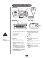
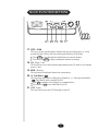
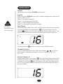
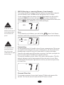
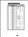
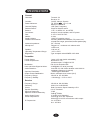
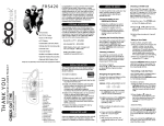
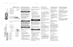
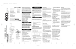
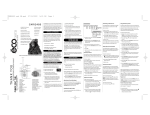
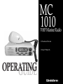
MC
1010
VHF Marine Radio
Channel Scan
Dual Watch
OPERATING
GUIDE
CONTENTS
OF YOUR USER’S MANUAL
CONTENTS
Introduction . . . . . . . . . . . . . . . . . . . . . . . . . . . . . . . . . . . . . . . .
1
Included with your package. . . . . . . . . . . . . . . . . . . . . . . . .
1
Optional Accessories . . . . . . . . . . . . . . . . . . . . . . . . . . . . . .
1
Installation . . . . . . . . . . . . . . . . . . . . . . . . . . . . . . . . . . . . . . . . .
2
Convenient Features of the MC1010 . . . . . . . . . . . . . . . . . .
2
Choosing a Location . . . . . . . . . . . . . . . . . . . . . . . . . . . . . .
2
Engine Noise Suppression . . . . . . . . . . . . . . . . . . . . . . . . . .
2
Antenna considerations. . . . . . . . . . . . . . . . . . . . . . . . . . . .
3
Installing the MC1010 . . . . . . . . . . . . . . . . . . . . . . . . . . . .
3
Care and Maintenance . . . . . . . . . . . . . . . . . . . . . . . . . . . . . .
3
Controls and Indicators . . . . . . . . . . . . . . . . . . . . . . . . . . . . . . . . 4
Front Panel . . . . . . . . . . . . . . . . . . . . . . . . . . . . . . . . . . . . .
4
Rear Panel . . . . . . . . . . . . . . . . . . . . . . . . . . . . . . . . . . . . . .
4
LCD Panel . . . . . . . . . . . . . . . . . . . . . . . . . . . . . . . . . . . . . .
4
Multi Function Buttons . . . . . . . . . . . . . . . . . . . . . . . . . . . . .
5
Operation . . . . . . . . . . . . . . . . . . . . . . . . . . . . . . . . . . . . . . . . . .
6
On/Off . . . . . . . . . . . . . . . . . . . . . . . . . . . . . . . . . . . . . . . .
6
Squelch . . . . . . . . . . . . . . . . . . . . . . . . . . . . . . . . . . . . . . . .
6
Dual Watch . . . . . . . . . . . . . . . . . . . . . . . . . . . . . . . . . . . . .
6
Chanel Selection . . . . . . . . . . . . . . . . . . . . . . . . . . . . . . . . .
6
Instant Channel 16 . . . . . . . . . . . . . . . . . . . . . . . . . . . . . . . .
6
Introduction
Installation
Controls and
Indicators
Operation
MEM (Entering or removing Memory Scan Channels) . . . . . 7
Scan . . . . . . . . . . . . . . . . . . . . . . . . . . . . . . . . . . . . . . . . . . .
7
Transmitting. . . . . . . . . . . . . . . . . . . . . . . . . . . . . . . . . . . . .
7
Transmit Time Out . . . . . . . . . . . . . . . . . . . . . . . . . . . . . . .
7
Channel and Functions . . . . . . . . . . . . . . . . . . . . . . . . . . . . . . .
8
Specifications . . . . . . . . . . . . . . . . . . . . . . . . . . . . . . . . . . . . . . .
9
Specifications
Warranty . . . . . . . . . . . . . . . . . . . . . . . . . . . . . . . . . . . . . . . . . . . 10
INTRODUCTION
The Uniden MC1010 VHF marine radio transceiver has been designed to give you a
rugged, reliable instrument that will provide you with years of trouble-free service.
You need to read this Operating Guide thoroughly to acquaint yourself with the characteristics
and operation of your transceiver.
Be sure to complete the Product Registration Card.
Keep your receipt as proof-of-purchase in case warranty service is required.
Included with your package
1 x Mounting Bracket and Screws
2 x Bracket thumb screws
1 x Mic. hang up Bracket and Screws
1 x DC Power lead
Optional Accessories
Flush mounting bracket for ‘in dash’ installation. Extension speaker.
Please contact your local Uniden supplier for information
Features, Specifications and availability of Optional Accessories are all subject to change without notice.
1
INSTALLATION
Convenience features of the MC1010
NOTE
The MC1010 will only
operate with 12 volt
negative ground batteries.
Universal mounting bracket - this allows you to install the MC1010 horizontally on top
or to the underside of a shelf, on a bulkhead or overhead.
Remote speaker jack - for use with an optional extension speaker.
Plug-in type connections - for easy removal of the MC1010.
Internal speaker - positioned for convenient in-dashboard mounting using the optional
flush mount bracket.
Choosing a location
When deciding on the most suitable location for your MC1010 you need to take into account
electrical, mechanical and environmental elements that may effect its performance.
NOTE
The MC1010 is NOT
waterproof. Select a
mounting location that is
protected from water.
Antenna - The antenna needs to be located as high as possible and clear of metal objects.
The performance range of the MC1010 is directly related to the antenna height. The cable
to the antenna should be as short as possible. Long antenna leads can cause substantial
loss of performance for both receiving and transmitting.
Moisture/Sunlight - Select a location that is sheltered from moisture and out of direct
sunlight.
Battery leads - Try to mount the MC1010 close to the battery (within the range of the
supplied power leads). If this is not possible, any extension needs to be made with #10
AWG wire. For long extensions a larger wire gauge should be used.
Compass - Due to possible electromagnetic interference the MC1010 and any extension
speakers should not be mounted close to a compass.
Cooling - The location of the MC1010 should permit clear air flow to the heat sink at the
rear of the radio.
Engine Noise Suppression
Interference generated from the electrical systems of engines is sometimes a problem with
radios. The MC1010 has been designed to be essentially impervious to ignition impulse
noise and alternator noise. However, in some installations it may be necessary to take
measures to further reduce the effect of noise interference. All DC battery wires, antenna
lead, and accessory cables should be routed away from power cabling carrying particularly
high currents.
In severe cases of noise interference, it may be necessary to install a noise supression kit.
2
Antenna Considerations
NOTE
The power cord is
equipped with a fuse to
protect the radio. Use
only a 6 Amp fast blow
fuse when replacing.
NOTE
Always mount the
MC1010 horizontally never facing upwards, as
it will collect water.
A variety of antenna is available from a number of quality suppliers. It is recommended
you draw upon the advice of your retailer when choosing a suitable antenna to suit your
vessel and range requirements. In general, the communication range is increased by using
a high-gain antenna placed as high as possible above the water line. Antennas should be
located away from metal objects and not have excessively long coaxial feed cables.
Installing the MC1010
After you have considered the various factors affecting your choice of location, position the
radio (with the bracket, microphone, power cord, antenna and any auxiliary cables installed)
into the selected location and operate it to ensure there is no interference with surrounding
fittings.
Mark the location of the mounting bracket, remove it from the radio and use the bracket
as a template to position the fixing holes for drilling.
Screw fix the mounting bracket using the screws compatible with the mounting surface.
Connect the red wire of the supplied power cord to the positive (+) battery terminal.
Connect the black wire to (-) battery terminal.
Connect the power cord to the keyed connector on the DC power lead (see page 4)
Install the radio in the mounting bracket and connect all cables and accessories to the
appropriate jacks and connectors.
CARE AND MAINTENANCE
Your MC1010 is a precision piece of electronic equipment and needs to be treated accordingly.
Due to the rugged design, very little maintenance is required, however a few precautions
should be observed.
If your radio has been accidentally subjected to moisture, you should immediately wipe
it down with a soft cloth dampened with fresh water - then dry it off.
If the antenna has been damaged, you should not transmit except in case of emergency.
A defective antenna may cause damage to your radio.
You are responsible for the continued AS/NZS 4415 technical compliance of your radio.
You are urged to arrange for periodic performance checks with your local Uniden marine
dealer.
3
CONTROLS AND INDICATORS
Front Panel
5
2
4
CHAN
1
VOLUME
TX
HI LO
SCAN M E M
1
MC1010
DUAL
16
0
SCAN
STEP
MEM
LITE
H/L
2
3
SQUELCH
6
3
Rear Panel
LCD Panel
7
13 14 15 16
12
9
TX HI LO
SCAN MEM
10
11
8
1 PTT - Microphone - ‘Push To Talk’ button. 10 LCD Numerical Channel Display Indicates Channel Number in use.
2 VOLUME (On/Off/Volume) 11
(Dual Watch) - Indicates Dual
Turns the MC 1010 On or Off and varies
NOTE
LCD Indicators appear
when selected by
pressing the
corresponding button.
the audio volume.
3 SQUELCH - Eliminates background
noise when no signal is being received.
4 LCD Panel
Watch has been selected.
12 SCAN - Indicates that you are scanning
the channels in memory.
13 TX (Transmit) - Indicates when
transmitting.
5 CHAN - Used to manually select
the desired Communication Channel
14 HI (High) - Indicates transmitted output
power is 25 Watts.
6 ‘Multi Function Buttons’ see page 5.
7 DC Power - Connect to the supplied
15 LO (Low) - Indicates transmitted output
8 Remote Speaker Jack - An external, 4 Ohm,
16 MEM (Memory) - Indicates if the
power is 1 Watt.
Power Cord.
displayed channel is in memory for
scanning.
4 Watt speaker may be connected to this
jack. The connecting wire must have a
miniature plug.
9 Antenna Connector - Connect the antenna
here using a type PL259 plug.
4
MULTI FUNCTION BUTTONS
1
MC1010
DUAL
16
0
SCAN
STEP
MEM
LITE
H/L
2
3
SQUELCH
21 20 19 18 17
17 STEP - SCAN
This key is used to step through the channels that are stored in memory- or - when
pressed and held, this key also starts and stops the Memory SCAN mode.
Press STEP to step through the channels that are stored in memory.
Press and hold STEP to begin scanning the channels in memory.
18 H/L - (High / Low)
This key allows you to switch between high transmit power (25 watts) or low transmit
power (1 watt).
19 MEM - (Memory)
This key enters the displayed channel into scan memory.
20 16 - Dual Watch
This key allows rapid access to Emergency Channel 16 - or - when pressed and held
Dual Watch will be switched On/Off.
Press 16 to instantly access Channel 16 communications.
Press and hold 16 to turn Dual Watch On/Off.
21 LITE - (Light)
This key is used to turn the LCD back light on and off.
5
OPERATION
On/Off
Turn the unit on by rotating the VOLUME control clockwise.
Squelch
NOTE
Dual Watch is
automatically activated
when scanning begins.
Adjust the 4 position SQUELCH rotary switch to eliminate background noise and select the
signals you wish to receive.
Position 0 - (all signals) - squelch off.
Position 1 - (weak signals) squelch threshold
Position 2 - (medium signals) squelch medium
Position 3 - (strong signals only!) squelch maximum.
Dual Watch
Dual Watch monitors channel 16 for activity every two seconds while scanning or monitoring.
To activate Dual Watch, press and hold button 16 until two short beeps occur. The
indicator
appears on the LCD panel, indicating Dual Watch mode is in effect. If the
signal is received on channel 16, the radio remains on channel 16 until the signal ends.
HI
Press and hold button 16 until the tone sounds to cancel Dual Watch mode.
Channel Selection
To select a channel manually, press the CHAN selector buttons ( /
) to select the
desired channel. Communication channels are located on Channels 01 - 28, 60 - 69
and 71 - 88.
Instant Channel 16
To access instant Channel 16, press button 16 . This overrides the channel selected with the
CHAN selector buttons or any scanning activity. The Channel Display indicates the unit is
on Channel 16. Press button 16 again. The transceiver will return to the channel selected.
prior to accessing instant Channel 16 communications. The Channel display will indicate
the selected channel.
6
MEM (Entering or removing Memory Scan channels)
You can enter channels into memory for instant scanning at any time. When a channel is
selected for Memory Scan, the MEM indicator will appear on the LCD display.
To enter a channel number into memory, select the channel number you want stored by
pressing the CHAN Selector button, then press MEM . To remove a channel from
memory, select the channel you want to remove by pressing the channel selector button, then
press the MEM button. MEM will be removed from the display.
MEM
NOTE
At least two channel
numbers must be entered
into the memory before
the scan function will
operate.
Scan
To scan channels stored in Memory, press and hold the STEP button. In the Memory
Scan Mode, the MC1010 scans only those channel numbers previously entered into Memory.
SCAN
MEM
NOTE
If no channel has been
entered into Memory
Scan, the error tone
sounds and the LCD panel
does not change.
Transmitting
One watt transmit power (LO) should be selected for most commuunications. This prevents
your signal from interfering with other vessels communications, and will work fine unless
maximum range is required. Press the H/L button until LO is shown in the display.
Twenty-five watt transmit power (HI) provides a great range. It will allow your signal to be
heard over weaker signals. It should be used only when necessary.
To activate the transmitter, press the ‘Push to Talk’ switch on the microphone. TX will be
displayed, indicating a signal is being transmitted. Release the switch to receive. When
transmitting hold the microphone approximately 5cm from your mouth and speak clearly
in a normal voice.
LO
Transmit Time Out
If you transmit continuously for more than 5 minutes, TX flashes and transmit will be
cancelled. The Time Out tone will sound until the PTT button is released.
7
CHANNEL AND FUNCTIONS
CHANNEL
DESIG
01
02
03
04
05
06
07
08
09
10
11
12
13
14
15
16
17
18
19
20
21
22
23
24
25
26
27
28
60
61
62
63
64
65
66
67
68
69
71
72
73
74
77
78
79
80
81
82
83
84
85
86
87
88
FREQUENCY (MHz)
TRANSMIT RECEIVE
156.050
156.100
156.150
156.200
156.250
156.300
156.350
156.400
156.450
156.500
156.550
156.600
156.650
156.700
156.750
156.800
156.850
156.900
156.950
157.000
157.050
157.100
157.150
157.200
157.250
157.300
157.350
157.400
156.025
156.075
156.125
156.175
156.225
156.275
156.325
156.375
156.425
156.475
156.575
156.625
156.675
156.725
156.875
156.925
156.975
157.025
157.075
157.125
157.175
157.225
157.275
157.325
157.375
157.425
160.650
160.700
160.750
160.800
160.850
156.300
160.950
156.400
156.450
156.500
156.550
156.600
156.650
156.700
156.750
156.800
156.850
161.500
161.550
161.600
161.650
161.700
161.750
161.800
161.850
161.900
161.950
162.000
160.625
160.675
160.725
160.775
160.825
160.875
160.925
156.375
156.425
156.475
156.575
156.625
156.675
156.725
156.875
161.525
161.575
161.625
161.675
161.725
161.775
161.825
161.875
161.925
161.975
162.025
TYPE
OF TRAFFIC
Public Corresp,Duplex
Public Corresp,Duplex
Public Corresp,Duplex
Public Corresp,Duplex
Public Corresp,Duplex
Com’l, SAR Ops
Public Corresp,Duplex
Com’l, Port Ops
Port Ops
Port Ops
Port Ops
Port Ops
Port Ops
Port Ops
Simplex
Safety Calling
Simplex
Duplex
Duplex
Port Ops,Duplex
Duplex
Duplex
Public Corresp,Duplex
Public Corresp,Duplex
Public Corresp,Duplex
Public Corresp,Duplex
Public Corresp,Duplex
Public Corresp,Duplex
Public Corresp,Duplex
Public Corresp,Duplex
Public Corresp,Duplex
Public Corresp,Duplex
Duplex
Duplex
Public Corresp,Duplex
Safety Calling
Port Ops
Simplex
Fishing
Port,Non Com’l/Com'l
Non Com’l
Com’l
Non Com’l,Fishing
Com’l
Port Ops
Duplex
Duplex
Duplex
Public Corresp,Duplex
Public Corresp,Duplex
Public Corresp,Duplex
Public Corresp,Duplex
Public Corresp,Duplex
Public Corresp,Duplex
8
SHIP
SHIP
TO SHIP TO SHORE
No
No
No
No
No
Yes
No
Yes
Yes
Yes
No
No
Yes
No
Yes
Yes
Yes
Yes
Yes
No
Yes
No
Yes
Yes
Yes
Yes
Yes
Yes
Yes
Yes
No
Yes
No
No
No
No
No
No
No
No
No
No
Yes
Yes
Yes
Yes
Yes
Yes
Yes
Yes
Yes
Yes
No
Yes
No
Yes
Yes
Yes
Yes
Yes
Yes
Yes
Yes
No
No
Yes
No
Yes
Yes
No
Yes
Yes
No
No
No
No
No
No
Yes
Yes
Yes
Yes
Yes
Yes
SPECIFICATIONS
General
Channels:
Controls:
Status Indicators:
Channel Display:
Selector Switch:
Buttons:
Connectors:
Size:
Weight:
Supply Voltage:
Standard Accessories:
Antenna Impedance:
Microphone:
Speaker:
Operating Temperature Range:
Regulations:
Transmit: 54
Receive: 54
On/Off, Volume, Squelch
TX, SCAN,
, HI, LO, and
MEM,on LCD Panel
LCD (Dual 7 segment)
Channel Selector switch
LITE, 16, MEM, H/L, and STEP
Antenna, remote speaker, and DC power
2 1/5"H x 6 2/5"W x 8"L
2.4 lbs
13.8V DC negative ground
Mounting bracket and hardware, DC power cord,
microphone hanger, spare fuse,remote speaker plug.
50Ω nominal
Rugged 1kΩ condenser mic element with
coiled cord
1.82 inch, 8Ω
–10°C~+55°C
Type accepted underAS/NZS 4415:1996
Transmitter
Power Output:
Power Requirement:
Modulation:
Hum and Noise Signal-to-Noise:
Audio Distortion:
Spurious Emmission:
Output Power Stabilization:
Frequency Range:
Frequency Stability:
1 watt or 25 watt (switch selectable)
Not rated on LO;
25 watts output: [email protected] DC
FM ±5 kHz deviation Max.
42 dB@300 HZ, 3kHz (nominal)
Less than 3% with 3 kHz deviation with 1000 Hz
modulating frequency (nominal)
- 36dBm @ 25 Watts Max.
Built-in automatic level control (ALC)
156.025 to 157.425 MHz
±1.58 kHz @ – 10°C to +55°C
Receiver
Frequency Range:
Sensitivity:
Circuit:
Squelch Sensitivity:
Spurious Response:
Adjacent Channel Selectivity:
Audio Output Power:
Power Requirement:
IF Frequencies:
156.300 to 162.025 MHz
0.28µV for 20 dB SINAD
Dual Conversion Super Heterodyne PLL
0.4µV Threshold
75 dB
73dB @±25KHz
2.7watts (10% Distortion)
210mA @ 13.8V DC squelched
520mA @ 13.8V DC at maximum audio output
1st -21.4 MHz
2nd - 455 kHz
9
MC1010
MC1010
Mic,
www.uniden.com.au
www.uniden.co.nz
10
FOR PURCHASING A UNIDEN PRODUCT
THANK YOU
© 2001
Uniden Australia Pty Limited
Uniden New Zealand Limited
Printed in the Philippines
UTZZ 01883ZZ