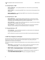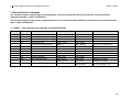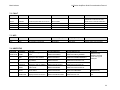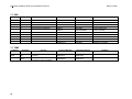
1
Serial Protocol No53 No532 Serial Protocol FCC Notice This equipment has been tested and found to comply with the limits for a Class B digital device, pursuant to Part 15 of the FCC Rules. These limits are designed to provide reasonable protection against harmful interference in a residential installation. This equipment generates, uses and can radiate radio frequency energy and, if not installed and used in accordance with the instructions, may cause harmful interference to radio communications. However, there is no guarantee that interference will not occur in a particular installation. If this equipment does cause harmful interference to radio or television reception, which can be determined by turning the equipment off and on, the user is encouraged to try to correct the interference by one or more of the following measures: • Reorient or relocate the receiving antenna. • Increase the separation between the equipment and the receiver. • Connect the equipment into an outlet on a circuit different from that to which the receiver is connected. • Consult the dealer or an experienced radio/TV technician for help. Caution! Changes or modifications not expressly approved by the party responsible for compliance could void the user’s authority to operate the equipment. Canada This Class B digital apparatus complies with Canadian ICES-003. Cet appareil numérique de la Classe B est conforme à la norme NMB-003 du Canada. Mark Levinson and the Mark Levinson logo are trademarks of Harman International Industries, Incorporated, in the United States and/or other countries. Microsoft and Windows are registered trademarks of Microsoft Corporation in the United States and/or other countries. TM For customer service and product shipment information, refer to the www.marklevinson.com Web site. Part No. 070-18998| Rev 1 |10/08 Other company and product names may be trademarks of the respective companies with which they are associated. ©2008 Harman International Industries, Incorporated. All rights reserved. This document should not be construed as a commitment on the part of Harman International Industries, Incorporated. The information it contains is subject to change without notice. Harman International Industries, Incorporated assumes no responsibility for errors that may appear within this document. Mark Levinson 1 No5 Series Amplifiers Serial Communications Protocol Documents 1.1 Change List 4 4 2 Definitions, Acronyms, and Abbreviations 4 3 General Description 5 4 Ethernet Port & Cable Configuration 4.1 Physical Connection using Ethernet Cables 5 5 5 Message Formats and Examples 5.1 Format of the Message Fields 5.2 Incoming Messages 5.3 Outgoing Messages 5.3.1 RSP – Response to Command Request 5.3.2 NTF – Notification of System Action 5.4 Example Request - RQST 5.5 Example Response - RSP 5.6 Example Notification - NTF 6 6 7 7 7 7 8 8 8 6 7 RQST Error Responses and Examples External Protocol Commands 7.1 DSPLY – This command only applicable to the No53 Amplifier 7.2 FAULT 7.3 NOP 7.4 HWSTATUS 7.5 PWR 7.6 TEMP 8 10 10 11 11 11 12 12 8 Critical Fault Notifications 13 9 Notification Factory Defaults 13 3 No5 Series Amplifiers Serial Communications Protocol Mark Levinson 1 Documents The following documents should also be used with this document to understand how this protocol can be used with the No5 Series Amplifiers. 070-18285 No53 Reference Monaural Power Amplifier Owner’s Manual 070-18979 No532 Dual Monaural Power Amplifier Owner’s Manual 1.1 Change List No changes have been made. 2 Definitions, Acronyms, and Abbreviations \r represents the ASCII new line control character (0x0D) : External Protocol String Field Separator , External Protocol String Field Parameter Separator for multiple parameters ACK Acknowledge AV Audio Video System generated response CMD Command CS Control Source EOP End of Packet HOST The device initiating or receiving the serial communication packets to/from the amplifier. ML Mark Levinson o 4 N 5xx The Mark Levinson amplifier product receiving or transmitting the serial communication packets to/from the HOST. NAK/NACK No Acknowledge NTF Notification PARAM Parameter RM Resource Manager RQST Request RSP Response SOP Start of Packet SPLUT Serial Protocol Lookup Table SPG Serial Protocol Guidelines UI User Interaction User Parameter A user changeable variable that stores a specific value that describes an operating condition for the amplifier. No5 Series Amplifiers Serial Communications Protocol Mark Levinson 3 General Description An external host controller can use the external protocol to control and monitor the operation of the No5 Series Power Amplifiers. The protocol consists of simple ASCII character set based commands, which are passed to the amplifier as command packets via the Ethernet port. The amplifier will reply to command packets with an acknowledgement to signify that the command has been recognized and acted upon. Ethernet cable EXTERNAL HOST (Controller) No5 Series Power amplifier 4 Ethernet Port & Cable Configuration The No5 series power amplifiers are capable of obtaining a dynamically allocated IP address when connected to a DHCP server and the Network User Options are configured to use the DHCP server (default behavior). The DHCP setting can be modified via the internal Web page of the amplifier. Refer to the amplifier’s user manual for further instructions. The amplifier setup for Ethernet Control is defaulted to Auto-Negotiate and recommends the end point to also be configured for Auto-Negotiation. However, the amplifiers are capable of: • 10/100 BaseT • Half/Full-duplex • flow control • Pause control Note: These parameters are NOT user-adjustable. 4.1 Physical Connection using Ethernet Cables If using a Direct-to-Ethernet capable Component, use a Crossover Ethernet Cable. PC/Controller (TCP Client) Mark Levinson Power Amplifier Crossover Cable If using a router or switch, use a straight through Ethernet Cable. Router Controller (TCP Client) Straight Cable Straight Cable Mark Levinson Power Amplifier 5 No5 Series Amplifiers Serial Communications Protocol Mark Levinson 5 Message Formats and Examples The external protocol consists of a structured format string with specific fields used to indicate: Message type Source of the command Command Status/Parameter Messages can be transmitted to (incoming) and received from (outgoing) the amplifier to facilitate system control via the Ethernet connection. 5.1 Format of the Message Fields All incoming and outgoing messages must use the following format: HDR:SRC:CMD:PARAM\r where: HDR The Header field specifies the type of message: RQST – incoming request RSP – outgoing response NTF – outgoing notification. SRC The Source field specifies the source of the message: CS – message from a Control Source UI – message from a User Interaction AV – used by notifications to indicate and event was caused by the component without user interaction. CMD The Command field specifies the command selected from the External Protocol Commands table to invoke the desired functionality. PARAM The Parameter field specifies the selected parameter from the External Protocol Commands table to achieve the desired effect. Fields are separated by a colon “:” and messages are terminated with a ‘\r’ control character (0x0d). All fields, commands and associated parameters are case sensitive and must be entered as listed in the External Protocol Commands table. Do not insert spaces in message sequences, unless they are indicated in the table. Maximum message size is 60 characters, including the line ending ASCII control character ‘\r’ (0x0D). When an incoming or outgoing message uses more than one parameter, the individual parameters must be separated by commas. HDR:SRC:CMD:PARAM1,PARAM2,PARAM3,…\r When an incoming command requires multiple parameters per request (RQST), ALL parameters for the given command must be entered AND in the order presented in the External Protocol Commands table, as the descriptors are not utilized in the parameter field of the command/response string. The response message also follows these guidelines. 6 Mark Levinson No5 Series Amplifiers Serial Communications Protocol 5.2 Incoming Messages The Header Field (1st field) of every external protocol string indicates the type of message contained within the transmitted string. All incoming messages to the amplifier contain the string “RQST” in the header field. Any other string in the header field indicates an outgoing message. The control source that issued the Request (RQST) expects a reply within 500ms after receipt of the string to indicate that the message was received. This response can be an acknowledgement (ACK), the requested action if a data parameter was requested, or a WAIT to indicate the system has received the command but needs additional time to process the request. NOTE: When an incoming request is received, the system acknowledges receipt of the string within 500ms of receiving the incoming message. 5.3 Outgoing Messages Outgoing Messages are generated to acknowledge an incoming request, to provide requested information, or to inform of a system action occurring. As with an incoming message, the Header field is used to indicate the type of message contained within the string. Outgoing messages will be a response (RSP) to a request or a system generated notification (NTF) message. 5.3.1 RSP – Response to Command Request An outgoing RSP will be generated as the result of an incoming RQST. In most cases the response is an acknowledgement (ACK) unless the request is a query “?”. In the case of a query, the RSP contains the requested parameter, rather than an ACK. 5.3.2 NTF – Notification of System Action An NTF is generated as the result of a system action occurring. When commands are issued to the system, they are placed in a queue in the order they are received. When the command is acted upon and the requested action has completed or occurred, a notification is generated within the system. If enabled, the notifications are sent if a user manually manipulates the front panel buttons or controls, presses IR keys on the remote control, issues an RQST via External Protocol to instruct the system to perform an action, or if a system fault is detected. When a NTF event occurs, the source field indicates the source of the event: UI (user interaction) AV (component generated) fault It’s important to note that Notifications are only sent to the Controller if they are enabled. See the Notification Factory Defaults section of this document for the factory default settings. See the External Protocol Commands section in this document for more information. Also, as commands are issued to change the state of a notification event (enable it or disable it), the external protocol notification database is updated to store this new state information, so that user configured notification states are automatically restored when the amplifier is power cycled. However, the user configured states are reset to Factory Defaults at any time that the factory default settings are restored. 7 No5 Series Amplifiers Serial Communications Protocol Mark Levinson 5.4 Example Request - RQST RQST:CS:PWR:ON\r - incoming Request (RQST) from a Control Source (CS) commanding Power (PWR) ON. RQST:CS:PWR:?\r - incoming Request (RQST) from a Control Source (CS) querying the Power (PWR) state. RQST:CS:PWR:NTF?\r - incoming Request (RQST) from a Control Source (CS) querying the Power (PWR) Notification state. 5.5 Example Response - RSP RSP:CS:PWR:ACK\r – outgoing Response (RSP) generated from a Control Source request, indicating the command (PWR) is valid and the parameter supplied during the request is within the expected range, acknowledging (ACK) the request is being processed. RSP:CS:PWR:ON\r – outgoing Response (RSP) generated from a Control Source query request, indicating the command (PWR) current state is (ON). RSP:CS:PWR:EN\r – outgoing Response (RSP) generated from a Control Source notification state query request, indicating the command (PWR) notification is enabled (EN). 5.6 Example Notification - NTF NTF:UI:PWR:ON\r – outgoing Notification generated from a User Interaction (UI), indicating the command power (PWR) has turned ON. NOTE: Notifications for a specific command must be enabled for system generated messages. 6 RQST Error Responses and Examples The External Protocol responds with the following message parameters when an unexpected Incoming Request string is detected. If these responses are received, please verify spelling, spacing and capitalization of all characters of the failing field. The format of the response message string indicates where the error has been detected, as shown in the examples: 8 INVALID_SRC – The entered Source is not a valid source and is not recognized by the system. Example: RSP:INVALID_SRC\r – received if sending RQST:Cs:PWR:ON\r INVALID_CMD – The entered Command is not a valid command and is not recognized by the system. Example: RSP:CS:INVALID_CMD\r – received if sending RQST:CS:PWr:ON\r INVALID_PRM – The entered Parameter is not a valid parameter for the given command, or is out of the acceptable range for the command. Example: RSP:CS:VOL:INVALID_PRM\r – received if sending RQST:CS:PWR:On\r Mark Levinson No5 Series Amplifiers Serial Communications Protocol INVALID_STR – The entered Request String is not formatted correctly and is not valid. Example: RSP:CS:INVALID_STR\r – received if sending QST:CS:PWR:ON\r, or RQST:CSPWR:ON\r NACK – The incoming request is Not Acknowledged, indicating the system is in Standby and the request is being ignored. Example: RSP:CS:PWR:NACK\r – received if sending RQST:CS:PWR:ON\r while the system is in Standby and the Link2 master is in Standby. WAIT/ERROR – If the system is unable to process a request (RQST) within 500mS, the external protocol automatically generates the WAIT response indicating the system needs additional time for processing. Up to 3 wait responses can occur before the system responds with ERROR, signifying it is unable to process the request. The typical response format is utilized, with the command field representing the name of the command that the system needs additional time to process. Example: RSP:CS:PWR:WAIT\r RSP:CS:PWR:WAIT\r RSP:CS:PWR:WAIT\r RSP:CS:PWR:ERROR\r 9 No5 Series Amplifiers Serial Communications Protocol Mark Levinson 7 External Protocol Commands The command examples under the field “Incoming Request” assumes the keywords RQST:CS: precedes the command parameter indicated in the table, i.e. RQST:CS:PWR:ON\r The command examples under the field “Outgoing Response” must include the keyword RSP:CS: preceding the response indicated in the table, i.e. RSP:CS:PWR:ACK\r 7.1 DSPLY – This command only applicable to the No53 Amplifier Command DSPLY Parameter Function Incoming Request Outgoing Response Comment SETFB SET2 Sets Display to Full Brightness Sets Display Brightness to Setting 2 DSPLY: SETFB\r DSPLY: SET2\r DSPLY:ACK\r DSPLY:ACK\r SET1 Sets Display Brightness to Setting 1 DSPLY: SET1\r DSPLY:ACK\r OFF Turns Display OFF DSPLY: OFF\r DSPLY:ACK\r ? Request Current Display Setting DSPLY:?\r DSPLY:SETFB\r Display set to Full Brightness DSPLY:?\r DSPLY: SET2\r Display Brightness at Set level 2 DSPLY:?\r DSPLY: SET1\r Display Brightness at Set level 1 DSPLY:?\r DSPLY: OFF\r Display is OFF EN Enables Notification DSPLY:EN\r DSPLY:ACK\r DIS Disables Notification DSPLY:DIS\r DSPLY:ACK\r NTF? Query Notification State DSPLY:NTF?\r DSPLY:EN\r Notification is Enabled DSPLY:NTF?\r DSPLY:DIS\r Notification is Disabled Command is ignored because the system is in Standby mode. DSPLY:NACK\r 10 No5 Series Amplifiers Serial Communications Protocol Mark Levinson 7.2 FAULT Command FAULT Parameter THERM Function Incoming Request A critical system fault has occurred PWR SIGNAL UNKNOWN Outgoing Response Comment See the section “Critical Fault Notifications” in this doc for more details on this command notification Not Available Not Available Not Available Not Available 7.3 NOP Command NOP Parameter NOP Function No operation is performed Incoming Request NOP:NOP\r Outgoing Response NOP:ACK\r Comment Used for testing communication 7.4 HWSTATUS Command Parameter HWSTATUS NAME HWSTATUS:STATICIP\r MASK Display the static IP address. Displays the IP address of the subnet mask. DHCP DHCP Status HWSTATUS:DHCP\r Outgoing Response Example: HWSTATUS:NO53_00005B\r Example: HWSTATUS:AABBCCDDEEFF\r Example: HWSTATUS:192.168.10.10\r Example: HWSTATUS:192.168.50.3\r Example: HWSTATUS:255.255.255.0\r HWSTATUS:ENABLE\r HWSTATUS:DISABLE\r HWSTATUS:MLNETVER\r Example: HWSTATUS:v0.1.0\r MAC IP STATICIP MLNETVER Function Display the assigned host name. Incoming Request Display the MAC address. Display the Internet Protocol (IP) address. HWSTATUS:MAC\r Displays the ML Net version. HWSTATUS:NAME\r HWSTATUS:IP\r HWSTATUS:MASK\r Comment Response Only. Outgoing response column lists typical examples. Response only. For Customer Service use. 11 No5 Series Amplifiers Serial Communications Protocol Mark Levinson 7.5 PWR Command PWR Parameter Function Incoming Request Outgoing Response ON STANDBY Amp Powered ON from Standby Place Amp into Standby Mode PWR:ON\r PWR:STANDBY\r PWR:ACK\r PWR:ACK\r LP Place Amp into Low Power Mode PWR:LP\r PWR:ACK\r ? Request Current PWR State Comment PWR:?\r PWR:ON\r System Powered ON PWR:?\r PWR:STANDBY\r System in Standby PWR:?\r PWR:LP\r System in Low Power PWR:EN\r PWR:ACK\r EN Enables Notification DIS Disables Notification PWR:DIS\r PWR:ACK\r NTF? Query Notification State PWR:NTF?\r PWR:EN\r Notification is Enabled PWR:NTF?\r PWR:DIS\r Notification is Disabled 7.6 TEMP Command TEMP Parameter ALL BOX 12 Function Requests all available temperatures in the box Requests the overall ambient temperature inside the amplifier Incoming Request Outgoing Response TEMP:ALL\r TEMP:ACK\r TEMP:BOX\r TEMP:ACK\r Comment No5 Series Amplifiers Serial Communications Protocol Mark Levinson 8 Critical Fault Notifications System Error Fault Message Over Temp (Internal) Amplifier is operating at excessive temperature. NTF:AV:FAULT:THERM\r Power Fail Condition Power failure due to over voltage, under voltage, or AC line power is outside of the line frequency limits. NTF:AV:FAULT:PWR\r Signal Fault Indicates to Controller that the Component has had a General Signal Fault with ML Net or Link2 attached devices NTF:AV:FAULT:SIGNAL\r System Software General signal fault due to excessive DC offset or excessive output current. NTF:AV:FAULT:UNKNOWN\r 9 Notification Factory Defaults Command Factory Default Setting DSPLY NOP NTF PWR N/A N/A YES Notes No Notification not available for this command Notification not available for this command 13