1
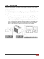
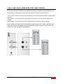
GKMX-42
GUITAR / UNIT SELECTOR
SOUND
USER’S MANUAL
Rev. 2013-11-15
© Copyright Primova AB 2013
GKMX-42
Guitar/Unit Selector
1
Table of contents
GKMX-42
Guitar/Unit Selector ............................................................................................. 3
INTRODUCTION ...................................................................................................................... 3
13-PIN CONNECTORS ............................................................................................................. 3
POWERING THE UNIT ............................................................................................................. 4
USING THE DEVICE WITHOUT A SYNTHESIZER....................................................................... 4
INPUT AND OUTPUT CONNECTIONS .......................................................................................... 5
INPUT GK CONNECTORS AND INPUT GUITAR JACKS ............................................................. 5
OUTPUT CONNECTORS “GK A” & “GK B” ............................................................................... 5
“SEND” / “RECEIVE” JACKS ..................................................................................................... 6
CONTROLS .................................................................................................................................. 7
“SEL” FOOT SWITCH ............................................................................................................... 7
“A/B” FOOTSWITCH................................................................................................................ 7
“BOTH” FOOTSWITCH ............................................................................................................ 7
“S1”/”S2” FOOTSWITCHES AND “S1/S2 CTRL”....................................................................... 8
“VOL A” AND “VOL B” JACKS WITH “GTR”/”MAX” SWITCH................................................... 9
GKMX-42
Guitar/Unit Selector
2
GKMX-42
Guitar/Unit Selector
INTRODUCTION
The GKMX-42 stomp box is a four-channel switching device for 13-pin GK equipped guitars
as well as standard guitars and guitar synthesizers. The unit allows you to quickly grab a new
guitar, hit the foot switch and take off with the next song in a live situation. The device is
sturdy and within a small footprint (170x120 mm).
The 13-pin inputs are compatible with Roland GC-1 or any other 13-pin GK-3, GK-2 or GK-KIT
equipped guitar.
Note: For standard guitars connected to one of the input jacks, only the regular pickup signal
will be available to the output synthesizer unit. This unit does NOT convert regular pickups to
MIDI.
The 13-pin outputs A and B are to be connected to one or two guitar synthesizers,
compatible with Roland GR-55, VG-99, GR-D, GR-S or earlier synthesizers.
13-PIN CONNECTORS
The 13-pin connectors are soldered to the printed circuit board. Please do not use more
force or violence than required.
GKMX-42
Guitar/Unit Selector
3
POWERING THE UNIT
The GKMX device and can be powered by either unit A or B, selecting the unit with highest
voltage. However in this mode there is a small risk that the total current could lead to
clipping/distortion or possible unit failure.
A second (safer) method is to connect a 12VDC adapter rated 0.8-1.5A with a 2.1 mm plug
(not included). In this mode there’s no current drawn from the synth unit. The adapter will
provide enough current to power the GKMX unit and any connected 13-pin guitar.
To be on the safe side, we recommend the following:
1. IF YOU ARE CONNECTING MORE THAN TWO 13-PIN GUITARS, ALWAYS USE A
12VDC ADAPTER (rated 0.8A - 1.5A) WITH THE GKMX-42.
2. MAKE SURE THAT THE CENTER HOLE OF THE 12VDC CONNECTOR IS 0V AND THE
SLEEVE IS +12VDC OTHERWISE PROTECTIVE COMPONENTS INSIDE THE GKMX
DEVICE MAY GET DAMAGED.
3. IF THE LAMPS (LEDS) DO NOT IMMEDIATELY LIGHT UP WHEN CONNECTING THE
ADAPTER, REMOVE THE PLUG AND VERIFY THE VOLTAGE AND POLARITY.
Technical information:
Available supply current, Roland guitar synth:
200 mA
Loads:
Maximal GKMX internal power consumption:
40 mA
GK-3 or GK-KIT maximal power consumption/guitar: 30 mA (each)
Calculation on four connected GK-3 guitars:
40 + (4 x 30) = 160mA (i.e. less than 200mA, which is OK)
Only the GK3 pickup type has been measured. Other pickups may consume much more
power. If you don’t know the power consumption of your 13-pin guitar, you should follow
our recommendation shown above and connect a 12VDC adapter.
USING THE DEVICE WITHOUT A SYNTHESIZER
If the device is powered by a 12VDC adapter it allows you to use this device also for gigs
where you choose not to bring your guitar synthesizer. Just connect the SEND jack to a
regular guitar amplifier and play the selected GK or regular guitar.
GKMX-42
Guitar/Unit Selector
4
INPUT AND OUTPUT CONNECTIONS
INPUT GK CONNECTORS AND INPUT GUITAR JACKS
The unit supports up to four connected guitars. Each input channel has two input
connectors, one Roland 13-pin GK compatible connector and one regular guitar jack.
The jack inputs are buffered and mixed into the GTR signal chain to the output devices.
1. A regular guitar may be connected to the input guitar jack of the channel.
2. A 13-pin GK-Ready guitar may be connected to the GK-input of the channel.
3. For a GK-3 guitar the 2CM (two-cable-method) may be used, connecting the regular
guitar pickups straight to the input jack using a separate guitar cable and connecting
the GK hex pickup to the input GK connector using a 13-pin cable.
Note: If both channel inputs are used at the same time, i.e. connecting both a GK guitar and
a regular guitar at the same channel, the two sounds will be mixed together.
OUTPUT CONNECTORS “GK A” & “GK B”
Up to two 13-pin compatible guitar synthesizer units may be connected. They are referred to
as A and B. If an external 12DC adapter is not connected any of the connected units will
power the device and your guitars. Read the section “Powering the unit” for further
information.
The recommended max total 13-pin cable length (including cable between guitar and
GKMX-42, and cable from GKMX-42 to the synthesizer) is 10 meters.
INPUT AND OUTPUT CONNECTIONS
5
“SEND” / “RECEIVE” JACKS
Prior to the selected normal guitar pickup signal (GTR) gets to the output devices it is also
available at the SEND jack.
The RECEIVE jack has a buffered input stage and is connected to the GTR signal of the output
devices. If the RECEIVE jack is not used, the signal goes directly from SEND to RECEIVE
internally.
These jacks allow you to:
- Insert optional effect pedals before the regular guitar pickup signal (GTR) gets to the
synthesizer.
- Connect SEND to optional effect pedals and further to a guitar amplifier bypassing
the synthesizer analog/digital circuitry.
- Use the hexaphonic pickup for various guitar sound emulations in the synthesizer
(i.e. GR-55, GR-D, GR-S etc.) and then connect the Guitar out or Left or Right synth
output to the RECIEVE jack and then use further processing in the synthesizer (i.e
GR-55) as if the simulated GTR signal was coming directly from you guitar.
INPUT AND OUTPUT CONNECTIONS
6
CONTROLS
“SEL” FOOT SWITCH
The “SEL” footswitch is used to select one of the input channels.
This switch will cycle through the input channels when engaged.
A miniature rocker switch located on the rear panel allows you to
select the maximum number of inputs for cycling. Select 2, 3 or 4
guitars.
This allows you to use a mix of up to four GK equipped and/or
regular guitars on stage easily selectable with a stomp of your
foot.
“A/B” FOOTSWITCH
This is the pedal switch that allows you to select which device is to
be played, either the one connected to the A connector, or the
one connected to B.
The red LED is ON – Unit A will sound and the S1 and S2 buttons
located at the guitar is routed to unit A.
The green LED is ON – Unit B will sound and the S1 and S2 buttons located at the guitar is
routed to unit B.
“BOTH” FOOTSWITCH
When switched ON, this foot switch allows you to play both of
the devices connected to the A and B connectors at the same
time.
The yellow LED is ON – Both units will sound. This setting does
not affect the S1/S2 routing.
CONTROLS
7
“S1”/”S2” FOOTSWITCHES AND “S1/S2 CTRL”
The guitar-mounted S1 and S2 buttons are always in A/B mode, i.e. operating on the unit
selected by the A/B footswitch.
The device footswitches S1 and S2 can be configured using the “S1/S2 CTRL” rotary switch.
The “S1/S2 CTRL” rotary switch has four positions:
“A”
S1 and S2 footswitches operate on unit A
“B”
S1 and S2 footswitches operates on unit B
“AB”
S1 and S2 footswitches operates on both unit A and B
“A/B”
S1 and S2 footswitches operates on the currently selected unit A or B depending
on the A/B footswitch setting.
The above possibilities allowing guitar and footswitch S1/S2 commands to different units
allow you to fully control the synth units.
CONTROLS
8
“VOL A” AND “VOL B” JACKS WITH “GTR”/”MAX” SWITCH
These two stereo jacks allow you to optionally connect an expression pedal (Roland EV-5 or
compatible) to individually control the synth volume of channel A and channel B.
There is also a switch for each channel allowing you to control how the volume pedal should
operate:
GTR position - The VOL control on the GK guitar will still control the overall master synth
volume.
MAX position - The max volume will be independent of the guitar volume settings.
NOTE: WHEN A VOLUME PEDAL IS CONNECTED AND THE UNIT IS IN “MAX” POSITION, THE
UNIT WILL SOUND (ASSUMING PEDAL IS DEPRESSED) EVEN IF THE UNIT IS NOT SELECTED
USING THE “A/B” OR “BOTH” FOOTSWITCH.
CONTROLS
9
WARRANTY
PRIMOVA AB WARRANTS THE GKMX PRODUCT FOR ONE YEAR. TWO YEARS IF INSIDE EU.
LIMITATION OF LIABILITY AND WARRANTY
NO WARRANTIES OF DAMAGES TO CONNECTED EQUIPMENT OR CABLES.
NO WARRANTIES IF UNSUITABLE VOLTAGE HAS BEEN APPLIED TO CONNECTORS.
PRIMOVA AB ONLY WARRANTS THE GKMX UNIT ITSELF.
CONNECTING THE GKMX UNIT OR THE GKMX BOARD, TO OTHER COMPONENTS SUCH AS
GUITARS OR SYNTHESIZERS IS AT OWN RISK.
IN NO EVENT WILL PRIMOVA BE LIABLE FOR DIRECT, INDIRECT, SPECIAL, INCIDENTAL, OR
CONSEQUENTIAL DAMAGES ARISING OUT OF THE USE OR THE INABILITY TO USE THE GMXUNIT EVEN IF ADVISED OF THE POSSIBILITY OF SUCH DAMAGES. IN PARTICULAR,
PRIMOVA IS NOT RESPONSIBLE FOR ANY COSTS INCLUDING BUT NOT LIMITED TO THOSE
INCURRED AS A RESULT OF LOST PROFITS OR REVENUE, LOSS OF USE OF THE GKMX
PRODUCT, LOSS OF DATA, THE COST OF SUBSTITUTING THE GKMX-UNIT, OR ANY CLAIMS BY
THIRD PARTIES.
© Copyright Primova AB Sweden 2013
PRIMOVA AB
Kurlandaallén 21
68151 Kristinehamn
Sweden
www.primovasound.com
[email protected]
CONTROLS
10