1
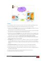
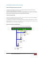
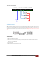
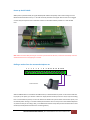
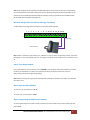
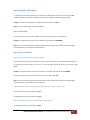
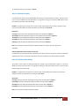
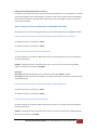
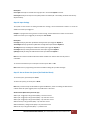
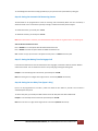
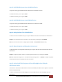
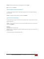
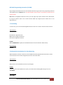
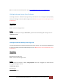
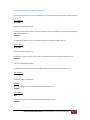
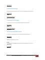
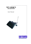
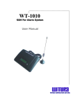
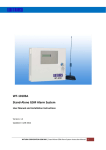
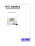
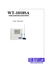
VERSION: 1.1 UPDATED: 9 Dec 2012 WT‐1010S GSM Alarm Panel (Alarm Backup) USER MANUAL Description The WT‐1010S GSM Alarm Panel is a wireless communicator for alarm and fire panels that uses the cell phone network (GSM) to transmit alarms and other panel event. The module checks the status of the PSTN line and in case the PSTN line becomes unavailable, the WT‐1010S GSM emulate the line signal to the panel. At this time, the panel will dial out using the GSM cell phone network to communicate with the receiver at the monitoring station and transmit the alarms. The WT‐1010S can use as the below function: 1. Telecom landline backup. Usually, the alarm panel will use telephone line as the main transmission and use GSM modem as the backup. If landline is been cut by the intruder, the alarm will call out using GSM modem. This method is widely used in the places that security is highly important. For example, bank, jewellery shops, notebook house, ATM machines and etc where double protection on properties is required. 2. The second function is to connect the GSM dialer to the alarm panel as the main communicator and use at the places 3. without telecom landline. This unit also acts like the low cost basic alarm system. It also can use like the GSM alarm system without any alarm panel. WITURA CORPORATION SDN BHD | WT‐1010S GSM Alarm Panel User Manual V1.1 1 General Overview WITURA CORPORATION SDN BHD | WT‐1010S GSM Alarm Panel User Manual V1.1 2 Features Panel compatibility – Allows any contact ID alarm panel to transmit alarms over GSM using the GSM voice channel. Works over the GSM cell phone networks units can be used wherever there is cell phone coverage. Telephone line backup: WT‐1010S give priority to the lowest cost network. WT‐1010S uses the telephone line as the main transmission line and uses the GSM voice channel as backup. Auto restart system: It can continuously monitor the system status of its own. When there is a problem with the SIM card or the module is not working properly, it will automatically restart the system. Programmable Account Number: WT‐1010S has built‐in alarm inputs that allow the unit to send additional signals (with user programmable Account number) to the monitoring station. The Alarm Events that available in this system are PSTN Failure, AC Failure and Auto Test. Supported Protocol: Pager message (DTMF with handshake) Automatically send alarm messages to use programmable cell phone number (SMS) when ZONE1, ZONE2, ZONE3 is triggered or PSTN line has been cut off or unavailable. Three Digital Inputs: The system has the function to send SMS and call to the user in the event of input triggered. For example, ZONE3 connected to an electric door, when there is intruder or the electric door is open illegally, WT‐ 1010S will receive short circuit pulse on ZONE3 and automatically sends a signal to the pre‐set number and notify the owner. Three Remote Control Outputs: Open collector outputs can be turned on and off remotely through a SMS. Editable SMS content of alarm message for ZONE1, ZONE2, and ZONE3 to display desirable message content. Standby rechargeable battery to prevent power failure or electricity cut off by intruder. The GSM will function as normal when no electricity supply. Low power consumption: Uses 30mA while in idle state and 260mA when transmitting an alarm. The WT‐1010S units can be installed inside the alarm panel. WITURA CORPORATION SDN BHD | WT‐1010S GSM Alarm Panel User Manual V1.1 3 Installation Instructions Note: It is essential that you read the step by step instructions fully prior to installing and programming the unit Hardware Description Quad Band GSM Module SIM Card Holder Battery Backup Connector Time Clock Battery Terminal Blocks Connector Antenna Connector 7 8 9 10 11 12 13 14 15 16 GND PHONE PORT LINE PORT GND REMOTE CONTROLLING OUTPUT 1 (OUT1) ‐ GND Audible Siren Output 6 REMOTE CONTROLLING OUTPUT 2 (OUT2) Auxiliary +V Output when PSTN Failure 5 REMOTE CONTROLLING OUTPUT 3 (OUT3) Auxiliary +V Output when AC Failure 4 ALARM INPUT 3 (IN3) Power Input 12V DC + 2 3 ALARM INPUT 2 (IN2) 1 ALARM INPUT 1 (IN1) Wiring Connections WITURA CORPORATION SDN BHD | WT‐1010S GSM Alarm Panel User Manual V1.1 4 WT‐1010S Inputs and Outputs Wiring Instructions Remote Controlling Outputs (OUT1, OUT2, OUT3) These open collector outputs can be turned on or off remotely by an SMS message. Remote control will be reachable by sending an SMS with a certain command. Note: When sending normal SMS with command below, the WT‐1010S will turn On / Off the output relay and reply a message of output has turned On / Off to a programmable phone numbers. Alarm Inputs (IN1, IN2, IN3) Connect IN1, IN2 and IN3 to inputs panel, when there is a short‐circuit impulse on (IN1, IN2, IN3), the WT1010C2 is possible to send SMS to a programmable phone numbers. For Example: IN3 is connected to an electrical door, when there is intruder or the electrical door is opened illegally, WT1010C2 will receive short‐circuit impulse on IN3 and will automatically send a signal to the monitoring station and also send a SMS to notify the owner. Remote Controlling Outputs Wiring Diagram 1 2 3 4 5 6 7 8 9 10 11 12 13 14 15 16 GND +5V RLY5V OUT1 +5V RLY5V OUT2 +5V RLY5V OUT3 WITURA CORPORATION SDN BHD | WT‐1010S GSM Alarm Panel User Manual V1.1 5 Alarm Inputs Wiring Diagram 1 2 3 4 5 6 7 8 9 10 11 12 13 14 15 16 INPUT 3 INPUT 2 INPUT 1 +12V GND Installing the SIM Card Note: Installing the SIM Card. Please be sure the initial 4 digit PIN code of SIM card is disabled. This can be done by placing it in an unlocked Mobile phone and first checking if the SIM requested any PIN code. If this is the case the PIN code can be disabled using the security settings on the phone. Warning! The WT‐1010S identifies only 3V SIM Card. Proceed as follows: 1. Slide back the SIM door and lift it up 2. Slide the SIM card into the SIM door making sure that the clipped corner of the SIM card lines up with the clipped corner of the SIM holder 3. Close the SIM door 4. Slide the SIM door to lock the SIM card in place WITURA CORPORATION SDN BHD | WT‐1010S GSM Alarm Panel User Manual V1.1 6 Power up the WT‐1010S When power up the WT‐1010S, the signal LED (Red) will oscillate infrequently until it finds and logs on to the Network and will then flash every 2 ‐ 3 seconds constantly and if does not happen then the unit has not logged on and it may be required to use an extension antenna or alternative network provider or re‐seat the SIM Card. Signal LED Note: Whenever the WT‐1010S fails to logon to network or fails to detect the SIM card, it will restart automatically until it has detected the SIM card or successfully logon to network. Dialling a number from the connected telephone set 1 2 3 4 5 6 7 8 9 10 11 12 13 14 15 16 Phone Port Fixed Line Phone After the GSM module is connected to the GSM network, an attached fixed line phone can be used to make calls. If you pick up the phone, you will hear a dial tone. Simply dial the number you want to call (as if you are dialling from a normal fixed line phone). You can also dial the WT‐1010S unit’s phone number from another phone, and its attached phone will ring as a normal landline phone would. If there is a busy tone on the attached telephone set, either the line you are calling is busy, or the GSM communicator is busy with previous communication at that moment (for example data transfer to the monitoring station). WITURA CORPORATION SDN BHD | WT‐1010S GSM Alarm Panel User Manual V1.1 7 Note: Some telephone sets are sensitive to the GSM radio signal. For this reason you may hear a characteristic noise in the telephone receiver when calling. If the noise is disturbing, change the location of the phone set (try to keep it as far as possible from the WT‐1010S unit antenna). Usually it is possible to find a suitable location for the phone with minimal level of interference. WT‐1010S Configuration Instructions (Via Single Line Phone) The WT‐1010S can be programmed manually by a connected normal telephone. 1 2 3 4 5 6 7 8 9 10 11 12 13 14 15 16 Phone Port Fixed Line Phone Note: Before commencing programming it is advisable to read the below programming setting instructions thoroughly. To start with programming, user must plug‐in a fixed line phone to Phone Port on terminal 15 and 16. Step 1: Enter Program Mode Pick up the handset or press hands free, press **123456# to enter program mode. If the password has entered correctly, you should hear one “Beep” tone otherwise two “Beep” tone means password is incorrect. Now you may proceed with programming settings. Note: When the setting has programmed successfully after the # key you shall hear one “Beep” tone otherwise two “Beep” tones. Step 2: Reset the WT‐1010S Unit To reset the unit, you would press *15*1# To cancel reset, you would press *15*0# Step 3: Programming the Administrator Number To start programming the first admin number you would press *1* and then enter a phone number after that ended with #. WITURA CORPORATION SDN BHD | WT‐1010S GSM Alarm Panel User Manual V1.1 8 Example: To program phone number 0124857893 as Admin 1 you would press *1*0124857893# To continue program Admin 2, 3, 4, 5, 6, 7 or 8 simple press *2*, *3*, *4*, *5*, *6*, *7* or *8* Note: To delete an administrator number simply press # with entering any phone numbers Step 4: Enable the Recipient for Alert Message The unit can send text alerts to 1 or all 8 of the programmed administrator’s numbers. To do this setting, you can press *18* and then enter the enable command for each admin after that ended with #. Example: To set all the recipients to receive alert messages you would press *18*11111111# Note: The value 1 means enable and 0 means disable. The 8 digits value 11111111 above means enable alert message for all 8 administrators. When entered as 00000000 means disable alert message for all 8 administrators. Default value: 10000000 (Only the first administrator will receive alert messages) Step 5: Program the Area Code To program the area code, you would press *9* and then enter the area code after that ended with #. Example: To program the area code 03 you would press *9*03# Note: The area code can be programmed up to 4 digits Step 6: Enable Adding Area Code when Transmitting an Alarm To enable adding area code, you would press *14*1# To disable adding area code, you would press *14*0# Step 7: Setting the Delay Time for Transmitting a Dialing Number To set the delay time, you would press *34* and then enter the delay time after that ended with #. Example: To program the delay time for 7 seconds you would press *34*07# Note: The Delay Time must be programmed in 2 digits value range from 00 – 59 seconds (Default: 04 seconds) WITURA CORPORATION SDN BHD | WT‐1010S GSM Alarm Panel User Manual V1.1 9 Step 8: Setting the Calling Group To program the unit to dial a certain group of numbers for PSTN/AC failure or Auto Test, you can press *29* and then enter the group number of administrator the system is going to call after that ended with #. Example: To set the unit to dial the first 5 administrator you would press *29*5# Note: The group number ranges from 1 – 8. Default: 1 Step 9: Time Setting To set the time clock, you would press *16* and then enter the time after that ended with #. Example: To program the time clock to start on 8.30am you would press *16*083000# Note: The Time must be programmed in 24 Hour format (the first 2 digits represent Hour; the middle 2 digits represent Minutes, the last 2 digits represent Seconds) Step 10: Auto Test Setting Step 10.1: Auto Test Report Time Section Setting The system has the function of sending the test report to the central station at the programmable time section. To program the auto test report time section 1, you can press *17* and then enter the time after that ended with #. Example: To program the auto test report time section 1 on 12.00pm you would press *17*120000# To continue program the auto test report time section 2 and 3 press *42*, *43* Note: The Time must be programmed in 24 Hour format (the first 2 digits represent Hour; the middle 2 digits represent Minutes, the last 2 digits represent Seconds) Step 10.2: Enable the function of dialing the Administrator number for Auto Test To enable this function, you would press *27*1# To disable this function, you would press *27*0# Step 10.3: Enable the generation of SMS Report for Auto Test To enable this function, you would press *28*1# WITURA CORPORATION SDN BHD | WT‐1010S GSM Alarm Panel User Manual V1.1 10 To disable this function, you would press *28*0# Step 11: PSTN Failure Setting The system has the function of sending the SMS alert message, call the administrator numbers, generate a pulse (+V) or sound the audible siren when PSTN failure. To program this setting, you would press *30* and then enter the enable command after that ended with #. Example: To program the unit to generate an alert message, call the administrator numbers, generate a pulse (+V) and sound the audible siren when PSTN failure you would press *30*11111# Description: First Digit stands for generation of SMS alert message when PSTN failure. Default: 0 Second Digit stands for generation of pulse (+V) at terminal 6 when PSTN failure. Default: 0 Third Digit stands for sounding the audible siren when PSTN failure. Default: 0 Forth Digit stands for calling the administrators when PSTN failure. Default: 0 Fifth Digit stands for calling the administrators when PSTN restored. Default: 0 Note: The value 1 means enable and 0 means disable. Audible siren will not work when AC power is unavailable Auxiliary PSTN Failure Output Facility on Terminal 6 In additional to the alarm and text alert on PSTN failure the system also has a permanent +V output continuously supplied from the unit on Terminal 6 output which will remain available for the period of PSTN unavailable. Step 12: AC Power Failure Setting The system has the function of sending the SMS alert message, call the administrator numbers or sound the audible siren when AC Power Failure. To program this setting, you would press *31* and then enter the enable command after that ended with #. Example: To program the unit to generate an alert message, call the administrator numbers and sound the audible siren when AC power failure you would press *31*1111# Description: First Digit stands for generation of SMS alert message when AC power failure. Default: 0 Second Digit stands for sounding the audible siren when AC Power failure. Default: 0 Third Digit stands for calling the administrators when AC Power failure. Default: 0 Forth Digit stands for calling the administrators when AC Power restored. Default: 0 Note: The value 1 means enable and 0 means disable. WITURA CORPORATION SDN BHD | WT‐1010S GSM Alarm Panel User Manual V1.1 11 Auxiliary Power Down Output Facility on Terminal 3 In additional to the alarm and text alert on AC power failure the system also has a second permanent +V output continuously supplied from the battery backup on Terminal 3 output of the unit which will remain available for the period of AC unavailable. This power down output facility can be used to trigger an alarm on other alarm panel for alert notification. Step 13: Setting for Overcome GSM Jammer and GSM Network Failure The system has the function of activating the output relay when detects GSM Jammer or GSM Network failure. Step 13.1: Enable the function of Activate Output Relay 1 when GSM Jammer is detected To enable this function, you would press *38*1# To disable this function, you would press *38*0# Step 13.2: Setting the Parameter for Losing Network To set the parameter, you would press *39* and then enter the network failing time and relay 1 stay ON time after that ended with #. Example: To program the unit to activate the output relay 1 to stay on for 5 seconds after losing the GSM network in 5 seconds you would press *39*0505# Description: First 2 digits stands for network failure time range from 00 – 59 seconds. Default: 6 seconds. Last 2 digits stands for the stay on time of Relay 1 when losing network (00 – 59 seconds), 00 means RLY1 will stay ON permanently. Step 13.3: Enable the function of Activate Output Relay 2 when No Network To enable this function, you would press *40*1# To disable this function, you would press *40*0# Step 13.4: Setting the Parameter for No Network To set the parameter, you would press *41* and then enter the time for no network and relay 2 stay ON time after that ended with #. Example: To program the unit to activate the output relay 2 to stay on for 2 seconds after no GSM network for 10 seconds you would press *41*1002# WITURA CORPORATION SDN BHD | WT‐1010S GSM Alarm Panel User Manual V1.1 12 Description: First 2 digits stands for no network time range from 00 – 59 seconds. Default: 6 seconds. Last 2 digits stands for the stay on time of Relay 2 when no network (00 – 59 seconds), 00 means RLY2 will stay ON permanently. Step 14: Input Settings The system has the function of sending the SMS alert message, call the administrator numbers or sound the audible siren when Input triggered. Example: To program the unit to generate an alert message, call the administrator number and sound the audible siren when input 1 triggered you would press *24*11111# Description: First Digit stands for generation of SMS alert message when Input Triggered. Default: 0 Second Digit stands for generation of SMS alert message when Input Restored. Default: 0 Third Digit stands for sounding the audible siren when Input Triggered. Default: 0 Forth Digit stands for calling the administrators when Input Triggered. Default: 0 Fifth Digit stands for calling the administrators when Input Restored. Default: 0 Note: The value 1 means enable and 0 means disable. Audible siren will not work when AC power is unavailable To continue to enable the Input 2 and Input 3 functions press *25* or *26* Note: Please refer to programming instructions via SMS for editing the Input Alert messages Step 15: Arm or Disarm the System (Via Fixed Line Phone) To Arm the system, you would press *10*1# To Disarm the system, you would press *10*0# Note: Only in Armed mode, the WT‐1010S can generate SMS alerts, alarms and dialing the administrator numbers when the inputs triggered, Auto Test, PSTN failure or AC failure. Alarm Indicator (When the System calls you): When Input 1 triggered, it will generates (Beep~) continuous sound When Input 2 triggered, it will generates (Beep~ x 2) continuous sound When Input 3 triggered, it will generates (Beep~ x 3) continuous sound When AC failure, it will generates (Beep~ x 5) continuous sound When PSTN failure, it will generates (Beep~ x 6) continuous sound When Auto Test, it will generates (Beep~~~) endless sound WITURA CORPORATION SDN BHD | WT‐1010S GSM Alarm Panel User Manual V1.1 13 To acknowledge the above alarms simply press # key on your phone and the system will stop calling you. Step 16: Setting the Automatic Call Answering Feature The WT‐1010S can be programmed to answer all incoming calls automatically. When the call is answered, it allows the owner to arm or disarm the system by entering a command from their phone’s keypad. To enable this function, you would press *35*1# To disable this function, you would press *35*0# Note: Once this function is turned on, the attached fixed line phone will not ring when there is an incoming call. Arm and Disarm Command via Voice Press *123456# to arm the system when WT‐1010S answered the call Press *123456* to disarm the system when WT‐1010S answered the call Note: 123456 is a 6‐digits password that is changeable with *0* function or *PAWO# command by SMS Step 17: Setting the Waiting Time for Engaged call In the event the administrator has not answered the call or engaged, it could take a while for the WT‐1010S to call the next number. You can shorten the time for every call by programming the waiting time. Example: To set the waiting time to 20 seconds, you would press *12*20# Note: The waiting time is a 2 digits value range from 20 – 59 seconds (Default: 30 seconds) Step 18: Setting the Arm Delay Time (Input 1 Only) Input 1 can be programmed to arm after a preset time when the Arm button is pressed or Arm function is activated by fixed line phone. To set the delay time, you would press *45* and then enter the delay time after that ended with #. Example: To set the delay time for 30 seconds you would press *45*30# Note: The Arm Time is a 2 digits value range from 00 – 59 seconds (Default: 00 seconds) WITURA CORPORATION SDN BHD | WT‐1010S GSM Alarm Panel User Manual V1.1 14 Step 19: Enable/Disable System Power Up SMS Notification The system is able to generate SMS notification whenever the WT‐1010S is turned on. To enable this function, you can press *46*1# To disable this function, you can press *46*0# Step 20: Enable/Disable System Armed SMS Notification The system is able to generate SMS notification whenever user armed the WT‐1010S. To enable this function, you can press *47*1# To disable this function, you can press *47*0# Step 21: Setting the Alarm Time for Audible Siren To set the alarm time for audible alarm, you can press *33* then enter the alarm time after that ended with #. Example: To set the audible alarm to sound for 1 hour when alarm you would press *33*03600# Note: The alarm time must enter in 5 digits range from 00001 – 99999 (Default: 00010 seconds) Step 22: Adjust the Speaker and Microphone Volume Level To adjust the speaker and microphone volume level, you can press *11* then enter the volume level after that ended with #. Example: To adjust the speaker volume to 3 and microphone volume to 2 you would press *11*32# Note: SPK volume level range from 1 – 4 and MIC volume level range from 1 – 2 (Default: 1). Adjust the speaker and microphone volume to compatible with your alarm panel Step 23: Setting the WT‐1010S to ignore the front dialing digits when dialing the administrator number This function is useful when the WT‐1010S is connected to the PABX system where Access Digits are required for Extension Line/Centrex Line. To set the unit to ignore the front dialing digits, you can press *44* then enter how many digits after that ended with #. WITURA CORPORATION SDN BHD | WT‐1010S GSM Alarm Panel User Manual V1.1 15 Example: To set the unit to ignore the first 2 dialing digits you would press *44*2# Note: The value is 0 – 4 (Default: 0) Step 24: Changing the Program Mode Password To change the Program Mode password, you would press *0* and then enter the new 6 digits password after that ended with #. Example: To change the password to 654321 you would press *0*654321# Step 25: Operate the Output Relay To activate output relay 1 to stay on for a specific time, you would press *21* * and then enter the stay on time after that ended with #. Example: To activate relay 1 to stay on for 50 seconds and receive an SMS reply after relay 1 has turned off you would press *21*000501# Description: First 5 Digits stands for relay stay on time. Last Digit stands for enable/disable the generation of SMS message when relay 1 has turned off. Value: 1 (Enable) or 0 (Disable) To continue operate relay 2 or relay 3 press *22* or *23* WITURA CORPORATION SDN BHD | WT‐1010S GSM Alarm Panel User Manual V1.1 16 WT‐1010S Programming Instruction (Via SMS) Programming the WT‐1010S can also be done via SMS commands using your phone. Any programming command sent by SMS must be in CAPITAL letters. The fields between square brackets are parameters; do NOT enter the square brackets. Note: Before sending SMS command to the unit, you must program your phone number into the administrator list using the fixed line phone. This is because the WT‐1010S only recognizes phone number that is in the administrator list. 1. Time Setting To set the time, you can send the following SMS command to the unit. The time is entered in 24 Hour format. Text Command: *SETM#HH:MM:SS HH stands for 2 digits value: Hour MM stands for 2 digits value: Minute SS stands for 2 digits value: Seconds Example: When *SETM#08:30:15 is applied, the time 08:30:15 will be stored inside the WT‐1010S memory. Return Message SETM‐OK 2. Setting the Account Number for Event Reporting When PSTN failure, AC failure or Auto Test, the WT‐1010S will dial the programmable central station number and transmit the account number along with Contact‐ID to the central station. Text Command: *ACCT#XXXX XXXX stands for Account Number (Can be set up to 50 digits) Example: To set an account number 9999 into the system, you would send the following SMS message to the unit. *ACCT#9999 Return Message ATACC:9999 WITURA CORPORATION SDN BHD | WT‐1010S GSM Alarm Panel User Manual V1.1 17 Note: For Contact‐ID Protocol details please refer to www.smartelectron.ru/files/DC‐05_Contact_ID.pdf 3. Editing the Message Content of Auto Test Report The message contents can be edited and programmed up to 50 characters. You can change the displayed text by sending the following commands by SMS message to the unit. Note: Only support normal abc/ABC English text, no special characters. Text Command: *TSMS#XXXXXX… XXXXXX… stands for message contents Example: If you want the SMS Report to display “Status:Online”, you would send the following SMS message to the unit. *TSMS#Status:Online Return Message TSMS=Status:Online 4. Editing the Input Alert Message (Input Triggered) The Input Alert Message can be edited and programmed up to 50 characters. You can change the displayed text by sending the following commands by SMS message to the unit. Note: Only support normal abc/ABC English text, no special characters. Text Command: *USE[N]#XXXXXX… N stands for Input number 1 – 3 XXXXXX… stands for alert message content Example: If you want the alert message to display “Garage Opened!” when input 1 triggered; you would send the following SMS message to the unit. *USE1#Garage Opened! Return Message USE1=Garage Opened! WITURA CORPORATION SDN BHD | WT‐1010S GSM Alarm Panel User Manual V1.1 18 5. Editing the Input Alert Message (Input Restored) The Input Alert Message can be edited and programmed up to 50 characters. You can change the displayed text by sending the following commands by SMS message to the unit. Note: Only support normal abc/ABC English text, no special characters. Text Command: *USC[N]#XXXXXX… N stands for Input number 1 – 3 XXXXXX… stands for alert message content Example: If you want the alert message to display “Garage Closed!” when input 1 restored; you would send the following SMS message to the unit. *USC1#Garage Closed! Return Message USC1=Garage Closed! 6. Output Settings 6.1 Activate Output Relay to Stay On for a Specific Time To activate the output relay, you can send a text command via SMS specifying the number of seconds the output should stay on to the unit. It is possible to set up to maximum of 99,999 seconds. Text Command: *RLY[N]#XXXXX N stands for Output number 1 ‐ 3 XXXXX stands for 5 digits value: The number of seconds (00000‐99999) For example, assume you want to turn on the output relay number 2 for 1 hour, you would send the following SMS message to the unit. *RLY2#03600 Return Message *RLY2#=03600 Sending the following SMS Message to unit would mean turn off the output relay number 1. *RLY1#00000 WITURA CORPORATION SDN BHD | WT‐1010S GSM Alarm Panel User Manual V1.1 19 6.2 Activate Output Relay to Stay On Indefinitely To activate the output relay to stay on indefinitely, you can send the following text command via SMS to the unit. Text Command: *RLY[N]#ON N stands for Output number 1 ‐ 3 For example, assume that you want output relay number 1 to stay on indefinitely, you would send the following SMS message to the unit. *RLY1#ON To switch off the output relay, you can send the following text command via SMS to the unit. Text Command: *RLY[N]#OFF N stands for Output number 1 ‐ 3 For example, to switch off output relay number 2, you would send the following SMS message to the unit. *RLY2#OFF 7. Arm or Disarm the System It is possible to arm and disarm the system by SMS. You can send the following text command to unit. Text Command: *DARM#X X stands for ON (1) or OFF (0) value Example: To arm the system, you can send the following text message to the unit. *DARM#1 Return Message ARM To disarm the system, you can send the following text message to the unit. *DARM#0 WITURA CORPORATION SDN BHD | WT‐1010S GSM Alarm Panel User Manual V1.1 20 Return Message DISARM 8. Checking the Signal Strength To check the signal strength of the unit, you can send the following SMS command to the unit. Text Command: *CSQ?# Example of Return Message CSQ=<28> 9. Checking the Current Time Status To check the current time, you can send the following SMS command to the unit. Text Command: *ASTM# Example of Return Message TIME‐01:35:50 10. Changing the Program Mode Password It is possible to change the login password by sending the following SMS command. Text Command: *PAWO#XXXXXX XXXXXX stands for 6 digits New Password Example: To change the password to 654321, you would send the following SMS command to the unit. *PAWO#654321 Return Message: PAWO‐OK WITURA CORPORATION SDN BHD | WT‐1010S GSM Alarm Panel User Manual V1.1 21 11. Reset the WT‐1010S Unit To reset the unit, you can send the following command by SMS to the unit. Text Command: *REST#XXXXXX XXXXXX stands for 6 digits password based on *PAWO# (Default: 123456) and it can be changed anytime. Technical Specifications 1. Environment temperature: 0~+50℃ 2. Relative humidity: 10%~95% 3. Air pressure: 86~106kpa 4. Environment yawp: ≤60dB (A) 5. Working frequency: GSM850MHz/900MHz/1800MHz/1900MHz/2100MHz 6. Stability of frequency: better than 2.5PPM 7. Signal sensitivity: ‐103dBM 8. Transmit power: <2w 9. Power: 220v±15% AC 10. Input Voltage Tolerances: 1~20VDC 11. The max distance between terminal and telephone: 100M WITURA CORPORATION SDN BHD | WT‐1010S GSM Alarm Panel User Manual V1.1 22 Warranty Witura Corporation Sdn Bhd guarantees all WT‐1010S GSM Fixed Wireless Terminal against defective parts and workmanship. Witura Corporation Sdn Bhd shall, at its option, repair or replace the defective equipment upon the return of such equipment to any Witura branch. This warranty applies ONLY to defects in components and workman‐ship and NOT to damage due to causes beyond the control of Witura, such as incorrect voltage, lightning damage, mechanical shock, water damage, fire damage, or damage arising out of abuse and improper application of the equipment. Note: Wherever possible, return only the PCB to Witura Service Centres. DO NOT return the enclosure. The WT‐1010S is a product of Witura Corporation Sdn Bhd And is manufactured by Shenzhen Witura Telecommunications Co., Ltd. WARNING For safety reasons, only connect equipment with a telecommunications compliance label. This includes customer equipment previously labelled permitted or certified. WITURA CORPORATION SDN BHD | WT‐1010S GSM Alarm Panel User Manual V1.1 23