1
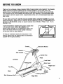
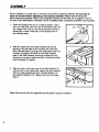
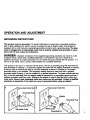
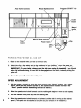
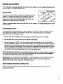
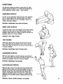
rPROGRAMMABLE
.
/NCLINEJOUU/ I
Warranty
Assembly
Operation
and Adjustment
Maintenance
and Storage
Conditioning
Guidelines
Ordering
Replacement
Parts.
i
I Serial
odel No.
No. 831.296570
i
OWNER'S
MANUAL
CAUTION:
Part
No. 046304
Read all instruotionsP_refullybeforeusing this product. Retain this Owner's Manual for referenoe.
12/89
SOLD BY SEARS,
ROEBUCK
AND CO.,
CHICAGO,
IL 60684
Copyright
© 1989 SEARS,
WARNING:
This is sspeclally
2
.efo,,
Important
ROEBUCK
beginning
AND CO.
this or any exercise
for individuals
program
consult
over the age of 35 or persons
health problems.
Reed all Instructions
before
personal
Injury or property damaae sustained
your physician.
with pre-existing
using. Sears assumes no responsibility
for
bv or throuah the uRe of thlA RAnrR nrnrl.nt
rPROGRAMMABLE
OI'It'I
.
INCLINEOOUU/#I
TABLE OF CONTENTS
Warranty
Safety Precautions
Before You Begin
Assembly
Operation and Adjustment
Maintenance and Storage
Conditioning Guidelines
Part List
3
4
5
6
7
10
11
14
Exploded Drawing
Ordering Replacement
15
16
I
Parts
FULL 90 DAY WARRANTY ON PARTS
I
For 90 days from the date of purchase, when proper assembly and maintenance procedures
detailed in the Owner's Manual are followed, Sears will, free of charge, repair or replace and
install a replacement part for any defective part, when the Programmable Incline Treadmill is used
in a normal manner.
This warranty does not apply when the Programmable Incline Treadmill is used for commercial or
rental purposes.
SERVICE IS AVAILABLE BY SIMPLY CONTACTING
CENTER/DEPARTMENT
IN THE UNITED STATES.
YOUR NEAREST SEARS SERVICE
This warranty gives you specific legal rights, and you may also have other rights which vary from
state to state.
SEARS, ROEBUCK AND CO., DEPT. 7$1CR-W, CHICAGO,
IL 60684
3
IMPORTANT
WARNING:
the following
1. Position
behind
SAFETY PRECAUTIONS
TO reduce
important
safety
the treadmill
the risk of burns,
precautions
on a clear,
the treadmill.
fire, electric
and information
level surface
shock
or injury
before
operating
with a minimum
Do not place the treadmill
to persons,
read
the treadmill.
of 8 feet of clearance
on thick carpet,
near water
or outdoors.
2. Plug the power cord diractly into a grounded circuit
carrying 12 or more amps. No other
appliance should be on the same circuit. (See the OPERATION
section of this manual for
proper grounding
Instructions.)
Keep the power cord away from heated surfaces.
If an
extension cord is required, use only a 14-gauge,
general-purpose
cord of six to ten feet
in length with a three-wire
conductor.
3. Never operate the treadmill if the cord or plug are damaged,
working properly. (Refer to the BEFORE YOU BEGIN section
Instructions
if the traadmill is not working properly.)
or if the treadmill is not
of this manual for
4. Never start the treadmill while you are standing on the walking
handrail when walking or running on the treadmill.
5. Keep small children
unattended
while
away from
the treadmill
during
operation.
belt.
Never
Always
hold the
leave the treadmill
it is running.
6. Always wear appropriate
clothing when using the treadmill.
Do not wear flowing clothing
that could become caught in the treadmill. Always wear running or aerobic shoes. Never
use the treadmill with bare feet, wearing only stockings,
or in sandals. Athletic support
clothes are also recommended
for both men and women.
7. Never
drop or Insert
8. Do not operate
administered.
9. Use this traadmill
10.
where
any object
aerosol
into any opening.
(spray)
only as described
products
are being
used or where
oxygen
is being
in this manual.
Always unplug the power cord before performing
cedures described
in this manual. Never remove
the maintenance
and adjustment
the motor hood unless Instructed
proto do
so by an authorized
service reprasentative.
Servicing other than the procedures
described in this manual should be performed
by an authorized
service representative
only.
SAVE THESE INSTRUCTIONS.
4
BEFORE YOU BEGIN
Thank you for purchasing a Sears Lifestyler 3800pi Programmable Incline treadmill. The Lifestyler
3800pi combines advanced engineering with innovative design to let you enjoy one of the
premier forms of cardiovascular exercise at your convenience, in the privacy of your own home.
Your workouts will be more enjoyable and effective with such features as a card-activated safety
power switch, electronic speed control, programmable incline and a microprocessor-based exercise monitor.
For your safety and benefit, read this manual carefully before using the treadmill.
If you have
additional questions, please call' our Customer Service Department toll-free at 1-800-999-3756,
(in
Canada at 1-800-824-8949),
during our regular business hours: Monday - Friday, 6 a.m. - 6 p.m.
Mountain Time.
In all correspondence
regarding
this product, please refer
to the product model number (831.296570),
and
serial number (recorded on an identification plate on the
front of the frame). Write the serial number in the box
on the front cover for easy reference.
To helpyou understand clearly the instructions in this
manual, please study the drawing below and familiarize
yourself with the parts identified.
Console
Monitor
Side Handrail
ht Post
Front
Left Side
Lock Knob
Walking
Belt
Motor
Hood
Power Cord
Foot Rail
Circuit
Breaker
Back
"Walking
Belt Adjustment
Bolt
Platform
Right Side
5
ASSEMBLY
Set the treadmill
in a clear area on the floor and remove all packing
materials.
Be sure that all
parts are Included before disposing of the packing materials.
Please read all instructions
before beginning assembly. Refer to the Exploded Drawing and the Part List on pages 14 and 15
for help in part identification.' Assembly can be completed using a standard screwdriver (not included).
.
Raise the Upright Post (27) to a vertical position. Insert
the Lock Knob (29), with the Lock Knob Washer (28), into
the Upright Post, and turn the Knob clockwise until it is
almost tight. Leave a little play in the Upright Post for
the following steps.
,
Slide the upper end of the Side Handrail (2) into the
opening in the left side of the Console (10). Insert the
Short Handrail Bolt (3) through the metal plate under the
Console, and tighten the Bolt into the Side Handrail.
Note: If the Side Handrail cannot be inserted into the
Console far enough to attach the Bolt, roll back the Side
Foam Handgrip (1) slightly.
.
Align the hole in the lower end of the Side Handrail (2)
with the hole in the Frame (52). Attach the Side Handrail
with the Long Handrail Bolt (73), Formed Washer (74)
and Handrail Washer (71). Tighten the Lock Knob (see
step 1).
Make sure that all parts are tightened
6
securely
before using the treadmill.
OPERATION AND ADJUSTMENT
GROUNDING
INSTRUCTIONS
This product must be grounded.
If it should malfunction or break down, grounding provides a
path of least resistance for electric current to reduce the risk of electric shock. This product is
equipped with a cord having an equipment-grounding
conductor and a'grounding
plug. The plug
must be plugged into an appropriste
outlet that is properly Installed and grounded
in accordance with all local codes and ordinances.
DANGER:
Improper connection of the equipment-grounding
of electric shock. Check with a qualified electrician or serviceman
conductor can result in a risk
if you are in doubt as to
whemer me proauct is properly grounded. Do not modify the plug provided with the product - if it
will not fit the outlet, have a proper outlet installed by a qualified electrician.
This product is for use on a nominal 120-volt circuit, and has a grounding plug that looks like the
plug illustrated in Drawing 1. A temporary adapter that looks like the adapter illustrated in Drawing
2 may be used to connect this plug to a 2-pole receptacle as shown in Drawing 2 if a properly
grounded outlet is not available. The temporary adapter should be used only until a properly
grounded outlet (Drawing 1) can be installed by a qualified electrician. The green colored rigid ear,
lug, or the like extending from the adapter must be connected to 8 permanent ground such as a
properly grounded outlet box cover. Whenever the adapter is used it must be held in place by a
metal screw. Some 2-pole receptacle outlet box covers are not grounded. Contact a qualified
electrician to determine If the outlet box cover is grounded before using an adapter.
1
Grounded
Outlet Box
2
Grounded
Outlet Box
i
Adapter
V
_rbunded
Outlet
7
Auto Incline Controls
Manual Speed Control
Program "START"
Key
Incline
O
Timer
Control
Manual
Manual
Incline
Control
Mode
Power Switch
TURNING
1.
THE POWER
Stand on the treadmill
.
3.
[_,
' '
_.__
_3
lip
ON AND OFF
with your feet on the foot rails.
Attach the clip on the safety card to the waistband of your clothing. To turn the power on,
insert the card into the power switch. The manual mode indicator above the switch will light.
IMPORTANT:
For your safety, always wear the clip when using the treadmill.
If you should
slip or fall while exercising, the card will be disengaged from the switch, instantly turning the
power off.
To turn the power off, remove the safety card.
SPEED ADJUSTMENT
1.
After the power is turned on, move the speed control to the "Reset"
position. (As a safety
feature, each time the power is turned on, the speed control must be moved to the
"Reset"
position before the walking belt can be started.)
,
8
Move the speed control slowly forward until the walking belt begins to move at slow speed.
3.
Hold the handrail firmly and step onto the walking belt,
4.
Move the speed control slowly forward or backward until the belt is moving at the desired
speed. (The speed can be adjusted at any time as you exercise on the treadmill.)
INCLINE
ADJUSTMENT
To vary the level of exercise difficulty, the incline of the treadmill
manual mode or the programmable
mode.
MANUAL
can be changed
using either the
MODE
The manual incline control is located on the right side of the
console. To increase the incline of the treadmill, press the
front of the control until the desired angle is reached. To
decrease the incline of the treadmill, press the back of the
control until the desired angle is reached.
There is a bubble located
of the treadmill.
PROGRAMMABLE
above the incline lever on the console.
The bubble measures
the incline
MODE
The programmable mode allows you to set the length of time that you plan to exercise, and program eight incline settings. The treadmill computer then controls the. incline of the treadmill
automatically for the set length of time.
1.
Set the timer for the length of time that you plan to exercise,
2.
Set the eight auto incline controls to the desired
.
from 5 to 40 minutes.
incline levels.
Press the program "START"
key. The indicator below the first auto incline control will light
and the treadmill will adjust to the first incline setting. After one-eighth of the total set time has
elapsed, the indicator below the second auto incline control will light and the treadmill will adjust to the secQnd incline setting. (The computer will sequentially activate all eight auto incline
controls regardless of the length of time set.) When the total time has elapsed, the treadmill
will remain at the last incline setting and revert to the manual mode.
Note: The auto incline controls can be changed while the program is running if desired. Pressing
the manual incline control at any time while the program is running will stop the program
and cause the treadmill to revert to the manual mode.
IMPORTANT:
This treadmill has been designed to remain operational if the electronic monitor or
programmable mode malfunction. Even with the monitor removed, the power, speed and
manual incline mode can be controlled as described above.
ELECTRONIC
MONITOR
Refer to the ELECTRONIC
operating instructions.
OPERATION
MONITOR
OPERATION
GUIDE
accompanying
this manual for
9
MAINTENANCE
AND STORAGE
Check all parts periodically to ensure that they are tightened securely. Outside surfaces of the
treadmill can be cleaned using a damp cloth and mild, non-abrasive detergent.
WALKING
BELT ADJUSTMENT
To prevent damage to the Walking Belt, always keep the Belt centered during operation. Stand
beside the treadmill and turn the treadmill on at medium speed. Observe the spaces between the
edges of the Walking Belt and the Foot Rails. If the Belt is closer to one Foot Rail than the other,
center the Belt in the following manner:
1.
Locate the Belt Adjustment
from the moving Walking
Bolts and the Adjustment Tool. Caution:
Belt or serious Injury could result.
2.
A.
If the Walking Belt has shifted to the left side:
Turn the left Adjustment Bolt clockwise and the
right Adjustment Bolt counterclockwise,
118 of a
turn at a time, until the Belt moves to the center.
B,
If the Walking Belt has shifted to the right side:
Turn the left Adjustment Bolt counterclockwise
and
the right Adjustment Bolt clockwise. 118 of a turn
at a time, until the Belt moves to the center.
Keep your hands
away
If the Walking Belt slips during operation, the tension
should be adjusted. Turn both Adjustment Bolts clockwise
an equal amount until the Belt no longer slips. Be careful
to keep the Belt centered. Do not over-tighten
the Bolts.
Overtightening
may stretch the Belt, cause excessive Roller
noise and reduce Motor performance.
To check for proper Walking Belt tightness, unplug the
Power Cord and lift the sides of the Belt. You should be able
to lift both sides approximately 2-3 inches off of the Walking
Platform. The center of the Belt should remain just at the
surface of the platform, causing the Belt to bow.
The Adjustment Tool can be stored on one of the Roller
Brackets using the adhesive Tool Clamp included.
Roller Bracket I
__
J
Clamp
10
SILICONE
APPLICATION
To maintain the low-friction quality of the Walking Belt and
reduce treadmill wear, a non-oil, non-petroleum
base
silicone
lubricant should be applied
generously
to the
Walking Platform.
(Silicone lubricant is available at most
hardware and automotive stores.) It is very Important
to
apply silicone lubricant before initial use of the treadmill.
Lubricant should also be applied after every 10 hours of use
or whenever a decrease in performance is noticed. Unplug
the Power Cord, lift each side of the Walking Belt and apply
the lubricant generously to the area indicated in the drawing.
CIRCUIT
BREAKER
If the treadmill stops or will not start, check the Circuit
Breaker located on the front of the Frame near the Power
Cord. The Circuit Breaker is designed to protect the
electrical system. If the Circuit Breaker has tripped, the
switch will protrude as shown. To reset the Circuit Breaker,
allow the treadmill to cool for a few minutes and then push
the switch back in.
Tripped
Operational
STORAGE
A0.,o,,o ,,.,,,,,,.
I.l,l_.._:p
• ,o_u_.Mjr.._
,h,_
Power Cord
,.,h=.,
,h,.
,._,.4,.,;.
Ltev
=
wu0e_.ooo
e.0l_,
L|_.*t._4III|e0
;.. nct in use. Tc convert the tr6admill
e_.#
to th6
storage position,
first remove the Bolts and Washers from the lower and upper ends of the
Handrail. Store the Bolts and Washers in a secure location. Loosen the Lock Knob and lay the
Upright Post on the treadmill.
Lay the Handrail on the treadmill.
The treadmill can be-moved by lifting the back end of the Frame
machine on the front Wheels.
CONDITIONING
and pushing or pulling the
GUIDELINES
The following guidelines will help you to plan and regulate your personal fitness program.
However,
before beginning
this or any exercise program, consult your physician.
Remember
that adequate rest and good nutrition are also essential to the success of any fitness program.
EXERCISE INTENSITY
To maximize health benefits from exercising, your level of exertion must exceed mild demands
while falling short of causing breathlessness and fatigue. The proper level of exertion can be
determined using the heart rate as a guide. For effective aerobic exercise the heart rate must be
maintained
Zone."
at a level between
70%
and 85% of your maximum
heart rate. This is your "Training
11
You can determine your Training Zone by consulting the table below. Training Zones are given for
both conditioned and unconditioned persons. Use the column that is appropriate for you.
UNCONDITIONED
TRAINING
ZONE
CONDITIONED
TRAINING
UNCONDITIONED
ZONE
TRAINING
ZONE
CONDITIONEO
TRAINING
ZONE
AGE
(BEATSIMIN)
(BEATS/MIN)
AGE
(BEATS/MIN)
(BEATS/MIN)
20
138-167
133-162
55
127-155
122-149
25
136-166
132-160
60
126-153
121-147
30
135-164
130-158
65
125-151
119-145
35
134-162
129-156
70
123-150
118-144
40
132-161
127-155
75
122-147
117-142
45
131-159
125-153
80
120-146
115-140
50
129-156
124-150
85
118-144
114-139
During the first few weeks of your exercise program you should keep your heart rate near the low
end of your Training Zone. Over the course of a few months, gradually increase your heart rate
until you reach the high end of your Training Zone. As your condition improves, a greater
workload will be required in order to raise your heart rate to your Training Zone.
You can measure your heart rate and find the proper level of exercise intensity using the electronic monitor (see the ELECTRONIC
MONITOR
OPERATION
GUIDE). First, set the monitor for 4
minutuu. FreEs the "STAR ,_'STOF" key and exercise ut a c;umfuriubiu pucu urdi; tile 4 minutu=_
elapse. Immediately measure your heart rate using the PULSE function.
If your heart rate is below
your Training Zone, increase your level of exertion. If your heart rate is too high, reduce your level
of exertion.
EXERCISE
PATTERN
Each workout should consist of a basic 5-step pattern.
1. Arrest
2. Warm-up
3. Training Zone exercise
4. Cool-down
5. At rest
Warming up is an important part of your workout and should not be taken lightly. Warming up
prepares the body for more strenuous exercise by increasing the circulation, delivering more
oxygen to the muscles, and raising the body temperature. This can be done by stretching and
light calisthenics for 5-10 minutes prior to exercising.
Begin exercising at a light pace for a few minutes. Then increase
rate to your Training Zone for a period of 20-30 minutes.
the intensity to raise your heart
Cooling down after vigorous exercise is important in aiding circulation and preventing
5-10 minutes of light exercise or stretching will allow the body to cool down.
EXERCISE
soreness.
FREQUENCY
To maintain or improve your condition you must work out 2-3 times per week following the pattern
described above. A day of rest between workouts is recommended.
After several months of exercise the number of workouts can be increased to 4-5 times per week. The key to a successful pro12
gram is REGUI_AR
EXERCISE.
STRETCHING
The following stretches provide a good warm-up. Each
position should be held for 15 counts and performed for
three repetitions. Stretch slowly -- don't bounce.
HAMSTRING
Sit with
foot in,
Stretch
counts,
STRETCH
one leg extended. Bring the sole of the opposite
resting against the extended leg's inner thigh.
toward your toe as far as possible. Hold for 15
then relax. Repeat.
Stretches:
Hamstrings,
INNER THIGH
lower
back
and groin.
STRETCH
Sit with the soles of your feet together and knees pointing
outward. Pull your feet as close into the .groin area as
possible. Gently push your knees as close to the floor as
possible. Hold for 15 counts. Repeat.
Stretches:
Inner thigh
muscles.
TOE TOUCHES
With knees slightly bent, slowly bend forward from the
hips. Allow back and shoulders to relax as you stretch
toward your toes. Go down as far as you can and hold for
15 counts. Repeat.
Stretches:
Hamstrings,
QUADRICEPS
back of knees,
back.
STRETCH
With one hand against a wall for balance, reach behind
you and pull up your foot. Bring your heel as close to your
buttocks as possible. Hold for 15 counts. Repeat.
Stretches: Quadriceps,
CALF/ACHILLES
hip muscles.
STRETCH
With one leg in front of the other and arms forward, lean
against the wall. Keep your back leg straight and back
foot flat on the floor; then bend the front leg and lean forward by moving your hips toward the wall. Hold, then
Irepeat on the other side for 15 counts. To cause further
stretching of the achilles tendons, slightly bend back leg
as well.
Stretches:
Calves,
achilles
tendons,
and ankles.
13
PART LIST-
14
Model No. 831.296570
Rev z,89
Key
No.
Reorder
No.
Qty.
Side Foam Handgrip
Side Handrail
Handrail Bolt
48
013501
2
Wheel
49
50
013561
010203
2
2
Lift Frame Bolt
Foot Rail
1
6
Foam Handgrip
Console Screw
51
52
040218
NSP
1
1
Safety Cover
Frame
009157
017096
032083
017094
033187
1
1
1
9
1
Console Assembly
Manual Control Knob
Electronic Monitor
Auto Control Knob
Auto Incline Console
53
54
55
56
57
053031
040156
008195
013206
070084
1
2
1
2
1
Walking Platform
Rear Leg Endcap
Right Roller Bracket
Rear Roller Adj. Bolt
Rear Roller
11
12
13
14
15
033007
054013
070843
013551
088015
1
1
1
2
1
Pulse Ear Clip
Clothes Clip
Safety Card/Clip
Monitor Screw
Incline Bubble
58
59
60
016028
045010
008194
1
1
1
Tool Clamp
Adjustment
Tool
Left Roller Bracket
61
62
025060
.013511
1
4
Walking Belt
Motor Hood Screw
16
17
18
19
20
21
020050
021046
031226
030049
031237
013391
1
1
1
1
1
4
Motor Pulley
Flywheel
Fan
Motor
Motor Connect
Motor Bolt
63
64
65
022052
019190
016050
1
1
1
Front Roller/Pulley
Front Roller Bushing
Roller Lock
66
67
013300
025064
1
1
Reed Switch
V-Belt
68
016055
4
Sensor
23
24
031173
013162
1
19
Motor Controller
Small Screw
70
71
009126
014086
1
1
Motor Hood
Handrail Washer
25
26
27
28
29
30
31
32
33
34
35
36
37
38
013485
014132
007096
014156
017088
031199
031103
012149
014157
031229
013578
014086
030016
012025
1
2
1
1
1
1
1
3
1
1
1
2
1
2
Hinge Bolt
Hinge Washer
Upright Post
Lock Knob Washer
Lock Knob
Switch Wire
Circuit Breaker
Lock Nut
Star Washer
Power Cord
Incline Motor Bolt
Incline Motor Washer
Incline Motor
Incline Motor Nut
72
73
74
75
040132
013460
014094
031249
1
1
1
1
Handrail Cap
Long Handrail Bolt
Formed Washer
Auto Incline Wire
76
77
78
79
033066
015071
012137
008257
1
3
2
1
Sensor Magnet
Clip Pin
Push Nut
Lift Board Arm
80
81
82
83
008258
015072
031220
008297
1
2
1
1
Linkage Arm
Plastic Pin
Lift Board
L-Bracket
39
40
41
42
43
013275
014063
040119
012082
014041
1
3
1
4
4
Front Roller Adj. Bolt
Adjustment Washer
Handlebar Endcap
Motor Locknut
Flat Washer
84
85
86
87
031196
031197
019084
041043
1
2
1
4
Manual Incline Wire
Small Lift Wire
Grommet
Hood Cushion
44
45
46
47
013494
012173
004224
052014
6
2
1
2
Large Screw
U-Nut
Lift Frame
Front Wheel
88
89
#
#
019183
013284
046304
089036
2
2
1
1
Leg Bumper
Controller
Mtg. Screw
Owner's Manual
Electronic Monitor Guide
Key
No.
Reorder
No.
1
2
3
041068
003069
013522
1
1
1
4
5
041042
013322
6
7
8
9
10
Qty.
Descrlptlon
Wire
Note: "#"
See the back cover of this manual for part ordering information.
Description
Bolt
Wire
Mtg. Screw
Clip
indicates a non-illustrated part.
EXPLODED DRAWING.
*Specifications
are subject to change
Model No. 831.296570
Rev. 12/89
without notice.
9
10
4
12
5
5
15
14
18
2O
73
71
29
>
70
25
26
62
24
66
_.0::".38
37
I
I
I
i
63
I
i
I
i
40
5O
39
!47
38
61
\
6O
44
52
51
53
54
56
59
57
56
55
/
24-
83
82
78
15
SEAFIIS ®SERVICE is at YOUR SER VICE
ORDERING REPLACEMENT
Each TREADMILL
has its own MODEL
Always mention this
TREADMILL.
MODEL
NUMBER
PARTS
NUMBER.
when requesting
P,!t r"""*"
""*"_ h,_,.,_;,.,,m:y .....
h,,, .............
,-,,,4,.,,,.,,,4,_ .... _,..,h
SEARS
..................
...........
and most Sears Retail Stores.
service or repair parts for your
D_"-_l
I¢'VZ..............
^_.ln r'_ " SERVICE
If parts you need are not stocked locally, your order will be electronically
PARTS DISTRIBUTION
CENTER for expedited handling.
WHEN
ORDERING
1. The MODEL
REPAIR
NUMBER
PARTS,
OF THE
ALWAYS
PRODUCT
GIVE
THE
FOLLOWING
transmitted
.
OF THE
The SERIAL
PRODUCT
NUMBER
(Lifestyler
to a SEARS
INFORMATION:
(831.296570).
Serial
2. The NAME
r"=_iT_D_
_' "
3800pi treadmill).
found on the treadmill
No.
•
II
identification
plate (see the drawing to the right). Write the number in the
box for easy reference.
4. The KEY NUMBER
this manual.
OF THE
5. The PART DESCRIPTION
PART from the Part List found in
from the Part List found in this manual.
Front of treadmill
Your Sears merchandise has added value when you consider that Sears has service units
nationwide staffed with Sears trained technicians specifically trained on Sears products, having the
parts, tools and the equipment to insure that we meet our pledge to you:'we service what we sell.
SOLD BY SEARS,
16
Part No. 046304
12/89
ROEBUCK
AND CO., CHICAGO,
IL 60684
Printed in U.S.A.