1
Owner's Manual
I (RRFTSMRN1
WIRE FEED MIG WELDER
Model No.
196.205680
/
CAUTION: Before using this
product, read this manual and
follow all its Safety Rules and
Operating Instructions.
Sears, Roebuck and Co., Hoffman
www.sears.com/craftsman
Estates,
EspaSol p.27
IL 60179
U.S.A.
Craftsman
Limited Warranty ............
Table Of Contents ..............................
Safety Summary ................................
Important
Safety Information
........
Shock Hazards ..............................
Flash Hazards ................................
Fire Hazards ..................................
Fume Hazards ................................
Additional Safety Information ..........
Know Your Welder
............................
Assembly
............................................
Unpacking the Welder ......................
Packing List ......................................
Installing the Handle ........................
Assemble the Face Shield ................
Power Source Connection ................
Extension Cords ..............................
2
2
3
3
4
4
5
6
7
8
9
9
9
9
9
9
10
Selecting the Welding Wire ..............
Install the Welding Wire ....................
Operation
............................................
Description ........................................
Duty Cycle ........................................
Internal Thermal Protection ..............
Controls and Indicators ....................
Preparations
for Welding ..................
Setting Up the Work Piece ..............
Preparing the Joint ............................
Ground Clamp Connection
..............
Learning to Weld ..............................
Holding the Gun ................................
Position the Gun to
the Work Piece ............................
Distance From the Work Piece ......
10
10
11
11
11
12
12
12
12
12
13
14
14
Laying a Bead ..................................
Welding Techniques ..........................
Traveling the Gun ..........................
Types of Weld Beads ....................
Welding Positions ..........................
Multiple Pass Welding ....................
Special Welding Methods ................
Spot Welding ....................................
Spot Welding Instructions
..............
Maintenance
......................................
General Maintenance
......................
Consumable
Maintenance ..............
Maintaining the Contact Tip ............
Testing for a Shorted Nozzle ..........
Replace a Gun Liner ........................
Maintaining the Welder ....................
Troubleshooting
................................
Parts List ............................................
Wiring Diagram ..................................
Suggested
Settings ..........................
15
15
15
15
16
17
17
17
18
18
18
18
18
19
19
20
20
22
25
26
2
14
14
Limited
Welder
Three-Year
Warranty
on Craftsman
For three years from the date of purchase, if
any part of this welder, except for the gun or
cables, fails due to a defect in material or
workmanship,
return it to your nearest Sears
Parts & Repair Center, and it will be repaired
free of charge. Sears will repair the gun or
cables free of charge for only one year from
the date of purchase. This warranty does not
cover expendable
parts such as contact tips
or nozzles, which are consumed during normal welder operation. This warranty applies
only while this product is used in the United
States. This warranty gives you specific legal
rights, and you may also have other rights
which vary from state to state.
Sears, Roebuck and Co., D/817WA,
Estates, IL 60179
Hoffman
Note:
Every craftsmanrespectsthe tools with
which they work. They knowthat the tools
The following safety alert symbols
identify important safety messages
manual.
represent years of constantly improved
designs and developments.
The true craftsman also knows that tools are dangerous if
misused or abused.
When you see one of the symbols
shown here, be alert to the possibility of
personal injury and carefully read the
message that follows.
_']
Reading this operator's
manual before using
the welder will enable you to do a better,
safer job. Learn the welder's applications
and limitations as well as the specific potential hazards peculiar to welding.
•_J
indicates
that the
I possibility of electric shock hazard
I exists during the operation of the
step(s)
that follow.
This symbol indicates that the
possibility of fire hazard exists
during the operation of the step(s)
that follow.
IMPORTANT
SAFETY
INFORMATION
The following safety information is provided
as guidelines to help you operate your new
welder under the safest possible conditions.
Any equipment that uses electrical power
can be potentially dangerous to use when
safety or safe handling instructions
are not
known or not followed. The following safety
information is provided to give the user the
information necessary for safe use and
operation.
A procedure step preceded by a
WARNING
is an indication that the next step
contains a procedure that might be injurious
to a person if proper safety precautions
are
not heeded.
A procedure preceded by a CAUTION
is an
indication that the next step contains a
procedure that might damage the equipment
being used.
A NOTE may be used before or after a procedure step to highlight or explain something
in that step.
READ ALL SAFETY INSTRUCTIONS
CAREFULLY
before attempting to install,
operate, or service this welder. Failure to
comply with these instructions could
result in personal injury and/or property damage.
RETAIN THESE INSTRUCTIONS
FUTURE REFERENCE.
,,_ Ii'
This symbol
in this
This symbol indicates that the
helmet must be worn during the
step(s) that follow to protect
against eye damage and burns
due to flash hazard.
This symbol indicates that the
possibility of toxic gas hazard
exists during operation of the
step(s) that follow.
This symbol indicates that the
possibility of being burned by hot
slag exists during operation of the
step(s) that follow.
This symbol indicates that the eye
protection should be worn to
protect against flying debris in the
following step(s).
Published standards on safety are
available. They are listed in ADDITIONAL
SAFETY INFORMATION
at the end of
this SAFETY SUMMARY.
The National Electrical Code, Occupation
Safety and Health Act regulations, local
industrial codes and local inspection
requirements
also provide a basis for
equipment installation,
use, and service.
FOR
3
SHOCK
HAZARDS
Do not alter power cord or power cord
plug in any way.
Do not attempt to plug the welder
into the power source if the ground prong
on power cord plug is bent over, broken
off, or missing.
Do not allow the welder to be connected
I.__ ]WARN' O
ELECTRIC
SHOCK
CAN KILL!
To reduce
to the power source or attempt to weld if
the welder, welding cables, welding site,
or welder power cord are exposed to any
form of atmospheric
precipitation,
or salt
water spray.
Do not carry coiled welding cables around
shoulders, or any other part of the body,
when they are plugged into the welder.
Do not modify any wiring, ground
connections,
switches, or fuses in
this welding equipment.
Wear welding gloves to help insulate
hands from welding circuit.
Keep all liquid containers far enough
away from the welder and work area so
that if spilled, the liquid can not possibly
come in contact with any part of the
welder or electrical welding circuit.
Replace any cracked or damaged parts
that are insulated or act as
insulators such as welding cables, power
cord, or electrode holder
IMMEDIATELY.
the risk of death or serious injury from shock,
read, understand,
and follow the following
safety instructions.
In addition, make certain
that anyone else who uses this welding
equipment,
or who is a bystander in the
welding area understands
and follows these
safety instructions as well.
IMPORTANT!
TO REDUCE THE RISK
OF DEATH, INJURY, OR PROPERTY
DAMAGE, DO NOT ATTEMPT
OPERATION
of this welding equipment
until you have read and understand the
following safety summary.
Do not, in any manner, come into physical
contact with any part of the welding
current circuit. The welding current circuit
includes:
a. the work piece or any conductive
material in contact with it,
b. the ground clamp,
c. the electrode or welding wire,
d. any metal parts on the electrode
holder, or wire feed gun.
Do not weld in a damp area or come in
contact with a moist or wet surface.
Do not attempt to weld if any part of
clothing or body is wet.
Do not allow the welding equipment
to come in contact with water or
moisture.
Do not drag welding cables, wire feed
gun, or welder power cord through or
allow them to come into contact with
water or moisture.
Do not touch welder, attempt to turn
welder on or off if any part of the
body or clothing is moist or if you
are in physical contact with water or
moisture.
4
Do not attempt to plug
into the power source
or clothing is moist, or
are in physical contact
or moisture.
the welder
if any part of body
if you
with water
Do not connect welder
to or weld on electrical
work piece clamp
conduit.
FLASH
HAZARDS
_p]
WARNING
ARC RAYS CAN INJURE EYES AND BURN
SKIN! To reduce the risk of injury from arc
rays, read, understand, and follow the following
safety instructions. In addition, make certain
that anyone else that uses this welding
equipment, or is a bystander in the welding
area understands and follows these safety
instructions as well. Headshields and filter
should conform to ANSI Z87.1 standards.
Do not look at an electric
arc without
proper protection. A welding arc is
extremely bright and intense and, with
inadequate or no eye protection, the
retina can be burned, leaving a
permanent dark spot in the field of vision.
A shieldor helmetwith a number10
shade filter lens (minimum)mustbe used.
Do not strike a welding arc untilall
bystandersand you (the welder)
haveweldingshieldsand/orhelmets
in place.
Do not wear a crackedor broken
helmetand replaceany crackedor
brokenfilter lenses IMMEDIATELY.
Do not allow the uninsulatedportion
of the wire feed gun to touchthe ground
clampor groundedwork to preventan arc
flash from beingcreatedon contact.
Providebystanderswith shieldsor helmetsfitted with a #10 shadefilter lens.
Wear protectiveclothing.The intenselight
of the welding arc can burnthe skin in
muchthe sameway as the sun, even
through light-weightclothing.Wear dark
clothingof heavymaterial.The shirt worn
should be long sleevedand the collar
kept buttonedto protect chestand neck.
Protectagainst REFLECTEDARC RAYS.
Arc rays can be reflectedoff shiny
surfacessuch as a glossy painted
surface,aluminum,stainlesssteel,and
glass. It is possiblefor your eyesto be
injuredby reflectedarc rays evenwhen
wearinga protectivehelmetor shield. If
weldingwith a reflectivesurfacebehind
you, arc rays can bounceoff the surface,
then off the filter lens on the insideof
your helmetor shield,then into your eyes.
If a reflectivebackgroundexists in your
weldingarea, eitherremoveit or cover it
with somethingnon-flammableand nonreflective.Reflectivearc rays can also
causeskin burn in additionto eye injury.
FIRE HAZARDS
WARNING
FIRE OR EXPLOSION
CAN CAUSE
DEATH, INJURY, AND PROPERTY
DAMAGE! To reduce the risk of death, injury,
or property damage from fire or explosion,
read, understand,
and follow the following
safety instructions. In addition, make certain
that anyone else that uses this welding
equipment, or is a bystander in the welding
area, understands
and follows these safety
instructions as well. REMEMBER!
Arc welding by nature produces sparks, hot spatter,
molten metal drops, hot slag, and hot metal
parts that can start fires, burn skin, and
damage eyes.
Do not wear gloves or other
that contains oil, grease, or
flammable substances.
Do not wear flammable hair
preparations.
Do not weld in an area until
and cleared of combustible
clothing
other
it is checked
and/or flam-
mable materials. BE AWARE that sparks
and slag can fly 35 feet and can pass
through small cracks and openings. If
work and combustibles
cannot be separated by a minimum of 35 feet, protect
against ignition with suitable, snug-fitting,
fire resistant, covers or shields.
Do not weld on walls until checking for
and removing combustibles
touching the
other side of the walls.
Do not weld, cut, or perform other such
work on used barrels, drums, tanks, or
other containers that had contained a
flammable or toxic substance. The techniques for removing flammable
substance and vapors, to make a used
container safe for welding or cutting, are
quite complex and require special
education and training.
Do not strike an arc on a compressed
gas or air cylinder or other pressure vessel. Doing so will create a brittle area that
can result in a violent rupture
immediately
or at a later time as
a result of rough handling.
Do not weld or cut in an area where the
air may contain flammable dust (such as
grain dust), gas, or liquid vapors (such as
gasoline).
Do not handle hot metal, such as the
work piece or electrode stubs, with bare
hands.
Wear leather gloves, heavy long sleeve
shirt, cuffless trousers, high-topped
shoes, helmet, and cap. As necessary,
use additional protective clothing such as
leather jacket or sleeves, fire resistant
leggings, or apron. Hot sparks or metal
can lodge in rolled up sleeves, trouser
cuffs, or pockets. Sleeves and collars
should be kept buttoned and pockets
5
eliminated from the shirt front.
Have fire extinguisher equipment handy
for immediate use! A portable chemical
fire extinguisher,
type ABC, is
recommended.
Wear ear plugs when welding overhead
to prevent spatter or slag from falling
into ear.
Make sure welding area has a good,
solid, safe floor, preferably concrete or
masonry, not tiled, carpeted, or made of
any other flammable material.
Protect flammable walls, ceilings,
and floors with heat resistant covers
or shields.
Check welding area to make sure it
is free of sparks, glowing metal or slag,
and flames before leaving the welding
area.
FUME
HAZARDS
WARNING
FUMES, GASSES, AND VAPORS CAN
CAUSE DISCOMFORT,
ILLNESS, AND
DEATH! To reduce the risk of discomfort,
illness, or death, read, understand, and follow
the following safety instructions.
In addition,
make certain that anyone else that uses this
welding equipment or is a bystander in the
welding area, understands
and follows these
safety instructions as well.
Do not weld in an area until it is checked
for adequate ventilation as described in
ANSI standard #Z49.1. If ventilation is
not adequate to exchange all fumes and
gasses generated during the welding
process with fresh air, do not weld unless
you (the welder) and all bystanders are
wearing air-supplied respirators.
Do not heat metals coated with, or that
contain, materials that produce toxic
fumes (such as galvanized steel), unless
the coating is removed. Make certain the
area is well ventilated, and the operator
and all bystanders are wearing air-supplied respirators.
Do not weld, cut, or heat lead, zinc,
cadmium, mercury, beryllium, or similar
metals without seeking professional
6
advice and inspection of the ventilation of
the welding area. These metals produce
EXTREMELY
TOXIC fumes which can
cause discomfort,
illness, and death.
Do not weld or cut in areas that are near
chlorinated solvents. Vapors from chlorinated hydrocarbons,
such as
trichloroethylene
and perchloroethylene,
can be decomposed
by the heat of an
electric arc or its ultraviolet radiation.
These actions can cause PHOSGENE,
a
HIGHLY TOXIC gas to form, along with
other lung and eye-irritating
gasses. Do
not weld or cut where these solvent
vapors can be drawn into the work area
or where the ultraviolet radiation can pen
etrate to areas containing even very
small amounts of these vapors.
Do not weld in a confined area unless it
is being ventilated or the operator (and
anyone else in the area) is wearing an
air-supplied
respirator.
Stop welding if you develop momentary
eye, nose, or throat irritation as this indicates inadequate ventilation.
Stop work
and take necessary steps to improve
ventilation in the welding area. Do not
resume welding if physical discomfort
persists.
ADDITIONAL
SAFETY
INFORMATION
For additional information concerning
welding safety, refer to the following
standards and comply with them as
applicable.
ANSI Standard Z49.1
SAFETY IN
WELDING AND CUTTING - obtainable
from the American Welding Society, 550
NW Le Jeune Road, Miami, FL 33126
Telephone (800) 443-9353,
Fax (305) 443-7559 - www.amweld.org
or www.aws.org
ANSI Standard Z87.1 - SAFE PRACTICE FOR OCCUPATION
AND EDUCATIONAL EYE AND FACE PROTECTION
- obtainable from the American National
Standards
Institute, 11 West 42nd St.,
New York, NY 10036
Telephone (212) 642-4900,
Fax (212) 398-0023 - www.ansi.org
NFPA Standard 51B - CUTTING AND
WELDING
PROCESS - obtainable from
the National Fire Protection Association,
1 Batterymarch
Park, P.O. Box 9101,
Quincy, MA 02269-9101
Telephone (617) 770-3000
Fax (617) 770-0700 - www.nfpa.org
OSHA Standard 29 CFR, Part 1910,
Subpart Q., WELDING, CUTTING AND
BRAZING - obtainable from your state
OSHA office or U.S. Dept. of Labor
OSHA, Office of Public Affairs, Room
N3647, 200 Constitution
Ave.,
Washington,
DC 20210 - www.osha.gov
CSA Standard W117.2 - Code for SAFETY IN WELDING AND CUTTING. obtainable from Canadian Standards
Association,
178 Rexdale Blvd.,
Etobicoke, Ontario M9W 1R3 www.csa.ca
American Welding Society Standard
A6.0. WELDING AND CUTTING CONTAINERS WHICH HAVE HELD COMBUSTIBLES.
- obtainable from the
American Welding Society, 550 NW Le
Jeune Road, Miami, FL 33126
Telephone (800) 443-9353,
Fax (305) 443-7559 - www.amweld.org
or www.aws.org
7
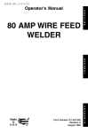
Power Cord - This is a standard, grounded
120 volt power cord. (Make sure you are
using a properly grounded 120 Vac, 60Hz,
single phase, 20 amp power source.)
Wire Speed
Handle
Gun Cable
Ground
Clamp - Attaching the ground
clamp to your work piece "completes" the
welding current circuit. You must attach the
ground clamp to the metal you are welding. If
the ground clamp is not connected to the
metal work piece you intend to weld, the
welder will not have a completed circuit and
you will be unable to weld. A poor connection
at the ground clamp will waste power and
heat. Scrape away dirt, rust, scale, oil or
paint before attaching the ground clamp.
Power
"Switch
J
Welding
Gun
Voltage
Selector
Figure
Clamp
Gr( und
Cable
Ground
Cable - The ground cable connects
the ground clamp to the internal workings of
the welder.
1. Model 20568 Welder
Handle - Rugged, top mounted handle
allows for easy transport of your welder.
Wire Speed Control - Use this dial to adjust
the speed at which the welder feeds wire to
the gun. 1 is the slowest wire feed speed, 10
is the highest. You will need to adjust or
"tune-in" your wire speed for different welding
conditions (thickness of metals, metal type,
wire size, etc.). When the wire speed is properly "tuned-in" the welding wire will melt into
the material you are welding as quickly as it is
fed through the welding gun.
Voltage Selector - This two position switch
adjusts the voltage or "heat" of your welder.
Select MIN setting for lower voltage and
MAX setting for higher voltage. Different
materials and material thickness will require
different voltage settings. You will need to
adjust your voltage accordingly for different
welding conditions.
By properly adjusting
your voltage settings and wire feed speed,
you will enable clean, precision welds. (Refer
to the Suggested Settings Chart on p.26 of
this manual OR on the inside of the door of
the welder.)
Power
Switch
- This switch turns the welder
ON and OFF. (Make sure the power switch
in the OFF position before performing any
maintenance
on the welder.)
8
is
Welding
Gun and Cable - The welding gun
controls the delivery of the welding wire to
the material to be welded. The welding wire
is fed through the welding cable and welding
gun when the welding gun trigger is pulled.
You will need to install a contact tip and
welding nozzle to the end of the welding gun,
as described later in this manual, prior to
welding.
Welding Terms -Now that you are familiar
with the main parts of the welder, make note
of the following terms. You will see them
used throughout
this manual.
weld puddle: The localized volume
of molten metal in a weld prior to its
solidification.
weld angle: The angle of the welding wire,
as it extends from the welding gun, in relation to the item being welded.
slag: The protective coating that forms on
the surface of molten metal.
arc: A sustained luminous discharge of electricity across a gap in a circuit.
welding
bead: The extended build up of a
weld, made by pushing or pulling the weld
puddle.
ASSEMBLE
THE
FACE
SHIELD
1.
Thefollowingproceduresdescribethe process
requiredto assemble,install,maintain,and prepareto weldwithyournewwirefeedac welder.
UNPACKING THE WELDER
1. Removeany cartonsor bagscontaining
parts/accessories.(Mostparts are
shippedinside the welderdoor.)
2. Openthecartonsor bagspackedwithyour
welderandinspecttheircontentsfordamage.
3. Layoutthe partsand comparethem to
the the packinglist in Table1 to
familiarizeyourselfwith the parts and
what they are called.This will help you
when readingthe manual.
Remove the lens retaining pegs and
shield handle nut from the arm of the
shield handle. (DO NOT DISCARD!)
2. Place the shaded lens into the space
provided on the inside of the face shield.
3. Screw the lens retaining nuts into the
holes to either side of the lens until they
are tight against lens.
4. Insert threaded peg on shield handle into
hole on face shield. Press firmly until
threaded peg and smaller peg below it
are locked into place.
5. From inside of shield, screw the shield
handle nut tightly onto peg threads.
See Figure 3 for face shield assembly.
PACKING
LIST
Table 1 contains a list of the items you will
find packed in the carton.
Table
1. Packing
ITEM
List
QTY.
Welder
Face Shield
Face Shield Handle
Handle Screws
Shaded Lens
Welder Handle
Wire Brush/Hammer
1
1
1
2
1
1
1
Parts Bag
Contact Tip 0.030
Contact Tip 0.040
Nozzle
1
5
5
2
Wire .030 Fluxcore
Manual, Instruction
Figure
POWER
(1/2lb.)
1
INSTALLING
THE HANDLE
1. Insert the tabs of the welder handle into
the slots provided on the top of the welder.
2. Insert a large flat head screw (included in
the accessories
bag) into each hole on
the top of the welder handle.
3. With a flat tip screwdriver,
securely
tighten both screws. (see Figure 2)
I
Figure
!
2. Handle
Installation
SOURCE
CONNECTION
High voltage danger from power source!
Consult a qualified electrician for proper
installation of receptacle at the power source.
This welder must be grounded while in
use to protect the operator from electrical
shock. If you are not sure if your outlet is
properly grounded, have it checked by a
qualified electrician. Do not cut off the
grounding prong or alter the plug in any
way and do not use any adapters
between the welder's power cord and the
power source receptacle.
Make sure the POWER
1
!
3. Face Shield Assembly
switch is OFF then
connect your welder's power cord to a properly
grounded 120 Vac, 60 Hz, single phase, 15
amp power source. Do not operate this welder
if the source voltage is less than 105 Vac or
greater than 132 Vac. Contact a qualified electrician if this problem exists. Improper performance and/or damage to the welder will result if
operated on inadequate or excessive power.
9
EXTENSION
CORDS
For optimum welder performance, an extension
cord should not be used unless absolutely
necessary. If necessary, care must be taken in
selecting an extension cord appropriate for use
with your specific welder.
through a hole in the outer edge of the
spool and is bent over the spool edge to
prevent the wire from unspooling) BUT
DO NOT UNHOOK IT YET.
.
Select a properly grounded extension cord
that will mate directly with the ac power
source receptacle and the welder power cord
without the use of adapters. Make certain that
the extension cord is properly wired and in
good electrical condition. Extension cords
must fit the following wire size guidelines:
0-25 ft. requires #12 gauge
Do not use an extension cord over
Place the spool on the spindle in such a
manner that when the wire comes off the
spool, it will look like the top illustration in
Figure 4.
25 ft. in length.
SELECTING
THE
WELDING
WIRE
This welder uses only four inch spools of
0.030 inch (0.8mm) or 0.035 inch (0.9mm)
self shielding flux-core wire. Steel from
18 gauge up to 3/16 inch thick can be
welded with this wire.
NOTE:
Metal thinner than 18 gauge cannot be
welded with this machine. Attempting to do so
will cause burn through (blowing holes) in the
metal you are intending to weld.
If a spool has developed heavy oxidation,
the only solution to the problem is to discard
the spool of wire.
If you have an oxidized spool of wire, do not
discard it until you have unspooled a few
turns of wire to see if the wire further down
on the spool is in usable
discard the spool.
INSTALL
condition,
THE WELDING
if not, -
WIRE
Electric shock can kill! Always turn the
POWER switch OFF and unplug the welder's
power cord from the ac power source before
installing wire.
1. Remove the nozzle and contact tip from
the end of the gun assembly.
2. Remove the spindle cap from spindle.
3. Unwrap the spool of wire and then find
the leading end of the wire (it goes
10
Wrong Way
Figure
4. Proper Wire Installation
5.
Insert the spool retaining tab into the
spool shaft. The tab will lock into place,
prohibiting the spool from coming loose
during operation.
6. Use a wire cutter, cut the bent end off the
leading end of the wire so that only a
straight leading end remains.
7. Hold the tension arm up off the drive
roller and insert the leading end of the
wire into the inlet guide tube. Then push
it across the drive roller and into the gun
assembly about six inches.
8. Line the wire up in the outside groove of
the drive roller, then allow the drive tension
arm to drop onto the drive roller.
9. Tighten (turn clockwise) the tension adjusting
screw until the tension roller is applying enough
force on the wire to prevent it from slipping out
of the drive assembly.
9. Let go of the wire.
10. Plug the welder's power cord into the ac
power source. Adjust the HEAT selection
switch, on the front of the welder, to either
of the two heat settings.
ARC RAYS CAN INJURE EYES!
To reduce the risk of arc flash, make certain
that the welding wire, when it finally comes
out of the end of the gun, does not touch the
ground clamp or any grounded piece of
metal. IMPORTANT!
The welding wire is carrying welding current whenever the welder is
turned on.
11. Pull the trigger on the welding gun to feed
the wire through the gun assembly.
12. When at least an inch of wire sticks out
past the end of the gun, release the trigger.
13. Install the supplied 0.030 inch (0.8mm)
size contact tip.
Note: Due to inherent variances in fluxcored welding wire, it may be necessary
to use a welding tip one size larger than
your flux-core wire if jams occur.
14. Slide the contact tip over the wire
(protruding from the end of the gun).
Screw the contact tip into the end of the
gun and hand tighten securely.
15. Install the nozzle on the gun assembly.
16. Cut off the excess wire that extends past
the end of the nozzle.
ARC RAYS CAN INJURE EYES!
To reduce the risk of arc flash, make certain
that the wire coming out of the end of the
gun does not come in contact with the
ground clamp or any grounded material during the drive tension setting process.
17. Set the wire drive tension.
a. Pull the trigger on the gun.
b. Turn the drive tension adjustment
knob clockwise, increasing the drive
tension until the wire seems to feed
smoothly without slipping.
Note: If TOO MUCH tension is applied, the
wire will slip on the drive roller or will not be
able to feed at all. If TOO LITTLE tension is
applied,
unspool
Your new MIG (Metal Inert Gas) Wire Feed
welder is designed for maintenance
and
sheet metal fabrication.
The welder consists
of a single-phase
power transformer,
and a
unique built-in control/feeder.
This welder is
capable of welding with 0.030 inch
self-shielding
flux-core wire.
Now you can weld 18 gauge sheet metal up
to 3/16 inch with a single pass. You can weld
1/4 inch steel with beveling and multiple pass
techniques.
Table 2 lists your wire feed
welder specifications.
Table 2. Welder
Primary (input) volts
120 Vac
Welding Range
60-120 Amps
Primary (inputs) Amps
20
Phase
Single
Frequency
60 Hz
Secondary (output) volts
17
Secondary
(output) amps
80
Duty Cycle Rating at 80 amps
20%
Open Circuit Volts/Max.!
DUTY
along the wire feed path, the wire should
then slip on the drive roller.
25 Vac
CYCLE
The duty cycle rating of a welder defines how
long the operator can weld and how long the
welder must be rested and cooled. Duty cycle
is expressed as a percentage of 10 minutes
and represents the maximum welding time
allowed. The balance of the 10 minute cycle is
required for cooling.
Your new welder has a duty cycle rating of
20% at the CSA rated output of 80 amps. This
means that you can weld for two (2) minutes
out of 10 with the remaining eight (8) minutes
required for cooling. (See Table 3.)
the spool of wire will want to
itself.
When the drive tension is set correctly, there
should be no slippage between the wire and
the drive roller. But if an obstruction
occurs
Specifications
Table
Duty
Cycle
Rating
20%
40%
60%
80%
100%
3. Duty Cycle Ratings
Maximum
Welding
Time
2 minutes
4 minutes
6 minutes
8 minutes
10 minutes
Required
Resting
Time
8 minutes
6 minutes
4 minutes
2 minutes
0 minutes
11
CAUTION
Do not constantly exceed the duty cycle or
damage to this welder can result.
Prepare an organized, well lighted work
area (see Figure 5).
Provide protection for the eyes and skin
of the operator and bystanders.
Set up the work piece and make the
ground clamp connection.
Select the electrode.
Adiust the heat control.
INTERNAL
THERMAL
PROTECTION
If you exceed the duty cycle of your welder,
an internal thermal protector will open and
shut off all welder functions. After cooling,
the thermal protector will automatically
reset
and the welder will function normally again.
CONTROLS
_
AND
I
I
INDICATORS
WARNING
ELECTRIC
SHOCK CAN KILL!
To remove the risk of electric shock, be
aware that the POWER switch, when OFF,
does not remove power from all internal circuitry in the welder.
The POWER
SWITCH
controls
the main
power to the welder and lights up when the
welder is ON. When the switch is OFF, there
is still power to some areas of the welder.
When working inside the welder or when
removing panels on the welder, make sure
the welder is unplugged from the wall outlet.
The VOLTAGE SELECTOR
allows you to
select minimum and maximum heat settings.
Refer to the instruction label inside the
welder's hood (or to the Suggested Settings
Chart on p.30 of this manual) for suggestions
on which heat setting to use for your welding
job.
PREPARATIONS
FOR
WELDING
An important factor in making a satisfactory
weld is preparation.
This includes studying
the process and equipment and then practice
welding before attempting to weld finished
product. An organized, safe, convenient,
comfortable,
well-lighted
work area should be
available to the operator. The work area
should specifically
be free of all flammables
with both a fire extinguisher and bucket of
sand available.
To properly prepare for welding, it is
necessary to:
12
Figure
_1
5. Work Area
WARNING
Exposure
to a welding arc is extremely
harmful to the eyes and skin. Prolonged
exposure to a welding arc can cause
blindness and burns. Never strike an arc or
begin welding unless you are adequately
protected. Wear flameproof welding gloves,
heavy long sleeved shirt, cuffless trousers,
high topped shoes and a welding helmet.
SETTING
UP THE WORK
PIECE
Welding
Positions
Welding with an ac wire welder can be done in
any of three basic positions: Flat, Horizontal,
and Vertical. Flat welding is generally easier,
faster and allows for better penetration. The
heat (amperage) selections will be affected by
the positions. Vertical welding is usually only
attempted when using a dc welder. If possible,
the work piece should be positioned so that
the bead will run on a flat surface.
PREPARING
THE JOINT
For effective welding, the surfaces to be
joined must be free of dirt, rust, scale, oil or
paint. Welding on metals not properly
cleaned will cause a brittle and porous weld.
If the base metal pieces to be joined are thick
or heavy, it may be necessary to bevel the
edges, with a metal grinder, at the point of
contact,as in Figure5. The angleof the bevel
shouldbe approximately60 degrees.
the regular position. If possible, the work pieces
should be clamped into the position they are to
occupy when the welding is complete.
INCORRECT
CORRECT
)<
Figure
/
5. Edge
ARC RAYS CAN INJURE EYES AND
BURN SKIN! To reduce the risk of injury
from arc rays, never strike a welding arc until
you, and all bystanders in the welding area,
have welding helmet or shield in place and
are wearing the recommended
protective
clothing. DO NOT CONTINUE
unless you
have read, understand
and intend to follow
the entire SAFETY SUMMARY provided at the
front of this manual.
Preparation
WARNING
To help prevent eye injuries when
grinding, always wear goggles. The grinder
must also be inspected to verify that it is in
good condition.
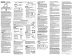
See the chart, TYPES
OF WELD
Figure 6, for detailed instructions
preparing the weld joint.
JOINTS,
GROUND
in
During the welding, the work pieces will
become hot and will tend to expand. The
expansion may cause the pieces to shift from
BUTT
CONNECTION
The ground clamp connection is part of the
current circuit. A poor connection at the
ground clamp will waste power and heat.
Scrape away dirt, rust, scale, oil or paint.
Make sure the ground clamp touches the
metal of the workpiece.
for
45 PLATE
CLAMP
WELD
JOINTS
" PLATE
37 5'
SINGLE
V JOINT
60"
DOUBLE
DOUBLE
BEVEL
I
CLOSED
--I1"TO
3/32"
JOINT
60.
_,/
YB"
1/16"
TO
VEEJOINT
118' *_
I[
"*-/
OPEN
_o.
JOINT
_'
SHOULDER
EDGE
_"
FILLET
WELD JOINT_
_
STRAP
JOINT
_//
FEATHER EDGE
1/8" OR MORE
DOUBLE VEE JOINT
SINGLE
V JOINT
JOfNT
SINGLE
DOUBLE
STRAP
F{LLET
T-JOINT
DOUBLE
FILLET
T-JOINT
JOINT
Figure 6. Types of Weld Joints
13
LEARNING
TO WELD
1.
MIG (Metal Inert Gas) welding is the process
of uniting metallic parts by heating and
allowing the metals to flow together through
the use of an electrical arc. The electrical arc
is created between a continuous consumable
wire electrode (the welding wire) and the
work piece. An inert shielding gas is used to
protect the weld puddle from contamination
and enhance the welding capabilities of the
electrical arc.
Whether you have welded before or not, it is
important that you become familiar with your
new welder, its controls, and the results
achieved at different settings. We strongly
recommend
that you practice with your new
welder on scrap metal trying different heat
settings, base metal thicknesses,
and welding positions for each type and size of wire
you will be using. By doing this you will gain
a feel for how changes in these welding
variables affect the weld.
Angle A (Figure 7) can be varied, but in
most cases the optimum angle will be 60
degrees. The point at which the gun
handle is parallel to the work piece. If
angle A is increased, penetration will
increase. If angle A is decreased,
penetration will decrease also.
L\\\\\\\\\\\\\\\\\\\\\\\q
Figure
.
7. Gun Position,
Angle A
Angle B (Figure 8) can be varied for two
reasons: to improve the ability to see the
arc in relation to the weld puddle and to
direct the force of the arc.
45 °
I
Of course, if you have not welded before,
you will need to develop welding skills and
techniques as well.
The self-taught
welder learns through a
process of trial and error. The best way to
teach yourself how to weld is with short
periods of practice at regular intervals. All
practice welds should be done on scrap
metal that can be discarded. Do not attempt
to make any repairs on valuable equipment
until you have satisfied yourself that your
practice welds are of good appearance
and
free of slag or gas inclusions. What you fail
to learn through practice will be learned
through mistakes and re-welds later on.
HOLDING
THE
GUN
The best way to hold the welding gun is the
way that feels most comfortable to you.
While practicing to use your new welder,
experiment
holding the gun in different
positions until you find the one that seems to
work best for you.
Position the Gun to the Work Piece
There are two angles of the gun nozzle in
relation to the work piece that must be considered when welding.
14
#,\\\\\\\\\\\'t
Figure
8. Gun Position,
Angle B
The force of the welding arc follows a
straight line out of the end of the nozzle.
If angle B is changed, so will the direction of
arc force and the point at which penetration
will be concentrated.
Qn a butt weld joint, the only reason to vary
angle B from perpendicular
(straight up) to
the work piece would be to improve visibility
of the weld puddle. In this case, angle B can
be varied anywhere from zero to 45 degrees
with 30 degrees working about the best.
On a fillet
positioned
the angle
members
fillet weld
weld joint, the nozzle is generally
in such a manner so as to split
between the horizontal and vertical
of the weld joint. In most cases, a
will be 45 degrees.
Distance
from the Work
Piece
The end of the welding gun is designed with
the contact tip recessed from the end of the
nozzle and the nozzle electrically insulated
fromthe restof the gun.This permitsthe
operatorto actuallyrestthe nozzleon the
work pieceand dragit alongwhilewelding.
This can be very helpfulto beginningwelders
to steadythe gun,allowingthe welderto concentrateon weldingtechnique.If the nozzleis
held off the workpiece,the distancebetween
the nozzleand the workpiece shouldbe kept
constantandshouldnot exceed1/4 inchor
the arc may beginsputtering,signalinga loss
in weldingperformance
LAYING
PUSH
Figure
9. Gun Travel
PULL
Direction
For most welding jobs you will pull the gun
along the weld joint to take advantage of the
greater weld puddle visibility.
A BEAD
,
AND SKIN! Prolonged exposure to the welding arc can cause blindness and burns.
Never strike an arc or begin welding until you
are adequately
protected. Wear flameproof
welding gloves, a heavy long sleeved shirt,
cuffless trousers, high topped shoes and a
welding helmet.
WARNING
ELECTRIC
SHOCK CAN KILL! To prevent
ELECTRIC SHOCK, do not perform any
welding while standing, kneeling, or lying
directly on the grounded work.
WELDING
TECHNIQUES
TRAVELING
THE GUN
Gun travel refers to the movement of the gun
along the weld joint and is broken into two elements: Direction and Speed. A solid weld bead
requires that the welding gun be moved
steadily and at the right speed along the weld
joint. Moving the gun too fast, too slow, or
erratically will prevent proper fusion or create a
lumpy, uneven bead.
1. TRAVEL
DIRECTION
is the direction
TRAVEL
SPEED
is the rate at which the
gun is being pushed or pulled along the
weld joint. For a fixed heat setting, the
faster the travel speed, the lower the
penetration and the lower and narrower
the finished weld bead. Likewise, the
EXPOSURE
TO A WELDING ARC IS
EXTREMELY
HARMFUL TO THE EYES
_
Puddle
slower the travel speed, the deeper the
penetration and the higher and wider the
finished weld bead.
TYPES
OF WELD
BEADS
The following paragraphs discuss
commonly
used welding beads.
the most
Once you have the gun in position with the
wire lined up on the weld joint, lower your
helmet, pull the trigger and the arc will start.
In a second or two you will notice a weld
puddle form and the base of the bead
beginning to build. It is now time to begin to
move with the gun. If you are just learning to
weld, simply move the gun in a straight line
and at a steady speed along the weld joint.
Try to achieve a weld with the desired
penetration and a bead that is fairly flat and
consistent in width.
You can begin to try some different
bead types.
weld
There are two basic types of weld beads, the
stringer bead and the weave bead.
the
gun is moved along the weld joint in relation to the weld puddle. The gun is either
PUSHED (see Figure 9) into the weld puddle or PULLED away from the weld puddle.
15
1. The STRINGER
BEAD (Figure 10) is
formed by traveling with the gun in a straight
line while keeping the wire and nozzle
centered over the weld joint. This is the
easiest type of bead to make.
Figure
10. Stringer
2. The HORIZONTAL
POSITION (Figure 13)
is next in difficulty level. It is performed very
much the same as the flat weld except that
angle B (see POSITION OF THE GUN TO
THE WORK PIECE - p14) is such that the
wire, and therefore the arc force, is directed
more toward the metal above the weld joint.
This is to help prevent the weld puddle from
running downward while still allowing slow
enough travel speed to achieve good penetration. A good starting point for angle B is
about 30 degrees DOWN from being
perpendicular
to the work piece.
Weld Bead
2. The WEAVE BEAD (Figure 11) is used
when you want to deposit metal over a wider
space than would be possible with a stringer
bead. It is made by weaving from side to
side while moving with the gun. It is best to
hesitate momentarily
at each side before
weaving back the other way.
Figure
Figure
WELDING
11. Weave
Weld Bead
POSITIONS
There are three basic welding
horizontal, and vertical.
positions:
flat,
1. The FLAT POSITION (Figure 12) is the
easiest of the welding positions and is probably the one you have been using thus far. It is
best if you can weld in the fiat position if at all
possible as good results are easier to achieve.
Figure 12. Flat Position Weld
16
13. Horizontal
Position
Weld
3. The VERTICAL
POSITION (Figure 14) is
the next most difficult position. Pulling the
gun from top to bottom may be easier for
many people, but in some instances it can
be difficult to prevent the puddle from running downward.
Pushing the gun from bottom to top may provide better puddle control
and allow slower rates of travel speed to
achieve deeper penetration. When vertical
welding, angle B (see POSITION OF THE
GUN TO THE WORK PIECE - p14) is
usually always kept at zero, but angle A will
generally range from 45 to 60 degrees to
provide better puddle control.
Figure
14. Vertical
Position
Weld
MULTIPLE
PASS WELDING
Butt Weld Joints. When butt welding thicker
materials, you will need to prepare the edges
of the material to be joined by grinding a
bevel on the edge of one or both pieces of
the metal being joined. When this is done, a
V is created between the two pieces of
metal, that will have to be welded closed. In
most cases more than one pass or bead will
need to be laid into the joint to close the V.
Laying more than one bead into the same
weld joint is known as a multiple-pass
weld.
The illustrations
in Figure 15 show the
sequence for laying multiple pass beads
a single V butt joint.
Lap Joint Welded
In Three
f
T Joint in
Three Passes
Figure
into
NOTE: WHEN USING SELF-SHIELDING
FLUX-CORE
WIRE it is very important to
thoroughly
chip and brush the slag off each
completed weld bead before making another
pass or the next pass will be of poor quality.
Root Pass
First or
Passes
SPECIAL
16. Triple Pass Lap and
T Weld Joint
WELDING
METHODS
SPOT WELDING
The purpose of a spot weld is to join pieces
of metal together with a spot of weld instead
of a continuous weld bead. There are three
methods of spot welding: Bum-Through,
Punch and Fill, and Lap (see Figure 17).
Each has advantages and disadvantages
depending on the specific application as well
as personal preference.
PUNCH
AND
FILL
_
LAP SPOT
BURN
Figure
THROUGH
17. Spot Weld Methods
Finished
Weld
Figure
15. Triple
Pass
V Butt Joint
Fillet Weld Joints.
Most fillet weld joints, on
metals of moderate to heavy thickness, will
require multiple pass welds to produce a
strong joint. The illustrations in Figure 16
show the sequence of laying multiple pass
beads into a T fillet joint and a lap fillet joint.
1. The BURN-THROUGH
METHOD welds
two overlapped pieces of metal together
by burning through the top piece and into
the bottom piece.
With the burn-through
method, larger wire
diameters tend to work better than smaller
diameters because they have greater
current carrying capabilities allowing the
arc to burn through very quickly while
leaving a minimal amount of filler metal
build up.
17
Do not use 0.030 inch self-shielding
flux-core
wires when using the burn-through
method
unless the metal is VERY thin or excessive
filler metal build-up and minimal penetration
is acceptable.
Always select the HIGH heat setting with the
burn-through
method and tune-in the wire
speed prior to making a spot weld.
GENERAL
1.
2. The PUNCH AND FILL METHOD produces a weld with the most finished
appearance
of the three spot weld methods. In this method, a hole is punched or
drilled into the top piece of metal and the
arc is directed through this hole to penetrate into the bottom piece. The puddle is
allowed to fill up the hole leaving a spot
weld that is smooth and flush with the sur-
2.
3.
face of the top piece.
4.
Select the wire diameter, heat setting, and
tune-in the wire speed as if you were
welding the same thickness material with
a continuous bead.
3. The LAP SPOT METHOD directs the
welding arc to penetrate the bottom and
top pieces, at the same time, right along
each side of the lap joint seam.
Select the wire diameter, heat setting, and
tune-in the wire speed as if you were
welding the same thickness material with
a continuous bead.
SPOT
WELDING
INSTRUCTIONS
1. Select the wire diameter and heat setting
recommended
above for the method of
spot welding you intend to use.
2. Tune in the wire speed as if you were
going to make a continuous weld.
3. Hold the nozzle piece completely perpendicular to and about 1/4 inch off the work
piece.
4. Pull the trigger on the gun and release it
when it appears that the desired penetration has been achieved.
5. Make practice spot welds on scrap metal,
varying the length of time you hold the
trigger, until a desired spot weld is made.
6. Make spot welds on the actual work piece
at desired locations.
18
MAINTENANCE
This welder has been engineered to give
many years of trouble-free
service providing
that a few very simple steps are taken to
properly maintain it.
Keep the wire drive compartment
lid
closed at all times unless the wire needs
to be changed or the drive tension needs
adjusting.
Keep all consumables (contact tips, nozzles, and gun liner) clean and replace when
necessary. See CONSUMABLE
MAINTENANCE and TROUBLESHOOTING
later in
this section for detailed information.
Replace power cord, ground cable,
ground clamp, or gun assembly when
damaged or worn.
Periodically
clean dust, dirt, grease, etc.
from your welder. Every six months or as
necessary, remove the side panels from
the welder and air-blow any dust and dirt
that may have accumulated
inside the
welder.
flWARNIN
ELECTRIC
G
SHOCK
CAN KILL! To reduce
the risk of electric shock, always unplug the
welder from its ac power source before
removing side panels.
CONSUMABLE
MAINTENANCE
IT IS VERY IMPORTANT TO MAINTAIN THE
CONSUMABLES
TO AVOID THE NEED
FOR PREMATURE
REPLACEMENT
OF
THE GUN ASSEMBLY.
MAINTAINING
THE CONTACT
TIP
The purpose of the CONTACT TIP is to
transfer welding current to the welding wire
while allowing the wire to pass through it
smoothly.
Always use a contact tip stamped with the
same diameter as the wire it will be used with.
Note: Due to inherent variances in flux-cored
welding wire, it may be necessary to use a
contact tip one size larger than your flux core
wire if wire jams occur.
,
.
If the wire burns back into the tip, remove
the tip from the gun and clean the hole
running through it with an oxygen-acetylene torch tip cleaner or tip drill.
Over time, the hole in the contact tip will
become worn by the wire passing through
it. The more worn this hole becomes, the
less efficient is the transfer of welding
current to the wire and eventually arc
breakage and difficult arc starting will
result. Replace contact tips when signs of
wear become apparent.
CAUTION
KEEP THE NOZZLE
CLEAN!
During the welding process, spatter and slag
will build up inside the nozzle and must be
cleaned out periodically. Failure to clean
and/or replace the nozzle in a timely fashion
WILL CAUSE DAMAGE TO THE FRONTEND OF THE GUN ASSEMBLY, which is
NOT REPLACEABLE.
The results of the
inaction will REQUIRE THE REPLACEMENT
OF THE ENTIRE GUN ASSEMBLY.
1.
2.
Stop welding and clean any accumulated
slag or spatter from the nozzle every 5 to
10 minutes of welding time.
If slag cannot be thoroughly
cleaned from
the nozzle, REPLACE THE
NOZZLE!
Failure to keep the nozzle adequately
cleaned can result in the following problems:
A SHORTED
nozzle results when spatter
buildup bridges the insulation in the nozzle
allowing welding current to flow through it as
well as the contact tip. When shorted, a
nozzle will steal welding current from the
wire whenever it contacts the grounded work
piece. This causes erratic welds and reduced
penetration.
In addition, a shorted nozzle
overheats the end of the gun which can
DAMAGE the front-end of the gun.
TESTING
FOR A SHORTED
NOZZLE
Arcing between the nozzle and the work
piece ALWAYS means the nozzle is shorted,
but this can be hard to detect through the
lens of a welding helmet. The following
testing method is another way to tell if a
nozzle is shorted.
With the welder unplugged from the ac
power source, touch the probes of an ohmmeter or continuity tester to the end of the
contact top and the outside of the nozzle. If
there is any continuity at all, the nozzle IS
shorted. Clean or replace as needed.
REPLACE
A GUN LINER
When installing a new gun liner, care must
be taken not to kink or otherwise damage the
gun liner. See Figure 18 for the drive assembly and Figure 19 for the gun assembly.
1. Turn OFF welder POWER SWITCH and
2.
3.
4.
5.
6.
7.
8.
9.
unplug welder from power supply.
Open the welder side panel.
Loosen the tension arm and lift it up off
the drive roller.
Turn the wire spool counter-clockwise
sure to hold onto the wire itself while
(be
turn-
ing the spool or the wire will unspool itself
when it becomes free of the gun liner), and
remove wire from gun assembly.
Lay gun cable and gun handle straight
out in front of unit.
Remove gun liner holding clamp by
removing two self tapping screws and
two bolts with nuts.
Take gun handle halves apart by
removing five phillips head screws.
Remove liner from fast coupler fitting on
brass block. Depress lip on fast coupler
back towards fitting and pull liner out.
Remove liner from outer torch sleeve and
pull out.
10. Remove fast coupler
block.
fitting from
brass
11. Install new liner, starting from handle end
and feeding towards unit with fitting end
of liner going towards the brass block.
12. Fit liner for length at feeder end by cutting liner with wire cutters.
13. Reinstall liner holding clamp at feeder.
14. Return all components
to the handle
casing and realign them as they were
originally.
15. With both halves of the handle case in
place, tighten the five phillips head
screws.
16. Reinstall the welding wire according to
specifications
in INSTALL THE WELDING
WIRE section.
17. Close side panel.
18. Plug welder into power supply and turn
POWER SWITCH to ON position.
19
Drive
Tension
Drive
Tension
Adjustment
Arm
Gun
Assembly
(Tail -nd)
The following paragraphs describe the
procedures required to maintain and
troubleshoot
your welder.
MAINTAINING
THE
WELDER
Except for internal and external cleaning,
cleaning the nozzle, and occasionally
retightening
screws, there is no periodic
maintenance
recommended
for your welder.
TROUBLESHOOTING
The TROUBLESHOOTING
Inlet
Guide
Tube
Figure
Drive
Gun
Strain
Relief
Roller
Liner
Clamp
18. Drive Assembly
Nozzle
Contact Tip
Gas Diffuser
3onductor Tube
Tube
Insulation
3rass
Block
Trigger
Live Wire
Switch
Contact
Gun
Liner
Handle
Casing
Switch
Contact.
Wire
Gun
Cable
Figure
20
19. Gun Assembly
information
on
the next page is provided as a guide to help
resolve some of the more common problems
that could be encountered,
Table 4 is a troubleshooting
table provided to
help you determine a possible remedy when
you are having a problem with your welder.
This table does not provide all possible
solutions, only those possibilities considered
to likely be common faults. The table
consists of a TROUBLE or symptom, a
POSSIBLE CAUSE for that symptom, and a
POSSIBLE REMEDY for that symptom.
TROUBLE
POSSIBLE
CAUSE
POSSIBLE
REMEDY
Dirty, porous, brittle weld
Plugged welding nozzle
Clean or replace nozzle
Wire feed works but no arc
1. Bad ground or loose
connection
1 Check ground and
connections. Tighten as
necessary.
2. Check connection to gun
or replace gun
2. Bad connection
faulty gun
Arc works but not
feeding wire
Nothing works
Low output or non)enetrating weld
to gun or
1. Faulty wire speed circuit
board
2. No tension on the drive
roller
3. Faulty drive motor (very
rare)
1. Replace wire speed circuit
board
2. Adjust the drive tension
1. Faulty trigger on gun
2. Exceeded duty cycle;
thermal protector opened
1. Replace trigger
2. Allow welder to cool at
least 10 minutes (observe
and maintain proper duty
cycle)
3. Replace transformer
3. Faulty transformer
(rare)
1. Loose connection
machine
inside
2. Too long or improper
extension cord
3. Wrong type or size wire
4. Poor ground connection
5. Wrong size contact tip
6. Loose gun connection
faulty gun assembly
Wire is jamming or
"birdnesting" at the
drive roller
Wire burns back to
i contact tip
or
1. Too much tension on drive
miler
2. Gun liner worn or damaged
3. Contact tip is clogged or
damaged
4, Liner is stretched or is too
long
1. Gun liner is worn or
damaged
2. Liner stretched or is too
long
3. Wrong size contact tip
4. Contact tip clogged or
damaged
3. Replace the drive motor
1. Blow inside of machine out
with compressed air, clean
and tighten all connections
2. See EXTENSION CORDS
in this manual
3. Use only 0.030 (0.8mm)
E71T-GS self shielding
flux-core wire
4. Reposition clamp and check
cable to clamp connection
5. Use only 0.030 inch
(0.8mm) contact tip
6. Tighten gun or replace gun
1. Adjust the drive tension
(see INSTALL THE
WELDING WIRE)
2. Replace gun liner
3. Replace contact tip
4. Tdm liner to proper length
1. Replace gun liner
2. Trim liner to proper length
3. Use correct size contact tip
4. Replace contact tip
Ground clamp and/or ground
cable gets hot
Bad connection from cable
to clamp
-Rghtenconnectionor replace
cable
Gun nozzle arcs to work
surface
Slag buildup inside nozzle or
nozzle is shorted
Clean or replace nozzle as
needed
21
22
No.
Code
Description
01
02
03
04
05
06
07
08
09
09a
10
11
12
13
14
15
16
17
18
19
20
21
22
23
24
25
26
27
28
29
30
31
32
33
34
35
36
37
38
39
40
41
42
WE20568-21600036
WE20568-05000062
WE20568-05000061
WE20568-33720108
WE20568-05000063
WE20568-05000064
WE20568-44120100
WE20568-44135097
WE20568-04600108
WE20568-21690270
WE20568-22400083
WE20568-04600113
WE20568-22200036
WE20568-22200035
WE20568-44400018
WE20568-23000080
WE20568-22710001
WE20568-20220018
WE20568-21605010
WE20568-43210147
WE20568-22110005
WE20568-21690001
WE20568-21690310
WE20568-04600144
WE20568-33805074
WE20568-21690278
WE20568-21020017
WE20568-21020018
WE20568-21030010
WE20568-21020008
WE20568-21020026
WE20568-21035002
WE20568-21025011
WE20568-21020057
WE20568-21020056
WE20568-21020059
WE20568-21000005
WE20568-21025029
WE20568-21020047
WE20568-77600314
WE20568-21905002
WE20568-21905007
WE20568-21905011
Welder Handle
Right Upper Panel
FronVLower Panel
Dividing Panel
Left Side Panel
Removable Access Panel
Transformer
60Hz 115V 50x70AL
Choke _3.9 40x25AL
Kit Spool Holder for _16 Spools-Comp.
Locking Pin for Spool Holder
Rectifier PMS 30B F/1 Type
Complete Thermostat
100 ° +Support
Red Voltage Switch
Yellow Power Switch 16A-250V
Plastic Wire Feeder _28 06-08 ROL
Gun 8mm 2
EC. Board E0585.1 220V
Power Cord 3x4WG14 MT. 2.5
Cable Clamp For Hole 020
Ground Cable 10MM 2
Ground Clamp 120A
Gun Grommet on Front Panel
Red Wire Feed Speed Knob
Wire Feeding Motor _28 +Pinion
Wire Feed Roller _7x25.023-.030
Gun Pressure Cover
Self-Tapping
Screw for Cabinet
Self-Tapping Screw for Transformer &Choke
Washer for Transformer
& Choke
Self-Tapping
Screw for Thermostat
Self-Tapping Screw for Spool Holder
Gear Washer for Spool Holder
Hex Nut for Rectifier
Self-Tapping
Screw for Wire Feeder
Self-Tapping
Screw for Wire Feeder
Self-Tapping
Screw for Wire Feeder
TE Screw
Hex Nut
Self-Tapping
Screw for Handle
Suggested
Settings Label
Plastic Welding Mask
Dark Glass for Welding Mask
Hammer Brush
Qty.
1
1
1
1
1
1
1
1
1
1
1
1
1
1
1
1
1
1
2
1
1
1
1
1
1
1
16
8
8
2
1
5
1
2
2
1
1
2
2
1
1
1
1
GASLESS
WIRE FEED WELDER
MODEL 196.205680
PARTS DIAGRAM
22
13
12
1
26
24
33
23 9a
26
,17
10
11
29
12
13
2'7
23
No. Code:
Description
Qty.
01
02
03
04
05
06
07
08
09
10
11
12
13
14
15
16
Black Gun Handle
1
Red Trigger for Gun
Brass Block
Gun Neck
Thread Guide Wire Liner
Conductor Tube Insulation
Gas Diffuser
1
1
1
1
1
1
0.8mm Contact Tip
Nozzle
1
1
Pin for Gun Trigger
No-Gas Gun Contact Spring
Self Tapping Screw TCC 3,9X16
Stainless Wire Liner 1,4X4 Blue L=2500
Rubber Outer Sleeve _ 17,5 + Hoses L--2200
Gun Neck with Outside Liner and Diffuser
Gas Valve No-Gas w/Neck
1
1
5
1
1
1
1
WE20568-21690300
WE20568-21690301
WE20568-23005011
WE20568-23005145
WE20568-23005091
WE20568-23005090
WE20568-23005146
WE20568-23005019
WE20568-23005147
WE20568-33810090
WE20568-33800009
WE20568-21020012
WE20568-23005131
WE20568-30900022
WE20568-23005148
WE20568-23005179
3
1
12
13
16
24
GASLESS
WIRE
FEED WELDER
MODEL
196205680
WIRING
DIAGRAM
......
W
m
o
ol
Co
c.n
_,
MOTOR-
...............
I _
i
MOTOR+
-
IN --
'+IN
I
+
25
Po
o_
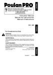
SUGGESTED
JCRRFTSMAN°I
Proper wire
direction
from spool
_-_ To Drive
WELDING
Motor
SETTINGS
WIRE
.O3O in (0.8 mm)
Flux-Core Wire
MIN/2
MINI4
MIN/5
I 'L0] II L'TH =1_'1_111d
After installing new wire spool, make sure
welding wire is inserted into torch hose liner
and wire tension knob is correctly adjusted
before pulling welding torch trigger,
FOR WELDER
These are recommendations
only - variations in input power, welding positions, and
wire will affect the weld characteristics.
Use the voltage setting and wire speed
indicated as a starting point - then adjust for variables such as stick out, travel
speed, weld angle, cleanliness of metal, etc.
MAX/2
MAX/4
MAX/6
:[eA','Jl:it-1_:_ _
Read all instructions
and warnings SUpplied with this welder before attempting
to use or service it. Also read all warnings and cautions on the welder.
If you need assistance,
call Customer Service at 1-800-227-9603.
Garantia limitada de Craftsman ............ 27
indice ........................................................
27
Resumen de Seguridad .......................... 28
Informacion
Importante de
Seguridad
............................................
28
Riesgos de Choque Electrico .............. 29
Riesgos de Destello del Arce .............. 29
Riesgos de Incendio ............................ 30
Riesgos de Vapores ............................ 31
Informaci6n Adicional de Seguridad ..32
Conozca su Soldadora
.......................... 33
Ensamblaje ..............................................
34
Desembalaje de la Soldadora .............. 34
Lista de Empaque .................................. 34
Instalacion del Asa ................................ 34
Ensamblaje de la Careta para Soldar ..34
Conexion al Suministro Electrice .......... 34
Cordenes de Extension ........................ 35
Selecci6n del Alambre Soldador .......... 35
Instalaci6n del Alambre soldador .......... 35
Operacion ................................................
36
Descripcion ............................................
36
Ciclo de Funcionamiento ...................... 36
Pretecci6n Termica Interna .................. 37
Controles e Indicadores ........................ 37
Preparaciones para Soldar .................... 37
Preparacion de la Pieza de Trabajo ...... 37
Preparaci6n de la Junta ........................ 37
Conexi6n de la Pinza a Tierra .............. 38
Aprendiendo a Soldar ............................ 39
Come Sujetar la Pistola ........................ 39
Posici6n de la Pistola con la
Pieza de Trabajo ................................ 39
Distancia de la Pieza de Trabajo ........ 39
Come Formar el Cord6n de Soldadura 40
Tecnicas para Soldar .......................... 40
Desplazamiento de la Pistola .............. 40
Tipos de Cordones de Seldadura ...... 40
Posiciones para Soldar ...................... 41
Soldadura de Pasadas MUltiples ........ 42
Metodos Especiales para Soldar .......... 42
Soldadura de Puntos ............................ 42
Instrucciones para la
Soldadura de Puntes .......................... 43
Mantenimiento ........................................
43
Mantenimiento General ........................ 43
Mantenimiento de Insumos ................ 43
Mantenimiento de la
Punta de Contacto .............................. 43
Prueba de Cortocircuito en la
Boquilla ..............................................
44
Cambio del Forro de la Pistola ............ 44
Mantenimiento de la Soldadura ............ 45
Diagn6stico de Problemas .................... 46
Lista de Piezas ........................................ 47
Diagrama de Cableado .......................... 50
Graduaciones
Sugeridas
...................... 51
Garantia limitada de Tres Aries de la Soldadora
Craftsman
Si cualquier parte de esta soldadora, excepto
per la pistola o los cables, fallase debido a un
defecto de materiales o de fabricacion durante
tres afios a partir de la fecha de compra,
devolverla al Centro de Reparaciones y
Repuestos de Sears mas cercano y Sears la
reparara sin costo alguno. Sears reparara la
pistola o los cables sin costo alguno solo
durante el periodo de un afio a partir de la
fecha de compra. Esta garantia no cubre las
piezas que se gastan como las puntas de
contacto o boquillas, que se consumen durante
la operaci6n normal de la soldadura.
Esta
garantia se aplica solo cuando la unidad se
usa en los Estados Unidos. Esta garant[a
otorga derechos especificos y usted tambien
podria tener otros derechos que varian de un
Estado a otro.
Sears, Roebuck and Co., D/817WA,
Estates, IL 60179
Hoffman
27
Todo artesano respeta las herramientas con las
que trabaja. Sabe que las herramientas
representan
constantes.
a6os de mejoras y desarrollo
Un verdadero artesano tambien
sabe que las herramientas
usan mal o se maltratan.
son peligrosas
si se
Nota:
Los siguientes sfmbolos de alerta de
seguridad identifican mensajes de
seguridad importantes en este manual.
Cuando vea uno de estos simbolos que
se indican a continuaci6n, est6 alerta a la
posibilidad de lesiones personales y lea
cuidadosamente el mensaje que le sigue.
s e--o
rede
so
La lectura de este Manual del Operador antes de
usar la soldadora, permitir_l hacer un trabajo
mejor y mas seguro. Aprenda los usos y
Iimitaciones de la soldadora, asf como los
peligros relacionados con el trabajo de
soldadura.
descargas electricas
pasos que siguen.
Este simbolo indica riesgos de
incendio durante los pasos que
siguen.
INFORMACION
IMPORTANTE
DE SEGURIDAD
A continuacion se proveen pautas de seguridad
para ayudarle a operar su soldadora nueva
bajo las condiciones m_ls seguras posibles.
Cualquier equipo que use energia electrica
puede ser potencialmente peligroso cuando no
se siguen o se desconocen las instrucciones
de seguridad y de manipulaci6n.
A continuacion se provee la informaci6n
necesaria para que el usuario opere y use la
unidad en forma segura.
Un aviso de ADVERTENCIA
precediendo un
paso de un procedimiento indica que el
siguiente paso podria lesionar a la persona si
es que no se cumplen con las precauciones de
seguridad apropiadas.
Un aviso de PRECAUCION precediendo un
paso de un procedimiento indica que el
siguiente paso podria dal_ar el equipo en uso.
Se puede usar una NOTA antes o despues de
un paso en un procedimiento para remarcar o
explicar algo propio de ese paso.
LEER TODAS LAS INSTRUCCIONES
DE
SEGURIDAD CUIDADOSAMENTE
antes de
intentar instalar, operar o darle servicio a esta
soldadora,
Ignorar estas instrucciones, podria
causar lesiones personales y/o da5os a la
propiedad.
CONSERVAR ESTAS INSTRUCCIONES
PAPA REFERENCIA FUTURA,
28
durante los
Este simbolo indica que se debe
usar una careta para soldar durante
los pasos que siguen para proteger
los ojos contra riesgos de lesiones y
quemaduras por destellos,
Este simbolo indica que existe la
posibilidad de riesgos de gases
t6xicos durante la ejecuci6n de los
siguientes pasos.
IT
Este simbolo indica que existe la
posibilidad de quemaduras por
escoria caliente durante la ejecuci6n
de los siguientes pasos.
Este simbolo indica que deben
usarse protectores de ojos para
proteger contra partfculas
disparadas al aire en la ejecuci6n de
los siguientes pasos.
• Existen publicaciones sobre normas de
seguridad. Estas se indican en la
informaci6n adicional de seguridad al
final de este resumen de seguridad.
El C6digo Electrico Nacional (EE.UU.), las
normas de la Ley de Salud y Seguridad
Ocupacional (OSHA), los c6digos industriales
locales y los requisitos locales de inspecci6n
tambien sirven de base para la instalaci6n, uso
y servicio del equipo.
RIESGOS
_
DE CHEQUE
ELECTRICO
ADVERTENCIA
iLAS DESCARGAS ELECTRICAS PUEDEN
MATAR! Para reducir el riesgo de muerte o
lesiones serias per cheques electricos, se debe
leer, entender y acatar las siguientes
instrucciones de seguridad. Adicionalmente,
cerciorarse que todas las personas que operen
el equipo de soldar y que esten en el area de la
soldadura, tambien entiendan y acaten estas
medidas de seguridad.
• ilMPORTANTE!
PARA REDUCIR EL
RIESGO DE MUERTE, LESIONES O
DANES A LA PROPIEDAD, NO INTENTAR
OPERAR este equipo de soldar hasta
haber leido y entendido el siguiente
resumen de seguridad.
• Bajo ningt_n motive hacer contacto fisico con
parte alguna de la soldadora durante el
circuito de corriente para soldar, que incluye:
a. La pieza de trabajo o cualquier material
conductor en contacto con esta,
b. La pinza de conexion a tierra,
c. El electrode o alambre de soldar,
d. Cualquier otra pieza metalica en el
sujetador del electrode o pistola
alimentadora de alambre.
• No soldar en un area ht]meda ni entrar en
contacto con una superficie hQmeda o
mojada.
• No intentar soldar si es que alguna parte de la
ropa o del cuerpo estuviese mojada.
• No permitir que el equipo de soldar entre en
contacto con agua o humedad.
• No arrastrar los cables soldadores, la pistola
alimentadora de alambre, ni el cord6n de
suministro electdco de la soldadora. Tampoco
permitir que estos entren en contacto con
agua o humedad.
• No tocar la soldadora, intentar encenderla o
apagarla si alguna parte del cuerpo o de la
ropa est& ht]meda o si usted esta en contacto
fisico con agua o humedad.
• No intentar enchufar la soldadora a un
suministro electrico si alguna parte del cuerpo
o de su ropa est_ hOmeda o si usted esta en
contacto con agua o humedad.
• No conectar el sujetador ni soldar la pieza de
trabajo a un tube conductor de electricidad.
• No alterar el cordon de suministro el6ctrico, ni
el enchufe en forma alguna.
• No intentar enchufar la soldadora a un
tomacorriente si la clavija para conexion a
tierra en el enchufe del cordon estuviese
doblado, rote o faltante.
• No permitir que la soldadora se conecte a un
tomacorriente, ni intentar soldar si la
soldadora, los cables para soldar, el lugar
donde se va a soldar o el cordon de
suministro electrico estan expuestos en forma
alguna a precipitacion atmosferica,
salpicaduras o chorros de agua salada.
• No cargar los cables de soldadura enrollados
alrededor del hombre ni parte alguna del
cuerpo cuando esten enchufados a la
soldadora.
• No modificar el cableado, las conexiones a
tierra, interruptores ni fusibles del equipo de
soldar.
• Usar guantes de soldar para ayudar a aislar
las manes del circuito de soldadura.
• Mantener todos los envases con liquidos
alejados Io suficiente de la soldadora y de la
zona de trabajo, de mode que si el liquido se
derrama no tenga posibilidades de entrar en
contacto con parte alguna de la soldadora o
del circuito electrico de soldar.
• Reemplazar INMEDIATAMENTE cualquier
pieza rajada o dafiada que estuviese aislada o
sirvan de aislamiento, come los cables de
soldar, el cord6n de suministro electrico o el
sujetador de electrodes.
DESTELLOS
p
PELIGROSOS
ADVERTENCIA
iLOS RAYOS DE LOS ARCOS PUEDEN
LESIONAR LOS OJOS Y QUEMAR LA PIEL!
Para evitar estos riesgos, se debe leer,
entender y acatar las siguientes instrucciones
de seguridad. Adicionalmente,
cerciorarse que
todas las personas que operen el equipo de
soldar y que esten en el _rea de la soldadura,
tambien entiendan y acaten estas medidas de
seguridad.
La careta y la lente filtrante deben
cumplir con la Norma Z87.1 de ANSI.
• No mirar a un arco el6ctrico sin la
proteccion adecuada.
• No mirar a un arco el6ctrico sin la protecciSn
adecuada.
• Un arco el_ctrico es extrernadamente
bdllante y con protecci6n ocular adecuada o
sin ella, la retina puede quemarse dejando
29
•
•
•
•
•
•
una mancha negra permanente en el campo
de vision. Debe usarse una careta con un
lente oscuro No. 10 (minimo).
No encender el arco de soldar hasta que
todos los observadores y usted (el soldador)
tengan puesta su careta de soldar.
No usar cascos ni caretas rajadas o rotas, y
reemplazar inmediatamente los lentes
filtrantes.
No permita que la parte no aislada de la
pistola alimentadora de alambre haga
contacto con la pinza de conexion a tierra o
la pieza de trabajo conectada a tierra para
evitar que se forme un arco al hacer
contacto.
Proveer caretas con lente filtrante No. 10 a
los observadores.
Usar ropa protectora. La luz intensa del arco
de soldadura puede quemar la piel de la
misma forma que el sol, aun a traves de ropa
liviana. Use ropa oscura de material pesade.
La camisa que se use debe ser de manga
larga y el cuelle debe mantenerse abotonade
para proteger el peche y el cuelle.
Preteccion contra los reflejos de los rayos del
arco. Los rayos del arco pueden reflejarse
en superficies brillantes come las superficies
con pintura brillante, de aluminio, acero
inoxidable y vidrio. Es posible que sus ojos
se lesionen per los reflejos de los rayos del
arco, aQn cuando se use careta protectora.
Si suelda con una superficie reflexiva atr_s
suyo, los rayos del arco pueden rebotar de la
superficie, luego de los lentes filtrantes al
costado de su careta y de ahi a sus ojos. Si
existe un rondo reflexive en la zona del
trabajo de soldadura, saquelo o cQbralo con
algo no inflamable y no reflexive. Los rayos
que reflejan de los arcos tambien pueden
causar quemaduras de la piel, ademas de
lesiones a los ojos.
RIEGOS
DE INCENDIO
ADVERTENCIA
iLOS INCENDIOS O EXPLOSIONES PUEDEN
CAUSAR MUERTE, LESIONES Y DANOS A
LA PROPIEDAD!
Para evitar estos riesgos, se
debe leer, entender y acatar las siguientes
instrucciones de seguridad. Adicionalmente,
cerciorarse que todas las personas que operen
el equipo de soldar y que esten en el area de
la soldadura, tambien entiendan y acaten estas
30
medidas de seguridad,
iRECUERDE!
Per su
naturaleza, los arcos de soldar producen
chispas, gotean metal derretido y escoria
caliente y pedazos de metal caliente que
pueden iniciar incendios, quemar la piel y
lesionar los ojos.
• No usar guantes ni ropa que contenga aceite,
grasa u otras sustancias inflamables.
• No usar preparaciones inflamables en el
cabello.
• No soldar en un area hasta haber verificado
que no existan materiales combustibles y/o
inflamables.
TENER EN CUENTA que las
chispas y la escoria puede velar 11 m (35') y
pasar per pequeSas rajaduras o aberturas.
Si su trabajo y los materiales combustibles
no pueden mantenerse separados un minimo
de 11 m (35'), protegerlos adecuadamente
para que no se enciendan, colocandoles
cubiertas protectoras resistentes al fuego.
• No soldar en paredes hasta haber revisado
que no existan materiales combustibles
haciendo contacto al otro lade de las
paredes, y si las hubiese, sacarlas.
• No soldar, cortar, ni realizar trabajos similares
en tambores, cilindros, tanques, ni otros
contenedores que hayan contenido
substancias inflamables o t6xicas. Las
tecnicas para evacuar las sustancias y
vapores inflamables para que un contenedor
quede seguro para soldar o cortar, son
bastante complejas y requieren
entrenamiento y capacitacion especial
• No format un arco electrico en un cilindro de
gas o de aire comprimido, ni en contenedor
presurizado alguno; porque se creara un &tea
quebradiza que podria causar una ruptura
violenta inmediatamente
o en el future come
consecuencia de una manipulaci6n ruda.
• No soldar ni cortar en una zona donde el aire
pueda contener polvo inflamable (come polvo
de granos), gases, liquidos o vapores (come
de gasolina).
• No agarrar metales calientes come la pieza
de trabajo o los restos de electrodes con las
manes desnudas.
• Usar guantes de cuero, camisa gruesa de
manga larga, pantalones sin dobladillo o
basta, botines que cubran los pies hasta
arriba, casco, careta y capa.
• Segun fuese necesario, usar ropa protectora
adicional come saco con mangas de cuero,
polainas o mandil resistentes al fuego. Las
chispas o metales calientes pueden alojarse
en dobladillo de las mangas, la basta de los
•
•
•
•
•
pantaloneso los bolsillos.Lospu6osy los
cuellosde las camisasdebenmantenerse
abotonadasy se debeeliminarlos bolsillos
delpechode la camisa.
iTenerequiposextintoresde incendioa
manoparauso inmediato!Se recomienda
un extintorportatilde quimicotipoABC.
Cuandose sueldeen posicionesporencima
de la cabeza,usartaponesdeoidos para
evitarquelas chispaso la escoriacaliente
caigandentrode losoidos.
Asegurarsequeel areadondese suelda
tengaun pisobueno,s61idoy seguro,
preferiblemente
de concretoo mamposteria,
sin Iosetas,alfombrasni otrosmateriales
inflamables.
Protegerlas paredes,cieloraso,y lospisos
de materialesinflamablesconcobertores
resistentesal calor.
Antesde abandonarel Areadondese ha
soldado,revisarqueno quedenchispas,
metaleso escoriacaliente,ni llamas.
RIESGOS
DE VAPORES
ADVERTENCIA
iLAS EMANACIONES,
GASES Y VAPORES
PUEDEN CAUSAR INCOMODIDAD,
ENFERMEDAD
O MUERTE!
Para evitar estos
riesgos, se debe leer, entender y acatar las
siguientes instrucciones de seguridad.
Adicionalmente,
cerciorarse
que todas las
personas que operen el equipo de soldar y que
esten en el Area de la soldadura, tambien
menos que primero se saque el
recubrimiento.
Asegurarse que el area este
bien ventilada y que el operador y todas las
otras personas en el area de la soldadura
usen equipos respiradores autocontenidos.
• No soldar, cortar ni calentar plomo, zinc,
cadmio, mercurio, berilio, ni metales similares
sin asesoramiento
profesional y sin haber
inspeccionado la ventilaci6n del area donde
se va a soldar. Estos metales producen
vapores EXTREMADAMENTE
TOXICOS que
pueden causar incomodidad, enfermedad o
muerte.
• No soldar ni cortar en areas donde existan
solventes clorinados.
Los vapores de los
hidrocarbones clorinados tales como el
tricloroetileno y percloroetileno, pueden
descomponerse
con el calor de un arco
el_ctrico o su radiaci6n ultravioleta.
Esto
puede generar fosgeno, un gas altamente
toxico y otros gases irritantes de los ojos y
los pulmones. No soldar ni cortar cuando
estos vapores puedan ingresar al area de
trabajo o donde la radiaci6n ultravioleta
pueda penetrar alas areas que contienen
aunque sea peque_as cantidades de esos
vapores.
• No soldar en un area confinada a menos que
este bien ventilada o el operador y todas las
otras personas en el area de la soldadura
usen equipos respiradores autocontenidos.
• Si se desarrolla una irritaci6n momentanea
de los ojos, nariz o garganta, deje de soldar
porque esto significa que la ventilaci6n no es
adecuada.
Paralice el trabajo y tome las
medias necesarias para mejorar la
ventilacion en el area de la soldadura.
No reinicie la soldadura si la incomodidad
fisica persiste.
entiendan y acaten estas medidas de
seguridad.
• No soldar en un
haber verificado
adecuada seg_n
Z49.1 de ANSI.
area si no hasta despu6s de
que tenga ventilacion
Io descrito en la Norma
Si la ventilaci6n no es
adecuada para intercambiar los vapores y
gases generados durante el proceso de
soldadura con aire fresco, no soldar a menos
que usted (el soldador) y todas las otras
personas en el area de la soldadura usen
equipos respiradores autocontenidos.
• No calentar metales cubiertos con o que
contengan materiales que produzcan
vapores toxicos (como acero galvanizado), a
31
INFORMACION ADICIONAL
DE SEGURIDAD
Para informaci6n
adicional
referente a la
seguridad para soldar, referirse a las siguientes
Normas y cumpla con Io que sea aplicable.
• Norma Z49.1 de ANSI-Seguridad
para Soldar
y Cortar: Se puede obtener en la Sociedad
Americana de Soldadura, 550 NW Le Jeune,
Miami, FL. 33126,
telefono (800) 443-9353,
fax (305) 443-7559;
www.amweld.org
o www.aws.org
• Norma Z87.1 de ANSI, Practicas Seguras
para el Trabajo y Educaci6n para la
Protecci6n de los Ojos y la Cara:
Se puede obtener en el
Instituto Nacional Americano de Normas,
11 West 42nd Street, New York,
New York 10036,
telefono (212) 642-4900,
fax (212) 398-0023,
www.ansi.org
• Norma 51B NSTA, Proceso de Corte y
Soldadura:
Se puede obtener en la
Asociaci6n Nacional
de Protecci6n Contra Incendios,
1 Batterymarch Park,
EO. Box 9101, Quince,
Ma. 02269-9101,
telefono (6t7) 770-3000,
fax (617) 770-0700,
www.nfpa.org
32
Norma 29CFR de OSHA, parte 1910,
Secci6n Q, Soldadura, Corte y Soldadura
Fuerte: Se puede obtener en la oficina de
OSHA en su estado, o en la Secretaria de
Trabajo de EE.UU.
Oficina de Relaciones Publicas,
Room N3847, 200 Constitucion Ave.,
Washington D.C. 20210,
www.osha.gov
Norma W117.2 de CSA, C6digo de
Seguridad para Soldar y Cortar:
Puede obtenerse de la Asociaci6n
Canadiense de Normas,
178 Rexdale Boulevard,
Etobicoke, Ontario, M9W 1R3,
www.csaca
• Norma A6.0 de la Asociaci6n Americana
Soldadura - Soldadura y Corte de
Contenedores que han Contenido
Combustible:
Se puede obtener de la Sociedad
Americana de Soldadura,
550 NW Le Jeune Road,
Miami, FL 33126,
telefeno (800) 443-9353,
fax (305) 443-7759,
www.amweld.org
o www.aws.org
de
Cordon de Suministro
Electrico:
Es un cord6n estandar de 120 voltios con
Vel de Alim del aqambre
As8
CabLe de la pistola
Interrupter
conexion a tierra. (Asegurarse de usar un
tomacorriente de 120 VCA, 60 Hz, monofasico
de 20 amperies).
Pinza para Conexion a Tierra: Su conexion a
la pieza de trabajo "completa" del circuito de
corriente para soldar de la soldadora; de Io
contrario no ser& posible soldar Una mala
conexi6n de la pinza de conexi6n a tierra hara
perder corriente y calor. Raspe la suciedad,
6xido, sarro, aceite o pintura antes de conectar
la pinza.
Cable de Conexibn
Pistola
soldadora
Pinza
Selector
de voltaje
Cable para paratierra
tierra
Figura 1. Soldadora Modelo 20568
Asa: Robust& montada encima para facilitar el
transporte de la soldadora.
Control
de Velocidad
del Alambre Soldador:
Usar este dial para regular la velocidad a la cual
la soldadora alimenta el alambre a la pistola.
1 es la velocidad mas lenta y 10 es la velocidad
mas r_pida. Se tendra que regular o "afinar" la
velocidad del alambre para las diferentes
condiciones de soldadura (espesor de los
metales, tipo de metal, tamafio de alambre,
eta). Cuando se Iogre afinar la velocidad, el
alambre de soldar se fusionara en el material
que se esta soldando tan pronto come pase per
la pistola soldadora.
Selector de Voltaje: Este selector de dos
posiciones regula el voltaje o "calor" de la
soldadora. Seleccionar MIN para el voltaje mas
bajo y MAX para el mas alto. Los materiales de
diferente espesor requieren diferentes
graduaciones de voltaje. Se necesita regular el
voltaje de acuerdo alas diferentes condiciones
de soldadura. Regulando adecuadamente el
voltaje y la velocidad de alimentaci6n del
alambre, se pueden hacer soldaduras limpias y
precisas. (Referirse a la Tabla de Regulaciones
Sugeridas en ta pagina 26 de este manual o en
el interior de la puerta de la soldadora).
Interrupter:
Enciende (ON) y apaga (OFF).
(Cerciorarse que el interrupter est_ en la
posici6n de apagado (OFF) antes de realizar
cualquier mantenimiento
a la soldadora).
a Tierra:
Conecta la
pinza a la parte interna de la soldadora.
Pistola Soldadora y Cable:
La pistola
soldadora controla el paso del alambre de
seldar al material que se suelda. El alambre
de seldar se afimenta a trav6s del cable
soldador y de la pistola soldadora cuando se
aprieta el gatillo de la pistola. Antes de
comenzar a soldar se necesita instalar una
punta de contacto y una boquilla de soldar en
el extreme de la pistola soldadora come se
describe mas adelante en este manual.
Terminos Propios de la Soldadura:
Ahora
que se ha familiarizado con las partes
principales de la soldadora, tome nora de los
siguientes terminos.
Los vera a Io largo de
este manual.
Charco de soldadura
fundida
(Weld puddle): Un volumen de metal de
soldadura fundido antes que se solidifique.
Angulo de Soldar: El angulo en que el
alambre de soldadura se extiende de la pistola
soldadora a la pieza que se esta soldando.
Escoria (Slag): La capa protectora que se
forma en la superficie de los metales fundidos.
Arco: Una descarga luminosa o rayo
sostenido de electricidad a traves de una
brecha en un circuito.
Cordbn de Soldadura:
La acumulaci6n
continuada extendida de soldadura que se
forma empujando o jalando el metal de aporte
fundido.
33
El siguiente procedimiento describe el proceso
para ensamblar, instalar, mantener y prepararse
para soldar con la nueva soldadora con
alimentador de alambre.
DESEMBALAJE
DE LA SOLDADORA
1. Extraer todas las cajas o bolsas que
contengan piezas o accesorios.
(La mayoria de las piezas se embarcan
dentro de la soldadora, abrir la puerta.)
2. Abrir las cajas o bolsas de embalaje e
inspeccionar si es que su contenido no haya
sufrido daflos.
3. Disponer las piezas sobre una superficie
y compararlas contra la lista de embalaje en
la Tabla 1 para familiarizarse con elias y
saber come se les denomina. Esto ayudara
cuando se lea el manual.
ENSAMBLAJE
DE LA
CARETA
PARA SOLDAR
1. Quitar la u_as retenedoras de la lente y
la tuerca del mango del braze de la
careta. (iNO DESECHARLOS!)
2. Colocar la lente oscuro en el espacio
provisto en la careta
3. Insertar los tornillos sujetadores de la
lente en los orificios a ambos lades de la
lente hasta que ajusten contra la lente.
4. Insertar la punta roscada del mango en el
orificio de la careta. Presionar firmemente hasta
que las roscas de la punta y la punta mas
pequeBa de abajo se enganchen en posici6n.
5. Desde el lade de dentro de la careta,
enroscar la tuerca del mango firmemente
en la punta.
Para el ensamblaje
de la careta, Ver la Figura 3
LISTA DE CONTENIDO
La Tabla 1 Contiene una lista de las piezas que
se encontraran en la caja.
Pieza
Tabla 1 - Lista de Embalaje
Cantidad
Soldadora
1
Careta para Soldar
1
Mango de la Careta para Soldar
1
Tornillos del Asa
2
Lente Oscuro
1
Asa de la Soldadora
1
Cepillo de Alambre/Martillo
1
Bolsa con Piezas
1
Punta de Contacto 0,030
5
Punta de Contacto 0,040
5
Boquilla
2
Alambre Flux-Core 0,030
227g (1/2 Lb)
Manual de Instrucciones
1
INSTALACION
DEL ASA
1. Insertar las pestaSas del asa en las ranuras
que est_n encima de la soldadora.
2. Insertar un tomillo grande de ranura recta
(incluido en la bolsa de accesorios) en
cada orificie del asa de la soldadora.
3. Ajustar firrnemente ambos tomillos con un
desarmador de punta plan& (Ver Figura 2)
I
1
|
|
Figura 2. Instalacibn
34
del Asa
Figura 3. Ensamblaje de la Careta
CONEXION
AL TOMACORRIENTE
_],ADVERTENCIA
iPeligro de Alto Voltaje en el Tomacorriente!
Consultar a un electricista calificado para la
instalaci6n adecuada de un tomacorriente.
• Para proteger al operador contra cheques
electricos, esta soldadora debe estar
conectada a tierra mientras este en use. Si
no se tiene la certeza de que el
tomacorriente este debidamente conectado a
tierra, hacerlo inspeccionar per un electricista
calificado.
No cortar la clavija de conexi6n a
tierra del enchufe ni alterarlo en forma
alguna. Tampoco usar adaptadores entre el
enchufe de la soldadora y el tomacorriente.
Cerciorarse que el INTERRUPTER este en
OFF (apagado) antes de enchufar la
soldadora a un tomacorriente monof_sico de
120 VCA, 60 Hz, 15 amperios. No operar la
soldadora si el voltaje del suministro es menor a
105 VCA o mayor a 132 VCA. Contactar a un
electricista calificado si es que este problema
existe. La soldadora funcionara adecuadamente
y/o se daflara si es que se opera con un
suministro electrico inadecuado o excesivo.
CORDONES DE
EXTENSION
Para el rendimiento 6ptimo de la soldadora, no se
deben usar cordones de extensi6n a menos que
sea absolutamente necesario. Si este fuese el
caso, tener cuidado de seleccionar el cord6n de
extensi6n adecuado para la soldadora especifica
en uso.
2. Quitarle la tapa al eje.
3. Desenrollar el alambre del carrete y encontrar
su extremo (pasa por el orificio en el borde
exterior del carrete y esta doblado para evitar
que el alambre de desenrolle). PERO NO
DESENGANCHARLO AUN.
Seleccionar un cordon de extension que conecte
debidamente a tierra directamente en el
tomacorriente yen el enchufe de la soldadora sin
usar adaptadores. Cerciorarse que el cordon de
extension sea de los alambres adecuados y que
este en buenas condiciones electricas. Las
especificaciones de los cordones de extensi6n
deben cumplir con las siguientes pautas
generales:
• 0 a 7,6m / 25' requiere alambre calibre 12.
• No usar cord6n de extension de mAs de
7,6m/25'.
SELECClON
SOLDADOR
DEL ALAMBRE
Esta soldadora usa t_nicamente alambre
soldador de nucleo fundente autoprotegido
de
0,8mm (0,030") o 0,9mm (0,035") en carretes
de 10cm (4"). Con este alambre se puede
soldar acero desde calibre 18 (1,2mm) hasta
de 4,8mm (3/16") de espesor.
NOTA:
Con esta soldadora no se debe soldar metal
de un espesor menor a calibre 18. Si Io
intenta Io atravesara perforando orificios en
el metal.
Si el alambre en el carrete estuviese muy
oxidade, la Qnica seluci6n al problema es
desechar el carrete de alambre.
Si tiene un carrete con alambre oxidado, no Io
deseche hasta haber desenrollado unas
cuantas vueltas de alambre y ver si el alambre
que esta mas adentro en el carrete esta en
condiciones de usarse, de Io contrario,
desechar el carrete.
INSTALACION
SOLDADOR
DEL ALAMBRE
iLAS DESCARGAS ELIeCTRICAS PUEDEN
MATAR!
Siempre apagar la soldadora poniendo el
interruptor en la posici6n "OFF" y desenchufar
del tomacorriente antes de instalar el alambre.
1. Sacar la boquilla y la punta de contacto
del extreme de la pistola soldadora.
Forma incorrecta
Figura 4. Instalacion Correcta del Alambre
4. Colocar el carrete en el eje de modo que
el alambre al salir del carrete quede come
en la ilustraci6n superior en la Figura 4.
Figura 4. Instalaci6n Correcta del Alambre
5. Insertar la ufia retenedora del carrete en
el eje. La ufia se asegurara en posicion
impidiendo que el carrete se suelte
durante la operacion.
6. Colocar el extremo doblado del alambre con
una tenaza para que el extremo quede recto.
7. Sostener el brazo tensor arriba, alejado del
propulsor del carrete e insertar el extremo
del alambre en la entrada del tube guia.
Luego empujarlo pasando el rodillo de
avarice y hasta que entre unos 15 cm. (6")
en la pistola soldadora.
8. Alinear el alambre con la ranura exterior
del rodillo de avance y permitir que el braze
tensor caiga sobre el rodillo de avance.
9. Regular la tensi6n girando el tornillo tensor
(en el sentido del reloj) hasta que el rodillo
tensor aplique suficiente fuerza al alambre
para evitar que resbale fuera de la pistol&
10. Soltar el alambre
11. Enchufar el cord6n de la soldadora al
tomacorriente.
Colocar el selector de
calor (HEAT) que esta en el frente de la
soldadora a cualquiera de las dos
graduaciones de temperatura.
_1_
ADVERTENCIA
Para reducir el riesgo per destellos del arco,
asegurarse que al salir el alambre soldador de la
pistol& no haga contacto con la pinza de
35
conexi6n a tierra, ni otra pieza de metal
conectada a tierra, ilMPORTANTE! El
alambre soldador est& cargado de cordente
para soldar siempre que la soldadora est_
encendida.
12. Presionar el gatillo de la pistola para hacer
que el alambre salga per la boquilla de la
pistola.
13. Cuando sobresalga de la pistola per Io
menos 2,5 cm. (1"), soltar el gatillo.
14. Instalar la punta de contacto de 0,8 mm
(0,030") que se ha suministrado.
Nota: Debido alas variaciones propias del
alambre soldador de nucleo fundente
autoprotegido, podria obstruirse y seria
necesario usar una punta de un nOmero mas
grande que el alambre soldador.
15. Deslizar la punta de contacto sobre el
alambre (que sobresale del extreme de la
pistola). Enroscar la punta de contacto en el
extreme de la pistola y ajustada firmemente a
mane.
16. Instalar la boquilla en la pistola.
17. Recortar el exceso de alambre que
sobresale del extreme de la boquilla.
gwi
ADVERTENCIA
iLOS RAYOS DEL ARCO PUEDEN
LESIONAR LOS OJOS!
Para reducir el riesgo de lesiones per los
destellos del arco, cerciorarse que el alambre
que sale per el extreme de la pistola no haga
contacto con la pinza de conexi6n a tierra, ni
otro material durante el proceso del tensado.
18. Regular la tensi6n del propulsor de alambre.
a. Apretar el gatillo en la pistola
b. Girar la perilla tensora de avarice del
alambre en el sentido del reloj,
aumentando la tensi6n hasta que el
alambre se alimente suavemente sin
resbalar.
Nota: Si se aplica DEMASIADAtensi6n,
el
alambre resbalara en el rodillo de avance o
dejara de salir completamente.
Si se aplica
MUY POCA tensi6n, el alambre tender_ a
desenrollarse solo del carrete.
Cuando se regule la tensi6n de avance
correctamente, el alambre no resbatar_& en el
rodillo de avance. Pero si se produjese una
obstrucci6n en la ruta de alimentacion del
alambre, este resbalara en el rodillo de avarice.
36
DESCRIPCION
Su nueva soldadora MIG (Gas Inerte al Metal) con
alimentador de alambre esta diseflada para
trabajos de mantenimiento y soldadura de
planchas metalicas. La soldadora se compone de
un transformador de corriente de una fase y
alimentador integrado de disefio especial. Esta
soldadora puede usar alambre so/dador de nL_cleo
fundente autoprotegido de 0,8 mm (0.030").
Ahora ya puede soldar laminas de calibre 18 y
hasta de 4,8 mm (3/16") de espesor con una sola
pasada. Puede soldar acero de 6,4 mm (1/4") con
tecnicas de biselado y pasadas multiples. La
Tabla 2 muestra las especificaciones de su
soldadora con alimentador de alambre.
Tabla 2. Especificaciones
de la soldadora
Entrada primaria
120 VCA
Range para soldar
60-120 Amps.
Entradas primarias
20 Amps.
Fases
Una
Frecuencia
60 Hz
Voltaje secundario de salida
17 V
Amperaje secundario de salida 80 Amps.
Ciclo de funcionamiento a 80 Amps 20%
Voltaje Max. de circuito abierto
25 VCA
CICLO DE FUNCIONAMIENTO
El ciclo nominal de trabajo de la soldadora se
define come el tiempo que el operader puede
soldar en relaci6n al tiempo que debe dejarse
enfriar. El cido de trabajo se expresa come un
porcentaje de un periode de 10 minutes y
representa el tiempo m&ximo de trabajo continue
permitido, Se requiere el saldo de los 10
minutes para enfriamiento.
Su nueva soldadora tiene un ciclo nominal de
trabajo de 20% con una salida de 80 Amps.
segQn CSA. Esto significa que se puede soldar
per dos (2) minutes de cada ciclo de
funcionamiento
de 10 minutes, requiriendo los
otros echo (8) minutes para enfriamiento. (Ver
la Tabla 3.)
Tabla 3. Ciclos de funcionamiento
Porcentaje
de trabajo
del Cicio
20%
40%
60%
80%
100%
Tiempo
Nominal de
Soldadura
2 minutes
4 minutes
6 minutes
8 minutes
10 minutes
Tiempo de
Descanso
Requerido
8 minutes
6 minutes
4 minutes
2 minutes
0 minutes
PRECAUCION
No excederconstantemente
delciclonominal
de trabajoporquese podriada_aresta
soldadora
PROTECCION
TI_RMICA
INTERNA
Si se excede el ciclo nominal de trabajo de la
soldadora, un interruptor termico intemo se abrira
para interrumpir todas las funciones de la
soldadora Despues de enfriarse, el Protector
termico se reactivara automaticamente y la
soldadora funcionar& normalmente otra vez.
CONTROLES
• Preparar un area bien organizada e
iluminada (ver la Figura 5).
• Proporcionar proteccion adecuada a los
ojos y la piel del operador y de las
personas alrededor.
• Preparar la pieza de trabajo y conectar la
pinza a tierra.
• Escoger el electrodo.
• Regular el control del calor.
2
INTERRUPTOR - El interruptor controla el
suministro de corriente a la soldadora y se
ilumina cuando la soldadora esta encendida.
Cuando el interruptor est_ apagado, aOn
queda energ[a en algunas partes de la
soldadora. Cuando se trabaje dentro de la
soldadora o cuando se quiten las tapas de la
soldadora, asegurarse que la soldadora est6
desconectada del tomacorriente en la pared.
SELECTOR DE VOLTAJE - El selector
permite seleccionar las regulaciones minima y
maxima de calor. Referirse a la etiqueta de
instrucciones dentro de la tapa de la soldadora
(o a la tabla de graduaciones sugeridas en la
pagina 30) para saber que regulaci6n de calor
debe usar para su trabajo.
PREPARACIONES
PARA SOLDAR
Un factor importante para hacer un buen
trabajo de soldadura es la preparaci6n. Eso
incluye el estudio del proceso y el equipo y la
practica antes de tratar de realizar Trabajos
bien acabados. Se debe trabajar en un area
bien organizada y bien iluminada para mayor
comodidad, conveniencia y seguridad del
operador. El area de trabajo debe estar libre de
productos inflamables y debe contarse con un
extintor de incendio y un cubo con arena.
Para prepararse para soldar es necesario
hacer Io siguiente:
_
/
E INDICADORES
iLAS DESCARGAS ELI_CTRICAS PUEDEN
MATAR! Para evitar el riesgo de una descarga
electrica, se debe saber que apagando el
interruptor de encendido (OFF) no se elimina la
energia de todos los circuitos internos de la
soldadora.
2
Figura
!_p
5. Area de Trabajo
ADVERTENCIA
La exposicion
al arco electrico es
extremadamente
nociva a los ojos y la piel.
La exposici6n prolongada al arco de soldar
puede causar ceguera o quemaduras. Nunca
formar el arco ni comenzar a soldar sin
proteccion adecuada. Usar guantes de soldar a
prueba de llamas, camisa gruesa de manga
larga, pantalones sin bastas o dobladillos,
botines altos y careta de soldar.
PREPARACION
DE LA PIEZA
DE TRABAJO
POSICIONES PARA SOLDAR
La soldadura de arco con una soldadora de CA
se puede realizar en tres posiciones basicas:
plan& horizontal y vertical. La soldadura plana
es por Io general mas facil, rapida y permite
mayor penetraci6n. La selecci6n del calor
(amperaje) dependera de la posici6n. Las
soldaduras verticales usualmente se realizan
con una soldadora de corriente continua. Si es
posible, la pieza de trabajo se debe ubicar de
modo que el cord6n de soldadura corra sobre
una superficie plana.
PREPARACION DE LA JUNTA
Para hacer una buena soldadura, las
superficies que se van a unir deben carecer de
suciedad, oxido, escorias, aceite o pintura. La
soldadura sobre metales que no est6n bien
limpios quedara fragil y porosa.Si las piezas de
metal base a unirse son gruesas o pesadas,
puede ser necesario biselar los bordes con una
esmeriladora en el punto de contacto, como se
37
posible, prensarlas en la posici6n que van a
ocupar cundo se termine de soldar.
muestra en la Figura 5. El angulo del bisel debe
set de aproximadamente 60 grados.
INCORRECTO
CORRECTO
><
Figure 5. Preparaci6n
I
iLOS RAYOS DEL ARCO PUEDEN
LESIONAR LOS OJOS Y QUEMAR LA PIEL!
Para reducir el riesgo de lesiones por los rayos
del arco, nunca formar el arco electrico hasta
que usted y todas las personas alrededor del
_rea de la soldadura tengan careta de soldar y
la ropa recomendada para soldar. NO
CQNTINUAR
hasta haber leido, entendido y
tener la intencion de seguir todas las
INSTRUCCIONES
DE SEGURIDAD que
aparecen al principio del manual.
de la pieza de trabajo
ADVERTENCIA
Para ayudar a evitar lesiones en los ojos al
esmerilar, siempre use gafas protectoras. Es
preciso verificar el buen estado de
funcionamiento
de la esmeriladora.
CONEXION DE LA PINZA A TIERRA
La conexiEn a tierra forma parte del circuito de
corriente. Una mala conexi6n desperdiciara
calory energia electrica. Raspar la suciedad,
oxido, escorias, aceite o pintura. Asegt]rese
que la pinza para conexion a tierra haga
contacto con el metal de la pieza de trabajo.
Ver las instrucciones detalladas para preparar
la junta que se va a soldar en la tabla TIPOS
DE JUNTAS DE SOLDADURA (Figura 6).
Durante el trabajo de soldadura, las piezas de
trabajo se calentaran y tenderan a expandirse
y a moverse de su posiciEn normal. Si fuese
JUNTAS
PLACA A 45
DE
SOLDADURA
PLACA A 60 CAVIDAD A 76
A TOPE
CAVIDAD A 37 5
_
JUNTA DE V SENCILLA
JUNTA DE BISEL SENCILLO
PLACA 60
JUNTA DE V OOBLE
JUNTA DE BISELDOBLE
2,4mm A 32mm
I
JUNTA
60"
_/
_
-I1-
60".,.,,.
,Er mA32,.m
\ 7
JUNTA DE v
I[
"-._j
60"
JUNTA ABIERTA
_'
FILO DE HOMBRO
64mm O MAS
DE
FILO
32mm
JUNTA DE V DOBLE
SOLDADURAS
JUNTA DE TRASLAPE
CON FILETE
SENCILLO
DE JUNTAS
DE
O MAS
DE TOPE
J NTA D TRASLAPE
cUoN FII_TE OOBLE
_
JUNTA CON BARRA DE UNION
JUNTA CON BARRA
JUNTA DE T
FILETE SENCILLO
DE UNION OOBLE
Figura 6. Tipos de Soldaduras a Tope
38
FINO
JUNTA DE T CON
FILETE DOBLE
APRENDA
A SOLDAR
Angulo A (Figura 7) puede variarse, pero
en la mayoria de los casos el angulo
optimo es 60 grados; o sea cuando el
mango de la pistola este paralela a la
pieza de trabajo. Si el angulo A aumenta,
la penetracion aumenta. Si el angulo A
disminuye, la penetracion tambicn
disminuye.
La soldadura MIG (Gas Inerte al Metal) es un
proceso para unir piezas metalicas mediante el
calor generado pot un arco electrico que
permite fusionar los metales. El arco electrico
se crea entre un electrodo de alambre
consumible (el alambre soldador) y la pieza de
trabajo, Se usa un gas inerte para proteger el
charco de soldadura fundida contra la
contaminacion
y para amplificar
soldadora del arco electrico,
la capacidad
Aunque usted haya soldado antes o no, es
importante que se familiarice con su nueva
soldadora, sus controles y los resultados que
se obtienen en cada regulaci6n.
Recomendamos
fuertemente practicar con su
nueva soldadora con metal de desperdicio
usando las distintas regulaciones de calor,
soldando laminas de distintos espesores y en
posiciones distintas para cada tipo de alambre
soldador que se va a usar. Asi se dara cuenta
c6mo estas variables afectan el resultado final
de soldadura.
Figura
2.
7. Posicion
de la pistola,
,&ngulo A
El angulo B (Figura 8) puede variarse
por dos razones: para ver mejor el arco
en relacion al charco de soldadura
fundida y para dirigir la fuerza del arco.
Per su puesto que si no ha soldado antes,
necesita desarrollar destreza y tecnicas para
soldar.
El soldador autodidacta aprende por prueba y
error. La meier manera de aprender uno mismo
a soldar es dedicando tiempos breves y
regulares para practica. Todas las soldaduras
de prg_ctica deben hacerse en metal de
desecho. No trate reparar equipo valioso hasta
que este convencido de que sus practicas de
soldadura tienen buena apariencia y carecen
de imperfecciones pot escoria o gas. Lo que
no aprenda en las practicas Io aprendera por
errores yen los trabajos que tenga que repetir.
COMO
SOSTENER
LA PISTOLA
La mejor manera de sostener la pistola es de
la manera en que usted se sienta mas
c6modo. Practique sosteniendo la pistola en
distintas posiciones hasta que encuentre la que
funcione mejor para usted.
Posicibn de la pistola sobre la
pieza de trabajo
Hay dos angulos para la boquilla con relacidn a
la pieza de trabajo que se deben considerar al
soldar.
Figura 8. Posicion de la pistol&/_ngulo B
La fuerza del arco de soldar se proyecta en
linea recta desde la punta de la boquilla. Si se
cambia el angulo B, tambien cambia la
direccion de la fuerza del arco y el punto de
concentraci6n de la penetraci6n.
En una junta de soldadura a tope, la t]nica
raz6n de variar el angulo B de la posici6n
perpendicular (punta vertical) seria para
mejorar la visibilidad del charco de soldadura
fundida. En este caso, el angulo B puede
variarse de cero a 45 grados considerandose
optimo el de 30 grados.
En una junta con soldadura de filete la boquilla
generalmente se posiciona de tal manera que
comparta el angulo entre las piezas horizontal
y vertical que se van a soldar. En la mayoria
de casos se hace a 45 grados.
Distancia
a la pieza de trabajo
El extremo de la pistola soldadora esta
disefiado con una punta de contacto empotrada
en la boquilla y la boquilla esta aislada
39
_lectricamente
delrestode la pistola.
Estopermitequeel operadorapoyela boquilla
_nla piezadetrabajoy la arrastreal soldar.Asi
_epuedeaprendera moverestablemente
la
_istola,concentrandose
en la tecaicade soldar.
Sise mantieneseparadala boquillade la pieza
Jetrabajo,la distanciadebeserconstantea
3,4mm(1/4")o el arcocomenzaraa
:hisporrotear,Iocualindicaun perdidade
_ficienciaal soldar.
FORMACION
SOLDADURA
DEL CORDON
DE
ADVERTENCIA
iLA EXPgSICION AL ARCO ELECTRICO ES
MUY DANINA PARA LOS OJOS Y LA PIEL!
La exposicion prolongada al arco de soldar
puede causar ceguera o quemaduras. Nunca
formar el arco ni comenzar a soldar sin
proteccion adecuada. Usar guantes de soldar a
prueba de llamas, camisa gruesa de manga
larga, pantalones sin bastas o dobladillos,
botines altos y careta de soldar.
_]
ADVERTENCIA
iLAS DESCARGAS EL#CTRICAS PUEDEN
MATAR! Para evitar una descarga electrica no
soldar mientras este parado, arrodillado o
apoyado contra la pieza de trabajo conectada a
tierra.
TECNICAS
PARA SOLDAR
DESPLAZAMIENTO
DE LA PISTOLA
El desplazamiento de la pistola se hace a Io
largo de la junta y se puede dividir en dos
elementos: direcciOn y velocidad. Para formar un
cordon de soldadura sOlido se debe mover la
pistola uniformemente a la velocidad adecuada a
Io largo de la junta. Si se mueve demasiado
rapido o lento o de manera err_tica, no se
fusionara o creara un cordon con abultamientos y
disparejo.
1. LA DIRECCION DEL DESPLAZAMIENTO
es
el sentido en que se mueve la pistola con
relacion al charco de soldadura fundida. Se
puede EMPUJAR (ver la Figura 9) hacia el
charco o JALAR alejandose del charco.
40
EMPUJANDO
CIi.rr_
dl ",n_d_ldura
f_l_ldlda
Figura 9. Direccion del desplazamiento
JALANDO
de la pistola
Para la mayoria de los trabajos de soldadura se
jala la pistola a Io largo de la junta para ver
mejor el charco de soldadura fundida.
2. LA VELOClDAD DE AVANCE es la rapidez
con que se desplaza la pistola empujandola
o jalandola por la junta que se suelda. Para
una misma regulaciOn de calor, mientras
mas rapido sea el desplazamiento, menor
sera la penetraci6n y mas angosto sera el
cordon de soldadura. Asi mismo, mientras
m_s lento sea el desplazamiento, mayor
sera la penetracion y el cordon sera mas
elevado y ancho.
TIPOS DE CORDONES
DE SOLDADURA
En los siguientes parrafos se describen los
cordones de soldadura con arco elOctrico que se
usan mas comunmente.
Una vez que acomode la pistola con el alambre
apuntando a la junta por soldar, bajar la careta
de soldar para cubrirse la cara, apretar el gatillo y
formar el arco. En uno o dos segundos notara
que se forma una poza de soldadura fundida y
se empieza a formar la base del cordon. En ese
momento se tiene que empezar a desplazar la
pistola. Si apenas esta aprendiendo a soldar,
arrastrar la pistola en linea recta a una velocidad
uniforme por la junta. Tratar de Iograr la
penetraciOn deseada y un cordon relativamente
piano y de ancho uniforme.
Puede comenzar a probar con diferentes tipos
de cordones de soldadura.
Hay dos tipos basicos de cordones de
soldadura, el cordon de refuerzo y el cordon
tejido.
.
Cord6n de refuerzo (Figura 10) se hace
desplazando la pistola en linea recta
con el alambre y la boquilla centrados
sobre la junta que se suelda. Este es el
tipo mas facil de cord6n.
.
POSICION HORIZONTAL (Figura 13) es I
a siguiente en grado de dificultad. Se hace
igual que la soldadura ?lana excepto que el
angulo B (ver POSIClON DE LA PISTOLA
SOBRE LA PIEZA DE TRABAJO en la
pagina 14) es tal que el alambre, y por Io
tanto la fueFza del arco, se dirige mas hacia
el metal encima de la junta. Esto ayuda a
que el charco de soldadura no escurra hacia
abajo y se desplace con suficiente lentitud
para Iograr buena penetracion. Un buen
punto de partida para el angulo B puede ser
de unos 30 grados ABAJO de la
perpendicular con la pieza de trabajo.
Figura 10. Cord6n de refuerzo
.
Cordon tejido (Figura 11) se usa cuando
se quiere depositar metal sobre un
espacio mas amplio que el que seria
posible cubrir con el cordon de refuerzo.
Se hace deslizando la pistola de un
costado a otro. Es mejor detenerse en
el extremo de cada lado antes de
regresar hacia el otro extremo.
Figura 13. Soldadura horizontal
.
Figura 11. CordOn tejido
POSIClONES
PARA SOLDAR
Hay tres posiciones basicas para soldar: plana,
horizontal y vertical.
,
POSlCION PLANA (Figura 12) es la
mas f_cil yes probablemente la que ha
usado hasta ahora. Es mejor soldar en esta
posici6n siempre que sea posible, ya que
es m&s facil obtener buenos resultados.
Figura 12. Soldadura plana
POSICION VERTICAL (Figura 14) es la
siguiente posicion mas dificil. Jalando la
pistola de arriba hacia abajo puede ser mas
f&cil para mucha gente, pero en algunos
casos puede set dificil evitar que escurra la
soldadura fundida del charco hacia abajo. AI
empujar la pistoia hacia arriba se puede
controlar mejor el charco y se puede avanzar
a menor velocidad para Iograr mayor
penetraci6n. Cuando se suelda una junta
vertical, el angulo B (ver POSICION DE LA
PISTOLA SOBRE LA PIEZA DE TRABAJO
en la pagina 14) se mantiene usualmente a
cero grados, pero el angulo A variara de 45
a 60 grados para tener mejor control del
charco de soldadura fundida.
Figura 14. Soldadura vertical
41
SOLDADURA
DE PASADAS MULTIPLES
Junta de soldadura a tope. Cuando se
suelden a tope materiales gruesos se debe
preparar el borde de los materiales biselando
el borde de una o ambas piezas de metal que
se van a soldar con una esmeriladora. Asi se
crea una V entre las dos piezas de metal, que
tendra que Ilenarse de soldadura. En la
mayoria de casos se necesitara mas de una
pasada o cord6n para Ilenar la V. AI poner mas
de un cord6n en la mismajunta se forma una
soldadura de pasadas mt_ltiples.
Las ilustraciones de la Figura 15 muestran la
secuencia para formar cordones de soldadura
de varias pasadas en una junta a tope
biselada.
NOTA: AL USAR ALAMBRE FUNDENTE
AUTOPROTEGIDO,
es muy importante cepillar
completamente la escoria de cada cordon
terminado porque si no el siguiente sera de
mala calidad.
I
pasada
o base
: Primera
\
Junta
con tres
traslapada
pases
I
/
Junta en T con
tres pases
Figura 16. Junta a tope traslapada y
en T con tres pasadas
METODOS ESPECIALES
PARA SOLDAR
SOLDADURA
DE PUNTOS
El prop6sito es unir piezas de metal con puntos
en vez de cordones de soldadura. Hay tres
metodos de soldadura de puntos: perforaci6n
termica (Burn-Through), perforaci6n mec&nica
y relleno (Punched and Fill) y traslape (Lap)
(ver la Figura 17). Cada metodo tiene ventajas
y desventajas que dependen de la aplicaci6n
especifica y la preferencia personal.
!
_
pasada
Segunda
Tercera
pasada
J
\
Per f °ray'6ele'_n_°ecanica
_
Perf°racl6£
'e ......
Traslape
Figura
.
Figura 15. Junta a tope en V de tres pasadas
Juntas con filete de soldadura: La mayoria
de ias soldaduras de filete en metales de
espesor moderado a grueso requieren
mt_ltiples pasadas para Iograr una uni6n fuerte
La Figura 16 muestra la secuencia de las
pasadas en una junta en T y una junta
traslapada con filete.
42
17. Metodos de soldadura
de puntos
El MC:TODO DE PERFORACION
TERMICA suelda dos piezas traslapadas
haciendo un agujero en la pieza superior y
penetrando en la pieza inferior.
Con este metodo los alambres de mayor
diametro tienden a trabajar mejor que los de
diametro pequefio porque tienen mayor
capacidad de carga de corriente permitiendo
que el arco queme atravesando muy
rapidamente y requiere un minimo material de
soldadura.
No se debe usar alambre de 0,80mm (0.030")
de n0cleo fundente autoprotegido en el metodo
de perforacion termica, a menos que el metal
sea MUY delgado o acepte una acumulacion
excesiva de material de soldadura con
penetracion minima.
Siempre seleccionar la regulacion ALTA de calor
antes de soldar con este metodo y afinar la
velocidad del alambre antes de soldar por
puntos.
2. El MC:TODO DE PERFORACl0N
MEC,g, NICA Y RELLENO produce la
soldadura de mejor acabado de estos
tres metodos. En este metodo se hace
un agujero con un troquel o taladro en la
pieza superior y se dirige el arco para
penetrar por este agujero hasta la pieza
inferior. Se deja que el metal fundido
Ilene el agujero dejando un punto liso y
raso en la superficie de la pieza superior.
Seleccionar el diametro del alambre, la
regulaci6n de calory afinar la velocidad
del alambre como si se fuera a soldar
material del mismo espesor con un
cord6n continuo.
3. En el MI_TODO DE SOLDADURA DE
PUNTOS EN JUNTA TRASLAPADA se
dirige el arco para que penetre las
piezas superior e inferior a la misma vez
a cada lado del traslape.
Seleccionar el diametro del alambre, la
regulaci6n de calory afinar la velocidad
como si se fuera a soldar material del
mismo espesor con un cord6n continuo.
INSTRUCCIONES
DE PUNTOS
PARASOLDADURA
1. Seleccionar el diametro del alambre y la
regulaci6n de calor recomendada
antedormente para el metodo de soldadura por
puntos que se va a usar.
2. Afinar la velocidad el alambre como si se fuese
a hacer un cord6n continuo de soldadura.
3. Sostener la boquilla completamente
perpendicular a la pieza de trabajo, a una
distancia de 6,4ram (1/4").
4. Apretar el gatillo y soltado cuando se Iogre la
penetraci6n deseada.
5. Hacer puntos de soldadura de practica en metal
de desecho, vadando el tiempo que aprieta el
gatillo, hasta Iograr el punto de soldadura
deseado.
6. Hacer los puntos de soldadura en las
posiciones deseadas en las piezas de trabajo.
MANTENIMIENTO
GENERAL
Esta soldadora esta disefiada para ofrecer
muchos afios de servicio sin problemas siempre y
cuando se sigan unos pasos sencillos de
mantenimiento.
1. Mantener cerrada la tapa del compartimiento
del alambre en todo momento a menos que
tenga que cambiar el alambre o regular la
tension del alambre.
.
Conservar limpios todos los materiales
consumibles (puntas de contacto y boquillas) y
cambiarlas cuando sea necesario. Si desea
informaci6n detallada, referirse a la secci6n de
MANTENIMIENTO Y LIMPIEZA mas adelante
en esta seccion.
,
Reemplazar el cable de suministro, el cable de
conexi6n y la pinza de conexion a tierra o la
pistola cuando se noten daBos o desgaste.
4.
Limpiar peri6dicamente el polvo, la suciedad,
la grasa, etc. de su soldadora. Cada seis
meses o cuando sea necesario, quitar las
cubiertas laterales de la soldadora y sopletear
con aire a presi6n la suciedad acumulada
dentro de la soldadora.
iLAS DESCARGAS EL#CTRICAS
PUEDEN
MATAR! Para reducir el riesgo de descarga
electrica, siempre desconectar la soldadora del
tomacorriente (CA) antes de quitar las
cubiertas laterales.
MANTENIMIENTO
DE INSUMOS
EL MANTENIMIENTO
DE LOS ARTiCULOS
DE CONSUMO ES MUY IMPORTANTE PARA
EVITAR EL REEMPLAZO PREMATURO DE LA
PISTOLA SOLDADORA.
MANTENIMIENTO
DE LA PUNTA DE
CONTACTO
El prop6sito de la punta de contacto es transferir la
corriente de la soldadura al alambre soldador a la
vez que permitir que el alambre pase suavemente.
Siempre usar una punta de contacto estampada
con el mismo di&metro que el alambre que se
usar&
Nota: Debido alas variaciones propias del
alambre soldador de nQcleo fundente
autoprotegido, podria obstruirse y seria necesario
usar una punta de un nt)mero m&s grande que el
alambre soldador.
43
1. Si el alambre se quema dentro de la punta,
sacarla de la pistola y limpiar el orificio que
la recorre con un limpiador para punta de
Antorcha de oxiacetileno o broca para punta.
2. Con el tiempo, el orificio de la punta de
contacto se gastara per el paso del alambre
soldador. Cuanto mas gastado este el
orificio de la punta, menos eficiente sera la
transferencia de corriente al alambre
soldador y eventualmente el arco electrico
se rompera y su encendido se dificultara.
PRECAUCION
iMANTENER
LIMPIA LA BOQUILLA!
Durante el proceso de soldadura se acumulan
salpicaduras y escorias dentro de la boquilla,
las cuales tienen que limpiarse periodicamente.
Si no se limpia o reemplaza la boquilla
oportunamente,
se CAUSARAN DANES A LA
BOCA DE LA PISTOLA Y ESO NQ SE PUEDE
REEMPLAZAR. Come resultado de este
descuido se TENDR, _, QUE REEMPLAZAR LA
PISTOLA ENTERA.
1. Deje de soldar cada 5 a 10 minutes y limpie
la escoria o las salpicaduras que se
acumulen en la boquilla.
2. Si no se puede limpiar completamente la
escoria de la boquilla, iCAMBIAR LA
BOQUILLA!
Si no se mantiene limpia la boquilla, se pueden
causar los siguientes problemas:
Las salpicaduras que se acumulan forman un
puente en el aislamiento y haran un
CORTOCIRCUITO
en la boquilla, permitiendo
la corriente que fluya per la boquilla y per la
punta de contacto. Cuando esto sucede, la
boquilla roba corriente del alambre soldador al
hacer contacto con la pieza de trabajo
conectada a tierra; produciendo soldaduras
erraticas y menor penetraci6n. Ademas, una
boquilla con cortocircuito sobrecalienta el
extreme de la pistola y DANA la boca de la
pistola.
PRUEBA DE CORTOCIRCUITO
EN LA BOQUILLA
Cuando se forma un arco entre la boquilla y la
pieza de trabajo, hay un CORTOCIRCUITO
en
la boquilla, pero puede ser dificil de detectar a
trav6s de la careta de soldar. El siguiente
m_todo es =3tilpara saber si hay cortocircuito
en la boquilla.
Con la soldadora desconectada del suministro
electdco, con las puntas de sondeo de un
ohmi6metro o probador de continuidad tocar la
punta de contacto de la pistola y la parte exterior
de la boquilla. Si hay continuidad, la boquilla
44
TIENE CORTOCIRCUITO.
la boquilla.
Limpiar o reemplazar
REEMPLAZO DEL FORRO
DE LA PISTOLA
Cuando se instale un forro nuevo en la pistola,
se debe tener cuidado de no doblar ni da_ar el
ferro. Ver el mecanismo de avance en la figura
18 y el ensamblaje de la pistola en la figura 19.
1. Apagar la unidad poniendo el interrupter
en "OFF" y desenchufarla del tomacorriente.
2. Abrir el panel lateral de la seldaclera.
3. Aflojar el braze tensor y levantarlo del
rodillo de avance.
4. Girar el carrete de alambre contra el sentido
del reloj (agarrar el alambre soldador
mientras se gira el carrete, de Io contrario
se desenrollara cuando el carrete salga del
forre de la pistola) y sacar el alambre de la
pistola.
5. Colocar el cable y el mango de la pistola
frente a la unidad.
6. Sacar la abrazadera que sujeta el forro de
la pistola, quitando los dos tornillos
autoenroscantes y los dos pernos con su
tuerca.
7. Separar las dos mitades de la pistola sacando
los cinco tomillos con cabeza en cruz.
8. Desmontar el forro del acople de conexi6n
rapida en el bloque de lat6n. Presionar el
labio atr_s del acople de conexi6n rapida
hacia el conector y halar el forro hacia fuera.
9. Sacar el forte de la manga exterior de la
antorcha y halarlo hacia fuera.
t 0. Sacar el acople de conexi6n rapida del
bloque de lat6n.
11. Instalar el forro nuevo comenzando per el
extreme del mango y alimentandolo hacia
la unidad con el extreme para el acople
hacia el bloque de laton.
12. Instalar el forro en el extreme del
alimentador para probar su Iongitud y
cortarlo con un cortador de alambre.
13. Reinstalar la abrazadera sujetadora del
forte en el alimentador.
14. Reinstalar todos los componentes del
casco del mango y realinearlos come
estuvieron originalmente.
15. Con ambas mitades del casco del mango
en su lugar, ajustar los cinco tornillos con
cabeza en cruz.
16. Reinstalar el alambre soldador de acuerdo a
las especificaciones en la secci6n
INSTALACION DEL ALAMBRE SOLDADOR.
17. Cerrar el panel lateral.
18. Enchufar la soldadora al tomacorriente y
encenderla poniendo el interrupter en la
posici6n "ON".
Regulador de
Tension del
Avance
Brazo
Tensor de
Avance
Casco de la
Pistola (Extremo
de Cola)
Los siguientes parrafos detallan los
procedimientos
de mantenimiento y diagn6stico
de problemas de la soldadora.
MANTENIMIENTO
DE LA SOLDADORA
Aparte de limpiar la soldadora por dentro y por
fuera, limpiar la boquilla y ajustar
ocasionalmente
los tornillos, no hay otros
procedimientos recomendados
para la
soldadora.
GUJA DE DIAGNOSTICO
®
Tubo
Guia de
Entrada
Figura
Rodillo de
Avance
18. Mecanismo
Forro de
la Pistola
pa
de
Alivio
de
Tension
La siguiente informacion para el
DIAGNOSTICQ
DE PROBLEMAS
se ofrece
como guia para ayudar a resolver algunos de
los problemas mas comunes.
Boquilla
La Tabla 4
ayudarle a
cuando se
soldadora.
Punta de contacto
soluciones posibles, ya que s61o se han
considerado las fallas mas comunes. Si no
de avance
Difusor de gas
conductor
es una guia de diagnostico para
determinar posibles soluciones
tenga algOn problema con la
Esta tabla no tiene todas las
encuentra una solucion para su problema,
consulte la informaci6n de servicio al final del
manual.
del
tubo conductor
Gatillo
. Bloque
de lat6n
Terminal de
alambre
vivo
Contacto del__
interruptor
Forro de
la pistola
Casco del
mango
Alambre de
contacto del
interruptor
Cable de
la pistola
Figura 19. Ensamblaje de la pistola
45
PROBLEMA
CAUSA POSIBLE
SOLUCION
POSIBLE
Soldadura sucia, porosa y quebradiza
Boqui!la obstruida
Limpiar o reemplazar la boquilla
Se alimenta alambre soldador pero
no se forma arco.
1La conexi6n a tierra es mala o esta
suelta
1 Revisar las conexiones a tierra y
ajustarlas sqes necesario
2.Pistola real conectada o defectuosa.
2. Revisar la conexide de la pistola o
cambiarla
1. Circuito impreso de velocidad del
alambre est_ defectuoso.
1. Reemplazar et circuito impreso de
velocidad del alambre.
2. Regular la tensibn del rodillo de
Se forma arco pero no alimenta
alambre soldador
2No hay tensi6n en el rodillo de
avarice
3. Motor de avanca defectuoso (muy
rara vez).
avarice.
3. Reemplazar el motor de avance
Nada funciona.
!. Reemplazar gatillo
1,Gatillo de la pistola defectuoso.
2, Se excedio el ciclo normal de
2 Dejar que se enfrie por Io menos 10
funcionamiento, protector t6rmico
minutos (observar y mantener un
activado.
cielo de trabajo adecuado).
3 Transformador defectuoso (rara vez) 3 Reemplazar el transformador.
Poca potencia de salida o la
soldadura no penetra.
1,Conexi6n suelta dentro de la
El alambre se amontona en el
rodillo de avanco,
1 Limpiar el interior de Is soldadora
sopleteando aire comprimido y
ajustar todas las conexiones.
2 Cable de extensibn demasiado largo 2 Vet la seccion CABLES DE
EXTENSION en este manual,
o inadecuado.
3 Solo usar alambre soldador E71Ti 3 Tipo o tamafio equivocado de
GS de noeeleo fundente
alambre de soldar
autoprotegido de 0,8mm (0,030").
4. Mala conexi6n a tierra.
4.Reacomodar la pinza y revisar la
conexi6n del cable a la pinza.
5.Punta de contacto de tamafio
5. $61o usar puntas de contacto de
equivocado,
0,Smm (0,030").
6.Pistola defectuosa o mal conectada, 6 AJustar la conexi6n de la pistola o
reemplazarla
m_quina.
1. Demasiada
tensi6n
en el rodillo de
avaRce.
1.Regular la tension come se indica er
la secci6n COLOCAClON DEL
ALAMBRE SOLDADOR,
2.Forro de la pistola gastado o daflado. 2.Reemplazar la pistola.
3,Punta de contacto obstruidao
3.Reemplazar la punta de contacto.
daflada.
4.Forro estirado o demasiado largo.
4, Recortar el forro al largo correcto.
El alambre se funde hasta la
1.Forro de la pistola gastado o dafiado
1.Reem plazar la pistola.
punta de contacto.
2.Form estirado o demasiado largo.
3.Punta de contacto de tamafio
2.Recortar el form al largo correcto.
3.Usar una punta de contacto del
equivocado.
4.La punta de contacto est_ obstruida
o dafiada.
LamafiocorTecto.
4.Reemplazar la punta de contacto.
Mala conexibn del cable a la pinza.
Ajustar la conexi6n o reempl_zar el
cable.
Escoda acumulada en la boqeilla o
Limpiar o reemplazar la boquilla seg0=
cortocircuito en la boquilla,
sea necosario.
La pinza y/o el cable de conexi6n
a tierra se calientan,
, Se forma un arco entre Is
boquilla y la pieza de trabajo,
46
No.
C6digo
Descripci6n
Cant.
01
02
03
04
05
06
07
08
09
09a
10
11
12
13
14
15
16
17
18
19
20
21
22
23
24
25
26
27
28
29
30
31
32
33
34
35
36
37
38
39
40
41
42
WE20568-21600036
WE20568-05000062
WE20568-05000061
WE20568-33720108
WE20568-05000063
WE20568-05000064
WE20568-44120100
WE20568-44135097
WE20568-04600108
WE20568-21690270
WE20568-22400083
WE20568-04600113
WE20568-22200036
WE20568-22200035
WE20568-444000t8
WE20568-23000080
WE20568-22710001
WE20568-20220018
WE20568-21605010
WE20568-43210147
WE20568-22110005
WE20568-21690001
WE20568-21690310
WE20568-04600144
WE20568-33805074
WE20568-21690278
WE20568-21020017
WE20568-21020018
WE20568-21030010
WE20568-21020008
WE20568-21020026
WE20568-21035002
WE20568-21025011
WE20568-21020057
WE20568-21020056
WE20568-21020059
WE20568-21000005
WE20568-21025029
WE20568-21020047
WE20568-77600314
WE20568-21905002
WE20568-21905007
WE20568-21905011
Asa de la soldadora
Panel superior derecho
Panel frontal/inferior
Panel divisor listo
Panel lateral izquierdo
Panel desmontable de acceso
Transformador 60Hz 115V 50x70AL
Extrangulador o3.9 40x25AL
Juego de soporte para carretes o16
Gancho para Juego
Rectificador PMS 30B Tipo F/1
Termostato completo 100 ° + Soporte
Interruptor rojo de voltaje
Interruptor amarillo de corriente 16A-250V
Alimentador plastico de alambre o 28
Pistola 8mm 2
Tablero EC. E0585. 1 220V
Cord6n electrico 3x4WG 14 m 2.5
Abrazadera del cord6n para orificio D.20
Cable de conexi6n a tierra 10mm 2
Pinza de conexi6n a tierra 120A
Anillo para la pistola en el panel frontal
Perilla roja control velocidad alimentaci6n alambre
Motor de avance del alambre o26 + Pifi6n
Carrete alimentador de alambre o7x25 0.6x0.8
Capucho de presi6n
Tomillo autoenroscante para el montaje de la caja
Tomillo autoenroscante para el juego
Arandela para Transformador y Extrangulador
Tornillo autoenroscante para Termostato
Tornillo autoenroscante para juego
Arandela dentada para juego
Tuerca hexagonal para rectificador
Tornillo autoenroscante para motor de avance
Tornillo autoenroscante para motor de avance
Tomillo autoenroscante para motor de avance
Tomillo TE
Tuerca hexagonal
Tornillo autoenroscante para asa
Etiqueta con graduaciones
sugeridas
Careta pl_stica para soldar 75x98
Vidrio oscuro para careta para soldar 75x98
Martillo/Escobilla
1
1
1
1
1
1
1
1
1
1
1
1
1
1
1
1
1
1
2
1
1
1
1
1
1
1
16
8
8
2
1
5
1
2
2
1
1
2
2
1
1
1
1
47
DIAGRAMADE PIEZAS DE LASOLDADORASIN
ALIMENTADOR DE ALAMBRE MODELO 20568
GAS CON
22
13
12
26
6
\
33 23 ga
16
35
26
25
11
13
36
20_19
48
18
No.
C6digo:
Descripci6n
Cant.
01
02
03
04
05
06
07
08
09
10
11
12
13
14
15
16
WE20568-21690300
WE20568-21690301
WE20568-23005011
WE20568-23005145
WE20568-23005091
WE20568-23005090
WE20568-23005146
WE20568-23005019
WE20568-23005147
WE20568-33810090
WE20568-33800009
WE20568-21020012
WE20568-23005131
WE20568-30900022
WE20568-23005148
WE20568-23005179
Mango negro de la pistola
Gatillo rojo de la pistola
Bloque de lat6n para pistola sin gas
Cuello de la pistola
Forrode la pistola para guia del alambre X T Cuello 14
Aislamiento del tubo conductor
1
1
1
1
1
1
Difusor de gas para pistola
Puntade contactode 0,8ram
Boquilla para pistola
Clavija para gatillo de pistola
D.4x16 ZN
Resorte de contacto para pistola sin gas
Tornillo autoenroscante
TCC 3.9x16
1
1
1
1
1
5
Forroinoxidablepara alambre 1,4X4Azul L=2500
Mangaexteriorde caucho D.17.5+ ManguerasL=2200
Cuello para pistola con forro exterior y difusor
Valvula Gas - No gas con cuello
1
1
1
1
10
2
11
÷
12
16
i /S
15
--''----J
*_.,g
49
DIAGRAMA
DE CABLEADO
DE LA SOLDADORA
ALIMENTADOR
DE ALAMBRE
MODELO 20568
SIN GAS CON
L
]
r'q
O
O"I
O_
Ido'IrORMOTOR+
-IN
\
5O
[
I
I:>Ii>l-
-I-
GRADUACIONESSUGERIDAS PARA LA SOLDADORA
I._ slplen_ al441o
sm rl_nmMacl_.
Ln vadadenesen la €on'lea_de umlnhdm,
en lu posid_ im Nldar yen el alambremklader also,in lascaracterlstl_ de la
sddlad_ Usarlasip.aduadom mqm.klasde vd_e y de vdocidmd
de drmeedac_ dd
almnl_ wldador oonmpuntode padldoy modllk:adoe
s4_m ks vadaldestales€_ el
m'mmrde b _4dadu.,, velocld_ddo abspb,mmlentode '., idstob, _mdo de .okbr,
Iknude_dd me_l, etc.
Dk.eccim
cew*oc_
dd dadxe
dd cm'_te
w(mr diem
ALAMBRI£SOLDA.DOII
Get it fixed, at your home or ours!
Your Home
For repair-in
your homeof all major brand appliances,
lawn and garden equipment, or heating and cooling systems,
no matter who made it, no matter who sold it!
For the replacement
parts, accessories
and
owner's manuals that you need to do-it-yourself.
For Sears professional
installation of home appliances
and items like garage door openers and water heaters.
1-800-4-MY-HOME
®
(1-800-469-4663)
www.sears.com
Anytime, day or night
(U.S.A. and Canada)
www.sears.ca
Our Home
For repair of carry-in products like vacuums, lawn equipment,
and electronics, call or go on-line for the nearest
Sears Parts and Repair Center.
1-800-488-1222
Anytime, day or night (U.S.A. only)
www.sears.com
To purchase a protection
or maintenance agreement (Canada)
1-800-827-6655
(u.s_.)
Para pedir servicio de reparaci6n
a domicilio, y para ordenar piezas:
1-888-SU-HOGAR si
agreement (U.S.A.)
on a product serviced by Sears:
1-800-361-6665
Au Canada
(Canada)
pour service en franq, ais:
1-800-LE-FOYER
(1-888-784-6427)
Mc
(1-800-533-6937)
www.sears.ca
8E/A/R6
©S_r_ _and
Co.
® Registered Trademark / TMTrademark / SMService Mark of Sears, Roebuck and Co.
® Marca Registrada / TMMarca de F&brica / su Marca de Servicio de Sears, Roebuck and Co.
MC
Marque de commerce / MD Marque depos_e de Sears, Roebuck and Co.