1
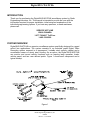
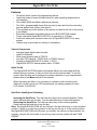
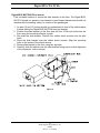
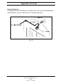
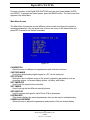
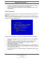
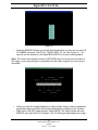
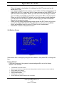
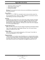
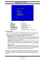
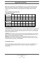
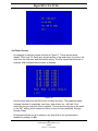
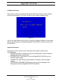
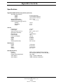
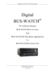
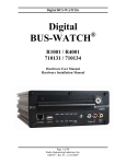
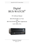
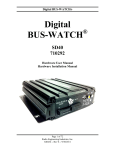
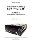
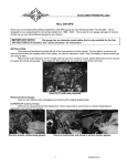
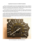
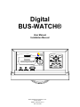
Digital
BUS-WATCH®
User Manual
Installation Manual
MENU CONTROL
EXIT
MENU
SEL
R
FUNCTION CONTROL
REW
STOP
Radio Engineering Industries, Inc.
6534 L Street
Omaha, Nebraska 68117
402-339-2200
PLAY
HEATER
FF
REC
Digital BUS-WATCH®
INTRODUCTION
4
SYSTEM OVERVIEW
4
FEATURES
5
System Components
5
Initial Set Up
5
Hard Drive Loading and Unloading
5
System Start-Up
6
Automatic Hard Drive Heater
6
Digital BUS-WATCH Security Cabinet
6
Long Term Storage
6
SYSTEM INSTALLATION
7
System Wiring
7
(Optional) BW Options Harness
8
Speedometer Harness
9
(Optional) BW Options Harness Wiring Instructions
10
On-Screen Information with (Optional) BW Options Harness
10
Physical Mounting Requirements
11
Digital BUS-WATCH® Hanging Mount (See Fig. 6)
12
Mount Conversion
Slide Bracket Modification (Figure 7)
Digital BUS-WATCH® Cabinet Modification (Figure 8)
13
13
13
Digital BUS-WATCH® Floor mount
14
Camera Placement
15
DIGITAL BUS-WATCH® BASIC OPERATION
16
FRONT PANEL
16
MENU SYSTEM
17
Main Menu Screen
18
Calibration Screen
19
Capture Image Screen
20
Set Options Screen
22
2
Radio Engineering Industries, Inc.
640289
Rev B -- 11/18/2002
Digital BUS-WATCH®
Set Time/Date Screen
25
Set Timers Screen
26
Set Route ID Screen
27
System Info Screen
27
Screen Adjustment Screen
28
DIGITAL BUS-WATCH® CD-ROM
29
SPECIFICATIONS
30
3
Radio Engineering Industries, Inc.
640289
Rev B -- 11/18/2002
Digital BUS-WATCH®
INTRODUCTION
Thank you for purchasing the Digital BUS-WATCH® surveillance system by Radio
Engineering Industries, Inc. This manual is intended to provide the user with the
information required for proper installation, initial setup and explanation of the
individual programming options. If you have any questions, or need assistance,
please call:
SERVICE HOT LINE
USA & CANADA
1-877-726-4617 Toll Free
1-402-339-2200
SYSTEM OVERVIEW
Digital BUS-WATCH® is a superior surveillance system specifically designed for rugged
school bus applications. The system consists of an industrial grade Digital Video
Recording system encased in a tamperproof, lockable steel security cabinet and a
surveillance camera of sturdy steel housing. As an option, the Digital BUS-WATCH®
can monitor and record vehicle functions such as warning lamp operation, brake,
vehicle speed, and two user defined points. Figure 1 shows each component and a
typical hookup.
Figure 1
4
Radio Engineering Industries, Inc.
640289
Rev B -- 11/18/2002
Digital BUS-WATCH®
Features
•
•
•
•
•
•
•
•
•
On screen menu system for programming options.
Hard drive heater to warm the hard drive to a safe operating temperature in
cold weather.
Non-volatile ROM and battery backed-up memory.
Ten 24-hr. programmable timers that are used to start and stop the recording
process without user (driver) intervention.
Time and date are at the bottom of the picture so detail at the top of the picture
is not hidden.
Electrically backward compatible with previous BUS-WATCH® models.
Power used while Digital BUS-WATCH is in operation is 18 Watts.
Audio and video jacks located on the front of Digital BUS-WATCH for easy
access.
Cabinet may be mounted in a variety of orientations.
System Components
• Industrial grade digital video recorder.
• Hard Drive Module.
• Slide mount bracket (part of 700814).
• Low light CCD camera - 700552 (live) or 700553 (decoy).
• Camera to Digital BUS-WATCH cable - 510781.
• Digital BUS-WATCH cabinet power cable - 510880.
Initial Set Up
The Digital BUS-WATCH® system will operate without any user setup with the
default settings, however, it may not show the correct time and date. To set the
correct date and time and to program the system operation to your requirements,
please refer to the Menu section of this manual.
When accessing the Menu, it is necessary to connect a video monitor to the
Video jack on the front of unit. REI recommends our battery-powered 2.9-inch
LCD monitor, P/N 690193.
Hard Drive Loading and Unloading
Inserting the Hard Drive: Turn the hard drive key to the unlocked position. Gently
insert the hard drive into the bay. Turn the hard drive key to the locked position.
Removing the Hard Drive: Turn the hard drive key to the unlocked position.
Gently remove the hard drive from the bay.
Note: The Digital BUS-WATCH® will not function if the hard drive key is in the unlocked
position. If there is no hard drive present in the bay but the key is in the locked position,
the Digital BUS-WATCH® will still power up normally, the menus can be accessed, etc.;
however, the unit will not be able to record any video and the screen will read "DISK
ERROR."
5
Radio Engineering Industries, Inc.
640289
Rev B -- 11/18/2002
Digital BUS-WATCH®
System Start-Up
To start the recording process, place the system switch in the ON position (this will
be done automatically if the system switch is connected to the ignition switch and
the ignition switch is in the ON position). Upon turning the system switch ON, the
Digital BUS-WATCH® will commence recording.
To stop the recording process, place the system switch in the OFF position. If the
OFF DELAY option is enabled, the Digital BUS-WATCH® will continue to record
for the prescribed number of minutes. When the off-delay expires, the camera and
Digital BUS-WATCH® shut off.
Automatic Hard Drive Heater
In order to prevent the possibility of hard-drive damage during cold periods, the
Digital BUS-WATCH® is equipped with a temperature sensor. The heater is
activated when the temperature at or below 40° F and the Digital BUS-WATCH®
is turned on via system switch or timer. This is indicated by the red LED labeled
HEATER on the front panel. The colder the temperature, the longer the heater
remains on, with a maximum of ten minutes at the coldest temperatures. During
this time all Digital BUS-WATCH® functions are inhibited and the camera remains
unpowered. When the unit has completed its heating cycle, it will power up and
operate normally.
Digital BUS-WATCH Security Cabinet
The Digital BUS-WATCH® security cabinet can be mounted in any orientation
under a seat, in a parcel rack, on the floor, to a wall, etc. It should not present a
trip hazard or head impact hazard, nor should it interfere with the seating, safety
or comfort of the passengers.
Long Term Storage
If the Digital BUS-WATCH® system is installed but not used for an extended
period of time (longer than 2 weeks) it is recommended that the main power toggle
on the front panel be set in the OFF position.
6
Radio Engineering Industries, Inc.
640289
Rev B -- 11/18/2002
Digital BUS-WATCH®
System Installation
WARNING
REMOVE VEHICLE BATTERY VOLTAGE BEFORE INSTALLING
SYSTEM WIRING
System Wiring
Note: All cables should be hidden from view.
For the basic system (shown in Fig. 2), there are two cables; power (510880) and
camera (510781). For additional vehicle monitoring, the BUS-WATCH® Options
harness (511617) is available.
Connect the camera using cable P/N 510781. There is no specific orientation for this
cable to be installed.
Connect power using cable P/N 510880. The black wire connects to the negative
terminal of the battery. The green wire (labeled 12V MEM) connects directly to the
positive terminal of the battery. The green wire should be fused at 4 A.
•
IF THE SYSTEM OPERATES IN THE MANUAL RECORD MODE, connect the
red wire (labeled 12V SW), to the switched side of the ignition switch. The red
wire should be fused at 1 A. The red wire is disabled if the system is in TIMER
record mode.
*Connect GREEN wire DIRECTLY
to the positive terminal of the
battery.
*Connect BLACK wire DIRECTLY
to the negative terminal of the
battery.
Figure 2
Note: Green wire fused @ 4 A, Red wire fused @ 1 A
7
Radio Engineering Industries, Inc.
640289
Rev B -- 11/18/2002
Digital BUS-WATCH®
(Optional) BW Options Harness
FROM
FLASHER
FROM
FLASHER
FROM
FLASHER
FROM
FLASHER
FROM
FLASHER
FROM BRAKE
PEDAL SWITCH
(Optional)
BW Options Harness
Figure 3
The BUS-WATCH® Options Harness (shown in Fig. 3) connects to various locations
in the vehicle to provide on-screen information regarding vehicle performance.
The monitored points in the vehicle are:
• Vehicle speed
• Brake activation
• Amber warning lamp operation
• Red warning lamp operation
• Stop arm lamp operation
• Optional points with AUX 1 & AUX 2 (Aux 1 & Aux 2 are user-defined and
may be used to monitor points such as turn signals, rear and front doors, etc.)
When using this option, the Digital BUS-WATCH® “learns” the off state of each
monitored point. To properly set polarity, all monitored points must be in the off
position upon when the Digital BUS-WATCH® is switched on.
(Optional) BW Options Harness Mounting Instructions
Install the BUS-WATCH® Option Harness (see Fig. 4) into the security cabinet.
1. Remove the four mounting screws connecting the tower to the slide bracket.
2. Remove the four screws holding the connector box to the tower.
8
Radio Engineering Industries, Inc.
640289
Rev B -- 11/18/2002
Digital BUS-WATCH®
3. Insert the BW Options Harness by snapping it into place.
4. Route the excess harness through the provided hole
5. Assemble the connector box back onto the tower. Observe proper alignment
of connector when inserting into box.
Figure 4
Speedometer Harness
Refer to the vehicle service manual for speedometer type, exact wire
location, and transmission manufacturer warnings.
The BUS-WATCH® speedometer input wires are designed to be spliced directly onto
the transmission speedometer transducer wires. In some installations, this may not be
possible (i.e. mechanical speedometer, transmission manufacturer warnings, etc.). The
BUS-WATCH® Vehicle Speed Sensor Kit (P/N 750086) may be required.
9
Radio Engineering Industries, Inc.
640289
Rev B -- 11/18/2002
Digital BUS-WATCH®
(Optional) BW Options Harness Wiring Instructions
WIRE COLOR
(2) YELLOW
(2) RED
BLUE
BROWN
WHITE
VIOLET
WIRE DESCRIPTION
RIGHT & LEFT YELLOW WARNING LAMP BANK
RIGHT & LEFT RED WARNING LAMP BANK
STOP ARM LAMP
BRAKE PEDAL LAMP
AUX SIGNAL 1
AUX SIGNAL 2
Yellow Warning Lamps
Connect the YELLOW wires to each of the Warning Lamp Flashers’ Yellow lamp
outputs.
Red Warning Lamps
Connect the RED wires to each of the Warning Lamp Flashers’ Red lamp outputs.
Stop Arm Lamps
Connect the BLUE wire to the switched side of the top stop arm lamp.
Brake Lamp
Connect the BROWN wire to the switched side of one brake lamp.
On-Screen Information with (Optional) BW Options Harness
The Digital BUS-WATCH® Surveillance system, when equipped with the BW Option
Harness, will display information on-screen when the vehicle’s monitored switches are
activated and signals are applied to the monitored sensors.
ACTIVE SWITCH OR SIGNAL
BRAKE APPLIED
STOP ARM DEPLOYED
LEFT YELLOW WARNING LAMPS ON
(SEE NOTE 1)
RIGHT YELLOW WARNING LAMPS ON
(SEE NOTE 1)
LEFT RED WARNING LAMPS ON
(SEE NOTE 1)
RIGHT RED WARNING LAMPS ON
(SEE NOTE 1)
SPEEDOMETER
(SEE NOTE 2)
ON-SCREEN DISPLAY
B
S
*Y
Y*
*R
R*
XX
MPH
NOTES:
1.
2.
The “*” symbols will alternately appear on each side of the “Y” or “R” in concert with the active lamp
bank.
The XXs represent the vehicle speed (i.e. 35).
10
Radio Engineering Industries, Inc.
640289
Rev B -- 11/18/2002
Digital BUS-WATCH®
Physical Mounting Requirements
There are two common ways to mount the
Digital BUS-WATCH®. First is the under-seat,
or hanging, method. This method mounts the
slide bracket to the underside of a seat.
Second is the floor-mount method. This method
mounts the Digital BUS-WATCH® to the floor
of the bus. Figure 5 shows the minimum area
for the system installation.
Figure 5
11
Radio Engineering Industries, Inc.
640289
Rev B -- 11/18/2002
Digital BUS-WATCH®
Digital BUS-WATCH® Hanging Mount (See Fig. 6)
1. Find a suitable location under the first seat behind the driver or under
the drivers seat.
2. An area 15-1/2 inches should be unobstructed in front of the slide
bracket to allow sliding the security cabinet onto the slide bracket.
3. If necessary modify the positions of the tower, connector box, and
slide rails according to the instructions above.
4. Position the slide bracket on the frame of the seat in the desired
location. Drill 5/16th inch holes through the frame using the bracket as
a guide.
5. Attach slide bracket to seat frame using nuts and bolts.
Figure 6
12
Radio Engineering Industries, Inc.
640289
Rev B -- 11/18/2002
Digital BUS-WATCH®
Mount Conversion
Slide Bracket Modification (Figure 7)
1. Remove tower from slide bracket using four cap screws.
2. Slide tower to other side of bracket.
3. Reattach tower to slide bracket using four cap screws.
4. Remove connector box from tower using four screws.
5. Rotate connector box such that the rubber grommet is on the outside
edge of the tower.
6. Reattach connector box to tower using four screws.
2
2
1
1
Figure 7
Digital BUS-WATCH® Cabinet Modification (Figure 8)
Reverse the placement of the slide rails with screws and washers from top to
bottom of the Digital BUS-WATCH®.
Figure 8
13
Radio Engineering Industries, Inc.
640289
Rev B -- 11/18/2002
Digital BUS-WATCH®
Digital BUS-WATCH® Floor mount
Find a suitable location to mount the slide bracket on the floor. The Digital BUSWATCH should not present a trip hazard or head impact hazard and should not
interfere with the seating, safety, or comfort of the passengers.
1. An area 15 and 1/2 inches should be unobstructed in front of the slide bracket
to allow sliding the Digital BUS-WATCH® onto the bracket.
2. Position the slide bracket on the floor and drill four 3/16th inch holes into the
floor using the mounting holes as a guide.
3. Set aside the slide bracket. Position four rubber shock mounts over the pilot
holes.
4. Place the slide bracket over the rubber shock mounts. Align the mounting
holes to the center of the shock mounts.
5. Secure slide bracket to the floor using four lag bolts.
6. Carefully slide the cabinet onto the slide bracket being sure to check alignment
of the connector. Lock to secure.
Figure 9
14
Radio Engineering Industries, Inc.
640289
Rev B -- 11/18/2002
Digital BUS-WATCH®
Camera Placement
The Digital BUS-WATCH® camera is mounted to the center of the front header panel,
unless this does not give a stable mount or it vibrates excessively.
Fig. 10
15
Radio Engineering Industries, Inc.
640289
Rev B -- 11/18/2002
Digital BUS-WATCH®
Digital BUS-WATCH® Basic Operation
The Digital BUS-WATCH® functions somewhat like a VCR, except that the recorded
video is stored on the hard drive, rather than on a video tape. To view the recorded
video or to access the MENU functions, connect a monitor to the Digital BUS-WATCH®
using the front jacks labeled AUDIO and VIDEO. The end user supplies the monitor and
the cable to connect the monitor. The Digital BUS-WATCH has several modes of
operation.
SLEEP mode: In a mobile, battery-powered application, it is critical to minimize power
consumption to prevent draining the vehicle battery, therefore, whenever the unit is not
recording, it automatically enters SLEEP mode. In SLEEP mode, the unit's power
consumption is minimal. The red LED on the Power Switch on the front panel is off
when the unit is in SLEEP mode.
RECORD mode: While the unit is actively recording video, it is in RECORD mode. The
red LED on the Power Switch is on, and the green LED near the REC button is on. The
unit can be placed in RECORD mode in one of three ways: system switch,
programmable timer, and pressing the REC button.
PLAYBACK mode: While the unit is playing back recorded video, it is in PLAYBACK
mode. The red LED on the Power Switch is on. When the unit is PLAYBACK, the onscreen display will read PLAY and either "(-" or "-)". This indicates the direction the
video is playing, forward or backward. The direction can be switched by the FF or REW
buttons.
MENU mode: The MENU mode can be activated any time the Power Switch is turned
on by pressing the MENU button. In the MENU mode, the unit's settings and options
can be accessed. The MENU mode operations are described below. If the unit is
RECORDING, it records all MENU operations.
MONITOR mode: When the Digital BUS-WATCH is active, but not in RECORD,
MENU, or PLAYBACK mode, it is in MONITOR mode. The live video from the VIDEO
input is displayed on the monitor.
Front Panel
The user controls the functions of the Digital BUS-WATCH with the buttons on the front
panel. (See Figure 11)
16
Radio Engineering Industries, Inc.
640289
Rev B -- 11/18/2002
Digital BUS-WATCH®
Figure 11
Controls:
•
•
•
•
•
•
•
•
•
MENU - Brings up the System Control menu.
EXIT - Exits the current menu or function.
SEL - Selects the current menu setting. Functions much like an
ENTER key. If the unit is in SLEEP mode, pressing this button causes
it to wake up and enter RECORD mode. If the SYSTEM SWITCH is
off, pressing this button again puts the unit back into SLEEP mode.
Directional Arrows - These buttons are used to navigate the menus.
PLAY - Plays back recorded video. Begins playback at the last recorded
image.
REC - Starts recording. Recording is indicated a green LED near this button.
STOP - If the unit is recording, this button stops the recording. If the unit is
playing, this button acts as a PAUSE. Pressing this button while PAUSED
stops all playback and puts the unit in Monitor Mode.
FF - If the unit is playing, this button FAST FORWARD SCANS through the
recorded video. Pressing this button several times increases the scanning
speed.
REW - If the unit is playing, this button REWIND SCANS through the
recorded video. Pressing this button several times increases the scanning
speed.
Menu System
The menu system allows the user to set and save the system operating parameters.
17
Radio Engineering Industries, Inc.
640289
Rev B -- 11/18/2002
Digital BUS-WATCH®
Connect a monitor to the Digital BUS-WATCH® using the front jacks labeled AUDIO
and VIDEO. To activate the menu system, press the MENU button. The first screen that
appears is the Main Menu.
Main Menu Screen
The Main Menu Screen has several different options used to configure the system's
operating parameters. Use the arrow keys to move the cursor to the desired line and
press SEL to execute the desired command.
Figure 12
CALIBRATION
Allows the user to calibrate the speedometer and voltmeter functions.
CAPTURE IMAGE
Used when downloading digital images to a PC via the serial port.
SET OPTIONS
Where the user configures many of the system's operating parameters, such as
recording options, on-screen display options, off-delay, and others.
SET TIME/DATE
Used to set the system's time and date.
SET TIMERS
Used to set up the ten different recording timers.
SET ROUTE ID
Used to program this specific unit's Route ID # or description.
SYSTEM INFO
This screen displays the several parameters than can be used in troubleshooting.
SCREEN ADJUSTMENT
Allows the user to adjust the appearance and position of the on-screen display.
18
Radio Engineering Industries, Inc.
640289
Rev B -- 11/18/2002
Digital BUS-WATCH®
Calibration Screen
This submenu screen has two different options, Speedometer Calibration, and Voltage
Calibration.
Note: To use these functions, you must have the DISPLAY OPTIONS set to display the
Speedometer and/or the Voltage.
SPEEDOMETER CALIBRATION
Because speedometers can vary greatly among bus manufacturers, the Digital
BUS-WATCH® has the ability to calibrate its own speedometer to that of the bus.
Follow this procedure to calibrate the speedometer:
• Drive the bus at a known and constant speed, such as 30 mph.
• Bring up the Speedometer Calibration Screen. The screen will display what the
Digital BUS-WATCH® system perceives as the vehicle's speed.
• Use the UP and DOWN arrow keys to adjust the displayed speed to match that
the vehicle's speedometer. This might require many keypresses.
• When the speeds match, press EXIT to save the calibration and return to the
previous menu. The displayed speed will now match that of the vehicle.
Figure 13
VOLTAGE CALIBRATION
It is sometimes useful, mainly for troubleshooting purposes, for the Digital BUSWATCH® to record the voltage on the power system of a bus. The unit has a
voltage sensor that can record the current voltage supplied to the unit by the bus.
However, the wiring systems of buses often vary greatly among manufacturers, so
the Digital BUS-WATCH® has the ability to calibrate its own voltmeter. Follow this
procedure to calibrate the voltmeter:
• Use a handheld voltage meter to sense the voltage supplied to the power inputs
of the Digital BUS-WATCH®.
• Bring up the Voltage Calibration Screen. The screen will display what the Digital
BUS-WATCH system perceives as the voltage supplied.
19
Radio Engineering Industries, Inc.
640289
Rev B -- 11/18/2002
Digital BUS-WATCH®
•
•
Use the UP and DOWN arrow keys to adjust the displayed speed to match that
the hand-held voltmeter. This might require many keypresses.
When the voltages match, press EXIT to save the calibration and return to the
previous menu.
Capture Image Screen
This submenu screen is used when you wish to download a still image to a PC via the
serial port.
Note: As with all MENU functions, you must have a video monitor connected to the
VIDEO OUT jack on the Digital BUS-WATCH. Live video images cannot be transferred
directly to PC through the serial cable.
Figure 14
The procedure to download an image from the Digital BUS-WATCH® is as follows.
•
•
•
•
•
•
Connect the serial cable from the PC to the jack on the front of the Digital BUSWATCH®.
On the PC, open and run the REI Viewer software. (The software must be
installed in advance.) The PC is now waiting to download an image.
Press MENU to bring up the Main Menu.
Select CAPTURE IMAGE.
Select DOWNLOAD IMAGE NOW. The video switches from the MENU to the
current PLAYBACK image. Control of the PLAYBACK is now shared between the
unit's front panel and your PC.
On the PC, right-click in the REI Viewer window. This brings up a function menu.
See Figure 15.
20
Radio Engineering Industries, Inc.
640289
Rev B -- 11/18/2002
Digital BUS-WATCH®
Figure 15
•
Selecting REMOTE brings up a virtual control panel that you can use to control all
PLAYBACK functions, from PLAY, PAUSE, REW, FF, etc. See Figure 16. You
can still use the buttons on the Digital BUS-WATCH to control video playback.
Note: The virtual control panel includes a RECORD button. Do not press this button at
this stage, or you may damage or completely lose the video image(s) you are trying to
download!
Figure 16
•
•
When you have the image displayed on video monitor that you want to download,
pause that image, and close the virtual control panel by clicking on the X button.
Right-click in the REI Viewer window. Select READ. The video monitor will read
BACKUP up under the PLAY indicator. The PC will begin downloading the image.
21
Radio Engineering Industries, Inc.
640289
Rev B -- 11/18/2002
Digital BUS-WATCH®
•
•
•
When the image is downloaded, it is displayed on the PC screen and can be
saved as a PC file.
If you want to download more images, you can either use the control panel on the
Digital BUS-WATCH or right-click on the Viewer window and click REMOTE to reopen the virtual control panel. Before you can move to the next image, however,
you must either press STOP on the virtual control pad or SEL on the front panel.
When you do this, the BACKUP indicator on the video screen should disappear.
You can then move the video image to the next image you want to download.
Repeat the two previous steps.
When your are finished downloading images, press the EXIT button on the front
panel of the Digital BUS-WATCH. This switches the unit back into the MENU
mode, and transfers control from the PC back to unit's control panel.
Press EXIT to return to the previous menu.
Set Options Screen
Figure 17
Select which item to change by using the arrow buttons, then press SEL to change the
item.
Factory Default
If this item is selected, the system's internal settings will be set to the factory
defaults. This includes:
•
•
•
•
•
•
•
Total Record Time reset to zero.
Minimum and maximum temperature and voltage data erased and reset to current conditions.
Record Mode set to Manual
Daylight Savings Time enabled.
24-hour Mode disabled.
Off Delay set to 16 minutes.
Screen width and position settings reset to defaults.
22
Radio Engineering Industries, Inc.
640289
Rev B -- 11/18/2002
Digital BUS-WATCH®
•
•
•
•
Speedometer calibration reset to default.
Voltage calibration reset to default.
Route ID reset to "REI001".
All Timers set to defaults.
Warning: Do not select this function unless you want all settings changed back to
their factory defaults!
Record Mode
When set to 'T,' or TIMED, the command to start or stop recording comes from
the programmable timers. When set to 'M,' or MANUAL, the command to start or
stop recording comes from the System Switch.
Off Delay
Can be set to any number from 0 to 35. This is the number of minutes the Digital
BUS-WATCH® will continue to record after the System Switch has been turned
off. The default for this setting is 16 minutes. Note: This function only works in
MANUAL Record Mode (see below). Off delay is not used if the unit is configured
to use the programmable timers.
Daylight Savings Time
When set to Yes, the system clock will change automatically with Daylight Savings
Time. If your region does not use Daylight Savings Time, this function may be
disabled by setting this item to No.
24-Hour Mode
When set to Yes, the clock will be displayed in a 24-hr format. If set to No, the
clock will be displayed in a 12-hr. format.
Display Options
This item takes you to another screen that allows you to customize what is shown
on this unit's on-screen display. An asterisk beside the item indicates that the item
in question will be shown on-screen during normal operation. Pressing the SEL
button when the cursor is set to a particular line toggles the asterisk on or off.
23
Radio Engineering Industries, Inc.
640289
Rev B -- 11/18/2002
Digital BUS-WATCH®
Figure 18
•
•
•
•
•
•
•
TIME
CALENDAR
ROUTE ID
VOLTAGE
TEMPERATURE
SPEEDOMETER
SENSOR DATA
Current time.
Current date.
Programmable Route ID.
System voltage.
Temperature inside cabinet.
Bus Speedometer.
Warning lights, brakes, stop-arm, etc.
Recording Options
This item takes you to another screen that allows you to access the options that
relate to the recording quality. Use the arrows and SEL buttons to select the items
as desired. The recording quality of the Digital BUS-WATCH® has three
independent settings: REC MODE, REC FPS, and REC QUALITY.
• REC MODE: Can be set to either FRAME or FIELD. This sets whether the unit is
recording video fields, or full frames. Frames require more disk-space per image,
so they reduce recording time but provide a better quality image. Fields reduce
video quality but increase recording time.
• REC FPS: Has several different options, ranging from 0.5P to 60P. The number
equates to fields or frames per second. For real-time video with accompanying
audio, this must be set to 60P. At any setting less than 60P, the audio recording
does not function.
• REC QUALITY: This setting corresponds to the compression ratio of the video
data. There are three options: HIGH, NORMAL, and LOW. HIGH gives the best
quality image but reduces the length of recording time. LOW gives the longest
recording time, but the recorded image quality is reduced slightly.
These three settings all have an significant effect on recording capacity of a given hard
drive. Below is a chart giving the approximate recording capacity of a 20GB drive at
each of the above settings. Drives of larger sizes have proportionally larger recording
capacities.
24
Radio Engineering Industries, Inc.
640289
Rev B -- 11/18/2002
Digital BUS-WATCH®
Note: These numbers can vary significantly with a color vs. black-and-white camera,
frame composition, and light level. This table is representative of a color camera. A
system using a black and white camera generally has a slightly higher recording
capacity.
Hours of Recording Time with
a 20 GB hard drive
Quality
FPS
Low
Normal
High
Quality
FPS
Low
Normal
High
Field
Frame
Field
Frame
Field
Frame
Field
Frame
0.5P
2760
1376
896
0.5P
1380
690
448
1P
1376
690
448
1P
690
345
224
2P
690
344
224
2P
345
172
112
4P
345
172
112
4P
172
86
56
Field
Frame
Field
Frame
Field
Frame
Field
Frame
8P
172
86
56
8P
86
43
28
15P
86
46
30
15P
46
23
15
30P
46
23
15
30P
23
11.5
7.5
60P
23
11.5
7.5
60P
11.5
5.75
3.75
AUTOREVERSE: When this function is set to ON, the Digital BUS-WATCH® will record
continuously. When the hard drive is full, the recording "loops" around to overwrite the
oldest data as it records new data. When this function is set to OFF, the recording will
stop when the hard drive is full.
CLEAR HD: This function is used to erase all the video information stored on the hard
drive. To do this, set the function to ON, then exit the Recording Options menu. Upon
exiting the menu, the hard drive will be erased.
Warning: Executing this command is irrevocable! Do NOT set this function to ON
unless you are sure. Once it is completed, the unit will be unable to access any video
information previously stored on the hard drive.
Set Time/Date Screen
Use the arrow buttons to step through the month, day, and year. The weekday is set
automatically. Repeat this with the hours, minutes, and seconds. AM/PM is set
automatically.
25
Radio Engineering Industries, Inc.
640289
Rev B -- 11/18/2002
Digital BUS-WATCH®
Figure 19
Set Timers Screen
An example of the timer screen is shown in Figure 17. There are ten timers,
labeled T0 through T9. Each timer shows the day of the week when it is active, the
start time, the stop time, and the Enable setting. The Yes means that this timer is
enabled. A No indicates that the timer is disabled.
Figure 20
Use the arrow keys and the SEL button to select the timer. The parameter being
changed, whether it is weekday, start hour, stop minute, etc., will flash. First,
select the day you wish this timer to operate. You can choose any day of the week
or the "MF" setting, which causes the timer to work on every weekday, Monday
through Friday.
All timers should be set up in advance. Any timer that is not used should be
disabled by setting it to No.
26
Radio Engineering Industries, Inc.
640289
Rev B -- 11/18/2002
Digital BUS-WATCH®
Set Route ID Screen
This screen is used to set the Route ID that will be shown on the on-screen display
during normal operation. The Route ID can be up to sixteen characters long.
Figure 21
Use the UP and DOWN arrow buttons to change the flashing character to the desired
setting. Each character is changed individually. Press RIGHT or SEL to move to the
next character.
System Info Screen
This screen is used to show various information that might be useful during
troubleshooting.
• SPEEDO FACTOR: A number used by the microprocessor control software to
calibrate the internal speedometer.
• RECORD TIME: Total number of hours the Digital BUS-WATCH® unit has
recorded video footage.
• SYSTEM VOLTAGE: Minimum and maximum readings of the bus system
voltage.
• ENCLOSURE TEMPERATURE: Minimum and maximum readings of the
temperature within the Digital BUS-WATCH® cabinet.
27
Radio Engineering Industries, Inc.
640289
Rev B -- 11/18/2002
Digital BUS-WATCH®
Screen Adjustment Screen
This screen is used to adjust the position and width of the on-screen display, using the
arrows and the SEL buttons.
There is an 'X' in each corner of this screen to make it easy for the user to center the
display in the monitor.
Figure 22
Center On-Screen Display
Use the arrow buttons to center the four 'X's in the screen. Pressing MENU resets
this setting to the factory defaults. When finished, press EXIT to save the settings.
Adjust Width
Use the left and right arrow buttons to change the width of the on-screen display.
Pressing MENU resets this setting to the factory defaults. When finished, press
EXIT to save the settings.
28
Radio Engineering Industries, Inc.
640289
Rev B -- 11/18/2002
Digital BUS-WATCH®
DIGITAL BUS-WATCH® CD-ROM
The CD-ROM contains:
•
•
An electronic copy of this manual in PDF format. It requires Adobe Acrobat
Reader®.
The REI Viewer Software, which is used when downloading images to a PC from
the Digital BUS-WATCH.
Downloading images to a PC via the serial cable requires the REI Viewer Software.
This software must be installed on the PC before attempting to download any images.
To install the software:
• Insert the CD-ROM into the drive.
• Using Windows Explorer or My Computer, view the contents of the CD-ROM
drive. Double-click the file named SETUP.EXE. The software will install
automatically.
NOTE: In some PCs that use Windows 95 or Windows 98, some of the PC's system
files may be outdated. The installation of the REI Viewer software will recognize if this is
the case, and attempt to update those files. For the REI Viewer software to function,
you must allow the installation to update those files.
29
Radio Engineering Industries, Inc.
640289
Rev B -- 11/18/2002
Digital BUS-WATCH®
Specifications
Digital BUS-WATCH® Security Cabinet (main unit)
Size (with slide bracket)
Height
6 inches maximum
Width
11-1/4 inches maximum
Depth
15-1/2 inches maximum
Weight (with bracket)
22 lb. 13 oz.
Weight (without bracket)
17 lb. 11 oz.
Power Consumption (@ 12V DC)
Standby
15 mA
Recording
1.5 A
Heater
2.5 A
Camera
Image device
Focal length
Angle of view (D x H x V)
Illuminance Sensitivity
Electronic Iris
Power Supply
Power consumption
Height
Width
Depth
Weight (with bracket)
1/3 inch
8 mm
40.1’ x 32.6’ x 24.7’
0.1 Lux
1/100,000 sec
12V
145 mA
3 inches
3 inches
3 inches
20.7 ounces
Slide Bracket
Height
Width
Depth
Weight
1.23 inches
9.76 inches
13.34 inches
4 lb. 14 oz
DVR Specifications
Format
Resolution
Playback Scanning Speed
Video Output
Audio Output
NTSC or PAL Standard (Factory Setting)
720 x 525 pixel (NTSC) or 720 x 520 (PAL)
Up to 600x
1Vp-p, 75 Ohm unbalanced
-5dBm, 600 Ohm unbalanced
30
Radio Engineering Industries, Inc.
640289
Rev B -- 11/18/2002