1
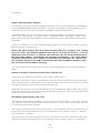
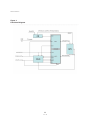
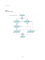
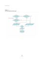
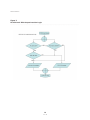
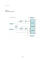
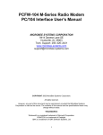
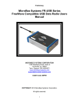
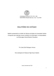
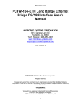
preliminary
COPYRIGHT 2011 MicroBee Systems Corporation.
MBS-GPS Novatel SSII & OEMV-1 PC/104 GPS Module
User’s Manual
CAGE Code 3DPE9
ALL RIGHTS RESERVED
However, any part of this document may be reproduced, provided that MicroBee Systems Corporation is cited as the source. The contents of this manual and the specifications herein may
change without notice.
TRADEMARKS
Windows® is a registered trademark of Microsoft Corporation.
ROM-DOS is a trademark of Datalight.
QNX is a trademark of QNX Software Systems, Ltd
......................................................................................................................................
MICROBEE SYSTEMS CORPORATION
1429 Weatherly Road, Suite G
Huntsville, AL 35803
Tech. Support: 256–489-6671
www.microbee-systems.com
[email protected]
1
REV B
preliminary
NOTICE TO USER
. . . . . . . . . . . . . ............................................................................................. . . . . .
The information contained in this manual is believed to be correct. However, MicroBee Systems assumes no responsibility for any of the circuits described herein, conveys no license
under any patent or other right, and makes no representations that the circuits are free from
patent infringement. MicroBee Systems makes no representation or warranty that such applications will be suitable for the use specified without further testing or modification.
MicroBee Systems Corporation general policy does not support the use of its products in life
support applications where the failure or malfunction of a component may directly threaten
life or injury. It is a Condition of Sale that the user of MicroBee Systems products in life support applications assumes the risk of such use and indemnifies MicroBee Systems against all
damage.
Please read before installing your product
MicroBee’s products are designed to be high in performance while consuming very little
power. In order to maintain this advantage, CMOS circuitry is used. CMOS chips have specific
needs and some special requirements that the user must be aware of. Read the following to
help avoid damage to your card from the use of CMOS chips.
Using CMOS Circuitry
Industrial Control originally used LSTTL circuits. Because many PC components are used in
laptop computers, IC manufacturers are exclusively using CMOS technology. Both TTL and
CMOS have failure mechanisms, but they are different. This section describes some of the
common failures which are common to all manufacturers of CMOS equipment.
Improper power causes catastrophic failure
If a card has had reverse polarity or high voltage applied, replacing a failed component is not
an adequate fix. Other components probably have been partially damaged or a failure mechanism has been induced. Therefore, a failure will probably occur in the future. For such cards,
MicroBee highly recommends that these cards be replaced.
Other over-voltage symptoms
In over-voltage situations, the programmable logic devices, EPROM’s and CPU chips, usually
fail in this order. The failed device may be hot to the touch. It is usually the case that only one
IC will be overheated at a time.
Hot insertion
Hot insertion is not supported. Doing so voids your warranty.
2
REV B
preliminary
PREFACE
. . . . . . . . . . . . . ............................................................................................. . . . . .
This manual is a guide to the proper configuration, installation, and operation of your MBSGPS PC/104 Interface. For setup and operation of the Novatel SSII or OEMV-1 Manuals included with this product. You can use your MBS-GPS-SS2-5HZ card in conjunction with other
PC/104 expansion cards, tailoring your system for a wide variety of applications.
TECHNICAL SUPPORT
. . . . . . . . . . . . . ............................................................................................. . . . . .
MicroBee Systems is committed to supporting our products. For this reason all user manuals
as well as this manual are always available online in PDF format at http://www.microbee-systems.com/user_manuals.htm. If you do not find this online then please inform us and we will
make it available immediately.
This unit has been tested with a number of operating systems including MSDOS, Linux, QNX,
Microsoft Windows 98, NT, 2000 and XP. Any operating systems supporting an ISA legacy
device should operate normally with this product. This unit defaults to 16C550 mode. Access
to advanced features are via register access or jumpers and thus may require modification to
existing drivers. MicroBee Systems does not guarantee operation with unusual or custom “in
house” operating systems or serial IO libraries. We will help you all we can.
If you have a question about the MBS-GPS card and cannot find the answer in this manual, call
Technical Support. They will be ready to give you the assistance you need.
When you call, please have the following at hand:
•
•
Your MBS-GPS Module Interface User’s Manuals
A description of your problem.
The direct line to Technical Support is 256-426-2431.
OVERVIEW
. . . . . . . . . . . . . ............................................................................................. . . . . .
The MBS-GPS PC/104 GPS Module is a CPLD based triple high speed 16C850 UART PC/104
Bus Compliant 8 BIT interface based upon the Exar XR16C2850 Dual UART with user selectable 128 Byte deep FIFO buffers and integrated with the Novatel Super Star II 5Hz GPS. This
interface provides two independent user inversion selectable TTL and RS232 level 1PPS outputs. Serial Port 1 is used as the Primary Data/Command Port and Port 2 is the Differential input when a RTCM compliant correction message is supplied. Port 3 is a standard high speed
serial port available for communications up to 921 kBaud.
This unit is available with either the Novatel SSII 3.3V GPS or the high performance Novatel
3
REV B
preliminary
OEMV-1 3.3V GPS.
Once the unit is configured and installed it is treated as three standard serial ports on the
PC/104 stack. As an example, if the Data Port is configured for an address of 0x3F8 and IRQ
4 then the MBS-GPS is utilized simply as COM 1. Default operation is 16C550 mode with 16
byte FIFO’s. Wide FIFO enable is via software writes to special registers. Please refer to the
XR16C2850 UART datasheet. This unit does not support flow control except on the EXT Serial Port.
The interface supports baud rates up to a maximum of 921,600 Baud. However, the Novatel
SSII only supports maximum rates of 19,200. Operation with 16 byte FIFO’s is satisfactory at
this rate. However, the user can enable FIFO’s up to 128 bytes deep. This means that instead
of an interrupt generated every 15 characters one could be generated only once per message
greatly reducing overhead on the host processor to handle interrupt servicing.
The unit incorporates the 16 bit PC/104 ISA connector so 16 bit devices can be placed on the
stack after the radio. Also interrupts 10, 11, 14 and 15 are accessed thru this connector. The
MBS-GPS-SS2-5HZ, being an 8 BIT interface, does not require a 16 bit ISA card be prior to the
radio unless operation requires IRQ 10, 11, 12, 14 or 15.
For more information on the PC-104 ISA bus please refer to the PC-104 specification at:
http://www.pc1 04.org/technology/PDF /PC1 04Specv246.pdf
Caution
The MBS-GPS contains static sensitive CMOS components. The greatest danger occurs when
the card is plugged into the PC/104 stack. The card becomes charged by the user and the
static discharges to the I/O bus from the pin closest to the card connector. If that pin happens
to be an input pin, even TTL inputs may be damaged. Follow sound ESD practices!!!!
To avoid damaging your card and its components:
Ground yourself before handling the MBS-GPS Module.
Disconnect power before removing or inserting the MBS-GPS Module.
OPERATING PRECAUTiONS + TECHNICAL SPECIFICATIONS
. . . . . . . . . . . . . ............................................................................................. . . . . .
Ordering Information
Part # MBS-GPS-SSII-5Hz with the Super Star 2 5 Hz OEM GPS.
Part # MBS-GPS-OEMV-1 with the Novatel OMEV-1 OEM GPS.
No REV # is required.
Baud Rate
The MBS-GPS is fully 16C850A compliant and supports software selectable baud rates up to
4
REV B
preliminary
921,600 baud.
The Novatel SSII-5Hz supports a maximum of 19,200 baud. The OEVM-1 supports up to
921,600 baud.
Environmental
-35° to 70° C operating.
-40° to 90° C non-operating.
RH 5% to 95%, non-condensing.
Power Specification
5V +/– 5% at 100 mA maximum..
Antenna common mode output 50mA Maximum.
Size
3.6 in. x 3.8 in x 0.5 in.
91.4 mm X 96.5 mm x 15.2 mm
INSTALLATION
. . . . . . . . . . . . . ............................................................................................. . . . . .
Before installing the MBS-GPS Module, refer to Figure 1 for the location of various rotary
switches, connectors and jumpers.
Interrupt Selection Switches, SW4, SW8, SW12
The MBS-GPS uses simple and easy to use rotary switches for IRQ selection. Simply place the
serial port IRQ switch to the desired setting you want. If you select an invalid IRQ then interrupts are disabled for that port. IRQ’s 3, 4, 5, 6, 7, 9, 10, 11, 12, 14 and 15 are supported. Thus
if you select IRQ 1, 2, 8, 13 there is no IRQ enabled for that port. The CPLD simply ignores
invalid selections. These can be used for polled mode operation.
Simply select the desired IRQ level by rotating the IRQ Selection switch the appropriate position (see Figure 1).
Default configuration shown in Figure 1 for SW4 is IRQ4 which is standard for COM1. Default
configuration for SW8 is IRQ3 which is standard for COM 2. Each port must use a unique IRQ.
Caution
Improper IRQ configuration can result in your CPU locking up due to an IRQ conflict. Most
COM libraries allow for non-standard IRQ settings as will after market drivers. Windows 95,
98, ME, NT, 2000 and XP may limit your IRQ selection without aftermarket drivers. This is
usually not required unless all IRQ’s supported by the OS are already allocated.
5
REV B
preliminary
Address Selection Rotary Switches
For flexibility with most SW and Development libraries this unit will support any valid address
between 0x000-0x007 and 0x7F8-0x7FF. However, most platforms have limited IO space.
Please refer to your host CPU IO Map for available IO space for this product.
Most applications will use one of the common serial port addresses. The most common are:
COM1 = 3F8, IRQ4, COM2 = 2F8, IRQ3 COM3 = 3E8, IRQ4 COM4 = 2E8, IRQ3. Figure 1 shoes
0x3f8 for the GPS Data Port, 0x2f8 for the GPS Differential Port and 0x300 for the External
Serial Port.
This unit is simple to use. Set the selected channel address switches to the IO space you want
and the channel is ready to use.
Please note, when selecting the LSB of each serial port only bit 3 is changed. Thus a setting
of 0 or 8 is valid. Any selection between 0 and 7 (BIT 3 = 0) and 8 and 15 (BIT 3 = 1) has no
effect other than to set BIT 3. Confused? This means BIT’s 0-2 are masked and have no effect on the base address. ISA IO blocks are assigned in 8 byte blocks. Thus a base address
of 0x3f0 or 0x3f8 makes sense. However, a base address of 0x3f9 does not. Address bits
0-2 are routed directly to the UARTS and are not used in base IO address decoding. Only
bits 3 to 15 are used for address decoding.
So if you set the rotary switches to an IO space of 0x3f9 the device still maps to a base IO of
0x3f8.
Internal or Auxiliary 1 Pulse Per Second (1PPS) Selection, JP1
JP1 Controls the 1PPS source and HW or SW control of the source.
In position SW the 1PPS signal is routed based upon the level of the RTS line of the Data Port.
Thus if the data port is COM1 (0x3F8) then setting the RTS bit of COM1 to 1 will select the AUX
PPS input and setting the RTS bit to 0 will select the GPS.
In position JP the data, PPS signal and Reset lines are routed based upon Jumper JP1, not the
RTS bit of the Data Port. JP1A GPS selects the Novatel SSII for the 1PPS source and JP1A AUX
selects the AUX for the 1PPS source.
PPS Output Signal Inversion, JP2 & JP3
There are two PPS Outputs available. One is RS-232 level and the other is TTL Level. JP2 and
JP3 control the inversion of the respective PPS outputs as well as allow either jumper settings
or software control of the inverters.
JP2 controls the RS-232 level inversion exclusively. The SW position allows inversion to be set
by the RTS1 BIT of the Differential Port. The JP position selects jumper control. N = Normal
or Un-Inverted, I = Inverted.
JP3 controls the TTL level inversion exclusively. The SW position allows inversion to be set by
the RTS1 BIT of the Differential Port. The JP position selects jumper control. N = Normal or
6
REV B
preliminary
Un-Inverted, I = Inverted.
RTS1
Inverts or un-inverts the RS-232 1PPS signal output. Bit set = invert.
DTR0
Inverts or un-inverts the TTL 1PPS signal output. Bit set = invert.
STATUS MONITORING
. . . . . . . . . . . . . ............................................................................................. . . . . .
Overview
Several status features are available. These are provided to monitor the 1PPS timing pulse
from either the GPS or the AUX 1PPS source. The 1PPS is primarily used for synchronization of
MicroBee Systems PC/104 FreeWave data radio products in Masterless TDMA mode and Push
To Talk (PTT) mode. In addition the 1PPS is very useful for timetag and system synchronization functions by providing a very precise time mark. For these reasons advanced features
allow an AUX PPS, primarily for software development without a valid GPS signal, and polarity
inversion of the signals should a system/device require this.
Additionally the 1PPS output is available in both TTL and RS-232 Levels. Please refer to the
section on J6 for further information.
DSR0
of the Data Port monitors the GPS 1PPS or AUX before the 1PPS inversion capabilities. In
other words, this is direct from the GPS or AUX.
RI0
of the Data Port monitors the 1PPS before the inversion circuitry. Comparison of this BIT can
be used to help verify inversion is set.
RI1
of the Diff Port monitors the RS-232 1PPS after the inversion circuitry. If the 1PPS is noninverted then this will be identical to DSR0 & RI0. If inversion of the 1PPS is selected then this
will be the compliment of DSR0 & RI0.
CD0
of the Data Port monitors the TTL 1PPS after the inversion circuitry. If the 1PPS is non-inverted
then this will be identical to DSR0 & RI0. If inversion of the 1PPS is selected then this will be
the compliment of DSR0 & RI0.
CTS0
of the Data Port is used to monitor the AUX PPS in. If the AUX PPS is unused then this should
be ignored. This is used to monitor for the presence of an AUX PPS signal.
7
REV B
preliminary
NOTE
If AUX PPS is selected then the these features will work upon the AUX signal instead of the
GPS signal. The AUX is primarily used for software development of systems requiring a 1PPS
interrupt where no GPS signal is available as GPS systems may not provide a 1PPS without a
valid fix.
TABLE 1
SIGNAL FUNCTION
STATUS LINE
FUNCTION
DTR1
Reset Line for GPS or Ext device at J7
CD1
TTL Discreet input, active low, J6.4
DSR1
TTL Discreet input, active low, J6.5
CTS1
TTL Discreet input, active low, J6.6
DSR0
1PPS Presence monitor (source independent)
CTS0
Aux 1PPS Input monitor
RTS0
1PPS Source Selection, GPS or Aux In
RI0
1PPS Monitor (Always shows PPS source state)
RI1
1PPS RS-232 Post inversion circuit monitor (Shows if RS-232 PPS is
inverted or un-inverted.
CD0
1PPS TTL2 Post inversion circuit monitor (Shows if TTL PPS is inverted
or un-inverted.
RTS1
Inverts or un-inverts the RS-232 1PPS signal output. Bit set = invert.
DTR0
Inverts or un-inverts the TTL 1PPS signal output. Bit set = invert.
PPS Active LED
The PPS LED flashes when a PPS signal is valid from the GPS or the AUX PPS input. The
CPLD detects the rising edge of the PPS signal and turns on the LED until a counter expires.
Thus the LED ON duration is independent of the PPS Pulse Width.
8
REV B
preliminary
PPS IO Connector, J6 Terminal Block
J6 is the IO for the 1PP signal. The pinouts are as follows:
J6.1
1PPS Output. This represents the 1PPS output in RS-232 level. This signal depends upon the
source and polarity selection as described previously.
J6.2
TTL level 1PPS output. It is identical to J6.1 except it is TTL level and can be inverted independently of J6.1.
J6.3
This is the AUX PPS input. This input accepts RS-232 level signals. It is important to remember that if used with a TTL source you must invert the signal. This is because RS-232 level
signals are inverted relative to TTL (MARK = -5V and SPACE = +5V). A TTL Level 0VDC will
trigger a RS-232 level input to MARK.
J6.4
DCD1, this is the Data Carrier Detect input of the Differential Port UART. It is available as a
discreet TTL level input. These are active low inputs and are pulled to +5V.
J6.5
DSR1, this is the Data Set Ready input of the Differential Port UART. It is available as a discreet TTL level input. These are active low inputs and are pulled to +5V.
J6.6
CTS1, this is the Clear To Send input of the Differential Port UART. It is available as a discreet
TTL level input. These are active low inputs and are pulled to +5V.
J6.7
+5VDC, un-fused. This is available to power external devices.
Caution, this is an unprotected 5VDC output.
J6.8
GND, This is the J6 signal ground.
9
REV B
preliminary
J7, EXT RS-232 Serial Port
J7 is a standard 16C850 128 byte FIFO serial port with the exception that it supports baud
rates up to 921 kbaud
1. DCD
2. DSR
3. RXD
4. RTS
5. TXD
6. CTS
7. DTR
8. RI
9. GND
10. N.C.
Figure 1
IO Layout
. . . . . . . . . . . . . ............................................................................................. . . . . .
10
REV B
preliminary
Figure 2
Functional Diagram
. . . . . . . . . . . . . ............................................................................................. . . . . .
11
REV B
preliminary
Figure 3
1PPS Selection Logic
. . . . . . . . . . . . . ............................................................................................. . . . . .
12
REV B
preliminary
Figure 4
TTL Level 1PPS Inversion Logic
. . . . . . . . . . . . . ............................................................................................. . . . . .
13
REV B
preliminary
Figure 5
RS-232 Level 1PPS Output Inversion Logic
. . . . . . . . . . . . . ............................................................................................. . . . . .
14
REV B
preliminary
Figure 6
1PPS Monitoring Schema
. . . . . . . . . . . . . ............................................................................................. . . . . .
15
REV B
preliminary
WARRANTY
. . . . . . . . . . . . . ............................................................................................. . . . . .
MicroBee Systems Corporation (MicroBee), warrants that it’s standard hardware products will
be free from defects in materials and workmanship under normal use and service a period of
one year from date of purchase. MicroBee’s obligation under this warranty shall not begin until Buyer returns the defective product, freight prepaid to MicroBee’s facility or another specified location.
MicroBee’s only responsibility under this warranty is, at its option, to replace or repair, free of
charge, any defective component part of such products.
LIMITATIONS ON WARRANTY
The warranty set forth above does not extend to and shall not apply to:
1. Products, including software, which have been repaired or altered by other than MicroBee
personnel, unless Buyer has properly altered or repaired the products in accordance with procedures previously approved in writing by MicroBee.
2. Products which have been subject to power supply reversal, misuse, neglect, accident, or
improper installation.
3. The design, capability, capacity, or suitability for use of the Software. Software is licensed
on an ”AS IS” basis without warranty. The warranty and remedies set forth above are in lieu
of all other warranties expressed or implied, oral or written, either in fact or by operation of
law, statutory or otherwise, including warranties of merchantability and fitness for a particular
purpose, which MicroBee specifically disclaims.
4. MicroBee neither assumes nor authorizes any other liability in connection with the sale,
installation or use of its products. MicroBee shall have no liability for incidental or consequential damages of any kind arising out of the sale, delay in delivery, installation, or use of its
products.
SERVICE POLICY
1. MicroBee’s goal is to ship your product within 10 working days of receipt.
2. If a product should fail during the warranty period, it will be repaired free of charge. For out
of warranty repairs, the customer will be invoiced for repair charges at current standard labor
and materials rates.
3. Customers that return products for repairs, within the warranty period, and the product is
found to be free of defect, may be liable for the minimum current repair charge.
16
REV B
preliminary
RETURNING A PRODUCT FOR REPAIR
Upon determining that repair services are required, the customer must:
1. Obtain an RMA (Return Material Authorization) number from the Customer Service Department, 256-426-2431.
2. If the request is for an out of warranty repair, a purchase order number or other acceptable
information must be supplied by the customer.
3. Include a list of problems encountered along with your name, address, telephone, and RMA
number.
4. Carefully package the product in an antistatic bag. (Failure to package in antistatic material
will VOID all warranties.) Then package in a safe container for shipping.
5. Write RMA number on the outside of the box.
NOTE
For products under warranty, the customer pays for shipping to MicroBee. MicroBee pays for
shipping back to customer.
Other conditions and limitations may apply to international shipments.
NOTE
PRODUCTS RETURNED TO MICROBEE FREIGHT COLLECT OR WITHOUT AN RMA NUMBER
CANNOT BE ACCEPTED AND WILL BE RETURNED FREIGHT COLLECT.
RETURNS
There will be a 15% restocking charge on returned product that is unopened and unused, if
MicroBee accepts such a return. Returns will not be accepted 30 days after purchase. Opened
and/ or used products, non-standard products, software and printed materials are not returnable without prior written agreement.
GOVERNING LAW
This agreement is made in, governed by and shall be construed in accordance with the laws of
the States of Alabama and Washington.
The information in this manual is provided for reference only. MicroBee Systems does not
assume any liability arising out of the application or use of the information or products described in this manual.
This manual may contain or reference information and products protected by copyrights or
patents. No license is conveyed under the rights of MicroBee Systems or others.
17
REV B
WWW.MICROBEE-SYSTEMS.COM