1
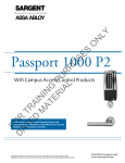
P2
PASSPORT 1000
Mortise Lock
Installation Instructions
A8011E
03/14
Copyright 2014, Sargent Manufacturing Company, an ASSA ABLOY Group company.
All rights reserved. Reproduction in whole or in part without the express written
permission of Sargent Manufacturing Company is prohibited.
Table of Contents
1
2
3
4
5
6
7
1
Warning ....................................................................................2
General Description..................................................................3
Hardware Specifications..........................................................3
Electronic Specifications..........................................................3
Parts Breakdown......................................................................4
Installation Instructions...........................................................6
Operational Check..................................................................17
Warning
Changes or modifications to this unit not expressly approved by the party responsible
for compliance could void the user’s authority to operate the equipment.
FCC
NOTE: This equipment has been tested and found to comply with the limits for a Class B digital device, pursuant to
Part 15 of the FCC Rules. These limits are designed to provide reasonable protection against harmful interference in a
residential installation.
03/31/14
Copyright © 2014, Sargent Manufacturing Company, an ASSA ABLOY Group company. All rights reserved.
Reproductions in whole or in part without express written permission of Sargent Manufacturing Company is prohibited.
This equipment generates, uses, and can radiate radio frequency energy and, if not installed and used in accordance
with the instructions, may cause harmful interference to radio communications. However, there is no guarantee that
interference will not occur in a particular installation. If this equipment does cause harmful interference to radio or
television reception, which can be determined by turning the equipment off and on, the user is encouraged to try to
correct the interference by one or more of the following measures:
•
Reorient or relocate the receiving antenna.
•
Increase the separation between the equipment and receiver.
•
Connect the equipment into an outlet on a circuit different from that to which the receiver is connected.
•
Consult the dealer or an experienced radio/TV technician for help.
Industry Canada:
Statement: The term “IC:” before the radio certification number only signifies that Industry Canada
technical specifications were met.
This Class B digital apparatus meets all requirements of the Canadian Interference Causing Equipment Regulations.
Operation is subject to the following two conditions: (1) this device may not cause harmful interference, and (2) this
device must accept any interference received, including interference that may cause undesired operation.
Cet appareillage numérique de la classe B répond à toutes les exigences de l’interférence canadienne
causant des règlements d’équipement. L’opération est sujette aux deux conditions suivantes: (1) ce
dispositif peut ne pas causer l’interférence nocive, et (2) ce dispositif doit accepter n’importe quelle
interférence reçue, y compris l’interférence qui peut causer l’opération peu désirée.
SARGENT Mfg. Co. Passport 1000 locksets utilizing a door position switch (DPS) are not rated for,
or intended for use in life safety applications.
!
Any retrofit or other field modification to a fire rated opening can potentially impact the fire rating of the opening,
and SARGENT Manufacturing makes no representations or warranties concerning what such impact may be in any
specific situation. When retrofitting any portion of an existing fire rated opening, or specifying and installing a new
fire-rated opening, please consult with a code specialist or local code official (Authority Having Jurisdiction) to ensure
compliance with all applicable codes and ratings.
To avoid possible damage from electrostatic discharge (ESD), some basic precautions should be used when handling
electronic components:
•
Minimize build-up of static by touching and/or maintaining contact with unpainted metal surfaces such as
door hinges, latches, and mounting plates especially when mounting electronic components such as readers
and controllers onto the door.
•
Leave components (reader and controller) protected in their respective anti-static bags until ready
for installation
•
Do not touch pins, leads or solder connections on the circuit boards
1-800-810-WIRE • www.sargentlock.com • A8011E
Passport 1000 P2 Mortise Lock
2
General Description
The SARGENT Passport 1000 P2 Mortise Lock Lock features HID® multiCLASS SE™ technology, offering
simultaneous support for multiple credential formats as well as an easy migration path to higher security
credentials and NFC mobile access.
Designed specifically for the campus market, the SARGENT Passport 1000 P2 WiFi Mortise Lock* provides
customized access control with magnetic swipe and optional contactless reader and/or keypad, as well as
detailed audit capabilities.
•
Using WiFi technology and coupled with third party software, the P2 Mortise lock offers a complete,
integrated access control system.
•
The Passport 1000 P2 operates on six (6) “AA” alkaline batteries and may be used for both indoor and
outdoor applications.
Note: A weather-protective gasket is recommended for outdoor applications.
HID, iCLASS, iCLASS SE, and multiCLASS SE are registered trademarks or trademarks of HID Global in the U.S.
and/or other countries.
* Patent pending
•
Complete lockset with controller
•
Case - 12 gauge heavy duty wrought steel
•
ADA compliant
•
•
Easily retrofits existing Passport 1000 door
preps (mortise)
Outside lever is unlocked through access
control credentials only
•
Cylinder retracts latchbolt (and deadbolt)
•
Latch - Stainless steel
•
•
Optional deadbolt - Stainless steel
Inside lever retracts latch and deadbolt
simultaneously
•
Guardbolt - Stainless steel, non handed
•
•
Handing (RH/RHR/LH/LHR) must be
specified, but is easily field-reversible
without opening the lock case
Lock furnished for 1-3/4” doors.
For other thicknesses, consult factory.
•
UL Listed (3 hr.)
•
Outside lever controlled by any combination
of keypad, magnetic swipe, contactless
reader, or mechanical cylinder
•
Wireless (WiFi 802.11 b/g) online, batteryoperated
High Frequency (13.56 MHz):
•
2,400 users per lock; 10,000 event audit trail
•
HID iCLASS
•
•
HID iCLASS SE (SIO-enabled)
Multiple time zone and holiday access
scheduling
•
HID iCLASS® Seos™
•
•
HID MIFARE® SE
First-In unlock configuration, based on
specified time schedule
•
HID DESfire® EV1 SE
•
Input Power: DC 9V, 1.5A (6 AA alkaline batteries or optional hard-powered)
•
MIFARE Classic
•
Uses existing Magstripe keycards (track 2)
•
DESfire EV1
•
•
FeliCa
Magnetic Stripe Card Coercivity: HiCo (4000
Oersted) or LoCo (300 Oersted)
Copyright © 2014, Sargent Manufacturing Company, an ASSA ABLOY Group company. All rights reserved.
Reproductions in whole or in part without express written permission of Sargent Manufacturing Company is prohibited.
4
Hardware Specifications
Electronic Specifications
•
HID® multiCLASS SE™ technology offers
support for the following credentials:
•
®
®
•
Low Frequency (125 kHz):
•
•
• HID Prox®
Magnetic Stripe
Support for most advanced wireless encryption
and authentication standards.
•
•
NFC-enabled Mobile Phones
For specific security information, please contact
your local ASSA ABLOY Door Security Solutions
sales consultant or call 800-810-WIRE.
1-800-810-WIRE • www.sargentlock.com • A8011E
3
03/31/14
3
Passport 1000 P2 Mortise Lock
5
Parts Breakdown
P2 WiFi Lock with Magnetic Card Swipe With or Without Keypad
4
3
1
2
03/31/14
Copyright © 2014, Sargent Manufacturing Company, an ASSA ABLOY Group company. All rights reserved.
Reproductions in whole or in part without express written permission of Sargent Manufacturing Company is prohibited.
ITEM No.
1
2
3
4
PART No.
DESCRIPTION
52-3583-[finish]
Outside Escutcheon Assemby, mag stripe
52-3582-[finish]
Outside Escutcheon Assemby, mag stripe and Keypad (shown)
52-4244-[finish]
Outside Escutcheon Assemby, Mag Swipe, Keypad, and HID 125 kHz Prox
52-4759-[finish]
Outside Escutcheon Assemby, iCLASS, keypad, mag stripe, Prox, smart card (MIFARE, DESFIRE)
52-4777-[finish]
Outside Escutcheon Assemby, iCLASS, mag stripe, Prox, smart card (MIFARE, DESFIRE)
52-4787-[finish]
Outside Escutcheon Assemby, FeliCa, keypad, mag stripe, Prox
52-4788-[finish]
Outside Escutcheon Assemby, FeliCa, mag stripe, Prox
52-4779
Mounting Plate Assembly
52-5409
WiFi Controller Assembly
52-4796
WiFi Radio Module (not shown)
52-4776-[finish]
Inside Escutcheon Assembly with Privacy Button
Tools Required:
4
1-800-810-WIRE • www.sargentlock.com • A8011E
•
#2 Phillips screwdriver
•
Flat head
•
T20 Torx® driver
•
Security allen wrench
(provided)
Passport 1000 P2 Mortise Lock
Parts Breakdown (Continued)
6
5
4*
3
8
9
10
11
12
13
7
14
17
ITEM
PART No.
DESCRIPTION
1
See catalog
#41 Cylinder (1-1/8” Minimum Length)
2
13-0140
Cylinder Compression Spring
3
See catalog
1KB-1 Cylinder Rosette
4
P2-82276-[finish]*
Lock body with deadbolt & with cylinder
P2-82277-[finish]*
Lock body with deadbolt without cylinder
P2-82278-[finish]*
Lock body without deadbolt with cylinder
P2-82279-[finish]*
Lock body without deadbolt without cylinder
5
77-2592
130 KB Thumb turn for Deadbolt Functions Only
6
See catalog
Inside Lever Handle
7
See catalog
Outside Lever Assembly
8
82-0368
Spindle
9
82-3088
Inside Lever/Knob Adapter Plate Assembly
10
01-1495
#8-32 X 5/8 Machine Screw
11
82-0612
Non Loosening Wave Washer
12
See catalog
Mortise Rose
13
82-0347
Spindle Spring
14
01-1019
#12-24 X 1/2” Machine Screw
15
01-2299
12 X 1-1/4 Wood Screw
16
82-0578
Outside Front Plate (Electrical, Latchbolt & Guardbolt)
82-0579
Outside Front Plate (Electrical, Deadbolt, Latchbolt and Guardbolt)
01-1028
#8-32 X 1/4 Machine Screw
17
Copyright © 2014, Sargent Manufacturing Company, an ASSA ABLOY Group company. All rights reserved.
Reproductions in whole or in part without express written permission of Sargent Manufacturing Company is prohibited.
16
* Patent Pending
1-800-810-WIRE • www.sargentlock.com • A8011E
5
03/31/14
15
Passport 1000 P2 Mortise Lock
Installation Instructions
6
1
Door Preparation
A. Verify Hand and Bevel of Door
Stand on outside of locked door when determining door hand.
Left Hand
Hinges Left.
Open Inward.
“LH”
Left Hand
Reverse Bevel
Hinges Left.
Open Outward.
“LHRB”
Right Hand
Hinges Right.
Open Inward.
“RH”
Right Hand
Reverse Bevel
Hinges Right.
Open Outward.
“RHRB”
B. Door Preparation
Refer to template A7950 for wood and metal doors.
03/31/14
Copyright © 2014, Sargent Manufacturing Company, an ASSA ABLOY Group company. All rights reserved.
Reproductions in whole or in part without express written permission of Sargent Manufacturing Company is prohibited.
Outside of Door
Inside of Door
Inside Mounting Plate
Mounting Holes
Raceway for Power
(optional)
Through Bolt Holes
Raceway for Power
(optional)
Cylinder Hole
Thumb Turn Location
(Deadbolt Functions Only)
Lever Handle Holes
Lever Handle Holes
Mortise
Pocket
(8200)
6
1-800-810-WIRE • www.sargentlock.com • A8011E
Passport 1000 P2 Mortise Lock
2 Prepare Lock Body
A. Reverse Lock Hand (If Required)
1. Position lock body so that red surface of locking piece is visible.
2. Insert blade type screwdriver into locking piece slot to rotate
locking piece.
3. Push locking piece toward the back of the lock
body and rotate the locking piece 180°.
Note: Red indicates locked (outside) side.
Locking piece
Fig. 2A
B. Reverse Latch Hand (If Required)
4. Rotate the latchbolt 180° (Fig. 2B).
Latchbolt
Deadlatch
Locking piece
Fig. 2B
1-800-810-WIRE • www.sargentlock.com • A8011E
7
03/31/14
Copyright © 2014, Sargent Manufacturing Company, an ASSA ABLOY Group company. All rights reserved.
Reproductions in whole or in part without express written permission of Sargent Manufacturing Company is prohibited.
5. Flip deadlatch by hand to match bevel of latchbolt.
Passport 1000 P2 Mortise Lock
3 Install Lock Body
Note: Do not pull the lock into the pocket using the harness alone.
Ensure that the wire harness is not pinched between the lock and the mortise pocket.
1. Feed the wire harness into the mortise pocket and
through inside preparation hole as depicted in Figure 3.
2. Carefully push the lock body into the pocket while
lightly applying tension to the wire harness.
Inside of Door
3. Insert (2) #12-24 screws into the lock body
(Fig. 4) and tighten* with a screw driver.
*Do not fully tighten until cylinder and levers
are installed and properly aligned.
03/31/14
Copyright © 2014, Sargent Manufacturing Company, an ASSA ABLOY Group company. All rights reserved.
Reproductions in whole or in part without express written permission of Sargent Manufacturing Company is prohibited.
Ground
Wire
(2) #12-24
screws
Wire
Harness
Fig. 3
8
1-800-810-WIRE • www.sargentlock.com • A8011E
Passport 1000 P2 Mortise Lock
4 Outside Cylinder Installation
1. Slide the spring and the rosette onto the cylinder.
2. Rotate the cylinder into cylinder hole with fingers.
3. Insert key 75% of the way and utilize the key to rotate the cylinder
into the rest of the cylinder hole.
Note: Do not attempt to tighten all the way.
IMPORTANT: Position cylinder so that the
SARGENT logo is positioned correctly.
4. Verify that orientation of cylinder has the SARGENT logo as depicted
in Fig. 4A.
5. Hand tighten the cylinder clamp screw with Phillips screwdriver to
prevent unscrewing of the cylinder (Fig 4C).
Correct
6. Test cylinder function:
•
Key retracts latchbolt and deadbolt (7976 function).
•
Key retracts latchbolt (7978 function).
•
Cylinder not present for 7977 and 7979 functions.
Incorrect
Fig. 4A
Rosette
Spring
Phillips
Screwdriver
Cylinder
Cylinder
Clamp Screw
Fig. 4B
Fig. 4C
1-800-810-WIRE • www.sargentlock.com • A8011E
9
03/31/14
Copyright © 2014, Sargent Manufacturing Company, an ASSA ABLOY Group company. All rights reserved.
Reproductions in whole or in part without express written permission of Sargent Manufacturing Company is prohibited.
Outside of Door
Passport 1000 P2 Mortise Lock
5 Assemble Outside Trim
1. With outside lever horizontal, insert the mounting posts through outside of door and lock body.
Make certain the lever spindle is properly engaged inside the lock body (Fig 5A).
2. On the inside of the door, insert spindle into square hole of mortise lock (Fig 5B).
3. Slide inside adapter and plate assembly over spindle and secure with (2) 8-32 X 5/8” Phillips
oval head and lock washer machine screws.
Note: Ensure that position of set screw hole on inside adapter is oriented to match location of hole in
inside lever handle.
Inside of Door
Outside of Door
Outside Trim
Ground Wire
03/31/14
Copyright © 2014, Sargent Manufacturing Company, an ASSA ABLOY Group company. All rights reserved.
Reproductions in whole or in part without express written permission of Sargent Manufacturing Company is prohibited.
Wire Harness
(From Lock Body)
Fig. 5A Detail
Set Screw Hole
Spindle
Spindle
Outside Trim
10
Fig. 5A
1-800-810-WIRE • www.sargentlock.com • A8011E
Fig. 5B
Passport 1000 P2 Mortise Lock
6 Install Inside Rose and Inside Lever Assembly
1. Place inside rose flush against door surface and rotate first counter-clockwise to
seat the threads, then clockwise to securely tighten.
2. Slide lever onto spindle until fully seated. Be sure handle is horizontal and
facing the hinge side of the door. Push lever onto spindle so minimum gap
is visible.
3. Tighten the set screw securely with a T20 Torx® driver.
4. Finish securely tightening (2) #12-24 lock body screws.
5. Before closing the door, test that the lever is functional and ensure
smooth operation of the latchbolt.
Rose
#12-24 screws
Spindle
Inside Lever
Set Screw
Fig. 6
1-800-810-WIRE • www.sargentlock.com • A8011E
11
03/31/14
Copyright © 2014, Sargent Manufacturing Company, an ASSA ABLOY Group company. All rights reserved.
Reproductions in whole or in part without express written permission of Sargent Manufacturing Company is prohibited.
Inside of Door
Passport 1000 P2 Mortise Lock
7 Install Thumb Turn
1. Insert thumb turn into preparation hole and engage slot in lock body.
2. Orient mounting plate so screw hole is vertical (aligned with preparation holes).
3. Secure plate with Phillips screw provided.
4. Test thumb turn for function by retracting and projecting the deadbolt
(7976 and 7977 functions only).
Inside of Door
Phillips
screw
Thumb Turn
03/31/14
Copyright © 2014, Sargent Manufacturing Company, an ASSA ABLOY Group company. All rights reserved.
Reproductions in whole or in part without express written permission of Sargent Manufacturing Company is prohibited.
Fig. 7
8 Install Gasket (Optional) and Outside Escutcheon
Note: Gasket is optional, for non-fire rated doors only.
For non-fire rated door applications, a gasket (Part number 52-0782)
may be used as a weather seal between the escutcheon and the
outside door surface.
1. Peel off adhesive backing and attach to outside escutcheon.
Outside of Door
Escutcheon
Gasket
2. Insert the mounting posts through holes as shown.
3. Feed reader cable through side opening (Fig. 8).
Fig. 8
12
1-800-810-WIRE • www.sargentlock.com • A8011E
Passport 1000 P2 Mortise Lock
9 Install Gasket (Optional) and Outside Escutcheon
Note: Gasket is optional, for non-fire rated doors only.
For non-fire rated door applications, a gasket (Part number 52-0782)
may be used as a weather seal between the escutcheon and the
outside door surface.
Escutcheon
Gasket
1. Peel off adhesive backing and attach to outside escutcheon.
2. Insert the mounting posts through holes as shown.
3. Feed reader cable through side opening (Fig. 9).
Fig. 9
10 Mounting Plate Assembly
1. On the inside of the door, position the mounting plate
over the indicated holes.
Cable from lockbody feeds from bottom (Fig. 10A and 10B).
Ground ring should be positioned upright (Fig. 10B).
Mounting Plate
Position ground
ring terminal
upright, then
tighten screw.
Fig. 10B
Lock body cable
Fig. 10A
1-800-810-WIRE • www.sargentlock.com • A8011E
13
03/31/14
Copyright © 2014, Sargent Manufacturing Company, an ASSA ABLOY Group company. All rights reserved.
Reproductions in whole or in part without express written permission of Sargent Manufacturing Company is prohibited.
Mounting plate
2. Insert other three #8-32 x 1-7/8” flat head machine
screws and tighten, fastening the outside escutcheon
to the door (Fig. 10B).
Passport 1000 P2 Mortise Lock
11
Installation of Connectors
CAUTION - Do not touch or allow debris to enter connector contacts.
Reader
(24-pin)
Secure the following connectors to their respective terminals (Fig. 11A, B ):
9-24VDC
Power*
A. Secure the 10-pin lock body assembly connector.
*NOTE: Optional 2-pin external 12-24VDC power connector.
D
Board-to-Board
Connector
Fig. 11A
A
Lock
Body
(10-pin)
Fig. 11B
03/31/14
Copyright © 2014, Sargent Manufacturing Company, an ASSA ABLOY Group company. All rights reserved.
Reproductions in whole or in part without express written permission of Sargent Manufacturing Company is prohibited.
Wire Positioning:
Please follow these steps prior to installing
inside escutcheon to prevent any damage
caused by pinching wires:
B
B. Tuck excess cable into wire hole on inside of door (Fig. 11C).
C. Finish securing mounting plate and reader to door by fully
tightening through-bolts on inside of door.
Tuck excess
cable here
D. Secure the 24-pin card reader connector.
Fig. 11C
14
1-800-810-WIRE • www.sargentlock.com • A8011E
Passport 1000 P2 Mortise Lock
12 Install Inside Module Component Assembly
1. Insert bottom tab of controller into slot on mounting plate (Fig. 12A, B).
2. Looking down from top of controller, ensure proper alignment of
board-to-board connectors (Fig. 12B) while pivoting controller
toward door until two tabs on top snap securely into place on
mounting plate (Fig. 12A).
Board-to-Board
Connectors
Fig. 12B
Fig. 12A
Fig. 12B Detail
Fig. 12A Detail
1-800-810-WIRE • www.sargentlock.com • A8011E
15
03/31/14
Copyright © 2014, Sargent Manufacturing Company, an ASSA ABLOY Group company. All rights reserved.
Reproductions in whole or in part without express written permission of Sargent Manufacturing Company is prohibited.
CAUTION: To avoid possible damage to board-to-board connectors,
care should be taken when securing controller to mounting
plate. If there is resistance when securing, detach controller
to determine cause before re-attaching controller.
Passport 1000 P2 Mortise Lock
13 Install Batteries
Before installing batteries for the first time:
Remove pull tab from its position beneath the coin cell by pulling
on tab in direction of arrows printed on tab (Fig. 13).
a. Place (6) “AA” alkaline batteries in the compartment, being
careful to align polarity properly.
b. After batteries are installed, there is a slight delay; then the LED
will flash amber and the lock motor will cycle.
For battery replacement:
When replacing the (6) “AA” alkaline batteries in the compartment,
please note batteries must be replaced within five (5) minutes to
prevent the internal clock from becoming inaccurate.
Coin Cell
Pull Tab
Fig. 13
Copyright © 2014, Sargent Manufacturing Company, an ASSA ABLOY Group company. All rights reserved.
Reproductions in whole or in part without express written permission of Sargent Manufacturing Company is prohibited.
14 Install Inside Escutcheon
1. Position inside escutcheon as shown (Fig. 14).
Verify that all wires are positioned within the escutcheon
to avoid pinching.
2. Attach escutcheon with (2) #8-32 x 1/2” T-20 Torx pan
head screws.
3. Straighten escutcheon and tighten securely.
DO NOT OVERTIGHTEN.
(2) #8-32 x 1/2”
Torx Screws
03/31/14
Fig. 14
16
1-800-810-WIRE • www.sargentlock.com • A8011E
Passport 1000 P2 Mortise Lock
15 Attach Outside Front Plate
Attach front plate with (2) #8-32 X 1/4” flat head
screws (Fig. 14).
Inside of Door
(2) #8-32 x 1/4”
Flat Head Screws
Fig. 14
Operational Check
7
IMPORTANT: Be sure to test functions prior to closing door.
•
For units with cylinders, the following checks apply:
Insert key into cylinder and rotate:
a. There should be no friction against the lock case or any other
obstructions. If frictions or binding occurs, re-adjust cylinder to
eliminate issues.
b. The key should retract the latch and the key should rotate freely.
c. The key should extend and retract the deadbolt.
•
For units without a keypad, add card using LCT
software and test.
•
For units with a keypad, add pin and card using LCT software and test.
2. LED signaling:
•
After using a valid credential, a green flash followed by three fast amber
flashes indicates a low power condition.
Check the battery voltage.
If the voltage is low, replace the batteries.
•
If the lock loses power, it will flash rapid amber for approximately one
minute. Lock will default to programmed fail safe or fail secure.
3. When you have completed the tests, close the door, ensuring latchbolt and
deadbolt fully extend into strike plate without binding.
Fig. 15
1-800-810-WIRE • www.sargentlock.com • A8011E
17
03/31/14
Copyright © 2014, Sargent Manufacturing Company, an ASSA ABLOY Group company. All rights reserved.
Reproductions in whole or in part without express written permission of Sargent Manufacturing Company is prohibited.
In all cases, perform the following checks:
1. Ensure that inside lever retracts latch (and deadbolt for deadbolt functions).
SARGENT Manufacturing
100 Sargent Drive
New Haven, CT 06511 USA
800-810-WIRE (9473) • www.sargentlock.com
Founded in the early 1800s, SARGENT® is a market leader in locksets, cylinders, door closers, exit devices,
electro-mechanical products and access control systems for new construction, renovation, and replacement applications.
The company’s customer base includes commercial construction, institutional, and industrial markets.
Copyright © 2014, Sargent Manufacturing Company, an ASSA ABLOY Group company. All rights reserved.
Reproduction in whole or in part without the express written permission of Sargent Manufacturing Company is prohibited.
ASSA ABLOY is the global leader in door opening solutions, dedicated to
satisfying end-user needs for security, safety and convenience.
A8011E -03/14