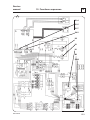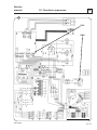
1
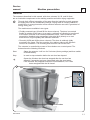
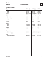
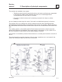
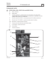
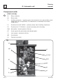
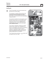
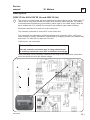
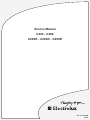
Service Manual
C240 - C260
C240R - C260R - C290R
487 03 29 91/EN
08.28
Service
manual
Overview
Machine presentation
1
Technical data
2
Description of principal components
3
Service
Instruction
Periodic maintenance
11
Function sequences
12
Machine
units and
components
Automatic unit
21
22
23
24
25
26
27
28
Lid and lid lock
29
Motors
30
31
Included
units
and
somponents
32
33
34
35
36
37
38
39
40
41
Drum
487 03 29 91
1
Service
manual
Machine presentation
1
General
The extractors described in this manual, with drum volumes 38, 58 and 88 litres,
are an invaluable complement to the washing machine and other drying equipment.
Through their efficient extraction of the water from the load after a wash program,
the drying time can be considerably reduced. Drying wash in a drying cabinet or
tumble dryer is energy-intensive and an efficient extractor can save a great deal of
energy every year.
1
The machines are available in two types:
• Flexibly-mounted type (38 and 58 litre drum volumes). The drum is mounted
flexibly in relation to the frame. As a result, a minimum of vibration is transferred
to the frame, and this in turn makes installation easier. These extractors can
generally be installed using expanding bolts (size M12) directly on a cast
concrete floor of good quality and sufficient thickness.
• R-model (38,58 and 88 litre drum volumes). The drum is relatively rigidly
mounted in the frame. The floor must be very stable to take up the dynamic
forces from extraction. The mounting bolts must be cast inti the floor.
The extractor is controlled by means of three buttons on a control panel. The
buttons have the following functions:
Start
Starts the extractor. It will run for 5 minutes (factory settings) and then switch
off automatically.
Stop
Is used to stop extraction before the set time has elapsed.
Opens the lid when the drum has stopped after the set time has
elapsed, if extraction has been interrupted using the stop button,
if the extractor has stopped because of load imbalance, or if it has
been energised with the lid closed.
1
Lid
Service door
487 03 29 91
1.1
1
Machine presentation
Service
manual
Safety rules
• The machine must not be operated be children.
• Do not leave children alone or unsupervised in the vicinity of the extractor.
• The machine must not be hosed down with water.
• Installation and servicing are to be performed be authorised personnel only.
• The machine´s lid lock must not be bypassed under any circumstances.
• The extractor must not be connected to a central time-switch which cuts the
power supply to it at a certain time each day. If the power supply is cut
during an extraction cycle the lid cannot be opened. This means that there is
a risk of the lid being forced open.
• If a fault arises, e.g. when the yellow light by the STOP button flashed on
and off, this should be reported to the technician responsible for the machine
as soon as possible. This is important for your own safety and that of other
people.
1.2
487 03 29 91
Service
manual
2
2. Technical data
Technical data
Type
C240 (R)
C260 (R)
C290R
Dimensions:
Width
Depth
Height
515 mm
660 mm
850/910 mm
640 mm
785 mm
870/980 mm
770 mm
910 mm
1050 mm
Weight
Drum
Diameter, base
Diameter, top
Height
Volume
74/85 kg
109/140 kg
190 kg
400 mm
350 mm
340 mm
38 litres
530 mm
450 mm
305 mm
58 litres
630 mm
556 mm
320 mm
88 litres
Capacity
8 kg
12 kg
18 kg
Speed
50Hz
60 Hz
1450 rpm
1740 rpm
1450 rpm
1740 rpm
1450 rpm
1740 rpm
G-factor
50 Hz
60 Hz
440
635
575
830
705
1015
Power output
50 Hz during operation
60 Hz during operation
0,33 kW
0,40 kW
0,45/0,55 kW 0,65 kW
0,55/0,65 kW 0,75 kW
Drain
Hose, inner diameter
Ø 75 mm
Ø 75 mm
487 03 29 91
Ø 75 mm
2.1
Service
manual
3. Description of principal components
3
The machine are available in two types:
• Flexibly-mounted, which means that the drum unit (motor and drum) are suspended
in the frame by rubber straps. Beneath the motor is a counterweight which
counterbalances the drum when it is rotation.
• R- model, in which the drum unit is relatively mounted in the frame on rubber
bushings.
An out of balance switch stops the motor if the load is not distributed properly in the drum.
The machine lid is on a slewing arm, which is swung across the drum opening and then
pressed down towards the drum. A microswitch in the control unit and also a Reed element in
the C240/C240R and C260/C260R models check that the lid is closed before the machine will
start.
Two rotation guards, a microswitch and the Reed element lock the lid so that it cannot be
opened until the drum had stopped. If the power supply is interrupted, e.g. by a power cut, it
will not be possible to open the lid until the power supply is restored.
The machine is controlled by means of three buttons on a control panel located to one side of
the lid.
The circuit board for automatic functions, lid lock, relays, transformer etc. are located in the
control unit. Access is easy once the cover is removed.
1
R-
C240/
C260R
C290R
487 03 29 91
3.1
Service
manual
11. Periodic maintenance
11
The following maintenance routines should be adhered to, to ensure satisfactory and
safe operation, and to prevent service stops.
The service intervals set out here are suitable for machines in normal use, for example
in a communal laundry in an apartment building. The intervals should be halved if the
machines is used intensively, e.g. in a commercial laundry.
Once every two weeks
It is important to check the machine´s functions regularly, in particular the safety
aspects.
Check:
• That the lid cannot be opened when it is extracting
• That it stops extracting when the STOP button is pressed
• That switches and electrical supply cable are undamaged
Once every two years
Check the rubber straps supporting the drum unit, and replace them if necessary. See
section 42 “ The drum and its mountings - replacement of mountings”
487 03 29 91
11.1
Service
manual
12. Functions sequences
12
Functonal diagram for hydro-ectrator
487 03 29 91
12.1
12
12. Functions sequences
Service
manual
General
To facilitate fault-tracing in the electrical system, the description which follows has been
divided into function sequences. At the end of this section there is also a table listing a
number of measurement points.
The following sequences are described here:
• Power supply
• Start of extraction
• Lid opening
• Stop after extraction
• Imbalance during extraction
• Measurement points
Power supply (230V, 50 Hz; 400-415V, 50 Hz; and 440V, 60 Hz)
Machine power supply can be 230, 400, 415 or 440 V 3 AC. An auxiliary transformer is
supplied with two of the line voltage phases and steps down the mains voltage to 24 V
control voltage. The auxiliary transformer is protected by two fuses, one on the primary
side (F1) and one on the secondary side (F2).
1
The auxiliary transformer supplies the circuit board for automatic functions and the other
components in the control circuit with control voltage.
1
R2-R1
12.2
487 03 29 91
Service
manual
12
12. Functions sequences
Power supply (380 V 60 Hz)
Machine power supply can be 380 V 3 AC. An auxiliary tranformer is supplied with two of
the line voltage phases and steps down the mains voltage to 24 V control voltage. The
auxiliay tranformer is protected by two fuses, one on the primary side (F1) and one on
the secondary side (F2).
2
The auxiliary transformer supplies the circuit board for automatic functions and the other
components in the control circuit with control voltage.
2
C290R
R2-R1
Terminal connections (X1)
487 03 29 91
12.3
12
12. Functions sequences
Service
manual
Circuit diagram 489 50 01 77 has been used in describing the function sequence in this
section: This diagram is in principle identical to all the other circuit diagrams since the
control voltage is 24 V AC 50/60 Hz.
Start of extraction
3
The machine starts extraction when the operator presses the START button on the
control panel.
Drive motor M1 is energised via connection X3-X5 (star connection) or X2-X7(delta
connection) when relay K1 operates. For K1 to operate, the following conditions must be
fulfilled:
• The lid´s Reed element R1-R2 must be activated, e.g. the lid closed (this does not
apply to the C290R, which has no Reed element in the lid).
• The mechanical lid switch (SW1) must be activated (lid Closed).
When the lid´s Reed element closes, a signal (GND potential) is obtained at terminal
OUT1 S3 on connection S3. This signal is supplied via the circuit board to terminal
GND2 on connection S6. Terminal OUT2 on S6 will have GND, potential, which
allows the extractor to start.The logic circuit will now supply control voltage to terminal
S1:4, which via an interlock contact on brake relay K2 supplies one side of relay coil
K1. The other side of the relay coil receives voltage from S1:2 via lid switch SW1 and
the motor´s internal thermal protection F3.
When K1 operates, an interlock contact in the control circuit opens to relay K2 (brake
relay), thereby preventing K2 from operating at the same time as K1.
12.4
487 03 29 91
Service
manual
12
12. Functions sequences
3
R1-R2
R1
R2
S3:out 1
S6:out 2
S1:2
S1:4
S1
K2
K1
M1
F3
487 03 29 91
12.5
12
12. Functions sequences
Service
manual
Lid Opening
4
The lid is opened by pressing the
button on the control panel. The
following conditions must be fulfilled before the lid will open:
• The machine power supply must be on
• The drum must be completely at a standstill i.e. rotation guards H1
(S4:2) and SW2 (S1:7) must have sent the opening signal.
The lid lock is released with the aid of the traction magnet Y1.
The control circuit of Y1 takes its voltage from the circuit board, output
S1:6, via rotation guard SW2. When the drum is completely still rotation
guard H1 gives the go-ahead signal for lid opening to the logicsection on
the circuit board (S4:2).
12.6
487 03 29 91
Service
manual
12
12. Functions sequences
4
R1
S1:6
R2
S1:7
S4:2
Y1
H1
SW2
487 03 29 91
12.7
12
12. Functions sequences
Service
manual
Stop after extraction
The machine will stop extracting in the following three cases:
• When the preset extractor time has elapsed (approx. 5 minutes).
• When the operator presses in the STOP button on the control panel.
• When the out of balance switch is activated.
5
The machine´s braking function on the circuit board (output S1:5) is activated after the
control circuit to extraction relay K1 (S1:4) has been broken. The control circuit for the
braking relay K2 is closed (interlock contact in K1 closed), after which K2 operates and
inverts the phase of the drive voltage to motor M1, Which thereby gains braking power.
When K2 operates, an interlock contact in the control circuit opens to relay K1 (extraction
relay) and prevents K1 from operating at the same time as K2.
When the logic circuit detects that the motor has stopped (rotation guard H1 (S4:2) and
SW2 (S1:7) have sent impulses), K2 is de-energised again and the machine is ready for
lid opening.
12.8
487 03 29 91
Service
manual
12
12. Functions sequences
5
R1
R2
S1:4
S1:5
S1:7
S4:2
K2
K1
H1
M1
SW2
487 03 29 91
12.9
12
12. Functions sequences
Service
manual
Imbalance during extraction
6
In the event of imbalance, extraction is halted so that the load can be manually
redistributed.
The sensor arm of the microswitch (SW3) is activated if there is load imbalance, and it
in turn sends a signal to the circuit board (S2:2) for activation of the braking function and
subsequent possibility of lid opening function.
12.10
487 03 29 91
Service
manual
12
12. Functions sequences
6
R1
R2
S2:2
SW3
487 03 29 91
12.11
12
Service
manual
12. Functions sequences
Faults and corrective action required
Faults indecated by flashing yellow light
Fault
Possible cause
Action
1. The extractor will not start. Yellow
light flashing.
Reed element ring in the deck is
defective
Disconnect main power supply to
extractor. Check that the two
connentions of the Reed ring to the
circuit board for automatic functions are
OK. If they are sound, replace the Reed
ring.
2. The extractor has switched to
braking during extraction. The
extractor will not restart.
The Reed in the deck or the microswitch SW1 has developed a defect
during extraction.
Disconnect main power supply to
extractor. Check that the two connections
of the Reed ring to the circuit board for
automatic functions are OK. If they are
sound, replace the Reed ring. Check that
the microswitch SW1 is OK.
3. The yellow light starts flashing upon
braking. The brake switches off and
the extractor remains locked.
The Hall element of the is
defective.
Disconnect main power supply to
extractor. Check the 3-pole connection
to the circuit board. If this is sound,
replace the motor.
4. No signal comes from the machine´s
mechanical rotation guard upon
braking (at the point where the drum
begins to rotate anticlockwise).
• The microswicth of the rotation
guard has stuck in its rest position.
Disconnect main power supply to
extractor. Remove cover of automatic
control unit. Open extractor lid manually
by pressing the yoke of the traction
magnet upwards.
The drum rotates anticlockwise for
approx. 1 1/2 minutes and then
braking switches off and the yellow
light starts to flash (time varies
according to machine type, load and
frequency).
• The microswitch of the rotation
guard has moved from its position.
• The motor brake pads are worn
The extractor´s lid remains locked.
Connect a multimeter between
connections 502 AC and 503 AC (S1:2-7)
Turn the drum anticlockwise by
hand. If the rotation guard is sound the
meter should react.
If the meter does not react - check the
contacts in the 4-pole connection block
X8/X9) and the 3-pole connection block
X10/X11.
If contact is correct from X10 to S1
replace the motor.
5. The signal from the machine´s
mechanical rotation guard is
constantly active. Braking switches
off immediately. The extractor lid
remains locked.
The yellow light flashing after
approx. 1 1/2 minutes.
The rotation guard microswitch has
burnt out in the active position.
Disconnect main power supply to
extractor. Remove cover of control unit
Open extractor lid manually by pressing
the yoke of the traction magnet
upwards.
Connect a multimeter between
connections 502 AC and 503 AC (S1:2-7)
If the rotation guard is sound the meter
should react.
if the meter does not react - check wires
and connection blocks X8/X9 and
X10/X11 for short circuits.
If there is no short circuit in the control
unit, the microswitch in the
motor is faultyreplace the motor.
12.12
487 03 29 91
Service
manual
12
12. Functions sequences
Fault
Possible cause
Action
6. Extraction interrupted and lid
remains locked. After the full
extraction time has elapsed and
when the drum is at a standstill the
yellow light starts flashing.
The motor´s internal thermal protection Disconnect main power supply to
has cut out the motor during
extractor. Remove cover of control unit.
extraction.
open extractor lid manually by pressing
the yoke of the traction magnet
upwards.
Connect a multimeter between S1:2
(cable 502AC) and SW1:C (cable 512L)
If the thermal protection is sound the
meter will react.
If the meter does not react - wait for
about 1 hour and check with meter
again (if a sound thermal protection
device trips, it will return to normal
automatically).
If the fault remains - replace the motor.
Faults indicated by means other than flashing yellow light
Fault
Possible cause
Action
7. The machine will not start when the
START button is pressed (even
when the lid has been opened and
closed again).
Fault, in control unit, between S2:1
and microswitch SW1.
Disconnect main power supply to
extractor. Remove automatic control
unit cover.
Use a multimeter to check (with the
extractor lid OPEN) the connection
betweeen S2:1 (cable 508L) and SW1:C
(cable 512L).
The light by the OPEN LID button
keeps falshing.
Change falulty cable or microswitch S1.
8. The machine will not start, but the
START light comes on after the
START button is pressed. The lid of
the extractor remains locked.
After opening the lid manually by
pushing on the yoke of the traction
magnet, the yellow light starts to
flash.
487 03 29 91
Fault, in control unit, between the coil
of K2 and microswitch SW1:C.
Disconnect main power supply to
extractor. Remove control unit cover.
Use a multimeter to check (with the
extractor lid CLOSED) the connection
between SW1:C (cable 512L) and the coil
of K2 (CABLE 511LB).
Change faulty cable or microswitch SW1.
12.13
12
Service
manual
12. Functions sequences
Measurement points
A number of measurement points are shown in the adjacent diagram. The table below
shows what each measurement is for, where to measure and the value which you should
obtain.
The measurements described below should be made with extractor in inactive state, i.e. with
the drum not rotating.
Special care must be taken at the measurement points for the edge connections to the
curcuit bourd for automatic functions. The “measurement covers” for connections must be
opened with no power supply present (Main switch - Off).
Edge connection X16 supplies the primary voltages to the auxilliary transformer, when
measuring S3 and S6 of the Hall element, small thin measuring clips for digital meters must
be used.
Pos. signal
Measurement
point
Correct value
A
X1:L3,L2 and L1
115V, 200V,
208-240V,
230V, 380V, 400V,
415V or 440V
B Primary voltage
X16: 1-3
As above
C
Secondary voltage
from transformer.
X17:1-2
24V AC
D
Power supply, circuit board
Power supply, circuit board
S1: 1-2
S1: 2-3
24V AC
24V AC
E
Hall element in motor,
power supply.
S4: 3-1
5V AC
output**
S4: 2-1
Incoming mains voltage.
to aux. transformer.
5 V DC
1 rev
0 V DC
F*Reed sensor 1 in lid
S3: 1 GND1 - 2 out 1
Open lid ∞ Ω
Closed lid 0 Ω
Reed sensor 2 in lid
S6: 1 GND2 - 2 out 2
Open lid ∞ Ω
Closed lid 0 Ω
F*Except C290R
** 0 V DC cannot be measured with an ordinary digital meter during operation.
This potential can be checked with the lid open and by slowly turning the drum clockwise
by hand.
12.14
487 03 29 91
Service
manual
12
12. Functions sequences
R1
F
R2
E
D
C
B
A
487 03 29 91
12.15
Service
manual
21
21. Automatic unit
Component units
1
(230V 50 Hz; 400- 415V 50 Hz and 440V 60 Hz)
K1
Relay, extraction
K2
Relay, brake
T1
Auxiliary transformer - supplies power to the electronics unit, and provides
control voltage 24 V AC to components. The transformer is switchable for mains
voltages: 230 V, 400 V, 415 V and 440 V.
F1
Precision fuse M 0.2 A/500 V - protects primary side of auxiliary transformer.
F2
Precision fuse T 2.5 A/500 V - protects secondary side of auxiliary.
SW1
Microswitch - detects position of lid lock.
CP
Control panel with push-button and indicator lights.
Y1
Lock magnet - operate the lid lock.
MP
Circuit board.
X1
Terminal connection.
1
CP
MP
Y1
Lid lock
F2
SW1
K2
K1
T1
X1
F1
487 03 29 91
21.1
21
Service
manual
21. Automatic unit
Component units
(380 V, 60 Hz)
1
K1
Relay, extraction
K2
Relay, brake
T1
Auxiliary transformer - supplies power to the electronics unit, and provides control
voltage 24 V AC to components. The transformer is connected for the mains
voltage 380 V.
F1
Precision fuse M 0.2 A/500 V - protects primary side of auxiliary transformer.
F2
Precision fuse T 2.5 A/500 V - protects secondary side of auxiliary.
SW1
Microswitch - detects position of lid lock.
CP
Control panel with push-button and indicator lights.
Y1
Lock magnet - operate the lid lock.
MP
Circuit board.
X1
Terminal connection.
1
CP
MP
Y1
Lid lock
F2
SW1
K2
K1
T1
X1
F1
21.2
487 03 29 91
Service
manual
29
29. Lid and lid lock
Lid lock
1
The lid is mounted on an arm and closes onto
the deck of the outer casing.
1
CP
Arm
The extractor is closed by first moving the lid
over the drum and then pressing the arm
downwards. The arm activates a mechanical
lid lock which prevents the lid from being opened
during extraction.
Traction
magnet
To prevent the machine from being able to start
with the lid open there is a microswitch which
detects when the lid lock is engaged. Reed
elements in the lid (on the C240/C240R and
C260/C260R) sense when the lid is pressed
down towards the deck.
The lid lock is opened by activating a traction
magnet which releases the mechanical lock.
For it to be possible to open the lid, the machine
needs to be supplied with power and the
machine´s mechanical rotation guard and the
motor´s Hall element need to have given the
opening signal (drum not rotating).
The lid opened by pressing the
moving the arm to one side.
487 03 29 91
Lid
lock
Micro Switch
SW1
button and
29.1
29
29. Lid and lid lock
Service
manual
Reed element C240, C240R, C260 and C260R
General
The function of the Reed element is to check that the lid is properly closed before
extraction can start.
A complete Reed ring consists of two Reed elements, set the ring itself, beneath the
deck. The cable from the Reed ring is routed out through the edge of the deck via the
control box down to the automatic control unit. The lid is adjusted so that the machine
will stop if the lid is moved upwards or sideways by force from inside or outside the
machine during extraction. Once the extractor has stopped it can be restarted provided
that the lid is properly closed.
Instructions for repair
If the lid is too sensitive during extraction the machine will stop. This may be caused by
a slight lateral movement of the lid. The cause of the fault may be:
• The round rubber dampers are missing or are very worn. Check the dampers in the
control unit. If they are missing or worn the lateral movement will be too great.
• The lid is not centred over the opening. The lid is attached to the arm with a bolt and
locked with a rivet. Check these fastenings.
• The lid is too high. Check the position of the lid when it is opened and moved
sideways. The lid should be as close as possible to the deck. If the clearance is too
great, adjust at the nuts which hold the automatic control unit in place.
• The Reed element is defective. Check according to section 12 “ Function sequencesmeasurement points”
To replace a Reed ring
• Remove the two cable connections on the curcuit board for automatic functions.
• Remove nut and washer (C260 and C260R - 2 of these) securing the Reed/Hall ring
(use a socket wrench)
• Pull the cables out through the hole in the deck.
• Remove the Reed/Hall ring from the deck.
• Install a new Reed ring.
29.2
487 03 29 91
Service
manual
30. Motors
30
Description
(230V 50 Hz; 400-415V 50 Hz and 440V 60 Hz)
The motor is mounted under the drum and drives the drum directly on its output shaft. To
reduce motor noise and vibration the entire drum unit has rubber dampers. On flexiblymounted models this damping is provided by either eight or ten rubber straps, while the
drum models this of R- models is mounted on two relatively rigid rubber bushings.
1
Electrical connection is to block X1 in the control unit.
The extractor connection is to block X1 in the control unit.
The extractors are prepared for switching between star connection (400 - 415V) and
delta connection (230V). Switchover is performed by changing a cable set between relay
and motor. For 440V 60 Hz, cable set A is used.
Cable set A = star connection
Please note!
When the extractor connection type is being switched over,
the auxilliary transformer must also be switched accordingly.
1
When switching over the auxiliary transformer the strap on the transformer connection
block should be moved to the desired voltage.
A
487 03 29 91
B
30.1
30
30. Motors
Service
manual
Description
(380 V, 60 Hz)
The motor is mounted under the drum and drives the drum directly on its output shaft. To
reduce motor noise and vibration the entire drum unit has rubber dampers. On flexiblymounted models this damping is provided by either eight or ten rubber straps, while the
drum unit of R-models is mounted on two relative rigid rubber bushings.
2
Electrical connection is to block X1 in the automatic control unit.
The extractors are connected with cable set A between relay and motor.
2
A
30.2
487 03 29 91
Service
manual
30. Motors
30
Fault-tracing
Motor does not run at all.
• Check the power supply to the motor. Check the motor´s quick connector.
• Check the motor windings with an ohmmeter for short-circuit or failure.
• Check that the motor shaft can be turned. If it can´t, the probable cause
is bearing failure. Replace the motor.
• If, right after stopping, the motor feels abnormally hot, its thermal protection has
probable tripped. Investigate the cause of the overloading. Check that motor and drum
rotate easily.
The motor protection resets automatically when the motor has cooled, after about 30
minutes. Start the machine and listen for any untoward noise.
If the motor protection trips repeatedly, it may be because of short-circuiting. Bearing
failure in the motor may be the cause.
Motor runs slow
The motor is probably operating on only two phases.
• Check that the motor´s power supply is correct.
• Remove the quick connector and use a meter to check the motor windings for failure or
short-circuiting.
Motor is very noisy or seizes
• Bearing failure, replace motor
487 03 29 91
30.3
Service
manual
42
42. Drum
Description
1
These are two methods of mounting the drum
unit in the frame: one for the flexibly-mounted
type, the other for R-model.
• In the flexibly-mounted models (C240 and
C260) the drum unit is suspended from
rubber straps: 8 or 10 according to type.
In these models the mounting cannot
be adjusted, instead the rubber replacement
is needed, then all the straps must be
replaced where necessary. If replacement is
needed, then all the straps should be
replaced with new ones at the same time, to
avoid having to replace others only a short
time later because of uneven strap elestictity.
• In R-models (C240R, C260R and C290R) the
drum unit is relatively rigidly mounted in the
frame with the aid of two rubber bushing.
2
Instructions for repair
Flexibly-mounted models (C240 and
C260)
Check the rubber straps on which the motor is
mounted, and replace where necessary.
Procedure:
• Remove the two service covers.
1
• Lift the motor, holding it under the
counterweight, until the drum reaches the
inside of the top deck.
2
• Prop it from beneath to keep it in raised
position.
3
• Replaced the rubber straps, one at a time,
through the service openings.
3
• Lower the motor. Check that all rubber
straps are positioned correctly.
487 03 29 91
42.1
42
Service
manual
42. Drum
R-models (C240R, C260R and C290R)
5
Checking and adjusting the rigidty of the drum
mounting.
The rigidity of the drum mounting is adjusted by
means of the nuts above the bushing:
three nuts or four according to model.
20-30 mm
Check:
• That the drum is not too loosely restrained.
5
6
Press hard on the drum edge. It should not be
possible to press the drum in more than
20-30 mm. If the mounting is too loose, tighten the
three or four nuts above the bushing.
6
• That the drum is centret, correct this by adjusting
one or more of the nuts on top of the bushing.
7
Look straight down at the extrator drum from above
and compare the drum edge with the opening in the
casing. If the drum is not centred, correct this by
adjusting one or more of the nuts on top of the
bushing.
If any of the nuts should reach the end of its thread
when adjusted, the rubber bushings must be
replaced, see under heading “To replace rubber
bushings”.
7
Please note!
On the C260R and C290R a loose nut can
cause noise. The spring washers under the
nuts increase the latitude of movement.
A
B
A=B
To replace rubber bushing.
• Remove the drain hose.
• Remove the cover over the control unit.
Disconnect the cables from the control unit to the
motor, imbalance switch and outer casing.
- Disconnect the 6-, 3- and 2-pole connectors.
8
- Disconnect the 3-pole edge connector on the
circuit board for automatic functions.
- Disconnect the two yellow/green earth connectons
in the automatic control unit.
- Pull the freed cables down through the conduit
between control unit and outer casing so that they
are clear of the extractor´s outer casing.
8
42.2
• Remove the cap nut securing drum to motor
shaft. Remove drum. Use a special puller (see
figure).
487 03 29 91
Service
manual
• Remove the bolts around base of outer casing.
Lift outer casing and control unit straight
upwards.
9
42
42. Drum
9
• Remove the three or four nuts securing the
bushing. Lift the motor straight upwards.
• Replace the two rubber bushings.
When you replace the upper bushing, do not
remove the supporting journal from the motor. It
can be difficult to adjust when it is put back.
10
Instead, remove the old bushing by cutting it off.
Make a cut in the new bushing as illustrated and
put it in place on the supporting journal. The
vibration from the extractor causes the surfaces
of the cut to vulcanise together after it has been
in use a while.
10
• C240R
11
- Position supporting journal in recess in base
plate and loosely tighten the three nuts above
the bushing.
• C260R, C290R
12
11
- Position supporting journal in frame. Make sure
that the pins on both supporting journal and
frame are corrected positioned in the
corresponding holes of the lower rubber
bushing.
15mm
- Tighten the outer nuts loosely at the top of the
bushing. Use the spring washers under the
nuts.
• Reinstall the outer casing and the cables to the
automatic control unit.
12
• Check the drum and complete the adjustment
of the four nuts according to the instructions
under the heading “checking and adjusting the
rigidity of the drum mounting.
487 03 29 91
42.3
www.electrolux.com/laundrysystems
Share more of our thinking at www.electrolux.com