1
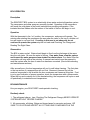
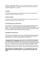
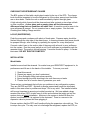
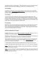
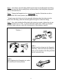
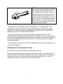
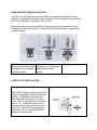
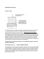
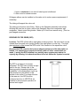
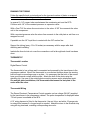
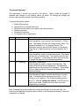
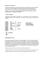
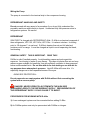
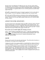
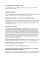
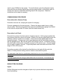
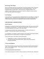
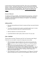
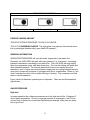
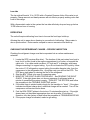
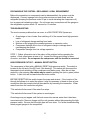
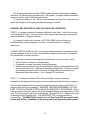
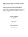
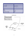
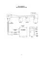
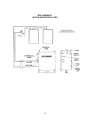
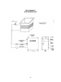
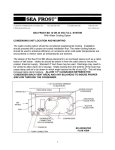
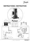
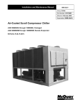
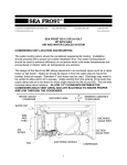
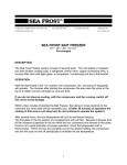
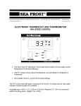
148 OLD CONCORD TURNPIKE BARRINGTON, NH 03825 USA
TEL (603) 868-5720
FAX (603) 868-1040
E-Mail:[email protected]
1-800-435-6708
www.seafrost.com
SEA FROST BAIT FREEZER
BF4 110-VOLT
OPERATION & INSTALLATION
INSTRUCTIONS
SEA FROST
148 OLD CONCORD TURNPIKE
BARRINGTON, NH 03825
U.S.A.
(603) 868-5720
SeaFrost is a registered trademark of C.F. Horton & Co., Inc
Aspects of the SEA FROST design are covered by
US Patent # 4,356,708
Revised 04/2011
Copyright © 2011 by C.F. Horton & Co., Inc.
BF4 OPERATION
Description
The SEAFROST BF4 system is an electrically driven water-cooled refrigeration system.
The compressor and water pump are remotely located. Operation of the compressor
will freeze the cold plates in the boat's insulated box providing refrigeration. If the
insulated box has hidden coils the surface of the inside of the box will begin to cool.
Operation
With the thermostat in the “on” position, the compressor, and pump will operate. Ten
minutes after starting the compressor the area near the valve or the top of a hidden coil
box will begin to cool and frost. If cooling in this area is not observed, do not
continue to operate the system stop the unit and read Checking The Charge and
Reading The Sight Glass.
Observation
The BF4 is water-cooled. Water should begin to flow from the discharge at the same
time the unit starts. Be sure the water is flowing. If no water flows, stop the system
and inspect the water pump and sea strainer for obstructions. If no water flows the
compressor will stop after a few minutes. A manual reset switch must be pressed to
reset the system after the loss of water flow has been corrected. (See trouble shooting
and maintenance sections.)
After several hours, the box temperature will cool to well below freezing. The first plate
or the top section of a wrapped box will cool first. Because it freezes first, all the
moisture suspended in the air within the box condenses and freezes at this plate. Frost
is not a good indication of proper operation; check the temperature with a thermometer.
When the box and contents cool to the desired setting, the compressor will cycle on and
off periodically to maintain the set temperature.
BF4 MAINTENANCE
Like your engine, your SEA FROST needs periodic checking.
Routinely check:
1. The refrigerant charge. (see: Checking The Refrigerant Charge) NEVER OPERATE
SYSTEM WITHOUT PROPER CHARGE.
2. All components, all tubing, fittings and hose clamps for corrosion and wear. BE
SURE TO LOCATE AND INSPECT ALL FITTINGS AND COMPONENTS IN THE
2
SYSTEM. KNOW THE LOCATION OF ALL CONNECTION POINTS. Spray with a
rust inhibitor REGULARLY. Corrosion unchecked in the marine environment will
severely reduce the life of your system.
CLEANING
The Stainless plates should be cleaned with fresh water and soap. Keep salt water
away from the plates and exposed connectors.
WATER STRAINER
The water pump is protected from damage and blockage by a seawater strainer. This
strainer must be inspected and cleaned routinely.
ROUTINE SERVICE AND INSPECTION
We recommend sea strainer inspection before leaving the boat unattended dockside
with the unit on. A visual inspection may be adequate depending on the type of
strainer. To clean most types of strainers, close the seacock, open the strainer, remove
the screen or basket, clean, reassemble and open the seacock. Operate the system
and check for water flow and leaks around the strainer opening.
PUMP IMPELLER INSPECTION
The LC2 pump recommended for this system is a sealed liquid cooled magnetic drive
centrifugal pump. The impeller may be inspected for obstructions and wear by first
closing the seacock. Drain the pump housing by removing a hose.
BE SURE THE PUMP HOUSING IS ABSOLUTELY DRY BEFORE DISASSEMBLY.
It is IMPORTANT that NO WATER flows between the plastic housing and the pump
body. The screws that hold the cover also seal the housing. Water behind the housing
will ruin the motor bearings. Remove the screws holding the inlet fitting plate (larger
hose size). The impeller may be removed with its ceramic seal and thrust washer.
Reassemble in the reverse order. Observe the "O" ring that seals the housing cover
plate. Make sure they are in good condition. Open the seacock and Inspect for leaks.
NEVER OPERATE THE PUMP WHILE DRY. IF IT IS SUSPECTED THAT THIS
CONDITION HAS OCCURRED, INSPECT THE IMPELLER AND HOUSING FOR
WEAR.
3
CHECKING THE REFRIGERANT CHARGE
The BF4 system is fitted with a sight glass located in the top of the RFD. The charge
level should be inspected to be sure refrigerant is of the proper amount and that there
are no slow leaks. Switch the unit on and immediately inspect the sight glass.
A high velocity white foam should be observed and after a minute or two show a black
or clear condition. A clear glass and an empty glass will look the same the
difference being that one condition will make cold. A transition must be seen to be
sure refrigerant is present. Do not operate a low or empty system. See the Leak
Checking and Adding Charge sections.
LAY-UP (WINTERIZING)
Flush the pump and condenser with plenty of fresh water. Pressure water should be
flushed through the inlet side of the water pump. In freezing climates Anti-freeze should
be pumped through, after flushing, by operating the system for a very brief period.
Connect a short hose to the suction side of the pump with a funnel to pour antifreeze
into the system. Run the pump (switch on unit) until antifreeze is pumped through the
seawater circuit. The pump is not self-priming. It must be flooded to pump. It is water
lubricated. DO NOT RUN THE PUMP DRY.
INSTALLATION
Work Habits
Installer's care should be stressed. No matter how good SEAFROST equipment is, its
performance and life are in the hands of the installer. To insure your work:
1.
2.
3.
4.
5.
Read this manual.
Reread any aspect you don't understand.
Follow Swagelok fitting instructions carefully.
Spend enough time leak checking to be sure there are no leaks.
Thanks from all of us who have to guarantee your work.
There are two contaminants that will give you problems in any refrigeration system.
They are WATER and DIRT. Moisture is always present and cannot be eliminated,
water in this case refers to puddles and drops. Dirt is any solid. The installer's habits
will be most important in ensuring a trouble-free start-up. We have added a large
receiver filter dryer (RFD) to take care of all dirt and moisture that might get into the
system during a careful installation. Moisture in the system is boiled off when the
system is evacuated, or it is captured in the desiccant. There is a screen in the
expansion valve to prevent dirt from plugging it.
Excess moisture that the RFD can't handle will plug the expansion valve with ice. This
ice stops the cycle. The only cure is to discharge the refrigerant, replace the RFD, re-
4
evacuate the system, and recharge it. This remedy takes time and is somewhat costly.
Keep the system clean when installing it to save time for something more fun.
Tube Handling
Installation is quite simple. Any routing of the tube must be done with the tube either
taped or capped. Cap both tube ends after each cut. Work with only one line at a time,
and only uncap one end at a time.
Tube Cutting
Use only a tube cutter; hacksawing or any other method will introduce chips to the
system and also distort the tube, making connections difficult and leak-prone. A small
miniature cutter is essential for this work. CUT SLOWLY to avoid a ridge on the inside
of the tube. We do not recommend reaming or dressing the cut, as it is very easy to get
copper chips in the system, which may cause trouble.
Tube Bending
Make all but the long sweep bends with a spring bender; one kink and the line must be
rerun. Don't add any more fittings than are absolutely necessary. Route all lines in
such a way that they are most direct but out of the way. Again, keep everything sealed
until you are ready to make that connection.
NOTES ON SWAGELOK FITTINGS
Swagelok fittings come to you completely assembled, finger tight. (Pieces a, b, and c in
Drawing #1 are already together). They are ready for immediate use.
Disassembly before use can result in dirt and foreign material getting into the fitting and
causing leaks. If disassembly is necessary, reassemble per drawing.
This is double ferrule system. The most serious installation problem encountered with
SEA FROST is the incorrect assembly of these fittings. Be absolutely sure that you
assemble all fittings as in Drawing #1.
To ease assembly slacken the fitting nut slightly before pushing onto the tube, then
retighten with fingers before tightening with a wrench. (This is to avoid cross threading.)
Step 1. Always leave two inches of straight, undistorted tubing leading to all Swagelok
fittings to allow proper connection.
Step 2. Prior to inserting 3/8" tubing into Swagelok tube fitting, make a pencil mark 3/4"
from end of tube as a guide. Prior to inserting 1/4" tubing, make a pencil mark 5/8" from
the end of the tube as a guide.
5
Step 3. Insert clean, smooth tubing with the pencil mark into the Swagelok tube fitting.
You can be sure the tube is resting firmly on the shoulder of the fitting when the pencil
mark is flush with the nut.
Step 4. Tighten the Swagelok nut to a wrench snug* position. Scribe the nut with a
pencil at the 6:00 o'clock position (see drawing, step # 2).
* Wrench snug is the first point in the assembly tightening when the tube cannot be
pulled from the fitting, (when the ferrules tighten enough to contact the tubing).
Step 5. Now, while holding the fitting body with a back-up wrench, tighten the nut oneand-one-quarter turns (1+1/4). To do so watch the scribe mark, make one complete
revolution, and continue to the 9:00 o'clock position. (See drawing, step #3).
Drawing 1
STEP 1
Simply insert the tubing into the Swagelok
tube fitting. Make sure that the tubing rest
firmly on the shoulder of the fitting and that
the nut is wrench snug.
STEP 2
Before tightening the Swagelok nut, scribe
the nut at the six o’clock position.
6
STEP 3
Now, while holding the fitting body steady
with a backup wrench, tighten the nut 1 ¼
turns. Watch the scribe mark, make one
complete revolution and continue to the 9
o’clock position. By scribing the nut at 6
o’clock position as it appears to you, there
will be no doubt as to the starting position.
When tightened 1 ¼ turns to the 9 o’clock
position you can easily see that the fitting
has been properly installed.
* SWAGELOK FITTINGS ARE TO BE TIGHTENED TO A TORQUE SPEC, NOT
INFINITE TIGHTNESS. BE SURE YOUR STARTING POINT IS WRENCH SNUG.
(SEE STEP 4 IN THE SWAGELOK ASSEMBLY INSTRUCTIONS.) A DISTORTED
TUBE MIGHT GIVE A FALSE STARTING POINT.
* Swagelok fittings have a built-in spring interaction between the ferrules. This
compensates for temperature changes and allows the fittings to be reconnected many
times. As the fitting is tightened, a burnishing occurs between the body of the fitting and
the ferrules and between the ferrules and the tube. This action provides the tightest
connection available.
* When making all connections, USE TWO WRENCHES. Don't allow the fittings to turn
or twist when tightening.
RECONNECTING PRE-SWAGED FITTINGS
Connections can be disconnected and retightened many times.
When reconnecting, insert the tubing with pre-swaged ferrules into the fitting until the
front ferrule seats in the fitting. Tighten the nut by hand. Tighten the nut one-quarter of
a turn with a wrench (or to original one-and-one-quarter tight position). Then snug
slightly with the wrench. No more than an additional 1/8 turn.
7
EVAPORATOR PLATE INSTALLATION
The Sea Frost BF plates mount with a Wellnut expandable neoprene blind hole
fastener. A template or the plate itself should be used to locate the mounting holes.
Drill a 3/16" pilot hole. Increase this hole to 3/8".
Mount the plates on opposite walls for a freezer and as high as possible to take
advantage of thermal convection. Install the plates with the Wellnut, spacers and
screws provided.
1. Place Well-nut insert all
the way into Pre-drilled hole
until flange is firmly against
mounting surface.
2. Pass Machine screw
through part to be fastened
and the white spacer
washer.
LARGE PLATE INSTALLATION
These are ½ diameter Wellnuts.
SEA FROST holdover plates mount with a
"Wellnut" expandable neoprene blind hole
fastener. A template or the part itself
should be used to locate the mounting
holes. Drill 1/4" pilot holes then increase
them to 1/2". Install the screw into the
mounting tab then screw the mount onto
the screw. Install the plate pushing the
rubber mounts into the predrilled holes.
Tighten the screws firmly.
8
3. Tighten until snug.
EXPANSION VALVE (CPV)
Installers Set up
The constant pressure valve sets the refrigerant boiling point. Charge amount should
not change the pressure reading. The pressure setting will indicate the minimum
temperature that the freezer system can obtain. It has been pre set at our factory.
Observing the low side pressure with gauges, note that the pressure is constant at 12 to
15 psi depending on the valve setting. If adjustment is needed, set the valve pressure
at the lowest possible pressure setting that will cool the box. The plate temperature will
always be at least 5 to 10 degrees colder than the box. Problems will occur when the
pressure is high and the thermostat is set low; the thermostat will never be satisfied.
The compressor will never stop. Refer to a pressure temperature chart for R-404a to be
sure the plate can reach the thermostat cutout temperature.
The plastic cap is an important moisture seal. Immediately recap the valve after
making an adjustment.
VALVE UNIT (Cast TXV) ……USED ON SOME SYSTEMS
For appearance and convenience of installation, the valve unit (V/U) may mount outside
the insulated box. The valve will attract moisture and drip if it is not well insulated with
the valve blanket and additional insulation. Insulate the valve after installation and leak
checking. In certain applications it may be necessary and easier to mount the valve
inside the cabinet. Refer to schematic drawings when connecting more than one plate.
Before cutting the tubing:
9
1. Leave a minimum of one inch of tube beyond a bulkhead.
2. Allow room for wrench access.
90-degree elbows can be installed on the valve unit to reduce space requirements if
necessary.
The tubing will support the valve unit.
The tubing must bottom in the fitting. Refer to the Swagelok assembly instructions.
Working with one line at a time, remove the Swagelok caps from compressor and
condenser. Attach union fitting bodies. Make up 1/4 turn from wrench snug. (This is a
pre-Swaged connection.
RECEIVER FILTER DRIER (RFD)
Location: The RFD is fitted with a sight glass in the top portion. Be sure that it can be
viewed when mounted in an upright position (the sight glass is on the top). The sight
glass window is offset toward the RFD outlet. Out connects to the expansion valve.
Because the RFD contains desiccant to absorb moisture and the absorption is
limited, it is important to unpack and install it after all other connections are
made. Leaving the RFD installed on a partially open system may reduce its
capacity by allowing it to absorb moisture in free air before the system is sealed.
The RFD is a reservoir for excess
refrigerant. The RFD also contains a sight
glass in the top. (Please refer to the
planning section regarding location and
"readability" of the sight glass) A pick-up
tube extends from the bottom of the
canister to the outlet. For proper function
of the reservoir, the RFD must be
positioned as close to VERTICAL as
possible to ensure proper operation at
various heel angles.
10
RUNNING THE TUBING
Follow the specific hook up instructions for the type and number of plates or wrapped
box and the valve style designated for your system.
In general: A 1/4" copper tube runs between the condensing unit and the RFD.
Continue with 1/4" to the constant pressure or expansion valve.
With a Cast TXV the return line must return to the valve. A 3/8" line connects the valve
unit to the compressor.
With a constant pressure valve the return line connects to the cold plate or exit line on a
wrapped box coil.
If possible run the 1/4" liquid line in contact with the 3/8" suction line.
Support the tubing (every 12 to 18 inches) as necessary with tie wraps after leak
checking and insulating.
Insulate the lines but do not cover the connections until a through leak check has been
done.
THERMOSTAT
Thermostat Location
Digital Ranco Control
The thermostat is low voltage and is connected and powered by the transformer in the
compressor cabinet. Mount the thermostat in a convenient location where the sensing
bulb will reach a mounting screw on a plate. It is necessary that the bulb of the sensor
have good thermal contact with the plate. Attach the bulb to the plate using the
stainless clip. Use one of the existing plate mounting screws as an attachment point.
On multiple plate installations, the thermostat must sense the last plate in the
series after the valve.
Thermostat Wiring
The Ranco Electronic Temperature Control operates on low voltage (24VAC) supplied
by the transformer in the compressor cabinet. The probe temperature is displayed when
110-volt power is available at the BF4.
A 15’ wiring harness is fitted to the thermostat. Use red, blue, and white 16-gauge wire
to extend this harness if a longer length is needed. Attach the wires to the terminal strip
using #8 ring terminals, matching corresponding wire color.
11
Thermostat Operation
The thermostat is pre-set and locked at the factory. When locked the keypad is
disabled and changes to the settings cannot be made. To change the settings the
lockout switch must be placed in the unlock position.
To access the lockout switch:
1.
2.
3.
4.
5.
6.
Switch off the power.
Remove the four screws and cover.
Slide the lockout switch to the right to the unlock position.
Replace the cover.
Re-power the system.
To program refer to table below.
Step
1
Display
F or C
2
S1 (blinking)
3
DIF 1 (blinking)
4
C1 / H1
Description
Fahrenheit or Celsius Scale
Press the set key once to access the Fahrenheit / Celsius
scale. The display will show the current status, either F for
degrees Fahrenheit or C for degrees Celsius. The
thermostat has been pre-set at the factory for Fahrenheit.
Press the up or down arrow key to choose between the F
and C.
Setpoint Temperature
Press the set key again to access the setpoint. The display
will show the current set point. The setpoint has been preset to 0 degrees F. Press either the up or down arrow key
to change the setpoint to the desired temperature.
Differential Temperature
Press the set key again to access the differential. The
display will show the current differential. The differential
temperature has been pre-set at 5 degrees F. Press either
the up or down arrow key to increase or decrease the
differential setting.
Cooling or Heating Mode
Press the set key again to access the heating or cooling
mode. The display will show the current mode. C1 for
cooling or H1 for heating. The Thermostat has been preset for C1. Do not change this setting. The BF does not
work in heat mode. Press the set key once more and
programming is complete.
Note: Pressing the set key accepts the setting and brings you to the next step. You
must push the set key through all steps to return to the temperature display to allow the
compressor to operate
12
Setting the Temperature
The probe temperature is not the cabinet temperature. Because the probe is attached
to the plate, the probe temperature reading is always colder than the cabinet air
temperature. Start by setting the control temperature about 10 degrees below the
desired box air temperature. Freezer temperatures will only be achieved with
multiple plates or wrapped box systems.
110-VOLT CIRCUIT
A separate 15-amp breaker is required for the 110-volt supply. This circuit powers the
thermostat through a built in transformer. For operation, it is necessary to have power at
all times.
PUMP INSTALLATION
Proper pump installation is important for pump operation. The BF4 uses a centrifugal
pump, which is not self-priming. Air pockets caused by loops or descending lines from
one component to the other may cause pump problems. The pump is water cooled and
lubricated; it must never be run dry doing so will destroy the pump. A separate through
hull fitting 3/4" or larger should be used. It should be as low in the boat as possible and
away from head and cockpit drains. A forward facing scoop will prevent problems if the
unit is operating underway.
A large seawater strainer should be mounted above the seacock.
The pump should be mounted horizontally and should be higher than the strainer. The
discharge should be on the top. Refer to the drawing at the back of this manual.
13
Wiring the Pump
The pump is connected to the terminal strip in the compressor housing.
REFRIGERANT HANDLING AND SAFETY
Do not proceed with any aspect of a procedure if you do not fully understand the
procedure and know what results to expect. Understand fully that pressure exists in
refrigeration systems. Be careful.
REFRIGERANT
SEA FROST is charged with REFRIGERANT-404a. R-404a is a chemical compound of
three refrigerants, HFC-125, HFC-143a, HFC-134a. It is almost odorless. Its boiling
point is -50 degrees F. at sea level. R-404a is heavier than air and it's label and
container color is orange. It must be charged as liquid to avoid separating the blend,
fractionating.
GENERAL SAFETY THIS IS IMPORTANT. READ THIS!
R-404a is safe if handled properly. Avoid breathing vapors and prolonged skin
exposure. Avoid using in areas of open flames. The vapor is heavier than air and may
reduce oxygen available for breathing. Use with sufficient ventilation to keep exposure
below recommended limits. Do not mix with air for leak testing or use with air for
any purpose above atmospheric pressure. Liquid R-404a will freeze skin. It's
especially dangerous to the irreparable tissues of the eyes.
--WEAR EYE PROTECTION-Do not pressurize an empty system with R-404a without first evacuating the
system with a vacuum pump.
DANGER! NEVER OPERATE A SYSTEM WITH THE HIGH SIDE
(DISCHARGE) OPEN TO THE REFRIGERANT SUPPLY. PRESSURIZATION OF
THE REFRIGERANT SUPPLY COULD CAUSE IT TO BURST.
PROCEDURES FOR WORKING WITH R-404a
1) A new uncharged system must be evacuated before adding R-404a.
2) An R-404a system must only be pressurized with R-404a or nitrogen.
14
3) Only service tools dedicated to R-404a are to be used. No parts, tubing, fittings,
receivers, driers, service gauges, or any refrigerant carrying components may be fitted
to a R-404a system from a used system or from a CFC based system. Damage caused
by the use of parts not supplied by Sea Frost for a R-404a system will cancel all claims
against Sea Frost.
4) The BF4 is shipped with the proper oil charge for operation. No oil is to be added to
the BF4 system. If oil is lost, polyoester oil supplied by Sea Frost, should be used.
5) The oils used in R-404a systems are extremely moisture sensitive (hydroscopic).
Do not leave any tube end or component connection open to air while assembling the
system. Be sure to use only new-capped copper tubing and be sure to cap the copper
coil after cutting it.
ACCESS TO THE SYSTEM: SERVICE PORTS
The service ports are two small-capped valves in the BF4 compressor cabinet. The blue
fitting is the suction port. It connects to a tube directly into the compressor shell. The
red port is the discharge. It is on a ¼” copper line. These ports are the service access to
the system and are covered with caps. Without the caps the valves may leak. To access
these valves the proper R-404a service gauges must be used.
Be sure the caps are installed tightly after charging or service.
NOTE: THIS SYSTEM IS CHARGED WITH R-404a. IT MUST BE CHARGED WITH
R-404a ONLY. ONLY DEDICATED R-404a GAUGES AND EQUIPMENT ARE TO BE
USED. ANY CONTAMINATION FROM CFC BASED REFRIGERANTS WILL
DESTROY THIS SYSTEM.
GAUGES
Gauges must be used in the evacuation and charging. They will provide information on
the operation of the system when troubleshooting.
A gauge sets consist of two gauges installed in a manifold with two valves and hoses to
connect the gauges to the system. The hoses should be fitted with shutoff valves with
in 6” of the connection fitting to prevent excessive venting. The left gauge (blue) is a
compound device; it indicates pressure and also vacuum. The right gauge (red)
indicates pressure only. The gauge valves open a center port (yellow) to the left or right
side respectively. Operation of the gauge valves is only necessary when moving
refrigerant or evacuating. With the gauge valves closed, the gauges read the pressures
of the connection points.
15
R-404a SERVICE PORT ACCESS FITTINGS
The R-404a service ports are standard ¼” flare fittings with core valves. Hose ends
must have depressor fittings.
CONNECTING GAUGES
Connect hose fittings to the system at the compressor service ports (See Access to the
System). The high-pressure port is red; the low-pressure port is blue.
VENTING THE GAUGE SET ~ TO ATTACH TO A CHARGED SYSTEM
If the gauge set has not been purged with refrigerant, vent the hoses for a few seconds
by slacking the connections at the manifold body after connecting to a charged system.
This will prevent air from entering the system through the suction port. Make sure the
hose end valves are open.
DISCONNECTING GAUGES
To disconnecting the gauge set after running the system, turn off the discharge
hose valve first. Disconnect the discharge service hose and re-cap the port on the
compressor. With the center port on the gauge set turned off at the refrigerant supply
both hand wheels on the gauge set may be opened and the compressor operated to
extract the refrigerant from the gauges. When the pressure in both gauges drops to the
low side operating pressure turn off the gauge valves and the suction hose end valve.
Turn off the compressor. Remove the suction hose and re-cap the service port. This
procedure will remove excess refrigerant from the gauges preventing an excessive
discharge of refrigerant on the next job.
Disconnecting the gauge set on a static system may be done by turning off the hose
end valves and disconnecting them from the service ports. Re-cap the service ports.
Keep your gauges clean. Inspect the rubber gaskets on the hose ends, leak check
gauge valve packing and all hose connections.
Check and reset the "O" on the low side gauge, if necessary.
VENTING THE CHARGE HOSE ~ WHEN ATTACHING GAUGES TO A CHARGED
SYSTEM USING THE REFRIGERANT SUPPLY
This procedure will vary with the type of gauges being used. To avoid pulling air or other
contaminants into the system, it is necessary to vent the air out of the hoses that are
16
used to carry R-404a into the system. To vent the hoses, open the refrigerant supply
valve with the can inverted (liquid) then open the gauge valves to allow some vapor to
escape from the hose ends while attaching them to the compressor. Make the
connection as this vapor is escaping
COMMISSIONING PROCEDURE
Evacuation with a Vacuum Pump
Evacuation removes air, readying the system for charging.
Connect a gauge set to the service ports. Connect the gauge center hose to a high
vacuum pump. Start the pump and slowly open the low side/suction gauge hand wheel.
As the vacuum drops below 20 inches open both hand wheels fully.
Evacuation Leak Check
Evacuate the system to the best vacuum (lowest pressure). As the gauge reaches this
low pressure close the valves to the pump. Observe the vacuum gauge and be sure the
pressure remains constant for 5 minutes. If the pressure rises rapidly check all the
connections again. Re-evacuate to the lowest pressure and test by holding a vacuum
with the gauges closed. Be sure the system will hold this vacuum. Proceed by opening
the valves and continuing the evacuation process for 30 minutes more. A micron gauge
can be used to measure vacuum. Proper dehydration and evacuation should be on the
range of 200 to 500 microns.
Evacuating a system with a leak will not be effective as the leak will allow air to be
drawn in. If after pressure testing a leak is found re-evacuate the system.
The evacuation leak check is a preliminary check and is not to be considered a system
leak check.
If possible pressurize with nitrogen and bubble test all connections. Re-evacuate and
proceed to charging.
NEW SYSTEM CHARGING
Liquid
R-404a Refrigerant must be charged as liquid only to prevent the three components
from fractionating.
17
Introducing Initial Charge
After the evacuation leak test and pump down, shut off the manifold valves, disconnect
the center hose from the pump and connect it to the refrigerant supply. Invert the
refrigerant supply to supply liquid. Vent the hose from refrigerant supply to the
manifold. A partial charge can be introduce to reach the refrigerant supply pressure.
Leak check then weigh in the refrigerant.
Leak Checking
Leak checking is a very important step, which should be done with diligence. A leak will
cripple this system. Please take the time needed to be sure all connections are tight.
Check every connection even the ones that were pre-made in manufacture.
LEAK CHECKING A CHARGED SYSTEM
About Pressures
Refrigerant in a saturated condition, part liquid and part vapor will exert a pressure that
is a function of its temperature. The higher the temperature, the higher the pressure.
Avoid leak checking in cold weather or on a cold system.
A refrigerant leak will show with moderate pressure. A leak is not a function of
pressure. Pressure is only required to aid in detection.
In cold weather, it is possible to raise the pressure in the system by warming the plates
with a light bulb left in close proximity to the plate for several hours.
There are two ways to leak-check a pressurized system:
1. Soap bubbles (a solution of dish soap and water works well).
2. An R-404a electronic leak detector probe, which senses the presence of
refrigerant molecules).
To Check with Bubbles
Soap each connection and observe all sides of the connection with a bright light and a
mirror. A leak will blow bubbles. Without careful examination and plenty of pressure
this test is not reliable.
To Check with an Electronic Detector
Use a detector designed for R-404a. Slowly trace the area with the probe. Refrigerant
18
is heavier than air, therefore trace below the fitting. Most units can be calibrated to
home in on a leak. (See detector instructions). We use and recommend electronic
detection. Detectors can accurately detect leaks as low as 1/2 oz loss per year. This
sensitivity exceeds S.A.E. leak specifications. Be sure to test the operation of the
detector before and after you leak check the system. Confirm any leak with soap
bubbles.
If a Leak is Detected
Try tightening the fitting nut slightly. (See Swagelok fitting instructions.) If the leak is
not stopped, it is possible that the fitting was incorrectly assembled. Discharge the
refrigerant, and then disassemble the connection for inspection. After reassembly,
proceed with a leak check.
SPECIAL NOTES
•
Be aware that propellants and solvents in sprays and foams may upset electronic
detectors.
•
To confirm a leak detected with a detector use bubbles and be sure it is a leak
and not some erroneous vapor that is upsetting the machine.
•
Electronic detectors do not function below 40.F.
•
A good leak detector is able to pick up leaks as low as 1/2 oz per year.
FINAL CHARGING
This procedure must follow "Evacuation Leak Test" and "Introducing Initial Charge".
Follow this if you are unable to measure the charge amount accurately.
1. With the refrigerant supply still attached to the suction service port from the
previous procedure, open the refrigerant supply valve (or appropriate gauge
wheel).
2. While closely observing the sight glass in the RFD, start the compressor by
switching on the circuit breaker and then turning on the thermostat.
3. The sight glass will show a stream of foam, indicating a partial charge. When a
sufficient amount of refrigerant has been added to the system (A new system
holds 18 oz.) the sight glass will clear, indicating sufficient charge. See
READING THE SIGHT GLASS.
4. When charging a hot system, (cabinet and plates over 80 degrees F) the sight
glass will usually clear as the return line at the expansion valve or Valve Unit
19
5.
6.
7.
8.
becomes frosted).
When topping a low system when the sight glass runs clear, top off with
approximately 4 oz. Remember maximum charge is 18oz.
When observation and test operation have been completed, disconnect the
gauges and replace the service port caps.
Re-check all connection points for leaks.
Spray the acrylic coating, or similar rust inhibitor, on all the components and
fittings while they are clean and dry.
READING THE SIGHT GLASS
A clear sight glass when the compressor is operating signifies a sufficiently charged
SEAFROST BF4 System. To determine the meaning of "clear", notice the appearance
of the RFD sight glass when the system is at rest with the compressor off. This is a
"clear" glass.
SPECIAL WARNING: A clear sight glass can also indicate a completely EMPTY
system. Any time the compressor is started, a white stream of foam should
appear in the sight glass indicating that refrigerant is present. This foam may
disappear quite quickly, but IF NO FOAM TO CLEAR TRANSITION IS EVIDENT
AND THERE IS NO COOLING, the system is empty. DO NOT OPERATE THE
SYSTEM if empty. Operation in this mode will ruin the compressor. Turn off the
main breaker to prevent operation until system can be properly leak tested and
recharged.
A white stream of fast moving foam with the compressor operating indicates an
insufficient charge level. Watch closely for a transition from foam to total liquid,
indicated by a clear sight glass. This transition point can be missed if proper attention is
not given. Also, IT IS POSSIBLE for the sight glass to show large bubbles even when
the charge is sufficient, so it is important to differentiate between foam and bubbles.
The foam condition has velocity and direction; the bubbles are large, temporary, and
nearly stationary. Do not try to chase away these larger bubbles with more refrigerant:
overcharging must be avoided. Air in the system may give a false sight glass reading,
which could lead to overcharging. MONITOR THE SIGHT GLASS CONTINUALLY
since the glass will not indicate when the system is overcharged.
In a warm system, when the cold plates or cooling tubes are above freezing (32.F) upon
start-up, the sight glass may take several minutes to clear. A cold system, in cold
water, may show a clear glass within seconds of start-up.
20
RFD SIGHT GLASS DETAIL
Clear or empty
Stationary bubbles
Foam/low
PROPER CHARGE AMOUNT
THE BF4 SYSTEM IS DESIGNED TO HOLD 18 OUNCES.
THIS IS THE MAXIMUM CHARGE. The sight glass must clear by the time the return
line (suction/large diameter tube) goes below 32 degrees F.
GENERAL INFORMATION
OPERATING PRESSURES will vary with water temperature, and water flow.
Generally, the HIGH SIDE will peak with warm plates in 2 to 10 minutes. Increasing
pressure indicates an overcharge or no water flow. The LOW SIDE will drop rapidly
when the compressor starts, and then slowly drop. The low side tubing will freeze and
after extended operation. The low side pressure will drop more rapidly when the
seawater is cold. A deep vacuum and proper charge with no cooling indicates that the
valve unit is frozen with moisture or is plugged with dirt or contaminates. Failure to "pull
down" indicates the Valve Unit is malfunctioning or flooding. The compressor will feel
warm in normal operation.
Every Valve Unit has been operated prior to shipment. There are no field superheat
adjustments.
GAUGE PRESSURE
High side
In proper operation the refrigerant temperature on the high side will be 15 degrees F.
above water temperature. Covert your gauge pressure to temperature, add 15 and
convert back to pressure to find proper high-pressure readings. Make sure the water
flow is good first.
21
Low side
The low side will land at 12 to 15 PSI with a Constant Pressure Valve if the valve is set
properly. Charge amount and head pressure will not effect a properly working valve that
is set in this range.
With a thermostatic valve in the system the low side will slowly drop and may go below
10 PSI after an hour of running.
DEFROSTING
The unit will require defrosting from time to time as the frost layer builds up.
Allowing the unit to warm above freezing is one method of defrosting. Warm water is
also a quick method. Plates can be scraped to remove excessive frost build up.
CHECKING THE REFRIGERANT CHARGE ~ PERIODIC INSPECTION
Checking the refrigerant charge must be incorporated into a routine maintenance
schedule.
1. Locate the RFD (receiver filter drier). The location of this part varies from boat to
boat, but it is often found in the engine compartment, in a locker, or beneath the
cabin sole. It is a blue metal can about 10” high and 3” in diameter, with brass
fittings connecting it to copper tubing. If you do not locate the RFD quickly, follow
the route of 1/4" refrigeration copper tubing, the smaller diameter tube, from the
compressor to the refrigeration box. Along the route you will find the RFD. The
RFD has a sight glass for viewing the flow of the refrigerant.
2. Start the BF4 Check to be sure it is pumping water.
3. MONITOR THE SIGHT GLASS CONTINUALLY. See READING THE SIGHT
GLASS. If the sight glass does not show a presence of refrigerant within a
minute of operation the system is empty. TURN OFF THE SYSTEM, and follow
the procedure in the TROUBLE SHOOTING section.
4. If the white foam is evident watch closely for the transition to "clear". If the glass
indicates insufficient charge level, additional charge will be needed. Turn off the
compressor until service can be done.
5. Feel the SEA FROST plates in the ice box 10 minutes after start up. If the sight
glass clears yet the plates temperature does not drop after 10 minutes of
operation, turn the system off and follow the procedure in TROUBLESHOOTING.
6. If the proper charge is indicated, make ice go sailing.
22
DISCHARGING THE SYSTEM ~ RECLAIMING / LEGAL REQUIREMENT
Before the connections or components can be disassembled, the system must be
discharged. Connect a gauge set to the suction service port and slowly vent the
refrigerant (keeping the pressure under 20 psi to avoid extracting the compressor oil.)
into an approved reclaiming system. Do not loosen any connections until the gauge on
the refrigeration system shows 10” vacuum for 10 minutes.
TROUBLESHOOTING
The most common problems that can occur in a SEA FROST BF4 System are:
•
•
•
•
•
Overcharge or loss of water flow switching off of the manual reset high-pressure
switch.
Loss of refrigerant charge resulting from leaks.
Moisture or dirt plugging the constant pressure or expansion valve.
Compressor damage due to loss of refrigerant charge or damage due to
overcharging the system.
Compressor damage from low voltage operation.
STEP 1. Gather information as to the nature of the problem before operating the
system. A leak often leaves a trace of oil. Inspect the fittings and tubing for wear,
corrosion, and chafe. Do not operate the compressor until the trouble is corrected.
HIGH PRESSURE CUTOUT ~ MANUAL RESET BUTTON
The compressor is fitted with a MANUAL RESET high-pressure switch. The switch is
located on the left end of the BF4 unit. (See drawing). This switch will disconnect the
thermostat circuit switching off the compressor and water pump. After the unit has
rested for a few minutes, the switch may be reset by pushing the (red or green) rubber
button. A faint click will be heard when the button resets.
BEFORE RESETTING the switch inspect the pump and strainer. If the location of the
through hull allows air to enter the system it may be necessary to bleed air from a hose
connection after the pump but below the waterline by loosening the connection. When
water flows from the connection retighten.
*This switch will disconnect if the water flow stops.
*This switch will disconnect if the system is overcharged.
Overcharge may not appear until the boat moves into warmer water than it has been
commissioned in. Remove charge until the unit operates without disconnecting the highpressure switch. Be sure that the sight glass still runs clear. For further troubleshooting
attach purged gauges to the compressor.
23
a) If the refrigerator box and SEA FROST plates are warm and pressure readings
are below 100 psi with the compressor off (in 50 degree F or higher ambient conditions)
pressurize system with R-404a and leak-check
b) If pressure reading is over 100 psi with compressor off, start the compressor and
check the charge level via sight glass and add charge if needed.
CHARGE LOSS INDICATES A LEAK THAT MUST BE CORRECTED
STEP 2. If a system continues to operate inefficiently after Step 1, check for moisture
or dirt plugging the valve. Run the system, observing closely the gauge readings and
plate temperature, noting the following.
a) If system is warm upon start-up, a DIRT-PLUGGED Valve will show an
immediate deep vacuum reading on low side. Consult SeaFrost for cleaning
techniques.
b) MOISTURE-PLUGGED VALVE on a properly charged system is indicated by deep
vacuum readings on low side after a few minutes of operation from warm, followed by
any combination of these symptoms:
•
•
•
•
High side compressor discharge fitting temperature drops from hot to warm.
Suction line from Valve Unit remains warm.
Compressor currents draw drops (running amperes).
Moisture enters either through a low side leak or during initial installation and will
freeze at the Valve Unit, reducing or eliminating refrigeration. Turning off system
and allowing the valve to warm to above freezing, and then restarting, may
temporarily solve the problem. If not, change RFD as follows.
STEP 3. To change a saturated RFD, allow the system to warm to ambient
temperature, thereby preventing moisture from condensing in the circuit upon opening.
Recover the refrigerant from the system through the suction service port SLOWLY to
prevent liquid and oil from escaping. WARNING: BEFORE DISASSEMBLY OF ANY
PART IN THIS SYSTEM BE SURE CHARGE IS COMPLETELY RECOVERED. With a
backup wrench holding the brass body of the Swagelok fittings, loosen and back off the
nuts. The tubing may be pulled out of the fittings. Remove the RFD. Replace only with
an identical unit by size and color: THE SEAFROST RFD is a drier and also a
receiver/filter. The DESICCANT and the oil in the Sea Frost RFD are special to this
system and R-404a. Installation of the wrong part or oil may destroy the system.
24
NOTE: This system contains a measured amount of lubricating oil. Be sure the RFD
being installed is a blue SEA FROST BF4 R-404a RFD. Record all component
exchanges in this on-board owner's manual.
Follow the "re-make" instructions for Swagelok fittings. Once Swaged the fittings should
only be tighten in slight amounts to stop leakage. Overturning the Swagelok fittings will
ruin the seal and spring action the fitting uses to compensate for vibration and
temperature changes.
Reminder: To ensure the total removal of moisture from the system use a high vacuum
pump, and evacuate the system with the highest possible plate temperature (100
degrees F.). A light bulb or heat lamp in contact with the plates is a good technique.
Recharge. Refer to "Recharging section"
MOISTURE IS A SYMPTOM. Carefully leak check the low side of the system if
moisture becomes a problem. Moisture leaks in!
CALL US WITH ANY QUESTIONS
TEL: (603) 868-5720
FAX (603) 868-1040
SHIPPING AND MAIL:
SEA FROST
148 OLD CONCORD TURNPIKE
BARRINGTON, NH 03825 USA
E-mail [email protected]
www.seafrost.com
25
BF4 Specifications
Amp Start (LR)
A.C. amp draw
Horsepower
BTU per hour
Height
Width
Depth
Cooling
Compressor unit weight
Refrigerant Charge (404A)
42
6-9 @ 110 volts
1/2
1600-1900 @ -20 F.
14”
14”
7 ½”
Water Cooled (remote water pump
required)
46 lbs
18 oz maximum
WATER CIRCUIT
26
BF4 SCHEMATIC
WITH HOLDOVER PLATES
27
BF4 SCHEMATIC
WITH EVAPORATOR PLATES
28
BF4 SCHEMATIC
WITH WRAPPED BOX
29