1
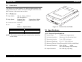
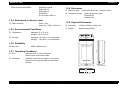
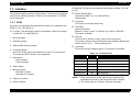
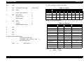
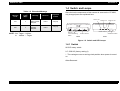
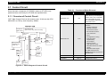
GT-9000 EPSON PRODUIT EPSON France S.A. SERVICE MANUAL 6(59,&(0$18$/ Color Imaging Scanner EPSON GT-9600 ® SESC98003 Notice All rights reserved. No part of this manual may be reproduced, stored in a retrieval system, or transmitted in any form or by any means electronic, mechanical, photocopying, or otherwise, without the prior written permission of SEIKO EPSON CORPORATION. All effort have been made to ensure the accuracy of the contents of this manual. However, should any errors be detected, SEIKO EPSON would greatly appreciate being informed of them. The contents of this manual are subject to change without notice. All effort have been made to ensure the accuracy of the contents of this manual. However, should any errors be detected, SEIKO EPSON would greatly appreciate being informed of them. The above not withstanding SEIKO EPSON CORPORATION can assume no responsibility for any errors in this manual or the consequences thereof. EPSON is a registered trademark of SEIKO EPSON CORPORATION. General Notice: Other product names used herein are for identification purpose only and may be trademarks or registered trademarks of their respective owners. EPSON disclaims any and all rights in those marks. Copyright © 1998 SEIKO EPSON CORPORATION. Printed in Japan. PRECAUTIONS Precautionary notations throughout the text are categorized relative to 1)Personal injury and 2) damage to equipment. DANGER Signals a precaution which, if ignored, could result in serious or fatal personal injury. Great caution should be exercised in performing procedures preceded by DANGER Headings. WARNING Signals a precaution which, if ignored, could result in damage to equipment. The precautionary measures itemized below should always be observed when performing repair/maintenance procedures. DANGER 1. ALWAYS DISCONNECT THE PRODUCT FROM THE POWER SOURCE AND PERIPHERAL DEVICES PERFORMING ANY MAINTENANCE OR REPAIR PROCEDURES. 2. NO WORK SHOULD BE PERFORMED ON THE UNIT BY PERSONS UNFAMILIAR WITH BASIC SAFETY MEASURES AS DICTATED FOR ALL ELECTRONICS TECHNICIANS IN THEIR LINE OF WORK. 3. WHEN PERFORMING TESTING AS DICTATED WITHIN THIS MANUAL, DO NOT CONNECT THE UNIT TO A POWER SOURCE UNTIL INSTRUCTED TO DO SO. WHEN THE POWER SUPPLY CABLE MUST BE CONNECTED, USE EXTREME CAUTION IN WORKING ON POWER SUPPLY AND OTHER ELECTRONIC COMPONENTS. WARNING 1. REPAIRS ON EPSON PRODUCT SHOULD BE PERFORMED ONLY BY AN EPSON CERTIFIED REPAIR TECHNICIAN. 2. MAKE CERTAIN THAT THE SOURCE VOLTAGES IS THE SAME AS THE RATED VOLTAGE, LISTED ON THE SERIAL NUMBER/ RATING PLATE. IF THE EPSON PRODUCT HAS A PRIMARY AC RATING DIFFERENT FROM AVAILABLE POWER SOURCE, DO NOT CONNECT IT TO THE POWER SOURCE. 3. ALWAYS VERIFY THAT THE EPSON PRODUCT HAS BEEN DISCONNECTED FROM THE POWER SOURCE BEFORE REMOVING OR REPLACING PRINTED CIRCUIT BOARDS AND/OR INDIVIDUAL CHIPS. 4. IN ORDER TO PROTECT SENSITIVE MICROPROCESSORS AND CIRCUITRY, USE STATIC DISCHARGE EQUIPMENT, SUCH AS ANTI-STATIC WRIST STRAPS, WHEN ACCESSING INTERNAL COMPONENTS. 5. REPLACE MALFUNCTIONING COMPONENTS ONLY WITH THOSE COMPONENTS BY THE MANUFACTURE; INTRODUCTION OF SECOND-SOURCE ICs OR OTHER NONAPPROVED COMPONENTS MAY DAMAGE THE PRODUCT AND VOID ANY APPLICABLE EPSON WARRANTY. About This Manual This manual describes basic functions, theory of electrical and mechanical operations, maintenance and repair procedures of GT-9600. The instructions and procedures included herein are intended for the experienced repair technicians, and attention should be given to the precautions on the preceding page. Contents Symbols Used in This Manual This manual consists of six chapters and Appendix. CHAPTER 1. PRODUCT DESCRIPTIONS Provides a general overview and specifications of the product. CHAPTER 2. OPERATING PRINCIPLES Describes the theory of electrical and mechanical operations of the product. CHAPTER 3. DISASSEMBLY AND ASSEMBLY Provides the step-by-step procedures for disassembling and assembling the product. CHAPTER 4. TROUBLESHOOTING Describes the step-by-step procedures for the troubleshooting. CHAPTER 5. ADJUSTMENTS Provides Epson-approved methods for adjustment. CHAPTER 6. MAINTENANCE Provides preventive maintenance procedures and the lists of Epson-approved lubricants and adhesives required for servicing the product. APPENDIX Provides the following additional information for reference: • Connector pin assignments • Electric circuit boards components layout • Exploded diagram • Electrical circuit boards schematics Various symbols are used throughout this manual either to provide additional information on a specific topic or to warn of possible danger present during a procedure or an action. Be aware of all symbols when they are used, and always read WARNING, CAUTION or NOTE messages. Indicates an operating or maintenance procedure, practice or condition that, if not strictly observed, could result in injury or loss of life. C A U T IO N C H E C K P O IN T Indicates an operating or maintenance procedure, practice, or condition that, if not strictly observed, could result in damage to, or destruction of, equipment. May indicate an operating or maintenance procedure, practice or condition that is necessary to accomplish a task efficiently. It may also provide additional information that is related to a specific subject, or comment on the results achieved through a previous action. Revision Status Revision Rev. A Issued Date December 2, 1998 Description First Release EPSON GT-9600 Revision A Table of Contents Product Description Disassembly and Assembly Overview......................................................................................................... 3 Features .................................................................................................... 3 Disassembly and Assembly ......................................................................... 14 Bottom Plate Removal ............................................................................ 14 B035 Power Supply Board Removal ....................................................... 14 B077 MAIN Board Removal .................................................................... 15 CR Motor Removal.................................................................................. 16 Lamp Assembly Removal ....................................................................... 17 Specifications ................................................................................................. 3 General Specifications .............................................................................. 3 Electrical Specification .............................................................................. 4 Safety, EMC .............................................................................................. 4 Resistance to electric noise....................................................................... 5 Environmental Conditions ......................................................................... 5 Reliability ................................................................................................... 5 Operating Conditions................................................................................. 5 Document .................................................................................................. 5 Physical Dimension ................................................................................... 5 Interface.......................................................................................................... 6 SCSI .......................................................................................................... 6 Switch and Lamps .......................................................................................... 8 Switch........................................................................................................ 8 Error .......................................................................................................... 9 Cause and Remedy when errors happen....................................................... 9 Command Specification.................................................................................. 9 Control Code .................................................................................................. 9 Control Code ............................................................................................. 9 Function of Control Codes......................................................................... 9 Resolution Setting .......................................................................................... 9 Download color correction .............................................................................. 9 Set Threshold ................................................................................................. 9 Set Film Type ................................................................................................. 9 Adjustment Adjustment ................................................................................................... 20 Troubleshooting Maintenance Appendix Scanner Connection ..................................................................................... 26 Connector ..................................................................................................... 26 Board Component Layout ............................................................................ 28 Exploded Diagram........................................................................................ 29 Circuit Shematics ......................................................................................... 33 Main Components ........................................................................................ 10 B077 Main Board..................................................................................... 10 B077 ISN Board ...................................................................................... 10 Operating Principles Control Circuit............................................................................................... 12 Overview of Control Circuit...................................................................... 12 1 &+$37(5 PRODUCT DESCRIPTION EPSON GT-9600 Revision A 1.1 Overview This scanner is a revised model of GT-9500 and high-resolution color image scanner for the various use from the designer to the office user. Main features of this scanner are as follow. 1.1.1 Features High Quality: 800 dpi, 12bit-in, 12bit-out OD Value MAX 3.3 High Speed: Exposure Time Scanning Time 7.5msec/line at 800dpi 75 Sec/A4, Full color Command Level: ESC/I-B8 I/F: SCSI Figure 1-1. Exterior View of GT-9600 Table 1-1. Optional Items No. Name B81316* ADF(Auto Document Feeder) B81315* TPU (Transparency Uni) 1.2 Specifications 1.2.1 General Specifications NOTE: * The number represented by an asterisk varies, depending on the country. Product Type* Flatbed color image scanner Sub-scanning device: Movement of the Scanning Head Photoelectric device: Color CCD Line Sensor Maximum Read Area: 8.5 x 11.7 (216 x 297 mm) Maximum Effective Picture Element:6800 x 9360 pixels(800dpi) Product Description Scanning Resolution: Main 800 dpi optical Sub Max.3200 dpi with microstep Output Resolution: 50 ∼ 6400 dpi (1 dpi step) Overview 3 EPSON GT-9600 Revision A Scanning Speed(600 dpi, Draft Mode): Color 7.5 msec/line Monochrome(bi-level) 7.5 msec/line Color Separation: By the color filter of CCD Command Level: ESC/I-B8 Zoom: 50% to 200% (1% step) Pixel depth: 1-12 bits/pixel (Input 12 bits/pixel) Rated Voltage: AC100-120V/220V-240V Input Voltage: AC100 -120V ±10% AC220 -240V ±10% Rated Current: 0.8A(Input AC 100V) 0.4A(Input AC 220V) Rated Frequency Range:50-60 Hz Input Frequency Range: 49.5-60.5 Hz Gamma Correction: CRT 2 level (A, B) PRINTER 3 level (A, B, C) User defined 1 level Color Correction: 1.2.2 Electrical Specification Impact-Dot Printer Thermal Printer Ink-Jet Printer CRT Display Brightness: User defined Line Art: 7 Level Fixed threshold Digital half-toning: TET AAS Bi-level, Quad-level: Power consumption: Approx.40W Insulation Resistance: 10M Ohms at 500 VDC(between AC line and chassis) Dielectric strength: AC 1.5kV, 1 min (between AC Line and chassis) 1.2.3 Safety, EMC Safety: UL1950 (UL) CSA C22.2 NO.950 (CSA) EN60950 (VDE) EN60950 + Nordic deviation(NEMKO) EMC: FCC Part 15 Subpart B Class B CSA C108.8 Class B AS/NZS3548 Class B CISPR Pub22 Class B CNS13438 Class B Error Diffusion 3 mode (A,B,C) Dither(Resident) 4 mode(A, B, C, D) Dither(User defined) 2 mode (A, B) Interface(Resident): SCSI(50-pin Half pitch Connectors) Light Source: White Cold cathode Fluorescent Lamp Option: TPU, ADF Product Description CE Marking: Low Voltage Directive 73/23/EEC Specifications EN60950 4 EPSON GT-9600 Revision A EMC Directive 89/336/EEC 1.2.8 Document EN55022 Class B EN61000-3-2 EN61000-3-3 EN 50082-1 EC 801-2/801-3/801-4 Reflective type: Documents which has a smooth surface Transparency type: (With transparency unit) Reversal film Negative film 1.2.4 Resistance to electric noise Panel - 10kv Metal-7kV /150pF, 150 Ohms 1.2.5 Environmental Conditions Temperature Operating: 5 °C to 35 °C Storage: -25 °C to 60 °C Humidity Operating: 10 to 80%, no condensation Storage: 10 to 85%, no condensation 1.2.9 Physical Dimension Dimension 332(W) x 562(D) x 134(H) mm Weight Approximately 8.5Kg O F F O N O P T IO N S C S I ID T E R M IN A T O R S W U N L O C K L O C K Static electricity: 1.2.6 Reliability Main unit MCBF 100000 cycle 5 6 2 m m 1.2.7 Operating Conditions Dust Ordinary office or home conditions. Extreme dust should be avoided. Illumination Operation under direct sunlight or near strong light source is not guaranteed and should be avoided. 1 3 4 m m 3 3 2 m m E R R O R R E A D Y O P E R A T E R E S E T Product Description Specifications O P E R A T E 5 EPSON GT-9600 Revision A 1.3 Interface SCAM(SCSI Configured Auto Matically specification) [ANSI T10/1142 rev.15] This section explains interface of this scanner. This scanner is equipped with SCSI as standard interface. Refer to Service Manual of GT-9500 for pin alignment. Electric Specification Compliant to ANSI X3. 131-1994 (SCSI 2) Single ended 1.3.1 SCSI Connector Two 50-pin connectors (Half Pitch) Any items not included in this specification shall be in compliance with ANSI X3. 131-1994 (SCSI 2). Function: The following functions are available, which are included in ANSI X3. 131-1994 (SCSI 2). 1. Bus free phase 2. Arbitration phase 3. Selection/Re-selection phase 4. Command phase Note) The LUN(Logical Unit Number) is fixed at “0” in this device. The command Link Function is not supported. Terminator Internal terminator Enable to control “active” or “inactive” by a switch. (SW=ON --Terminator available) SCSI ID The SCSI ID is set with a rotary switch on the rear panel. The switch numbers are corresponded to the available address and can be set from 0 to 7. Factory setting ID=2. Command This device use the following group “0” processor commands. Table 1-2. Command List Command 5. Data phase Data in phase Data out phase 6. Status phase 7. Message phase Message in phase Message out in phase 8. Attention condition 9. Reset condition Product Description Code Description Test Unit Ready 00h Confirm for operation Request Sense 03h Require a Sense data*1 Receive 08h Data transmission from Target to Initiator Send 0Ah Data Transmission from Initiator to Target Inquiry 12h Require information of SCSI devise*2 Send Diagnostic 1Dh Send diagnostic NOTE: *1 Only the extension sense data format is supported for sense data returned by the Request Sense Command. *2 The Inquiry data is as follows. (see the next page) Interface 6 EPSON GT-9600 Revision A Status: All bits are defined as follows. byte data 0 03h Peripheral devise type: : 3(Processor) 1 00h RMB : :0 device Type restriction: :0 ISO Version ECMA Version : : :0 :0 ANSI Version : :2 AENC : :0 TrmI0P : Response data format: :0 :2 2 3 02h 02h Table 1-3. Status Status Bits Status 7 6 5 4 3 2 1 0 Good R R 0 0 0 0 0 R Check Condition R R 0 0 0 0 1 R Busy R R 0 0 1 0 0 R NOTE: R: means reserved bit. Table 1-4. Message Message Code Direction Completion of ATN Command Complete 00h In -- Extended Messages 01h In/Out -- Save Data Pointer 02h In -- 4 23h 5 00h 6 00h Restore Pointer 03h In -- 7 00h Disconnect 04h In -- Initiator Detect Error 05h Out Yes Abort 06h Out Yes Message Reject 07h In/Out Yes(Out) No Operation 08h Out Yes Message Parity Error 09h Out Yes Bus Device Reset 0Ch Out Yes 80h-FFh In/Out No(Out) Vender unique parameter byte: ’EPSON’, 20h, 20h, 20h ’SCANNER’, 20h, ’xxxxxxxx’, 20h, ’****’, 00h, 00h, 00h, FFh] Note: ’****’ ROM version Identify NOTE: Out: Target → Initiator In: Initiator → Target Product Description Interface 7 EPSON GT-9600 Revision A 1.4 Switch and Lamps Table 1-5. Extended Message Extended Message Code Message length (Byte) Message Direction Completion of ATN 01H 5 Synchronous Data Transfer Request In/Out Yes(out) 4 Write Data Transfer Request 03H Since the basic components of this scanner is same as the GT-9500, only changed parts are explained here. R E A D Y L E D L E D O P E R A T E L E D L O C K U N L O C K In/Out E R R O R Yes(out) O P T IO N T E R M IN A T O R S W S C S I ID O N E R R O R R E A D Y O P E R A T E R E S E T O P E R A T E O F F NOTE: Out: Target → Initiator In: Initiator → Target S C S I ID T e r m in a to r S e ttin g S w itc h S C S I ID S w itc h B a c k R E S E T S w itc h O P E R A T E S w itc h F ro n t Figure 1-2. Switch and LED Lamps 1.4.1 Switch SCSI ID rotary switch: 0-7: SCSI-ID (factory setting 2) *: The carriage moves to carriage lock position when power is turned on. Other:Reserved Product Description Switch and Lamps 8 EPSON GT-9600 Revision A 1.4.2 Error 1.6 Control Code 1.4.2.1 Cause and Remedy when errors happen Since the basic components of this scanner is same as the GT-9500, only newly added or changed codes are listed here. Fatal Errors [Remedy] 1.6.1 Control Code Remove the causes and turn back on the power. Send ESC @ code. Table 1-6. Newly Added Codes Classification Send Bus Device Reset Message of SCSI. Image Processing Assert RST signal of SCSI. Support, other Function Code Download color correction ESC m d1...d9 Set Threshold ESC t i Set Film Type ESC N i 1.5 Command Specification 1.6.2 Function of Control Codes Refer to the Service Manual of GT-9500. 1.6.2.1 Resolution Setting By this command, the resolution can be set from 50 dpi to 400dpi. 1.6.2.2 Download color correction By this command, color correction can be set. 1.6.2.3 Set Threshold Controls the threshold values 1.6.2.4 Set Film Type Sets the color balance when reading the target by using TPU. Product Description Command Specification 9 EPSON GT-9600 Revision A 1.7 Main Components B077 Main Board: Main Control Board B077 ISN Board: Sensor Circuit Board B035 PSB Board: Power Supply Board Scanner Head (Carriage Assembly) Carriage Mechanism Housing Document Cover Since the basic components of this scanner is same as the GT-9500, only changed parts are explained here. 1.7.1 B077 Main Board The main control circuit, B077 Main Board controls various parts by 16bit CPU M8S/2350 Clock Frequency 20 MHz. Also, gate array and memory for image processing and motor drive circuit for moving the scanner head are also mounted on this board. 1.7.2 B077 ISN Board This board converts the signal(Analog signal) read by Color CCD sensor into the digital and sends it to the Main Board. Product Description Main Components 10 &+$37(5 OPERATING PRINCIPLES EPSON GT-9600 Revision A 2.1 Control Circuit Table 2-1. Functions of Major Elements Since the basic component of GT-9600 is same as GT-9500, only particular items exclusively for GT-9600 are explained here. Elements Location Function IC5 This CPU controls this scanner and is driven by clock frequency 20 MHz. Also, CPU control light source and timing for motor drive. EEPROM and EPROM are connected to CPU. MERCURY GA IC12 This gate array has following functions. • Shading Correction • Gamma Correction • CCD Sensor Control • A/D Convertor Control • Color Correction • Zoom • Set Digital Half -Toning • AAS (Auto area segmentation) • CPU Support Memory Control Light quantity Control • Generates Power On, Reset signals • Generates Clock signal Six 1Mbit SRAM and two 128Mbit DRAM are connected to this gate array. A64154FP IC6 SCSI Controller A3956SLB IC26, 27 2.1.1 Overview of Control Circuit H8S/2350 CPU B077 Main Control Circuit in this scanner uses “16-bit one chip CPU H8S/2350” as CPU by clock frequency 20Mhz. B 0 7 7 IS N B o a rd ( C o lo r C C D , A m p .,A /D In v e rto r fo r lig h t s o u r c e L ig h t S o u r c e C o n tro l H P S e n s o r C P U H 8 S /2 3 5 0 (IC 5 ) C R M o to r S C S C o n M 6 4 (IC 2 I tr o lle r 1 5 4 F P 1 ) S C S I Im a g e D a ta C o n tro l G a te A rra y M E R C U R Y (IC 1 2 ) B u s L in e M o to r C o n tr o lle r A 3 9 5 6 S L B X 2 (IC 2 6 , 2 7 ) C C D C o n v e rto r) 1 M b it S R A M (IC 1 5 , 1 6 , 1 9 , 2 0 , 2 2 , 2 3 ) 1 M b it D R A M (IC 8 , 1 8 ) 1 M b it P R O M (IC 6 ) 2 5 6 K b it S R A M (IC 7 ) Carriage Motor Driver O p tio n C o n n e c to r Figure 2-1. Block Diagram of Control Circuit Operating Principles Control Circuit 12 &+$37(5 DISASSEMBLY AND ASSEMBLY EPSON GT-9600 Revision A 3.1 Disassembly and Assembly 3.1.2 B035 Power Supply Board Removal This section explains disassembly procedure of GT-9600. Since the components of GT-9500 and GT-9600 are basically same, items only for GT-9600 are explained here. 3.1.1 Bottom Plate Removal 1. Remove “Bottom Plate”. (See “Bottom Plate Removal” on page -14) 2. Disconnect harness from the connectors on the B035 power supply board. 3. Remove 5 screws (CBB, 3x12) securing B035 power supply board to “Housing, Lower”. 1. Remove 17 screws(CBB, 3x12) and 2 screws(CBS, 3x6) securing “Bottom Plate” to “Housing, Lower”. 4. Remove B035 power supply board from “Housing, Lower”. 2. Remove “Bottom Plate” from “Housing, Lower”. Power Supply Cable CBB(3x12) CBB (3x12) CBS (3x6) Harness to B077Main Board Housing Lower Harness to the LED Board Figure 3-2. B035 Power Supply Board Removal CBB(3x12) Figure 3-1. Bottom Plate Removal Disassembly and Assembly Disassembly and Assembly 14 EPSON GT-9600 Revision A 3.1.3 B077 MAIN Board Removal 1. Remove Bottom plate. ( See “Bottom Plate Removal” on page -14) CBS(M3x6) 2. Remove one screw(CBB, 3x12) securing FFC earth plate to “Housing, Lower”, and remove FFC earth plate. 3. Remove harness from the connectors(CN1, CN2, CN3 and CN4) on the B077 Main Board. B077Main Board 4. Remove 2 screws(CBS, M 3x6) securing “B077 Main Board” to “Shield Plate, Rear”. 5. Remove “B077 Main Board”. 6. Remove 4 screws (CP, M2.5 X 8) securing “Interface Cover” and “B077 Main Board”. CBB (3x12) FFC Earth Plate 7. Remove “Interface Cover” from B077 Main Board. Figure 3-3. B077Main Board Removal CP(M2.5 x 8) Figure 3-4. Interface Cover Removal Disassembly and Assembly Disassembly and Assembly 15 EPSON GT-9600 Revision A 3.1.4 CR Motor Removal 5. Remove carriage assembly. (Refer to Service Manual of GT-9500) 1. Remove “Housing, Upper”. (Refer to Service Manual of GT-9500) 2. Remove Bottom plate. (See “Bottom Plate Removal” on page -14) 6. Remove 3 screws(CBB, 3x12) securing “Center Rail” to “Housing, Lower”, and one screw (CBS, M3x6) securing “Center Rail” to “CR Motor Frame”. 3. Remove B077 Main Board. (See “B077 MAIN Board Removal” on page -15) 7. Remove 2 screws(CBS, M3x6) securing “Earth Plate, Front” and “Frame, Front”, and remove “Center Rail”. 4. Remove 5 screws(CBS, M3x6) securing “Center Rail” and “Shield Board” from the back of scanner. Also, remove one screw(CB, 3x6) securing “CR Motor Assembly”, earth plate, and motor from the back of scanner. Housing, Lower Earth Plate, Front Center Rail CB(3x6) Frame, Front CBS(M3x6) CBB(3x12) CBS(M3x6) Figure 3-6. Center Rail Removal Figure 3-5. Screws at the Circuit Board Side Removal Disassembly and Assembly Disassembly and Assembly 16 EPSON GT-9600 Revision A 8. Remove one screw(CBB, 3x12) securing the motor, and remove the motor. 3.1.5 Lamp Assembly Removal 1. Remove carriage assembly. (Refer to Service Manual of GT-9500) 9. Loosen a screw(CBS, M3x6) securing the “Tension Lever Assembly” to “Motor Frame”, move “Lever Assembly, Tension” to the arrowed direction, releasing the tension of the timing belt of CR motor. Then, remove “Timing Belt B”. 10. Remove 3 “Shaft, Damper, CR” and remove “CR Motor” from “Motor Frame”. CBS(M3x6) CBB(3x12) 2. Remove 2 screws(CB, M3x6) securing “Cover, Rear, Carriage” to “Carriage Assembly”, and remove “Cover, Rear, Carriage”. 3. Remove 3 screws (CB, M 3x6) securing “Cover, Carriage” to “Carriage Assembly”, and remove “Cover, Carriage”. One screw(CB, M3x8) under “Cover, Rear, Carriage”. CR Motor Assembly Figure 3-7. CR Motor Assembly Removal CB(M3x6) Figure 3-8. Carriage Cover Removal Disassembly and Assembly Disassembly and Assembly 17 EPSON GT-9600 Revision A 4. Remove 2 screws(CB, 3x6) securing “Invertor Board” to “Carriage Assembly”. Lift up “Invertor Board” and remove the harness of “Lamp Assembly” from the connector on the “Invertor Board”. 5. Remove “Lamp Assembly”. CB(3x6) Lamp Assembly Figure 3-9. Lamp Assembly Removal Disassembly and Assembly Disassembly and Assembly 18 &+$37(5 ADJUSTMENT EPSON GT-9600 Revision A 4.1 Adjustment Origin Adjustment required for GT-9500 is not necessary for GT-9600. Adjustment Adjustment 20 &+$37(5 TROUBLESHOOTING EPSON GT-9600 Revision A Refer to Service Manual of GT-9500. Troubleshooting 22 &+$37(5 MAINTENANCE EPSON GT-9600 Revision A Refer to Service Manual of GT-9500. Maintenance 24 &+$37(5 APPENDIX EPSON GT-9600 Revision A 7.1 Scanner Connection 7.2 Connector A C IN O p tio n S C S I S C S I C N 1 C N 7 C N 6 C N 5 Table 7-1. Connector B 0 3 5 P o w e r S u p p ly C ir c u it B o a r d C N 2 This section explains the connectors connected to the circuit boards and their locations. Table 7-2 and 7-3 show signal name of each connector and its description. Also, since the basic component of GT9500 and GT-9600 are same, items only for GT-9600 are explained here. Board Name B 0 7 7 M a in C ir c u it B o a r d C N 3 C N 1 C N 3 C N 4 C N 2 B077 Main Board In v e rto r C ir c u it B o a r d L ig h t S o u r c e L a m p L E D B o a rd B 0 7 7 IS N (C C D ) B o a rd S c a n n e r H e a d C R M o to r Connector Pin Number Content CN 1 39 Scanner Head CN 2 3 HP Sensor CN 3 12 B077 PSB Power supply Board CN 4 4 CR Motor CN 5 50 SCSI CN 6 50 SCSI CN 7 15 Option H P S e n s o r Figure 7-1. Internal Connection Appendix Scanner Connection 26 EPSON GT-9600 Revision A Table 7-2. Connector Pin Table 7-3. Connector Pin Pin. No. Signal Name I/O Pin. No. Signal Name I/O 1-2 +24 -- +24 VDC 1-12 GND -- GND 3 LAMP O Lamp Control Signal 13 -- -- Not Used 4-5 PGND --- GND 14-25 GND --- GND 6 -- O Not Used 26-33 SD0-7 I/O SCSI Data Line 0-7 7 GND O GND 34 SDP I/O Parity Line for SCSI Data 8-9 +12 O +12 VDC 35-37 GND -- 10 GND O GND 38 TERMPWR I/O 11-12 +5 O +5VDC 39-40 GND -- GND 13 SHB O Shutter control for CCD blue sensor 41 /ATN I Attention Signal of SCSI 14 SHG O Shutter control for CCD green sensor 42 GND -- GND 15 SHR O Shutter control for CCD red sensor 43 /BSY I/O 16 RST O Reset 44 /ACK I ACKNOWLEDGE signal of ACSI 17 CK1 O Clock 1 45 /RST I RESET signal of ACSI 18 TG O CCD Shift Pulse 46 /MSG O MESSAGE signal of ACSI 19 ADCK O ADC Clock 47 /SEL I/O SELECT signal of SCSI 20-21 CDS1-2 O ADC CDS signal 48 /CD O CONTROL DATA signal of SCSI 22 CLP O ADC CLP Signal 49 /REQ O REQUEST signal of SCSI 23 WR O ADC Serial Data Latch Signal 50 /IO O INPUT/OUTPUT signal of SCSI 24 SD O ADC Serial Data 25 SCK O ADC Serial Data Clock 26 GND --- GND 27-38 AD 0-11 I Video Data Bit 0-11 39 GND -- GND Appendix Description Connector Description GND Terminal Power Supply (+5VDC) BUSY signal of SCSI 27 EPSON GT-9600 Revision A 7.3 Board Component Layout Figure 7-3. B077 Main Board Component Layout(Soldered Side) Figure 7-2. B077 Main Board Component Layout Appendix Board Component Layout 28 EPSON GT-9600 Revision A 7.4 Exploded Diagram Following pages show exploded diagram of GT-9600. Exploded Diagram 1 Exploded Diagram 2 Exploded Diagram 3 Appendix Exploded Diagram 29 EPSON GT-9600 Revision A 7.5 Circuit Shematics Following pages show the electric circuits of this scanner. B077 Main Board B077ISN Board Appendix Circuit Shematics 33