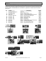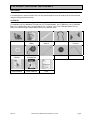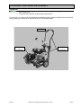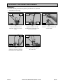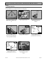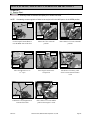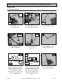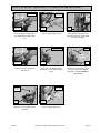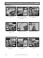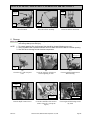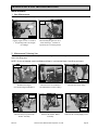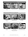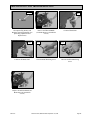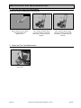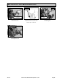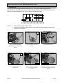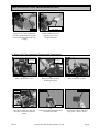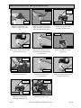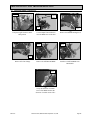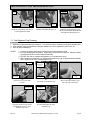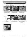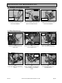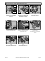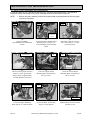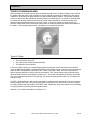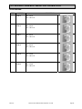
1
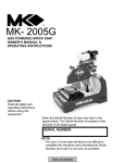
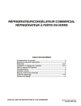
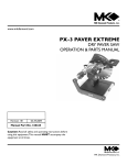
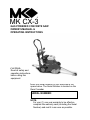
MK CX-3
GAS POWERED CONCRETE SAW
OWNER’S MANUAL &
OPERATING INSTRUCTIONS
CAUTION:
Read all safety and
operating instructions
before using this
equipment
Enter the Serial Number of your new saw in the
space below. The Serial Number is located on the
Rear Crossbar
SERIAL NUMBER:
NOTE:
For your (1) one year warranty to be effective
complete the warranty card (including the Serial
Number) and mail it in as soon as possible.
INTRODUCTION and TABLE OF CONTENTS
INTRODUCTION:
We at MK Diamond want to congratulate you on selecting the MK CX-3 Concrete Saw. We are certain that
you will be pleased with your purchase. MK Diamond takes pride in producing the finest products in the
industry.
Operated correctly, your MK CX-3 should provide you with years of quality service. In order to help you, we
have included this manual. This owner’s manual contains information necessary to operate and maintain
your MK CX-3 safely and correctly. Please take a few minutes to familiarize yourself with the MK CX-3 by
reading and reviewing this manual.
If you should have questions concerning your MK CX-3, please feel free to call our friendly customer service
department at: 800 421-5830
TABLE OF CONTENTS
Page
SAFETY:
Safety Messages
Damage Prevention Message
General Safety Precautions and Hazard Symbols
California Proposition 65 Message
Safety Label Locations
Brick Saw Specific Warnings
Product Specifications
3
3
3
5
6
7
7
UNPACKING AND ASSEMBLY
Unpacking
Contents
Transport
Assembly
8
8
9
10
SETUP, STARTUP, ADJUSTMENT AND OPERATION
Setup
Start Up
Adjustment and Operation
Cleanup
15
16
17
20
MAINTENANCE AND TROUBLESHOOTING
Maintenance
21
EXPLODED VIEW AND PARTS LIST
Exploded View
Parts List
37
38
THEORY
Theory of Diamond Blades
42
ACCESSORIES, ORDERING and RETURN INSTRUCTIONS
Accessories
Ordering Information
Return Material Policy
Packaging Instructions
Authorized Service Centers
43
44
44
44
44
Manual Part No. 159348
MK CX-3
Revision 07/15
Revision 09/04, Effective Date September 17, 2004
Page 2
SAFETY
Read and follow all safety, operating and maintenance instructions. Failure to read and follow these
instructions could result in injury or death to you or others. Failure to read and follow these instructions could
also result in damage and/or reduced equipment life.
SAFETY MESSAGES:
Safety messages inform the user about potential hazards that could lead to injury, death and/or equipment
damage. Each safety message will be preceded by one of the following (3) three words that identify the
severity of the message.
Not following instructions WILL lead to DEATH or SERIOUS INJURY
Not following instructions COULD lead to DEATH or SERIOUS INJURY
Not following instructions CAN lead to injury
DAMAGE PREVENTION AND INFORMATION MESSAGES:
A Damage Prevention Message is to inform the user of important information and/or instructions that could
lead to equipment or other property damage if not followed. Information messages convey information that
pertains to the equipment being used. The word note, as in the example below will precede each message.
NOTE: Equipment and/or property damage may result if these instructions are not followed.
GENERAL SAFETY PRECAUTIONS AND HAZARD SYMBOLS:
In order to prevent injury, the following safety precautions and symbols should be followed at all times!
Safety Precautions:
KEEP GUARDS IN PLACE.
In order to prevent injury, keep guards in place and in working order at all times.
EXPLOSIVE FUEL!
Gasoline is extremely flammable, its vapors can explode if ignited; store only in approved containers,
in well-ventilated, unoccupied buildings and away from sparks or flames. Do not fill the fuel tank while
the engine is running or hot. Spilled fuel could ignite if it contacts hot parts or sparks from ignition. Do
not start the engine near spilled fuel. Never use gasoline as a cleaning agent.
LETHAL EXHAUST GASES!
Engine exhaust gasses contain poisonous carbon monoxide, an odorless colorless gas that can cause
death if inhaled. Avoid inhaling exhaust fumes, and never run the engine in a closed building or
confined area.
ELECTRICAL SHOCK!
Never touch electrical wires or components while the motor is running. Exposed, frayed or worn
electrical motor wiring can be sources of electrical shock that could cause severe injury or burns.
((
ENGINE OVER-SPEED.
)) Never tamper with the governor components or settings to increase the maximum speed of the
machine. Severe personal injury and/or equipment damage could result if the equipment is operated
speeds above design maximum.
MK CX-3
Revision 09/04, Effective Date September 17, 2004
Page 3
SAFETY
ACCIDENTAL STARTS!
on Before starting the engine, be sure the ON/OFF switch is in the "OFF" position to prevent accidental
starting. Place the ON/OFF switch in the OFF position before performing any service operation.
ROTATING OR MOVING PARTS!
Keep hands, feet, hair, and clothing away from all moving parts to prevent injury. Never operate a
power tool with shrouds or guards removed.
HOT PARTS!
Engine components can become extremely hot from operation. To prevent severe burns, do not touch
these areas while the engine is running, or immediately after it is turned off. Never operate the engine
with heat shields removed.
ALWAYS USE SAFETY GLASSES!
Safety glasses should always be worn when working around power tools. Everyday eyeglasses only
have impact resistant lenses and may not prevent eye injury; they are NOT safety glasses.
ALWAYS USE RESPIRATORY PROTECTON!
Exhaust gases may be harmful if inhaled. Do not operate gas-powered equipment in enclosed
spaces. Respiratory protection should be worn when operating gas-powered equipment.
ALWAYS USE HEARING PROTECTION!
To reduce the possibility of hearing loss, always use hearing protection when operating equipment.
REMOVE ADJUSTING KEYS AND WRENCHES.
Form a habit of checking to see that keys and adjusting wrenches are removed from the power tool before it
is turned on.
KEEP WORK AREA CLEAN.
Cluttered work areas and benches invite accidents.
DO NOT USE IN DANGEROUS ENVIRONMENTS.
Do not operate equipment in dangerous environments. Always keep the work area well lighted.
KEEP CHILDREN AWAY.
All visitors and children should be kept a safe distance from work area.
MAKE WORKSHOP KID PROOF.
Make the workshops kid proof by using padlocks, master switches or by removing starter keys.
DO NOT FORCE THE TOOL.
A power tool will do a job better and safer operating at the rate for which it was designed.
USE THE RIGHT TOOL.
Do not force a tool or an attachment, to do a job that it was not designed to do.
WEAR PROPER APPAREL.
Do not wear loose clothing, gloves, neckties, rings, bracelets, or other jewelry that may be caught in moving
parts. Nonslip footwear is recommended. Wear protective hair covering to contain long hair.
SECURE WORK.
Clamps or a vise should be used to hold work whenever practical. Keeping your hands free to operate a
power tool is safer.
MK CX-3
Revision 09/04, Effective Date September 17, 2004
Page 4
SAFETY
DO NOT OVERREACH.
Keep proper footing and balance at all times by not overreaching.
MAINTAIN TOOLS WITH CARE.
Keep tools sharp and clean for the best and safest performance. Always follow maintenance instructions for
lubricating and when changing accessories.
SHUTDOWN TOOL.
The saw should always be shutdown before servicing or when changing accessories such as blades, bits,
cutters, and the like.
USE RECOMMENDED ACCESSORIES.
Consult the owner's manual for recommended accessories. Using improper accessories may increase the
risk of personal or by-stander injury.
NEVER STAND ON THE TOOL.
Serious injury could occur if a power tool is tipped, or if a cutting tool is unintentionally contacted.
NEVER LEAVE TOOL RUNNING UNATTENDED – TURN POWER OFF.
Do not leave a tool until it comes to a complete stop. Always turn a power tool OFF when leaving the work
area, or, when a cut is finished.
CHECK FOR DAMAGED PARTS.
Before using a power tool, check for damaged parts. A guard or any other part that is damaged should be
carefully checked to determine it would operate properly and perform its intended function. Always check
moving parts for proper alignment or binding. Check for broken parts, mountings and all other conditions
that may affect the operation of the power tool. A guard or any damaged part should be properly repaired or
replaced.
DIRECTION OF FEED.
Always feed work into a blade or cutter against the direction of rotation. A blade or cutter should always be
installed such that rotation is in the direction of the arrow imprinted on the side of the blade or cutter.
Sawing and drilling generates dust. Excessive airborne particles may cause irritation to eyes, skin and
respiratory tract. To avoid breathing impairment, always employ dust controls and protection suitable to the
material being sawed or drilled; See OSHA (29 CFR Part 1910.1200). Diamond Blades improperly used are
dangerous. Comply with American National Standards Institute Safety Code, B7.1 and, Occupational Safety
and Health Act covering Speed, Safety Guards, Flanges, Mounting Procedures, General Operating Rules,
Handling, Storage and General Machine Conditions.
CALIFORNIA PROPOSITION 65 MESSAGE:
Some dust created by power sanding, sawing, grinding, drilling, and other construction activities contain
chemicals known [to the State of California] to cause cancer, birth defects or other reproductive harm. Some
examples of these chemicals are:
• Lead, from lead-based paints
• Crystalline silica, from bricks and cement and other masonry products
• Arsenic and chromium, from chemically treated lumber
Your risk from these exposures varies depending on how often you do this type of work. To reduce your
exposure to these chemicals, work in a well-ventilated area, and work with approved safety equipment, such
as those dust masks that are specially designed to filter out microscopic particles.
For further information, consult the following sources:
http://www.osha-slc.gov/sltc/silicarystalline/index.html
http://www.oehha.org/prop65/out_of_date/6022kLstA.html
MK CX-3
Revision 09/04, Effective Date September 17, 2004
Page 5
SAFETY
SAFETY LABEL LOCATIONS:
Safety labels are located according to Figures 1 to 7 below. The labels contain important safety information.
Please read the information contained on each safety label. These labels are considered a permanent part of
your saw. Please, contact MK Diamond or your dealer for a replacement, if a label comes off or becomes
hard to read.
Item
1
2
3
4A
4B
5
6A
6B
6C
6D
7A
7B
7C
7D
Location
Console Assembly
Horizontal Frame Support
Outer Blade Guard
Inner Blade Guard
Shaft Cover
Fuel Tank – Right Side
Fuel Tank – Top
Fuel Tank – Top
Fuel Tank – Top
Fuel Tank – Front
Belt Guard
Belt Guard
Belt Guard
Belt Guard
Description
Operating and Safety Instructions
Serial Tag
Warning – Blade Failure
Caution – Do Not Lift Blade Guard
Caution – Do not Operate with Guards Removed
Warning – When Refueling Stop Engine
Danger – California Warning
Warning – Engine Mfg. Label
Caution – Hot Surface
Danger – Lethal Exhaust
Caution – Do Not Operate with Guards Removed
Caution – Accidental Start Hazard
Caution – Over tensioning Belt Hazard
Caution – Keep Hands and Feet Clear
1
3
2
A
B
B
C
D
A
5
4
B
Part No.
159208
159251
155588
155586
155587
155580
155581
N/A
155578
155582
155587
155579
155583
155585
6
6
C
A
D
7
MK CX-3
Revision 09/04, Effective Date September 17, 2004
Page 6
SAFETY
CX-3 SPECIFIC WARNINGS:
Read Owners Manual
Wear Protective Gear for –
Lungs
Ear
Eye
PRODUCT SPECIFICATIONS:
The MK CX-3 is a versatile Concrete Saw. Operated and used according to this manual, the MK CX-3 will
provide years of dependable service.
General Description:
The MK CX – 3 is engineered as a portable concrete saw powered by a 6 horsepower, Robin gas engine or a
6.5 horsepower Honda gas engine. The saw is capable of cutting up to five (5) inches in depth.
Motor and Weight Specifications:
Motor and Weight specifications for the MK CX-3 are listed in Table 2 below.
Motor Type
Max Power Output
Max RPM
Blade Speed
Fuel Tank Capacity
Engine Oil Capacity
Weight
4-stroke, Overhead valve, single cylinder
6 / 6.5 Hp
3600 RPM
3400 to 3600 RPM (Depending on Blade Diameter)
2.7 Liters
0.6 Liters
Approximately 185 lbs.
Table 2
Blade:
The MK CX-3 uses a 12 to 14 inch diameter diamond blade.
Concrete Saw Usage:
The MK CX-3 is designed to cut various grades of concrete surfaces.
Features:
• Conveniently placed engine controls for ease of usage
• Height adjusting screw designed to accurately adjust the depth of the cut
• Ergonomically designed handlebar to reduce operator fatigue
• Poly micro V-belt to ensure maximum power transfer from the engine to the blade.
MK CX-3
Revision 09/04, Effective Date September 17, 2004
Page 7
UNPACKING, TRANSPORT and ASSEMBLY
UNPACKING:
Your MK CX-3 has been shipped from the factory thoroughly inspected. Only minimal assembly is required.
If not already done, remove the MK CX-3 from the pallet and place it on a flat surface (lift the Concrete Saw
using the lifting points shown below.
CONTENTS:
In the containers, you will find one (1) MK CX-3, one (1) Diamond Blade, two (2) Blade Shaft Wrenches, one
(1) Handlebar, two (2) Handlebar Tri-knobs, two (2) Tri-Knob Washers, one (1) Ball Knob, one (1) Shoulder
Bolt, one (1) Pointer Arm, one (1) Pointer Wheel, one (1) Pointer, one (1) CX-3 Owners Manual, one (1)
Robin’s or Honda’s Engine Owners Manual and one (1) warranty card.
MK CX-3
Diamond
Blade
2 Blade Shaft
Wrench
Handlebar
Handlebar
Tri-Knob
Tri-Knob
Washer
Ball Knob &
Shoulder Bolt
Pointer Arm
Pointer Wheel
Pointer
CX-3
Owners Manual
Robin or Honda
Owner’s Manual
Warranty
Card
MK CX-3
Revision 09/04, Effective Date September 17, 2004
Page 8
UNPACKING, TRANSPORT and ASSEMBLY
TRANSPORT:
1. The MK CX-3 weighs approximately one hundred and eighty-five (185) pounds), use care
when transporting.
2. Two people are required to lift and transport the MK CX-3.
To lift the CX-3, one person will lift by grasping the Handlebar (either extended or folded) and one person will
lift by grasping the Lifting Rung on the front of the CX-3 as identified below.
Lift Points
Lifting Rung
Lift Point
MK CX-3
Handlebar
Lift Point
Revision 09/04, Effective Date September 17, 2004
Page 9
UNPACKING, TRANSPORT and ASSEMBLY
ASSEMBLY:
Follow the assembly instructions to prepare your MK CX-3 for operation.
1. Handlebar Assembly:
Console
Frame
Threaded
Hole
Handlebar
Console
Frame
(A)
Locate the threaded holes on
both sides of the CX-3 console
frame
Washer
Threaded
Hole
(B)
Align the Handlebar with the
threaded holes on the sides of the
CX-3 console frame
Tri-Knob
(C)
Install one Tri-Knob Washer onto
each Tri-Knob
Second
Tri-Knob
Threaded
Hole
Opposite
Side
(D)
Install one Tri-Knob through the
Handlebar and into the threaded
hole on the CX-3 console frame
(E)
Repeat Step “C” on the opposite
side of the CX-3
MK CX-3
Tri-Knob
Revision 09/04, Effective Date September 17, 2004
Page 10
UNPACKING, TRANSPORT and ASSEMBLY
2. Cutting Pointer Arm Installation:
Pointer Arm
Tighten
Pointer
Stop Clip, Screw,
Flat Washer and
Nut
Retaining
Clip
Pointer
Wheel
(A)
Install the Pointer Arm using the
Stop Clip, a 3/4-inch screw, flat
washer and a Nylock Nut
Retaining
Clip
(B)
Tighten the Nylock Nut and 3/4inch screw
Rotate
(C)
Install the Pointer Wheel, the
Pointer and the Pointer Retaining
Clip
Rotate
Pointer
Thumbscrew
(D)
Tighten the Retaining Clip
Thumbscrew
(E)
Rotate the Pointer Arm into the
upright position
(F)
Rotate the Pointer down
3. Diamond Blade Installation:
NOTE: When installing the diamond blade retaining-bolt, ensure the threads of the bolt are aligned with the
threads of the drive shaft so as not to “cross-thread" the bolt.
Cover
Direction
to Open
Inner and Outer
Flanges
(A)
Open the Blade Guard Cover
MK CX-3
Retaining
Screw
(B)
Locate the Blade Retaining Screw,
the Outer and the Inner Flange
Revision 09/04, Effective Date September 17, 2004
Page 11
UNPACKING, TRANSPORT and ASSEMBLY
Retaining Nut
Wrench
Shaft
Shaft
Wrench
Shaft
Wrench
(D)
Place the Blade Shaft Wrench
onto the flat section of the Blade
Shaft
Outer
Flange
Retaining Nut
Removed
(E)
Loosen the Blade Retaining Screw
while holding the Shaft Wrench
steady
Diamond
Blade
(G)
Remove the Outer Flange
(F)
Remove the Blade
Retaining Screw
Rotational
Arrow
(H)
Install the Diamond Blade onto the
Blade Shaft
(I)
Verify the direction of rotation
arrow of the Blade matches the
direction of rotation on the CX-3
Outer
Flange
Outer
Flange
(J)
Install the Outer Flange
MK CX-3
Flush Against
Blade
Blade
(K)
Verify the Outer Flange is seated
against the Blade
Revision 09/04, Effective Date September 17, 2004
Retaining
Screw
(L)
Install the Blade Retaining Screw
Page 12
UNPACKING, TRANSPORT and ASSEMBLY
4. Filling Oil Reservoir:
NOTE:
SAE 10W-30 is recommended for general use in temperatures of – 4ºF (20ºC) and above. If you
are operating outside of this range, consult the chart in this manual.
Engine Oil Capacity is 0.63 US qt (0.6l).
Oil Drain
Cap
Oil Drain
Line
Read
(A)
Read and remove caution tag
attached to the Gas Cap
Dipstick
(B)
Verify the Oil Drain Cap is
installed onto the Oil Drain Line
and is tight
Turn clockwise
to tighten
Fill through Reservoir
oil level hole
(D)
Fill the Oil Reservoir
(CAUTION: Do not overfill)
MK CX-3
Turn counterclockwise to tighten
(C)
Remove the Oil Reservoir
“Dipstick”
Wipe up
excess oil
Dipstick
(E)
Install the Oil Reservoir
“Dipstick”
Revision 09/04, Effective Date September 17, 2004
(F)
Cleanup any excess oil
Page 13
UNPACKING, TRANSPORT and ASSEMBLY
5. Filling Fuel Tank:
1. Gasoline is highly flammable and explosive. You can be burned or seriously injured when
handling fuel.
2. To fuel, stop engine if running, and allow it to cool.
3. Refuel in a well-ventilated area.
4. Keep gasoline away from appliance pilot lights, barbecues, electric appliances, power tools,
etc.
5. Wipe up spills immediately.
NOTES:
1. Fuel can damage paint and plastic. Be careful not to spill fuel when filling the fuel tank.
Damage caused by spilled fuel IS NOT covered under the warranty.
2. DO NOT use stale or contaminated gasoline, or an oil/gasoline mixture.
3. Use unleaded gasoline with a pump octane rating of 86 or higher.
Fill Throat
Fill Throat
Fuel Cap
Turn counterclockwise to
loosen
Upper Limit
(B)
Fill Fuel Tank
(A)
Remove the Fuel Cap
(C)
Verify fuel level is below
the throat of the Fuel Tank
Fuel Cap
Turn clockwise
to tighten
(D)
Install the Fuel Cap
MK CX-3
Revision 09/04, Effective Date September 17, 2004
Page 14
SETUP, STARTUP, ADJUSTMENT, OPERATION and SHUTDOWN
SETUP:
1. Pre-start Inspection:
The pre-start inspection should be performed before beginning any job.
If Diamond Blade is worn, replace the blade before starting work.
Look for leaks
(A)
Inspect Blade for damage – Verify
Blade correct for material being
cut
(B)
Inspect Engine for leaks
Verify ease of
movement
Verify ease of
movement
(D)
Verify the Height Adjusting
Wheel moves freely and the CX-3
moves up and down smoothly
(C)
Inspect the MK CX-3 for
general damage and/or loose
hardware
Proper Oil Level
Low Level
(E)
Verify the CX-3 rolls freely
(F)
Check for proper oil level
(See Maintenance section if low)
Fill Throat
Upper Limit
Air Filter
(G)
Check for proper fuel level
(See Maintenance section if low)
MK CX-3
(H)
Check Air Filter for cleanliness
(See Maintenance section
if dirty)
Revision 09/04, Effective Date September 17, 2004
Page 15
SETUP, STARTUP, ADJUSTMENT, OPERATION and SHUTDOWN
STARTUP:
2. Engine Start:
1. Carbon monoxide gas is toxic breathing it can cause unconsciousness and/or death.
2. Avoid any areas or actions that expose you to carbon monoxide.
NOTE:
If restarting a warm engine the Choke Lever may be left in the Half Open or in the OPEN position.
Rotate
clockwise
to raise
Fuel Valve
Direction of
Movement
Raise
Blade
(A)
Use the Depth Control Wheel to
raise the Blade clear of the floor
Throttle Lever
Choke Lever
(B)
Place Fuel Valve in the ON
position
Engine Switch
(C)
Place Choke Lever in the CLOSED
position
Direction of
Movement
Direction of
Movement
Starter Cord
Direction of
Movement
(D)
Move the Throttle Lever to
1/3rd open
(E)
Place Engine Switch in the
ON position
(F)
Pull Starter Cord slowly, until
slack is removed and resistance
is felt
Choke
Starter Cord
Direction of
Movement
Direction of
Movement
(G)
Pull Starter Cord straight back in
a smooth fast motion
(H)
Place Choke Lever in the OPEN
position when engine is warm
MK CX-3
Direction of
Movement
Revision 09/04, Effective Date September 17, 2004
Page 16
SETUP, STARTUP, ADJUSTMENT, OPERATION and SHUTDOWN
OPERATION:
3. Standard Operation:
The following is a brief overview of operating the CX-3.
Rotate
clockwise
to raise
Cooling
Inlet
Cooling
Supply
Blade
Raised
(A)
Verify the Blade is clear of the
operating surface
Lower
Pointer
(B)
Attach the cooling supply hose to
the Cooling Inlet of the CX-3
Retaining
Clip
Align with
Straightedge
Blade
Connect
Pointer
(D)
Using a Straightedge, align the
Pointer to the Blade
Mark
Line
Thumbscrew
(D)
Tighten the Retaining Clip
Thumbscrew
Direction
of Push
(C)
Lower the Pointer Assembly
Lift and
Move
(E)
Layout and mark the area to be cut
using a Chock-line or etc.
Start
CX-3
A
B
Pointer
Movement
Cut Line
(F)
Push the saw diagonally across the
marked cut line and stop when the
distance from the rear of the saw to
the line (distance A) and the
distance from the pointer to the line
(distance B) are approximately
equal
MK CX-3
(G)
Lift the rear wheels slightly off the
ground and swing the rear of the
saw around until the pointer and
Blade are over the line; do not tilt
the saw too far forward to keep
the Blade from contacting the
concrete
Revision 09/04, Effective Date September 17, 2004
(H)
Start the CX-3 using the Engine
Start procedure on Page 16
Page 17
SETUP, STARTUP, ADJUSTMENT, OPERATION and SHUTDOWN
Cooling
Supply Valve
Throttle Lever
Direction
to Open
Direction of
Movement
(J)
Open Cooling Supply Valve
(I)
With the engine running adjust
the throttle approximately half
way
Rotate Counterclockwise to Lower
Throttle Lever
(L)
Adjust the throttle as needed to
make the cut
(M)
Slowly lower the Blade until the
desired level is reached and begin
the cut
Rotate
clockwise
to raise
(K)
Verify proper cooling flow and
adjust the water flow on the blade
to a desired amount
Direction
of Cut
Perform
Cut
Blade
Lowered
Direction of
Movement
(N)
Perform the cut using only enough
pressure to follow the original
marked line. Do not attempt to
steer the saw
Cooling
Supply Valve
Direction
to Open
Blade
Raised
(O)
When the Cut is Complete, Raise
the Blade
MK CX-3
Verify
Flow
(P)
Close Cooling Supply Valve
Revision 09/04, Effective Date September 17, 2004
Page 18
SETUP, STARTUP, ADJUSTMENT, OPERATION and SHUTDOWN
SHUTDOWN:
4. Normal Engine Shutdown:
Rotate
clockwise
to raise
Direction of
Movement
Blade
Raised
Engine Switch
Direction of
Movement
Throttle Lever
(B)
Move the Throttle Lever to the
minimum “Slow” position to lower
the Blade speed
(A)
Raise or Verify the Blade is
raised
Fuel Valve
(C)
Place Engine Master Switch in the
OFF position
Lower
Pointer
Direction of
Movement
Raise
Pointer
(E)
Raise the Pointer Assembly
(D)
Place Fuel Valve in the OFF
position
(F)
Rotate the Pointer downward
5. Emergency Engine Shutdown:
Engine Switch
Direction of
Movement
(A)
Place Engine Master Switch in the
OFF position
MK CX-3
Fuel Valve
Direction of
Movement
Throttle Lever
(B)
Move the Throttle Lever to lower
blade speed
Revision 09/04, Effective Date September 17, 2004
Direction of
Movement
(C)
Place Fuel Valve in the OFF
position
Page 19
SETUP, STARTUP, ADJUSTMENT, OPERATION and SHUTDOWN
Rotate
clockwise
to raise
Lower
Pointer
Raise
Pointer
Blade
Raised
(D)
Raise the Blade
(E)
Raise the Pointer Assembly
(F)
Rotate the Pointer downward
6. Cleanup:
Engine parts are extremely hot following use, allow engine to cool 1/2-hour before cleaning. Use
care during cleanup to avoid injury.
NOTE: 1. To extend operating life, the Concrete Saw should be cleaned following every use.
2. Using a garden hose or pressure washer can force water into the air cleaner or muffler opening.
3. Use care when cleaning around electrical components.
Depth Control
Wheel Bearing
Engine Off
Soap and
Water
(A)
Clean the CX-3 with soap and
water
(B)
Verify the engine is off and cool
before beginning to clean
(C)
Clean around the Depth Control
Wheel bearing
Clean Exterior
Surfaces
Throttle Linkage
Depth Control
Screw
(D)
Clean the Depth Control Screw
MK CX-3
(E)
Clean the remainder of the exterior
surface of the CX-3 (except the
engine)
Revision 09/04, Effective Date September 17, 2004
(F)
Clean engine throttle linkage with a
dry cloth
Page 20
MAINTENANCE AND TROUBLESHOOTING
MAINTENANCE:
1. New Maintenance:
Perform the following after initial purchase and operation of the saw.
Inspect
V-belt
Change Oil
(A)
Change engine oil after 1st month or
1st 20 operating hours (See Engine
Oil Change)
(B)
Check and adjust tension on all Vbelts following 1st 48 hours of
operation (See V-belt Inspection)
2. Maintenance Following Use:
The following maintenance should be performed following each use. Use Light oil, such as WD-40 or 3 in 1
when lubricating parts.
NOTE: Due to the material used in the Blade and Shaft, it is critical that Steps C and D be performed.
Engine Off
Grease
Fitting
Air Filter
(A)
Shutdown the Engine
(See Normal Engine Shutdown)
Pointer
Assembly
(B)
Check Air Filter for cleanliness
(See Maintenance section if dirty)
Pointer
Wheel
Cooling
Supply Valve
Pivot
Point
(D)
Lubricate the pivot point of the
Pointer Assembly
MK CX-3
(C)
Lubricate the Grease fitting
(E)
Lubricate the Pointer Wheel
Assembly
Revision 09/04, Effective Date September 17, 2004
(F)
Lubricate the Cooling Supply Valve
Page 21
MAINTENANCE AND TROUBLESHOOTING
Throttle
Linkage
Tighten all bolts
and screws
Wheel
Assemblies
(G)
Lubricate the engine Throttle
Linkage
(H)
Lubricate the Wheel Assemblies
(I)
Verify the tightness of all bolts
and screws found on the CX-3
3. Weekly (50 Hours) and Monthly (200 Hours) Maintenance:
The following should be performed monthly. Items should be lubricated using waterproof grease.
Depth Control
Screw
Change Oil
(A)
Change engine oil
(Every 100 Hours; See Engine Oil
Change)
Height Adjusting
Wheel Bearing
(B)
Lubricate the Height Adjusting
Wheel Bearing (Monthly)
(C)
Lubricate the Depth Control
Screw (Monthly)
Fuel Sediment Cup
Shaft
Bearings
(D)
Lubricate the Blade Shaft Bearings
(Monthly)
MK CX-3
Air Filter
(E)
Clean engine Air Filter Weekly and
Replace Monthly
(See Engine Air Filter Inspection
Cleaning and Replacement)
Revision 09/04, Effective Date September 17, 2004
(F)
Clean Fuel Sediment Cup Monthly
(See Fuel Sediment Cup Cleaning)
Page 22
MAINTENANCE AND TROUBLESHOOTING
Clean
Shaft
Spark Plug
Remove
(G)
Clean Spark Plug Weekly and
Readjust Spark Plug Monthly (See
Spark Plug Adjustment and
Replacement)
Lubricate
Shaft
(J)
Lubricate the Blade Shaft
(H)
Remove the Diamond Blade
(See Blade Removal /Installation
section)
Clean
Screw
(K)
Clean the Blade Retaining Screw
(I)
Clean the Blade Shaft
Lubricate
Screw
(L)
Lubricate the Blade Retaining
Screw
Replace
(M)
Replace the Diamond Blade (See
Blade Removal /Installation
section)
MK CX-3
Revision 09/04, Effective Date September 17, 2004
Page 23
MAINTENANCE AND TROUBLESHOOTING
4. 500 Hour and 1000 Hour Maintenance:
Perform the following maintenance every 500 hours.
Spark Plug
(A)
Replace Spark Plug (See Spark
Plug Adjustment and
Replacement)
(B)
Have Authorized Repair Shop
perform remainder of 500-hour
maintenance (See Robin Owners
Manual)
(B)
Have Authorized Repair Shop
perform remainder of 1000-hour
maintenance (See Robin Owners
Manual)
5. Yearly and Two-Year Maintenance:
Perform the following maintenance every year.
(C)
Inspect belts
MK CX-3
Revision 09/04, Effective Date September 17, 2004
Page 24
MAINTENANCE AND TROUBLESHOOTING
6. Check Fuel Level:
1.
2.
3.
4.
5.
Gasoline is highly flammable and explosive. You can be burned or seriously injured when handling fuel.
To fuel, stop engine if running and allow it to cool.
Refuel in a well-ventilated area.
Keep gasoline away from appliance pilot lights, barbecues, electric appliances, power tools, etc.
Wipe up spills immediately.
NOTES:
1.
Fuel can damage paint and plastic. Be careful not to spill fuel when filling the fuel tank.
Damage caused by spilled fuel IS NOT covered under the warranty.
2. DO NOT use stale or contaminated gasoline or an oil/gasoline mixture.
3. Use unleaded gasoline with a pump octane rating of 86 or higher.
Fill Throat
Fuel Cap
Fill Throat
Turn counterclockwise to
loosen
(A)
Remove Fuel Cap
Upper Limit
(B)
Fill Fuel Tank
(C)
Verify fuel level is below the
throat of the Fuel Tank
Fuel Cap
Turn clockwise
to tighten
(D)
Install Fuel Cap
7. Checking Oil Level:
NOTES:
1. Engine Oil Capacity is 1.16 US qt (1.1 l).
2. When installing the Oil Dipstick, ensure the threads are aligned with the threads of the Oil
Reservoir so as not to “cross-thread."
Dipstick
Level Engine
Turn counterclockwise to
loosen
(A)
Verify the Engine is upright
and level
MK CX-3
(B)
Remove Dipstick
Revision 09/04, Effective Date September 17, 2004
1/2-way up Dipstick
Bottom of Dipstick
(C)
Check Oil Level if the level is
normal, go to step F, if low, go
to Step D
Page 25
MAINTENANCE AND TROUBLESHOOTING
Bottom Edge
Turn clockwise to
tighten
Fill through Reservoir
oil level hole
(D)
Fill Oil Reservoir
Dipstick
(E)
Add Oil until level reaches The
bottom edge of fill hole
(F)
Install Dipstick
Wipe up excess oil
(G)
Clean up excess oil
MK CX-3
Revision 09/04, Effective Date September 17, 2004
Page 26
MAINTENANCE AND TROUBLESHOOTING
8. Changing Oil:
Oil is a major factor affecting performance and service life. Use 4-stroke automotive detergent oil.
SAE 10W-30 is recommended for general use. Other viscosity oil shown in the chart below may be used
when the average temperature in your area is within the recommended range.
30
10W-30
5W-30
-20ºF
-30ºC
NOTES:
0ºF
-20ºC
20ºF
-10ºC
40ºF
0ºC
60ºF
10ºC
80ºF
20ºC
100ºF
30ºC
40ºC
1. Drain used oil while the engine is warm.
2. Conform to Federal, State and Local laws, codes and ordinances relative to environmental
protection for oil disposal.
Lower
CX-3
Oil Drain Line
Remove
(A)
Remove the Diamond Blade
(See Blade Removal /Installation
section)
Catch
Basin
(B)
Lower the CX-3 to its lowest
position
Wrench
Wrench
(D)
Place a catch basin below the
Oil Drain Line
MK CX-3
(C)
Free the Oil Drain Line
(E)
Remove the Drain Cap using
two 1/2 –inch or adjustable
wrenches
Revision 09/04, Effective Date September 17, 2004
Drain Completely
(F)
Drain Oil the engine oil (conform to
Federal, State and Local laws for
disposal)
Page 27
MAINTENANCE AND TROUBLESHOOTING
Wrench
Fill through Reservoir
oil level hole
Wrench
(G)
Using two 1/2 – inch or adjustable
wrenches, install the Drain Cap onto
the Oil Drain Line (Ensure the Cap
is tight)
(H)
Fill the Oil Reservoir (See
Checking Oil Level for
filling instructions)
9. Engine Air Filter Inspection Cleaning and Replacement:
Turn counterclockwise to
loosen
Wing Nut
Air Filter Cover
(A)
Remove the Air Filter Cover
Dual Air Filter
(B)
Remove the Dual Air Filter
Retaining Wing nut
Carburetor
Intake
(C)
Remove the Dual Air Filter
Clean Foam Filter
Paper Filter
Foam Filter
Filter Base
(D)
Clean the Air Filter Base DO NOT
allow dirt to enter the carburetor
intake
MK CX-3
Turn counterclockwise to
loosen
(E)
Separate the outer Foam Filter from
the inner Paper Filter
Revision 09/04, Effective Date September 17, 2004
(F)
Clean the Foam Filter with warm
soapy water – allow to air dry
Page 28
MAINTENANCE AND TROUBLESHOOTING
Turn counterclockwise to
loosen
Paper Filter
Submerge
with Oil
Tap to Clean or use
compressed air
(G)
Dip the Foam Filter in clean
engine oil – Squeeze out excess
oil
(H)
Inspect Paper Filter, tap on hard
surface to clean or use 30psi air
(direct air inside filter to clean)
Air Guide
Cyclone Filter
Assembly
(J)
Remove the Cyclone Filter Assembly
from the Air Filter Cover
Cyclone Housing
(K)
Separate the Air Guide from the
Cyclone Housing and clean using
soap and water
Cyclone Housing
Dual Air Filter
(M)
Install the Air Guide into the
Cyclone Housing
Cyclone Filter
Assembly
(O)
Install the 3 Cyclone Filter
Assembly retaining screws
MK CX-3
(I)
Remove the 3 Cyclone Filter
Assembly retaining screws
Paper Filter
Foam Filter
(K)
Install the Foam Filter over the
Paper Filter
Cyclone Filter
Assembly
(N)
Install the Cyclone Filter Assembly
into the Air Filter Cover
Turn clockwise
to tighten
Turn clockwise
to tighten
Retaining Screw
Cyclone Filter
Assembly
Air Guide
Turn clockwise to
tighten
(L)
Install the Dual Air Filter
Retaining Screw
Air Filter Cover
(P)
Install the Air Filter Cover
Revision 09/04, Effective Date September 17, 2004
Page 29
MAINTENANCE AND TROUBLESHOOTING
10. Diamond Blade Change-out:
Rotate
clockwise
to raise
Engine Off
Raise
Blade
(A)
Verify the Engine Switch is in the
OFF position
Retaining
Screw
(B)
Use the Depth Control Wheel to
raise the Blade clear of the floor
(C)
Remove the Blade Retaining Screw
Diamond
Blade
Diamond
Blade
(E)
Remove the old Diamond Blade
(F)
Install new Diamond Blade onto
Blade Shaft
Outer
Flange
(D)
Remove the Outer Flange
Rotational
Arrow
(G)
Verify the direction of rotation
arrow of the Blade matches the
direction of rotation on the CX-3
MK CX-3
Revision 09/04, Effective Date September 17, 2004
Page 30
MAINTENANCE AND TROUBLESHOOTING
Outer
Flange
Retaining Nut
Wrench
Flush Against
Blade
Retaining
Screw
Blade
(H)
Install the Outer Flange and verify it
is seated against the Blade
(I)
Install the Blade Retaining Screw
Shaft
Wrench
(J)
Install the Blade Retaining Screw
Wrench and the Blade Shaft Wrench
and tighten the Retaining Screw
11. Fuel Sediment Cup Cleaning:
1. Gasoline is highly flammable and explosive. You can be burned or seriously injured when handling fuel.
2. Keep gasoline away from appliance pilot lights, barbecues, electric appliances, power tools, etc.
3. Wipe up spills immediately.
NOTES:
1. Conform to Federal, State and Local laws for the proper disposal of fuel
2. Fuel can damage paint and plastic. When filling, be careful not to spill fuel. Damage caused
by spilled fuel IS NOT covered under the warranty.
3. DO NOT use stale or contaminated gasoline or an oil/gasoline mixture.
5. When installing the Sediment Cup ensure the threads of the cup are aligned with the threads
on the engine so as not to “cross-thread the cup.
Fuel Valve
Direction of
Movement
Turn counterclockwise to
loosen
7/16” Wrench
(A)
Place Fuel Valve in the OFF
position
(B)
Loosen the Fuel Sediment Cup
Clean Fuel
Sediment Cup
Fuel Sediment
Cup
(C)
Remove the Fuel Sediment Cup
(The Cup will contain fuel)
Turn clockwise
to tighten
7/16” Wrench
(D)
Clean Fuel Sediment Cup using a
nonflammable solvent – allow
Sediment Cup to dry
MK CX-3
(E)
Reinstall and tighten the Fuel
Sediment Cup
Revision 09/04, Effective Date September 17, 2004
Page 31
MAINTENANCE AND TROUBLESHOOTING
12. Spark Plug Adjustments and Replacement:
DO NOT work around the engine while hot.
NOTE: 1. Recommended spark plugs are: NGK – BPR6ES or DENSO – W20EPR-U
2. When installing the Spark Plug, ensure the threads of the are aligned with the threads in the
engine so as not to “cross-thread" the plug.
Spark Plug
Cap
Clean
Wrench
No chips or
cracks
Pull back to
remove
(A)
Remove Spark Plug Cap and
clean around the cap and spark
plug
(B)
Remove the Spark Plug using a
13/16-inch Spark Plug Socket
Set Gap
Electrode
not worn
Spark Plug
Seat by Hand
(C)
Inspect Spark Plug if worn replace
Spark Plug and go to step E
Turn clockwise
to tighten
Gap Setting 0.028
– 0.031 in (0.70 –
0.80 mm
(D)
Clean with a wire brush and re-gap
the Spark Plug
(E)
Install the Spark Plug by Hand DO
NOT cross-thread the Spark Plug
(F)
Tighten the Spark Plug If new,
tighten 1/2-turn, if old, tighten 1/81/4 turn using a 13/16-inch Spark
Plug Socket
Spark Plug
Cap
Push in to
install
(G)
Install the Spark Plug Cap verify
the Spark Plug Cap is seated
MK CX-3
Revision 09/04, Effective Date September 17, 2004
Page 32
MAINTENANCE AND TROUBLESHOOTING
13. Handlebar Repositioning for Storage:
Handlebar
Tri-Knob
Tri-Knob
Pivot
Turn counterclockwise to
loosen
Turn clockwise
to tighten
(A)
Loosen the Tri-Knobs on both
sides of the Handlebar
(B)
Pivot the Handlebar in the forward
direction towards the motor
(C)
Tighten the Tri-Knobs on both
sides of the Handlebar
14. Blade Repositioning:
Diamond
Blade
Cooling
Hose
Inner
Flange
Direction of
Removal
(A)
Install new Diamond Blade onto
Blade Shaft
Retaining
Screws
7/16”
Wrench
(D)
Locate the 3 Blade Guard Retaining
Screws
MK CX-3
(B)
Remove the Cooling Transfer Hose
from the Blade Guard
Turn counterclockwise to
loosen
(E)
Remove the Blade Guard Retaining
Screws and Remove the Blade
Guard
Revision 09/04, Effective Date September 17, 2004
Direction of
Removal
(C)
Remove the Inner Blade Flange
Retaining
Screws
(F)
Locate the Blade Shaft Cover
Retaining Screws
Page 33
MAINTENANCE AND TROUBLESHOOTING
Protection
Screw
7/16”
Wrench
Turn counterclockwise to
loosen
(G)
Remove the Blade Shaft Cover
Retaining Screws and the Blade
Shaft Cover
Shaft
Wrench
Cooling
Hose
(J)
Install the Inner Blade Flange
(I)
Install the Blade Guard on the
opposite side of the CX-3
Diamond
Blade
Direction of
Installation
Direction of
Installation
(K)
Install the Cooling Transfer Hose
from the Blade Guard
(L)
Install the Blade
(See Blade Removal /Installation
section)
Shaft
Cover
Protection
Screw
(M)
Install the Shaft Thread Protection
Screw
MK CX-3
5/8”
Wrench
(H)
Remove the Shaft Thread
Protection Screw using the Shaft
Wrench and a 5/8” Wrench
Inner
Flange
Blade
Guard
(N)
Install the Blade Shaft Cover
Revision 09/04, Effective Date September 17, 2004
Page 34
MAINTENANCE AND TROUBLESHOOTING
14. Micro-V Belt, Adjustment and Replacement:
In order to ensure the CX-3 operates at peak efficiency, the power transmission Micro-V belt should be
inspected monthly and changed if any signs of damage and/or excessive wear is observed.
NOTE:
1. When a new belt is installed, it should be inspected and re-tensioned after the first forty-eight
(48) hours of operation.
Diamond
Blade
Inspect
V-belt
7-16”
Wrench
Turn counterclockwise to
loosen
(A)
Remove the Blade
(See Blade Removal /Installation
section)
(B)
Locate and remove the Belt Guard
Retaining Screws using a 7/16wrench and then remove the Belt
Guard
Check Tension 1/2-way
between pulleys
(D)
Check V-belt for proper tension if
tension is correct, go to Step R
(Proper tension is approximately
1/8-inch deflection of the belt)
Rotate counterclockwise to loosen
Mounting
Nuts
(E)
Locate the 4 upper Engine
Mounting Nuts on both ends of
the CX-3 motor
(C)
Inspect the V-belt for excessive
wear, cracks and cuts – if worn,
proceed to Step E
Mounting
Bolts
(F)
Locate the 4 Lower Engine
Mounting Bolts on both ends of
the CX-3 motor
Tension
Arm
Direction of Push
(G)
Loosen the Engine Mounting
Bolts using two 1/2-inch wrenches
MK CX-3
(H)
Loosen the Motor Tension Arm
using a 1/2-inch Wrench
Revision 09/04, Effective Date September 17, 2004
(I)
Push the Motor forward to loosen
the Micro-V belt
Page 35
MAINTENANCE AND TROUBLESHOOTING
Blade Shaft
Pulley
Old Micro-V belt
(J)
Remove the old Micro-V belt from
the Engine and Blade Shaft Pulleys
Engine
Pulley
(K)
Clean and verify the alignment of
the Engine and Blade Shaft
Pulleys
New Micro-V belt
(L)
Obtain and install a new
Micro-V belt onto the Engine
Blade Shaft Pulleys
Check Tension 1/2-way
between pulleys
Tension
Arm
Verify V-belt
seated
(M)
Verify the Micro-V belt is seated in
all grooves of the Engine and
Cutting Drum Pulleys
(N)
Tighten the Motor Tension Arm
using a 1/2-inch Wrench
(O)
Check Micro-V belt for proper
tension, if tension is correct (Proper
tension is approximately 1/8-inch
deflection of the belt)
Rotate clockwise to
tighten
Turn clockwise
to tighten
Repeat until
Correct
(P)
Repeat Steps N and O until Proper
Tension is achieved
(Q)
Tighten the Engine Mounting
Bolts using two 1/2-inch wrenches
(R)
Install the Belt Guard and Belt
Guard Retaining Screws
Diamond
Blade
(S)
Install the Blade
(See Blade Removal /Installation
section)
MK CX-3
Revision 09/04, Effective Date September 17, 2004
Page 36
EXPLODED VIEW AND PARTS LIST
EXPLODED VIEW:
MK CX-3
Revision 09/04, Effective Date September 17, 2004
Page 37
EXPLODED VIEW AND PARTS LIST
PARTS LIST:
Item
A
A1
A2
A3
A4
A5
A6
A7
A8
A9
A10
A11
A12
A13
A14
Description
Assembly, Frame
Casting, Frame, Right
Casting, Frame, Left
Support, Horizontal Frame
Connector, Tube ∅1 3/8 x 5/16-18
Screw, 5/16-18 x 1 ½ Hex Hd. Cap
Washer, 5/16 SAE Flat
Washer, 5/16 Split Lock
Wheel, Front, 4 X 1 ½
Shim, ¾ x 1 ¼ x .045
Axle, Front
Bushing, Flange
Wheel, Rear, 8 X 2 ¼
Pin, Cotter 1/8 x 1.0
Collar, Set ¾
Qty
1
1
1
3
6
6
6
6
2
6
1
2
2
4
4
MK p/n
n/a
159257
159259
158857
159206
152467
151754
151747
150830
153699
158862
159207
155986
156613
153814
B
B1
B2
B3
B4
B5
B6
Assembly, Console
Console, Frame
Screw, 5/16-18 x 1 ½, Hex Head Cap
Washer, 5/16 SAE Flat
Washer, 5/16 Split Lock
Nut, 5/16 Hex
Label, Console
1
1
4
4
4
4
1
n/a
158828
152467
151754
151747
101196
159208
C
C1
C2
C3
C4
Assembly, Truck
Truck, Weldment
Plate, Serial Number
Label, CX3
Tag, Serial Number, Blank
1
1
1
1
1
n/a
159260
157918
159482
157500
D
D1
D2
D3
D4
D5
D6
D7
D8
D9
D10
D11
Assembly, Blade Shaft
Shaft, Blade,
Screw, Blade Shaft, ½-13 x 1 Hex Head, Left Hand Thread, Grade 5
Screw, Blade Shaft, ½-13 x 1 Hex Head, Right Hand Thread, Grade 5
Flange, Inner
Flange, Outer
Pulley, Polly-V 2 ½ x 1 x J16
Bearing, 1” Pillow Block
Screw, 3/8-16 X 1 1/2 Hex Head Cap
Washer, 3/8 Split Lock
Washer, 3/8 SAE Flat
Nut, 3/8-16 Hex
1
1
1
1
1
1
1
2
4
4
8
4
n/a
158879
159203
159204
158880
158881
158470
155072
153528
150925
101360
101188
Assembly, Shaft Cover
Casting, Cover, Shaft
Screw, 5/16-18 X 1 Hex Head Cap
Washer, 5/16 Split Lock
Washer, 5/16 SAE Flat
1
1
3
3
3
n/a
158843
151743
151747
151754
E
E1
E2
E3
E4
MK CX-3
Revision 09/04, Effective Date September 17, 2004
Page 38
EXPLODED VIEW AND PARTS LIST
F
F1
F2
F3
F4
F5
F6
F7
F8
F9
F10
Assembly, Blade Guard
Guard, DC Rear Blade
Fitting, Brass, 1/8 MNPT X 3/8 BARB
Screw, 3/8 X 2 ½ Socket Head Shoulder, w/ 5/16-18 Thread
Washer, 3/8 SAE Flat
Guard, DC Front Blade
Screw, 5/16-18 x ¾ Hex Head Cap
Washer, 5/16 Split Lock
Label, Caution, Lift Guard, 1.5 X 3.0
Label, Warning, Blade Failure, 1.5 X 3.0
Nut, 5/16-18 Nylock Hex
1
1
1
1
2
1
3
3
1
1
1
n/a
159262DC
152501
160492
150923
158951DC
151369
151747
155586
155588
151746
G
G1
G2
G3
G4
G5
G6
G7
G8
G9
G10
G11
Assembly, Belt Guard
Casting, Guard, Belt
Guard, Inner Belt
Screw, 5/16-24 UNF X ½ Hex Head Cap
Washer, 5/16 Split Lock
Belt, Polly-V, 240J16
Nut, ¼-20 Acorn, High Crown
Washer, ¼ Split Lock
Screw, ¼-20 x ½ Hex Head Cap
Washer, ¼ SAE Flat
Washer, ¼ Split Lock
Label, Caution, Guards in Place, 1.5 x 3.0
1
1
1
3
3
1
2
2
1
3
3
1
n/a
159021
159250
159205
151747
158824
159464
152591
152608
151915
152591
155587
H
H1
H2
H3
H4
H5
H6
H7
H8
H9
H10
H11
H12
H13
H14
H15
H16
H17
H18
H19
H20
H21
H22
H23
H24
H25
Assembly, Honda 6.5 H.P. Engine
Honda GX200QXC9 6.5 hp w/ Cyclone Filter
Plate, Engine Bolt
Deflector, 8 hp
Screw, 6-32 x ½ Pan Head Phillips Self-Tapping Cap
Pin, Throttle Control
Screw, 8-32 x 3/8 Pan Head Cap
Pin, Cotter, 1/16 x ¾
Oil Drain, Sub-assembly
Pulley, Polly-V, J16 x 2 ½ x 1.0 I.D.
Screw, 5/16-18 x 2 Hex Head Cap
Washer, 3/8 SAE Flat
Washer, 3/8 Split Lock
Nut, 3/8-16 Hex
Arm, Tension
Nut, 5/16-18
Label, Caution, Hot Surface 1.5 x 3.0
Label, Warning, Refueling, 1.5 x 3.0
Label, Danger, California, 1.5 x 3.0
Label, Danger, Lethal Exhaust, 1.5 x 3.0
Plug, Plastic, ¾ Round
Plate, Engine Bolt, Front
Label, Home Depot Tool Rental
Label, Caution Belt Tension, 1.5 x 3.0
Label, Caution, Sparkplug, 1.5 x 3.0
Label, Caution, Hands and Feet, 2 X 4
1
1
1
3
1
1
1
1
1
4
7
4
4
1
2
1
1
1
1
1
1
1
1
1
1
n/a
159347
157847
155375
153466
151284
156614
152518
157577-01
158959
155494
150923
150925
101188
157848
101196
155578
155580
155581
155582
156615
159868
160602
155583
155579
155585
MK CX-3
Revision 09/04, Effective Date September 17, 2004
Page 39
EXPLODED VIEW AND PARTS LIST
J
J1
J2
J3
J5
J6
J7
J8
J9
J10
J11
J12
J13
J14
J15
Assembly, Depth Control
Wheel, Depth Control
Screw, 3/8-16 X 1/2 Socket Head Set
Knob, Ball, 2”, 3/8-16 Insert
Screw, 1/2 X 3/4 Socket Head Shoulder, w/ 3/8-16 X 5/8 Thread
Tube, Depth Control ¾-10
Nut, 3/8-16 Nylock Hex
Screw, 3/8-16 X 2 Hex Head Cap
Bearing, Flange, FHSLF 204-12G
Screw, 3/8-16 X 1 ½ Hex Head Cap
Washer, 3/8 SAE Flat
Nut, 3/8-16 Nylock Hex
Screw, Depth Control
Nut, 3/4-10 Hex
Spring, Detent
1
1
1
1
1
1
1
1
1
2
2
2
1
2
1
N/a
155156
153710
158519
156177
159098
152505
153485
155151
153528
151915
152505
155062
155063
156609
K
K1
K2
K3
K4
Assembly, Handlebar
Handlebar
Grip, Handle
Tri-Knob, 3/8-16 X 2
Washer, 3/8 SAE Flat
1
1
2
2
4
n/a
158849
229413
156770-04
150923
L
L1
L2
L3
L4
L5
L6
L7
Assembly, Pointer
Arm, Pointer
Pointer
Wheel, Pointer, w/ 3/8 X 1/2 X 1 5/8 nylon bushing
Screw, 1/4-20 X 3/4 Thumb
Nut, 3/8-16 Nylock Hex
Washer, 3/8 SAE Flat
Clip, Stop
1
1
1
1
2
3
1
1
155568
155056
155057
155066
150991
152505
150923
157837
1
1
1
2
2
1
1
1
1
2
30”
155458
158833
158833-OR
152608
152591
151322
150843
152729
153653
151198
150845
M
M1
M1A
M2
M3
M4
M5
M6
M7
M8
M9
Assembly, Water Valve
Bracket, Water Valve
Bracket, Water Valve
Screw, ¼-20 x ½ Hex Head Cap
Washer, ¼ Split Lock
Fitting, Brass, 1/2 MNPT X Garden Hose Swivel
Valve, Ball, Shut-Off, 1/2 FNPT X 1/2 FNPT
Nut, 1/2 NPT
Fitting, Brass, 1/2 MNPT X 3/8 BARB
Clamp, 5/8 Hose
Hose, 3/8 ID Vinyl
N
N1
N2
N3
N4
N5
Assembly, Throttle, Honda
Screw, 10-24 X 1/2 Pan Head Phillips Cap
Washer, #10 SAE Flat
Nut, 10-24 Clip
Assembly, Throttle Control
Cable, Throttle, CX3 Honda
1
2
2
2
1
1
n/a
151744
154369
155407
155406
159479
NA
NA1
NA2
Assembly, Throttle, Robin
Screw, 10-24 X 1/2 Pan Head Phillips Cap
Washer, #10 SAE Flat
1
2
2
n/a
151744
154369
MK CX-3
Revision 09/04, Effective Date September 17, 2004
Page 40
EXPLODED VIEW AND PARTS LIST
NA3
NA4
NA5
2
1
1
155407
155406
159495
Assembly, Wire Harness, CX3 Premium
Harness, Wire, CX3 Premium
Tachometer (redington)
Screw, 6-32 x 3/8, Pan Head Self Tapping
Switch, Engine On/Off
1
1
1
2
1
n/a
159480
159477
153466
157851
PA
PA1
PA2
Assembly, Wire Harness, Standard
Harness, Wire, Standard
Switch, Engine On/Off
1
1
1
n/a
158232
157851
Q
Q1
Q2
Q3
Q4
Assembly, Accessory Pack,
Manual, Owner’s
Card, Warranty
Tube, Owner’s Manual
Wrench, ¾, Open End
1
1
1
1
2
n/a
159348
155859
155419
159476
R
R1
R2
R3
R4
R5
R6
Assembly, Carton
Carton, Outer
Carton, Top Pad
Carton, Tray
Carton, Chock
Carton, Accessory Box
Carton, Bumper
1
1
1
1
1
1
159349
159349-01
159349-02
159349-03
159349-04
159349-05
159349-06
S
S1
S2
S3
S4
S5
S6
Blades
MK-CX10, 12 x .100 x 1.0
MK-CX10, 14 x .100 x 1.0
MK-AX10, 12 x .100 x 1.0
MK-AX10, 14 x .100 x 1.0
MK-GX10, 12 x .100 x 1.0
MK-GX10, 14 x .100 x 1.0
1
1
1
1
1
1
159615-CX
159616
159617
159618
159619
159620
P
P1
P2
P3
P4
MK CX-3
Nut, 10-24 Clip
Assembly, Throttle Control
Cable, Throttle, CX3 Robin
Revision 09/04, Effective Date September 17, 2004
Page 41
THEORY
THEORY OF DIAMOND BLADES:
Diamond blades do not really cut; they grind the material through friction. Diamond crystals, often visible at
the leading edge and sides of the rim/segment, remove material by scratching out particles of hard, dense
materials, or by knocking out larger particles of loosely bonded abrasive material. This process eventually
cracks or fractures the diamond particle, breaking it down into smaller pieces. As a result, a diamond blade
for cutting soft, abrasive material must have a hard metal matrix composition to resist this erosion long
enough for the exposed diamonds to be properly utilized. Conversely, a blade for cutting a hard, nonabrasive material must have a soft bond to ensure that it will erode and expose the diamonds embedded in
the matrix. These simple principles are the foundation of “controlled bond erosion”
Types of Cutting:
There are two basic types of cutting-Dry or Wet. The choice of which type of blade to use depends on:
• The requirements of the job
• The machine/tool utilizing the diamond blade
• The preference of the operator
In the case of DRY cutting, the overwhelming popularity and quantity of hand-held saws and the flexible
nature of MK Diamond blades to professionally handle most ceramic, masonry, stone and concrete materials,
make the DRY cutting blade a very attractive tool. When using a DRY blade, the user must be aware of
distinct operating practices to ensure optimum performance. DRY cutting blades require sufficient airflow
about the blade to prevent overheating of the steel core. This is best accomplished by shallow, intermittent
cuts of the material with periods of “free-spinning” (for several seconds) between each cut, to maximize the
cooling process.
For WET cutting applications, MK has the exact blade to compliment both the material to be cut and the wet
cutting machine to be used. During cutting operations, liberal amounts of water act as a coolant to support
the cutting effectiveness and longevity of the WET blade. Additionally, using water adds to the overall safety
of cutting operations by keeping the dust signature down.
Know All You Can About the Material You Wish to Cut
MK CX-3
Revision 09/04, Effective Date September 17, 2004
Page 42
ACCESSORIES, ORDERING and RETURN INFORMATION
ACCESSORIES:
ITEM
1.
NUMBER
DESCRIPTION
159615
MK – CX10
12 x .100 x 1.0
159616
MK – CX10
14 x .100 x 1.0
159617
MK – AX10
12 x .100 x 1.0
159618
MK – AX10
14 x .100 x 1.0
159619
MK – GX10
12 x .100 x 1.0
159620
MK – GX10
14 x .100 x 1.0
2.
3.
4.
5.
6.
MK CX-3
Revision 09/04, Effective Date September 17, 2004
Page 43
ACCESSORIES, ORDERING and RETURN INFORMATION
ORDERING INFORMATION:
You may order MK Diamond products through your local MK Diamond distributor or, you may order direct
from MK Diamond.
NOTE: There is a $25.00 minimum order when ordering direct from MK Diamond. All purchases must be
made using VISA or MasterCard.
When ordering direct from MK Diamond, please have the following information ready before calling:
• The Model Number of the saw
• The Serial Number of the saw
• Where the saw was purchased and when
• The Part Number for the part(s) being ordered
• The Part Description for the part(s) being ordered
Parts may be ordered by calling toll free to – 800 421-5830, or 310 539-5221 and ask for Customer Service.
If you have any technical questions, call – 800 474-5594 or 310 257-2845.
RETURN MATERIALS POLICY:
To expedite the service relative to the return of a product purchased through MK Diamond, please observe
the following:
NOTE: When returning all items, they must have been purchased within the previous twelve (12) months.
• Have the Model Number of the saw
• Have the Serial Number of the saw
• Have the location of where the saw was purchased
• Have the date when the saw was purchased
• Contact Customer Service for approval to return the item(s)
• Obtain a Returned Goods Number (RGA) authorizing the return
• Follow the packaging instructions in the following section
• Ensure your item(s) are prepaid to the destination
For returned items, call toll free to – 800 421-5830 or 310 539-5221 and ask for Customer Service. If you
have any technical questions, call – 800 474-5594 or 310 257-2845.
PACKAGING INSTRUCTIONS:
•
•
•
•
Dry the saw before shipping
When packing, include the following: MK CX-3, Diamond Blade
Package the unit in its original container or one of comparable size (do not ship the unit partially exposed)
Ensure all parts are secured in the packaging to prevent moving
AUTHORIZED SERVICE CENTERS:
For quicker repair time, you may contact MK Diamond Customer Service, toll free, at – 800 421-5830 or 310
539-5221 for the Authorized Service Center closest too you. If you have any technical questions, please
call – 800 474-5594
MK CX-3
Revision 09/04, Effective Date September 17, 2004
Page 44
MK CX-3
CONCRETE SAW
OWNER’S MANUAL &
OPERATING INSTRUCTIONS
CALIFORNIA PROPOSITION 65 MESSAGE:
Some dust created by power sanding, sawing, grinding, drilling, and other construction activities
contain chemicals known [to the State of California] to cause cancer, birth defects or other
reproductive harm. Some examples of these chemicals are:
•
Lead, from lead-based paints
•
Crystalline silica, from bricks and cement and other masonry products and
•
Arsenic and chromium, from chemically treated lumber
Your risk from these exposures varies depending on how often you do this type of work. To reduce
your exposure to these chemicals, work in a well-ventilated area, and work with approved safety
equipment, such as those dust masks that are specially designed to filter out microscopic particles.
MK DIAMOND PRODUCTS, INC
1315 STORM PARKWAY, TORRANCE, CA 90509-2803
310 539 5158