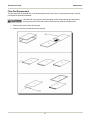
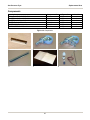
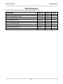
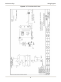
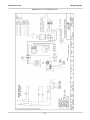
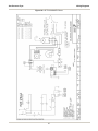
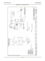
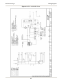
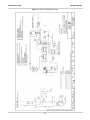
1
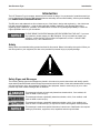
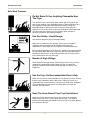
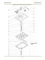
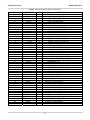
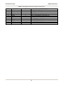
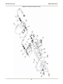
Gas Pressure Fryer
MODELS LGF, LGF-F, & LGF-FC
Service Manual
Serial Numbers 109576 and higher
Warranty Information
LIMITED ONE YEAR WARRANTY
BKI (The “Company”) warrants to the original purchaser/user, that at time of shipment from the Company
factory, this equipment will be free from defect in materials and workmanship. Written notice of a claim
under this Warranty must be given within ONE YEAR AND THREE MONTHS from date of shipment from
the factory. Defective conditions caused by abnormal use or misuse, lack of maintenance, damage by
third parties, alterations by unauthorized personnel, acts of God, failure to follow installation instructions
or any other events beyond the control of the company will NOT be covered under Warranty. The
obligation of the Company under this Warranty shall be limited to repairing or replacing (at the option of
the company) any part which is defective in reasonable opinion of the Company. The user will have the
responsibility and expense of removing and returning the defective part to the Company as well as the
cost of reinstalling the replacement or repaired part.
IN NO EVENT SHALL THE COMPANY BE LIABLE FOR LOSS OF USE, LOSS OF REVENUE OR
LOSS OF PRODUCT OR PROFIT OR FOR INDIRECT OR CONSEQUENTIAL DAMAGES INCLUDING
BUT NOT LIMITED TO, FOOD SPOILAGE OR PRODUCT LOSS. WARRANTY DOES NOT COVER
GLASS BREAKAGE. THE ABOVE WARRANTY IS EXCLUSIVE AND ALL OTHER WARRANTIES,
EXPRESS OR IMPLIED, ARE EXCLUDED INCLUDING THE IMPLIED WARRANTIES OF
MERCHANTABILITY AND FITNESS FOR A PARTICULAR PURPOSE. THIS WARRANTY SHALL
APPLY ONLY WITHIN THE CONTINENTAL UNITED STATES, ITS TERRITORIES, AND
POSSESSIONS AND IN CANADA.
LIMITED NINETY DAY LABOR WARRANTY
All labor necessary to repair or replace factory defective parts will be performed, without charge, to the
end user, by service personnel of a BKI Authorized Distributor during the first ninety days after the date of
installation of the new equipment.
Replacement parts: Any appliance replacement part, except lamps and fuses, which proves to be
defective in material or workmanship within 90 days from date of original installation will be repaired or
replaced without charge F.O.B. Factory, Simpsonville, S.C. or F.O.B. authorized distributor.
The purchaser must post, in a prominent location, instructions to be followed in
the event the user smells gas. This information shall be obtained by consulting
the local gas supplier.
FOR YOUR SAFETY
Do not store or use gasoline or other flammable vapors or liquids in the
vicinity of this or any other appliance.
Improper installation, adjustment, alteration, service or maintenance can
cause property damage, injury or death. Read the installation, operation
and maintenance instructions thoroughly before installing or servicing
this equipment.
Gas Pressure Fryer
Table of Contents
Table of Contents
Table of Contents .................................................................................................................................................... 1
Introduction.............................................................................................................................................................. 2
Safety .................................................................................................................................................................... 2
Safety Signs and Messages ............................................................................................................................. 2
Safe Work Practices ......................................................................................................................................... 3
Safety Labels .................................................................................................................................................... 8
Maintenance ........................................................................................................................................................... 10
Scheduled Maintenance...................................................................................................................................... 10
Safety Pop Valve Procedure........................................................................................................................... 11
Filtering Procedure.......................................................................................................................................... 12
LGF-F and LGF-FC .................................................................................................................................... 12
LGF............................................................................................................................................................. 13
Boil-Out Procedure ......................................................................................................................................... 14
Filter Pad Replacement .................................................................................................................................. 16
Troubleshooting................................................................................................................................................... 17
Replacement Parts ................................................................................................................................................ 18
Assemblies .......................................................................................................................................................... 18
Accessories ......................................................................................................................................................... 41
Components ........................................................................................................................................................ 42
Wiring Diagrams .................................................................................................................................................... 43
Notes....................................................................................................................................................................... 53
1
Gas Pressure Fryer
Introduction
Introduction
The LGF Pressure Fryer is compact, attractive and functional in design. It is constructed of a stainless steel fryer
pot for cleaning ease. Exclusive BKI patented features and safety devices offer flexibility, efficiency and reliability
plus PERFECTION IN PRESSURE FRYING!
The BKI name and trademark on this unit assures you of the finest in design and engineering -- that it has been
built with care and dedication -- using the best materials available. Attention to the operating instructions
regarding proper installation, operation, and maintenance will result in long lasting dependability to insure the
highest profitable return on your investment.
PLEASE READ THIS ENTIRE MANUAL BEFORE OPERATING THE UNIT. If you have
any questions, please contact your BKI Distributor. If they are unable to answer your
questions, contact the BKI Technical Service Department, toll free: 1-800-927-6887.
Outside the U.S., call 1-864-963-3471.
Safety
Always follow recommended safety precautions listed in this manual. Below is the safety alert symbol. When you
see this symbol on your equipment, be alert to the potential for personal injury or property damage.
Safety Signs and Messages
The following Safety signs and messages are placed in this manual to provide instructions and identify specific
areas where potential hazards exist and special precautions should be taken. Know and understand the meaning
of these instructions, signs, and messages. Damage to the equipment, death or serious injury to you or other
persons may result if these messages are not followed.
This message indicates an imminently hazardous situation which, if not avoided, will
result in death or serious injury.
This message indicates a potentially hazardous situation, which, if not avoided, could
result in death or serious injury.
This message indicates a potentially hazardous situation, which, if not avoided, may
result in minor or moderate injury. It may also be used to alert against unsafe practices.
This message is used when special information, instructions or identification are required
relating to procedures, equipment, tools, capacities and other special data.
2
Gas Pressure Fryer
Introduction
Safe Work Practices
Do Not Store Or Use Anything Flammable Near
The Fryer
Your pressure fryer is powered by either natural gas or LP gas. Do not
store or use gasoline or any flammable liquids or vapors near this or any
other appliance. Flammable materials will burn easily. Letting any
flammable liquid or vapor get too close to the fryer could cause an
explosion or fire. Serious injury could result. Examples of flammables that
you should not store near the fryer are gasoline, paint, thinners or
removers, gas tanks, and cleaning materials.
Use Gas Safely-- Avoid Danger
Gas can be a dangerous fuel if not handled safely.
Make sure to ventilate the fryer properly. If the fryer is not properly
ventilated, carbon monoxide can be released around the fryer.
Asphyxiation or suffocation can occur if gas is not ventilated properly.
Before using this appliance for the first time, contact your local gas supplier
for instructions about what to do if you smell gas. Post those instructions
somewhere near the fryer, so that everyone who uses or works near the
fryer knows what to do if they smell gas.
Beware of High Voltage
This equipment uses high voltage. Serious injury can occur if you or any
untrained or unauthorized person installs, services, or repairs this
equipment. Always Use an Authorized Service agent to Service Your
Equipment.
Use the Fryer On Noncombustible Floors Only
Make sure your floor is noncombustible. Do not operate your fryer on floors
that are wood, carpeted or have rubber mats. Placing your fryer on a
combustible floor could cause a fire. Serious injury could result. Examples
of noncombustible floors where you can safely place your fryer are
concrete, tile, and ceramic.
Keep The Area Around Your Fryer Uncluttered
Make sure to keep the area around your fryer clear of any obstacles.
Serious injury can occur if you trip or fall near the fryer. You could be
burned by hot shortening that splashes out of the fryer or by falling against
the hot metal of the fryer.
3
Gas Pressure Fryer
Introduction
Keep The Floor Around Your Fryer Clean Of
Shortening
Make sure to keep the floor around your fryer clean of shortening and
other liquids. Serious injury can occur if you slip near your fryer. You could
be burned by hot shortening that splashes out of the fryer or by falling
against the hot metal of the fryer.
Keep The Lid Closed When The Fryer Is Not In
Use
Hot shortening can splash if someone moves the fryer or bumps into it.
Serious injury can occur if hot shortening splashes out of the fryer.
Do not lean, sit or stand on the fryer or perform any maintenance or
cleaning duties while the fryer or the shortening is hot. You could be
burned.
Keep The Casters Locked
To avoid spilling shortening, keep the casters locked. If any shortening
spills near your fryer, clean it up immediately.
Do Not Overfill The Fryer With Shortening
Hot shortening and steam may escape and burn you if you put too much
shortening in the fryer. Fill the fryer to approximately one inch below the fill
marks that are inside the fryer pot. Heat the shortening. If needed, carefully
add more shortening to bring the level to the fill marks.
Do Not Let Any Water Get Into The Fryer
Always remove excess moisture from food before placing it into the fryer
basket. Water will cause the hot shortening to spatter. You could be
burned.
Do Not Overload The Basket With Food
Hot shortening and steam may escape and burn you if you place too much
food in the basket.
4
Gas Pressure Fryer
Introduction
Always Make Sure The Lid Hook Is Latched When
Closing The Fryer
To make sure the lid hook is latched properly, press down the lid until the
hook snaps shut. Hot shortening and steam can escape if the lid hook is
not latched properly. You could be burned.
Always Tighten The Spin Handle When Closing
The Fryer
Hot shortening and steam can escape if you do not tighten the spin handle
properly. You could be burned. Line up the orange knobs on the fryer lid
handle and the front hook when tightening.
Do Not Over-Tighten The Spin Handle
You could damage the fryer.
Wear Safe Clothing Appropriate To Your Job
Always wear your insulated mitts when handling the fryer basket or touch
any hot metal surfaces. You received a pair of insulated mitts with your
fryer. If you lose or damage your mitts, you can buy new ones at your local
restaurant equipment supply store or from your local BKI Distributor.
Always wear non-skid shoes when working around the fryer or any other
equipment that uses shortening. Never wear loose clothing such as
neckties or scarves while operating your fryer. Keep loose hair tied back or
in a hair net while operating your fryer.
Always wear appropriate personal protection equipment during the filtering
process to guard against possible injury from hot oil.
Always wear appropriate personal protection equipment during the boil-out
process to guard against possible injury from hot cleaning solution.
Never Loosen The Spin Handle Until The
Pressure Gauge Is At Zero
Steam may escape suddenly if you loosen the spin handle before the
gauge is at zero. If steam escapes suddenly, you could be burned.
After the pressure gauge is at zero, wait 5 seconds. Then loosen the spin
handle slowly to open the lid of the fryer. By doing this, the steam will
escape slowly and you will not be burned.
Seal The Safety Valve Properly
To seal the safety valve, lift the arm on the side of the valve. Then release
it. The valve should snap closed. Hot steam can escape from the valve
and you could be burned if you do not seal the valve properly.
5
Gas Pressure Fryer
Introduction
Keep Away From The Vent
Hot steam escapes from the vent continuously when you are using your
fryer. You could be burned if you get too close to the vent.
Keep this manual with the Equipment
This manual is an important part of your equipment. Always keep it near
for easy access.
If you need to replace this manual, contact:
BKI
Technical Services Department
P.O. Box 80400
Simpsonville, S.C. 29680-0400
Or call toll free: 1-800-927-6887
Outside the U.S., call 864-963-3471
Protect Children
Keep children away from this equipment. Children may not understand that
this equipment is dangerous for them and others.
NEVER allow children to play near or operate your equipment.
Keep Safety Labels Clean and in Good Condition
Do not remove or cover any safety labels on your equipment. Keep all
safety labels clean and in good condition. Replace any damaged or
missing safety labels. Refer to the Safety Labels section for illustration and
location of safety labels on this unit.
If you need a new safety label, obtain the number of the specific label
illustrated on page 8, then contact:
BKI
Technical Services Department
P.O. Box 80400
Simpsonville, S.C. 29680-0400
Or call toll free: 1-800-927-6887
Outside the U.S., call 864-963-3471
6
Gas Pressure Fryer
Introduction
Be Prepared for Emergencies
Be prepared for fires, injuries, or other emergencies.
Keep a first aid kit and a fire extinguisher near the equipment. You must
use a 40-pound Type BC fire extinguisher and keep it within 25 feet of your
equipment.
Keep emergency numbers for doctors, ambulance services, hospitals, and
the fire department near your telephone.
Know your responsibilities as an Employer
• Make certain your employees know how to operate the equipment.
• Make certain your employees are aware of the safety precautions on
the equipment and in this manual.
• Make certain that you have thoroughly trained your employees about
operating the equipment safely.
• Make certain the equipment is in proper working condition. If you make
unauthorized modifications to the equipment, you will reduce the
function and safety of the equipment.
Do Not Smoke Near The Fryer.
7
Gas Pressure Fryer
Introduction
Safety Labels
8
Gas Pressure Fryer
Introduction
9
Gas Pressure Fryer
Maintenance
Maintenance
Failure to comply with the maintenance below could result in a serious accident.
Do not over-tighten the spindle assembly. (Only tighten to hold pressure.)
Your fryer will need periodic maintenance and servicing. We strongly suggest that you
use only a service company that is authorized by BKI to do this work.
The restraining device must always be connected when the appliance is in service.
Disconnect for movement, such as servicing or cleaning. Reconnect the restraint when
fryer has been returned to its normal position.
Scheduled Maintenance
Use the following table to help manage scheduled maintenance activities.
FREQUENCY
Each Fry Cycle
Daily
Weekly
Every 6 Months
PERFORMED BY
PART
ACTIVITY
User
Pressure Gauge
Check for proper display of cooking vat
pressure. Contact authorized BKI
service agent if adjustment or
replacement is required.
User
Lid Gasket
Check for unusual wear such as cracks
and deformation, and pressure leaks.
Contact authorized BKI service agent if
adjustment or replacement is required.
User
Dead Weight
Assembly
Clean weight and orifices daily and
check for wear.
User
Filter Pad
Replace filter pad. Refer to the
procedure in this manual.
User
Condensation
Pan
Remove and drain.
User
Filter system
Filter the shortening using the
procedure in this manual.
User
Safety Pop Valve
Check for release of pressure and
proper seal. Refer to the procedure in
this manual.
User
Fryer Pot
Perform the boil-out procedure in this
manual.
Authorized BKI
service agent
Acme Screw and
Nut
Check for wear on the threads.
Authorized BKI
service agent
Solenoid Valve
Check that the valve is holding and
releasing pressure when the timer or
computer activates it.
Authorized BKI
service agent
Hook, Catch,
Spring
Check for wear and ease of operation.
Authorized BKI
service agent
Connections,
Fittings
Check for leakage while oil is pumping.
10
Gas Pressure Fryer
Maintenance
Safety Pop Valve Procedure
The safety pop valve should be blown under pressure periodically to prevent the seat from sticking.
Failure to use the insulated mitts will result in injury. Always use the insulated mitts when
handling the arm on the safety valve.
1. After the pressure is up during a cooking cycle, use the insulated glove to lift the arm on the edge of the
safety valve and let some steam escape. This will clean the valve.
2. Release the lever on the valve, and let it slam shut to seal the valve.
11
Gas Pressure Fryer
Maintenance
Filtering Procedure
Breaded foods require frequent filtering. An excess amount of breading left in the fryer pot will reduce the life of
the shortening. We recommend the shortening be filtered after every three frying cycle loads. When the
shortening starts to show signs of foaming and has a bad taste, do not use it. The fryer pot should be cleaned
before refilling with new shortening. Best results for filtering are obtained while the shortening is hot. You should
filter at the end of every business day. You should also remove and drain the condensation pan daily.
Always wear appropriate personal protection equipment during the filtering process to
guard against possible injury from hot oil.
If the pump motor automatically shuts off while filtering, place the FILTER/OFF/FRY
switch in the OFF position, wait 15 minutes, press the pump motor reset button, then
follow the appropriate refill procedure below.
LGF-F and LGF-FC
1. Set the FILTER/OFF/FRY switch to OFF.
2. Remove the fryer basket.
3. Make certain that the filter pad is clean and not torn.
IMPORTANT: Make certain the vat cover is properly positioned underneath the drain valve. Also
make certain the filter vat and filter screen is under the main drain valve before starting the filtering
process.
4. Move the DRAIN handle slowly to the OPEN position so that the shortening starts to flow evenly. This
is to prevent excessive splashing of hot shortening.
5. When the pot is empty, place the DRAIN handle in the CLOSED position.
To refill the pot automatically, use the steps below:
Hot shortening may splash out of the pot causing severe injury when filling the pot if the
lid is not closed. To prevent shortening splashes, close the lid before filling.
•
Close the lid to prevent shortening splashes.
•
Place the FILL handle to the THRU POT position.
•
Position the FILTER/OFF/FRY switch to FILTER and shortening will automatically pump into the
pot.
•
After 1 minute carefully open the lid to check the level of the shortening.
•
Let the filter continue to pump the shortening until the fill mark in the fryer pot is reached or until
air starts bubbling through the shortening.
•
As soon as air is seen in the shortening, first place the FILL handle to the THRU HOSE position
then position the FILTER/OFF/FRY switch to OFF to prevent shortening degradation and prevent
the filter pump and lines from filling up with shortening.
•
Add new shortening if the fill mark has not been reached.
12
Gas Pressure Fryer
Maintenance
To refill the pot through the rinse hose, use the steps below:
•
Make certain that the rinse hose is connected to rinse hose connector.
•
Holding the hose by the handle, place hose nozzle inside the pot.
Hot shortening may splash out of the pot causing severe injury when filling the pot if the
lid is not held down over the hose nozzle. To prevent shortening splashes, hold the lid
down over the hose nozzle.
•
Hold the lid down over the hose nozzle to prevent shortening splashes.
•
Position the FILL lever in the THRU HOSE position.
•
Position the FILTER/OFF/FRY switch to FILTER and shortening will automatically pump into the
pot.
•
After 1 minute, hold the hose by the handle and carefully raise the lid to check the level of the
shortening.
•
Let the filter continue to pump the shortening until the fill mark in the fryer pot is reached or until
air starts bubbling through the shortening.
•
As soon as air is seen in the shortening, position the FILTER/OFF/FRY switch to OFF to prevent
shortening degradation.
•
Add new shortening if the fill mark has not been reached.
LGF
1. Set the FILTER/OFF/FRY switch to OFF.
2. Remove the fryer basket.
3. Make certain that the FKF filter unit or portable filter unit filter pad is clean and not torn.
4. Position the FKF filter unit or portable filter unit under the main drain valve and make sure it’s filter
screen is in place.
5. Ensure that the FKF filter unit or portable filter unit is powered.
6. Move the DRAIN handle slowly to the OPEN position until the shortening starts to flow evenly. This
will prevent excessive splashing of hot shortening.
7. When the pot is empty, place the DRAIN handle in the CLOSED position.
To refill the pot through the drain valve, use the steps below:
•
Make certain that the braided hose (located on the drain valve) is connected to it’s mating part on
the FKF filter unit or portable filter unit.
Hot shortening may splash out of the pot causing severe injury when filling the pot if the
lid is not closed. To prevent shortening splashes, close the lid before filling.
•
Close the lid to prevent shortening splashes.
13
Gas Pressure Fryer
Maintenance
•
Position the FILTER/OFF/FRY switch to FILTER and shortening will automatically pump into the
pot.
•
After 1 minute carefully open the lid to check the level of the shortening.
•
Let the filter continue to pump the shortening until the fill mark in the fryer pot is reached or until
air starts bubbling through the shortening.
•
As soon as air is seen in the shortening, position the FILTER/OFF/FRY switch to OFF to prevent
shortening degradation and prevent the filter pump and lines from filling up with shortening.
•
Add new shortening if the fill mark has not been reached.
To refill the pot through the rinse hose, use the steps below:
•
Make certain that the rinse hose is connected to it’s mating part on the FKF filter unit or portable
filter unit.
•
Holding the hose by the handle, place hose nozzle inside the pot.
Hot shortening may splash out of the pot causing severe injury when filling the pot if the
lid is not held down over the hose nozzle. To prevent shortening splashes, hold the lid
down over the hose nozzle.
•
Hold the lid down over the hose nozzle to prevent shortening splashes.
•
Position the FILTER/OFF/FRY switch to FILTER and shortening will automatically pump into the
pot.
•
After 1 minute, hold the hose by the handle and carefully raise the lid to check the level of the
shortening.
•
Let the filter continue to pump the shortening until the fill mark in the fryer pot is reached or until
air starts bubbling through the shortening.
•
As soon as air is seen in the shortening, position the FILTER/OFF/FRY switch to OFF to prevent
shortening degradation.
•
Add new shortening if the fill mark has not been reached.
Boil-Out Procedure
Boil-outs remove microscopic particles of carbon that build up on the walls of the fryer pot. To avoid eventual
carbon build-up, off flavors, and shortening breakdown, boil-outs should be done once a week on each fryer
following these procedures.
Always wear appropriate personal protection equipment during the boil-out process to
guard against possible injury from hot cleaning solution.
1. Position the FILTER/OFF/FRY switch to OFF.
2. Drain the clean shortening into an adequate storage container. (Allow the shortening to cool to room
temperature before attempting storage.)
14
Gas Pressure Fryer
Maintenance
3. CLOSE the drain and fill the fryer pot with HOT water to the shortening level fill mark. Do not overfill by
allowing the water level higher than the fill mark.
4. Add ½ cup (4 ounces) of BKI cleaner.
5. Wash down the inside of the pot and lid with the pot brush to loosen the sediment.
6. Set the temperature of the solution as follows:
•
For an LGF or LGF-F – Position the FILTER/OFF/FRY switch to ON. Set the thermostat to a
temperature of 190º F.
•
For an LGF-FC – Position the FILTER/OFF/FRY switch to ON. Press PROG (program), type 1733,
and press ENTER. The fryer pot will heat to a temperature of 190º F during the CLEAN cycle to allow
the CLEAN function to be performed. NOTE: The fryer pot must be below 255º F to enter the CLEAN
mode.
7. Bring the cleaning solution to a rolling boil and maintain the boil for 5 minutes.
8. Place the FILTER/OFF/FRY switch to OFF.
9. Scrub the inside of the fryer pot and inside of the lid again.
10. Before draining the cleaning solution, remove the filter bag, screen and pipe connections from the filter
vat. This must be done before draining the cleaning solution. NEVER pump water or detergent through
the filter system.
11. After 15 minutes, slowly open the drain valve. Drain the solution into the filter vat and discard.
12. Rinse the pot with hot water, using the pot brush to remove remaining sediment, drain and discard.
13. Close the drain and refill the fryer pot with hot water to the proper level.
14. Add approximately 4 to 6 ounces of distilled (white) vinegar to develop a neutralizing solution. Stir the
solution briefly. Leave in the pot for three to five minutes and discard. NOTE: Foaming of shortening
after boil-outs is caused by failure to follow proper neutralizing procedures.
15. Repeat steps 12 through 14 as needed to remove all traces of cleaning solution.
16. Rinse the pot again with Cool water, drain and discard.
Damage to the fryer could result if the fryer pot is not completely dry before filling with
shortening. Refill the fryer pot with shortening ONLY when it is completely dry.
17. Dry the fryer pot, lid, and filter vat COMPLETELY.
18. Close the main drain and fill with new shortening to the proper level.
15
Gas Pressure Fryer
Maintenance
Filter Pad Replacement
The filter pad must be replaced daily. If the shortening has a milky color when it is pumped into the pot, the filter
pad should be replaced immediately.
If the filter pad is not properly closed, breading crumbs will get through the pad opening
and clog the pump. Ensure that the filter pad is properly closed upon replacement.
1. Place the filter screen inside the filter pad.
2. Fold the end of the pad and seal with the bag clip.
16
Gas Pressure Fryer
Maintenance
Troubleshooting
Refer to the table below for troubleshooting information.
Problem
Cause
Possible Solution
Pressure Loss or Not Releasing
Pressure
Dead Weight Valve Leaking
Clean the weight and orifice. If problems
persist, contact an authorized BKI service
agent for corrective action.
Contact an authorized BKI service agent
for corrective action.
After a period of time, it is possible that
the valve seat and/or plunger may stick or
wear. Activate the valve by starting a cook
cycle. You should hear a solid metallic
CLICK sound from the solenoid valve. If
you should hear no sound (or a slow
BUZZING CLICK), contact an authorized
BKI service agent for corrective action.
Contact an authorized BKI service agent
for corrective action.
Contact an authorized BKI service agent
for corrective action.
Contact an authorized BKI service agent
for corrective action.
Press the reset button on end of pump
and hi-limit reset button under control
panel. If problems persist, contact an
authorized BKI service agent for
corrective action.
Tighten the connections. If problems
persist, contact an authorized BKI service
agent for corrective action.
Contact an authorized BKI service agent
for corrective action.
Change filter paper. If problems persist,
contact an authorized BKI service agent
for corrective action.
Check for clogged pump. If problems
persist, contact an authorized BKI service
agent for corrective action.
Contact an authorized BKI service agent
for corrective action.
Make sure drain valve is completely
closed. If problems persist, contact an
authorized BKI service agent for
corrective action.
Press and hold the Toggle/Clear button
while moving the FRY/OFF/FILTER
switch from FRY to OFF and back to
FRY. If problems persist, contact an
authorized BKI service agent for
corrective action.
Lid Gasket Leaking
Solenoid Valve Leaking or
Stuck
Safety Valve not seating
Shortening Heating Too Slowly
Filter System Not Working
Gas pressure is low or isn’t
adjusted properly
Bad thermostat or loose
wires
Uncertain
Connections not tight
Filter valve not open
Filter paper on screen
clogged with crumbs
Motor hums, but does not
pump
Motor and pump coupling
worn
No power to control panel
Computer Hangs
Computer malfunction.
17
Gas Pressure Fryer
Replacement Parts
Replacement Parts
Use the information in this section to identify replacement parts. To order replacement parts, call your local BKI
sales and service representative. Before calling, please note the serial number, model number and voltage on the
rating tag affixed to the unit.
Assemblies
Description
Assembly #
Figure #
Table #
LID/ARM ASSEMBLY
AN3211350S
Figure 1
Table 1
DEAD WEIGHT & PRESSURE GAUGE ASSEMBLY
N/A
Figure 2
Table 2
DRAIN/MOTOR/PIPING ASSEMBLY
N/A
Figure 3
Table 3
GAS BURNER TRAY ASSEMBLY (LP)
GAS BURNER TRAY ASSEMBLY (NATURAL)
SB3467
SB3466
Figure 4
Table 4
CONTROL/INSULATION PANEL LGF 220/60/1
CONTROL/INSULATION PANEL LGF-F 110/220/50/1
CONTROL/INSULATION PANEL LGF-F 220/380/50/1
CONTROL/INSULATION PANEL LGF-F 220/60/1
CONTROL/INSULATION PANEL LGF-F 240V
CONTROL/INSULATION PANEL LGF-F
SB3489
SB3493
SB3337B
SB3495
SB3458
SB3326A
Figure 5
Table 5
CONTROL/INSULATION PANEL LGF-FC
CONTROL/INSULATION PANEL LGF-FC 240V ENG
CONTROL/INSULATION PANEL LGF-FC ARGENTINA
CONTROL/INSULATION PANEL LGF-FC KOREA
SB3483
SB3457
SB3483B
SB3483A
Figure 6
Table 6
DOOR ASSEMBLY W/POCKET
SB3290
Figure 7
Table 7
OIL VAT ASSEMBLY
AN32112800
Figure 8
Table 8
OUTLET BOX ASSY, LGF
OUTLET BOX ASSY, LGF-F
SB3342
SB3343
Figure 9
Table 9
SOLENOID VALVE 120V
SOLENOID VALVE 240V
SB3344
SB3335
Figure 10
QUICK DISCONNECT ASSEMBLY
SB1997S
Figure 11
Table 11
DRAIN VALVE & PLUGS
SB1999S
Figure 12
Table 12
18
Table 10
Gas Pressure Fryer
Replacement Parts
Figure 1. Lid/Arm Assembly, AN3211350S (Sheet 1 of 4)
19
Gas Pressure Fryer
Replacement Parts
Figure 1. Lid/Arm Assembly, AN3211350S (Sheet 2 of 4)
20
Gas Pressure Fryer
Replacement Parts
Figure 1. Lid/Arm Assembly, AN3211350S (Sheet 3 of 4)
21
Gas Pressure Fryer
Replacement Parts
Figure 1. Lid/Arm Assembly, AN3211350S (Sheet 4 of 4)
22
Gas Pressure Fryer
Replacement Parts
Table 1. Lid/Arm Assembly (AN3211350S) Parts
ITEM #
PART #
Figure 1 (sheet 1)
AN3211350S
Figure 1 (sheet 2)
H0157
1
FT0332
2
K0003
3
K0020
4
K0043
Figure 1 (sheet 3)
AB19103900
1
A0120
2
H0155
3
P0094
4
H0024
5
K0043
6
N0160
7
NUT128
8
S0091
9
SCR122
10
SCR259
11
TB0020
12
H0156
13
WSH045
14
WSH102
15
FT0407
16
F0026
Figure 1 (sheet 4)
SB3492
1
B0857*
2
C0464*
3
D0054
4
F0286
5
FKMA199
6
G0033
7
G0093*
8
S0045
9
SCR176
10
WLGFA107
11
F0107
12
FKMA016
13
FKMA152
14
FT0049
15
LGFA134*
16
LZ0107
17
N0153
18
N0345
19
SB3264
20
SCR151
21
SCR178
22
TB0021*
23
TC0003
24
TC0005*
25
TS0010*
26
S0071
* - Part of Cast Lid Assembly SB3491S.
QTY
1
3
2
1
1
1
1
1
1
1
1
1
2
1
2
2
1
2
2
2
1
1
1
1
1
1
1
1
1
1
1
9
1
1
1
1
2
1
1
1
1
1
4
1
1
1
1
1
1
DESCRIPTION
LID/ARM ASSY
HANDLE, SPIN FOR FRYERS
STUD, 5.5” TIGHTEN DN HN
KNOB, BLACK #85C
HUB, TIGHTEN DOWN
KNOB, ORANGE
ARM ASSY, LGF
ARM COMPLETE FKM LGF
HANDLE, BLK DELRIN FKM LPF LGF
PIN, HOOK FKM, LPF, LGF
HOOK, LID 1018 ALLOY
KNOB, ORANGE
DECAL, WARNING BEFORE USING
NUT, 5/16-18 SS 18-8 CAP
SPRING, HOOK LGF LPF FKM
SCREW, 1/4-20 X 1/2 FLAT HD
SCREW, 1/4-20 X 1/2 PHIL RD HD
BUSHING, BRONZE 1"
HANDLE SIDE FOR H0155 FKM LPF LGF
WASHER, 5/16 LOCK ZINC PLTD
WASHER, 1/4 INT LOCK
PLUG, HOLE 3/8" SHORT PRONG
ROLL PIN, 5/32 X 3/4
LID LOCKING ASSY, LGF DOVE TAIL
BUSHING, BRONZE 3/8X9/16X5/8
CASTING, LGF TOP W/DOVETAIL ALAMAG35
DIAPHRAGM, LGF
PIN, LOCKING .810 X 2.25
RETAINER, DIAPHRAGM FKM
GUARD, DIAPHRAGM
GASKET, SQ SILICONE BONDED LGF
SPRING, LOCKING PIN 1.85 OAL
SCREW, 8-32 X 3/8 SLOT BINDING
CONDENSATE DRAIN WELDMENT
LOCK KEY PIN, FRYERS
PIN, HINGE
KEY, TIGHTEN DOWN SCREW
COLLAR, 1/2" SET BRIGHT
TIGHTEN DOWN PLATE, LGF
PLATE, LID FOR LOCKING DEVICE
DECAL, FKM WARNING ACME SCREW
DECAL, HOOK LID INSTRUCTIONS
CAST LID COVER WELD. LGF
SCREW, 10-32 X 3/4 SOC HD CAP
SCREW, 5/16-18 X 1 FLAT HD
TIGHTEN DOWN BASE COLD ROLLED
COLLAR, THREADED SHAFT
COLLAR, LOCKING RING
SCREW, TIGHTEN DOWN
SPRING, TORSION
23
Gas Pressure Fryer
Replacement Parts
Figure 2. Dead Weight & Pressure Gauge Assembly
24
Gas Pressure Fryer
Replacement Parts
Table 2. Dead Weight & Pressure Gauge Assembly Parts
ITEM #
1
2
3
4
5
6
7
8
9
10
11
PART #
C0657
W0201
O0001
FT0414
B0965
FT0232
FT0234
FT0190
FT0084
G0064
O0002
QTY
1
1
1
1
1
1
1
1
1
1
1
DESCRIPTION
COVER, DEAD WEIGHT VALVE FKM
WEIGHT, VALVE FKM 12#
ORIFICE, SS
NIPPLE, 1/2 X 3 3/4 SS SCH 80
BODY, DEAD WEIGHT VALVE LGF SS
NIPPLE, 1/2 X 2 SS 304
NIPPLE, 1/4 X 1 1/2 SS 304
ELL, STREET 1/4 90 DEG CP
COUPLING, BRASS 1/4
GAUGE, PRESSURE 30 PSI
GASKET, O-RING #2-222
25
Gas Pressure Fryer
Replacement Parts
Figure 3. Drain/Motor/Piping Assembly
26
Gas Pressure Fryer
Replacement Parts
Table 3. Drain/Motor/Piping Assembly Parts
ITEM #
1
2
3
3a
4
5
6
7
8
9
10
11
12
13
14
15
16
17
18
19
20
21
22
23
24
25
26
27
28
29
30
31
PART #
TU0205
FT0536
M0053
P0070
FT0538
FT0507
FT0412
SB1314
FT0051
FT0044
MB19101000
LGFA322
F0255
SP0014
F0254
F0253
SP0034
FT0543
NUT253
LGFA240
S0054
WLGFA348
N0270
SCR326
H0216
C0672
LGFA192
C0668
P0081
B0851
LGFA212
SCR016
QTY
2
3
1
1
1
1
1
1
1
2
1
1
1
2
2
1
2
1
2
1
1
1
1
2
1
1
1
1
1
1
1
2
DESCRIPTION
TUBING, 12" 1/2" ID
COUPLING, 5/8 45¦ FLARE TO
MOTOR, LEESON LESS CORD/PUMP
PUMP ONLY FOR HAIGHT MOTOR
TEE, 1/2 X 1/2 X 3/8 BLK
CONNECTOR, MALE 10FBU-S NKL PLTD
NIPPLE, 3/8 NPT X 1 1/2 SCH 40
BALL VALVE ASSY, FRYERS
NIPPLE, 3/8 X C BLK
ELL, STREET 3/8 90 DEG BLACK
DRAIN VALVE
DRAIN VALVE EXTENSION
PIN, CLEVIS 3/16 X 1-1/4
SPACER, ALUM 0.50 X 0.125
PIN, COTTER HAIRPIN #213
PIN, CLEVIS 3/16 X 1-3/4
SPACER, DRAIN VALVE BRKT
DRAIN VALVE BRACKET, FRYERS
NUT, 6-32 S/S 18-8 NYLON
COVER, MICROSWITCH
SWITCH, MICRO BZ-2RW822-A2
HANDLE PLATE WELD
DECAL, DRAIN SUPPORT PLATE LGF
SCREW, 6-32 X 1-3/4 SLTD RD HD
HANDLE, DRAIN VALVE
COVER, DRAIN HANDLE RED
HANDLE, FILL VALVE
COVER, FILL HANDLE BLACK
PLUG, F-H4F4-7-7 QUIK DISCONN
BUSHING, BLK HEX REDUCING
TUBING, TEE TO DISCONNECT
SCREW, 10 X 1/2 SLTD HEX WSHR
27
Gas Pressure Fryer
Replacement Parts
Figure 4. Burner Tray Assembly
28
Gas Pressure Fryer
Replacement Parts
Table 4. Burner Tray Assembly Parts
ITEM #
1
2
3
4
5
6
7
8
9
10
1
2
3
4
5
6
7
8
9
10
PART #
SB3467
C0724
O0011
C0727
FT0399
GB0004
I0015
LGFA233
LGFA323
ML0064
SB3346
LGFA052
MN0001
SB3468
SB3466
C0724
O0023
C0726
FT0399
GB0004
I0015
LGFA233
LGFA323
ML0064
SB3330
LGFA053
MN0001
SB3468
QTY
1
1
1
1
3
2
0.083
1
1
1
1
2
1
1
1
1
5
1
3
2
0.083
1
1
1
1
2
1
1
DESCRIPTION
LP GAS BURNER TRAY ASSEMBLY
GAS CONTROL PILOT BURNER
ORIFICE, ASSY BBR12 (LGF)
GAS CONTROL, STEP OPEN LP
ELL, STREET 1/2" 90 BRASS
BURNER, GAS BRAY LGF
INSULATION, BOARD 7/16
BURNER TRAY FRONT W/SLOT
PILOT BRKT, HOT SURFACE IGNITION
S/S TUBING 304 1/4 DIA CORRUG.18"
MANIFOLD ASSY, LGF LP NO DWG
BURNER ORIFICE, LP O0005
MANIFOLD, GAS SUPPLY
BURNER TRAY, REAR WELD LGF
NATURAL GAS BURNER TRAY ASSEMBLY
GAS CONTROL PILOT BURNER
ORIFICE, PILOT BURNER NAT (LGF)
GAS CONTROL, STEP OPEN NATURAL
ELL, STREET 1/2" 90 BRASS
BURNER, GAS BRAY LGF
INSULATION, BOARD 7/16
BURNER TRAY FRONT W/SLOT
PILOT BRKT, HOT SURFACE IGNITION
S/S TUBING 304 1/4 DIA CORRUG.18"
MANIFOLD ASSY, LGF NAT
BURNER ORIFICE, NATURAL O0005
MANIFOLD, GAS SUPPLY
BURNER TRAY, REAR WELD LGF
29
Gas Pressure Fryer
Replacement Parts
Figure 5. Control/Insulation Panel LGF & LGF-F
30
Gas Pressure Fryer
Replacement Parts
Table 5. Control/Insulation Panel LGF & LGF-F Parts
ITEM #
1
2
3
4
5
6
7
8
9
10
PART #
B1050
F0097
FH0001
K0030
N0267
S0104
T0022
T0024
TI0011
TI0012
TI0019
TF0030
TF0005
QTY
1
1
1
1
1
2
1
1
1
1
DESCRIPTION
BEZEL, ROBERTSHAW THERMOSTAT
FUSE, 15A 300V SC15 TIME DELAY
FUSE HOLDER, 15A 300V HPF-EE
KNOB, T-STAT BLK 400DEG
DECAL, CONTROL PANEL LGF
SWITCH, RKR DPDT 15A 250V LAMP
THERMOSTAT, 375 DEG SGL POLE
THERMOSTAT, HI LIMIT 425 DEG
TIMER, 30 MIN 208/240/60
TIMER, 30 MIN 120V
TIMER, 36 MIN 240V 50 CYCLE
TRANSFORMER, 240-24V LGF
TRANSFORMER, 120-24V LGF
31
Gas Pressure Fryer
Replacement Parts
Figure 6. Control/Insulation Panel LGF -FC
32
Gas Pressure Fryer
Replacement Parts
Table 6. Control/Insulation Panel LGF -FC Parts
ITEM #
1
2
3
4
5
6
7
8
9
10
PART #
CP0039
N0404
R0044
S0104
T0024
W0053
W0054
TF0030
TF0005
F0097
FH0001
FN0013
FN0014
QTY
1
1
2
1
1
1
1
1
1
1
DESCRIPTION
CONTROLLER, VFD LESS HARNESS
DECAL, CONTROL LGFFC COMPUTER
RELAY, X-40, SGL FRYER
SWITCH, RKR DPDT 15A 250V LAMP
THERMOSTAT, HI LIMIT 425 DEG
TRANSFORMER ASSY, 120V
TRANSFORMER ASSY 240V
TRANSFORMER, 240-24V LGF
TRANSFORMER, 120-24V LGF
FUSE, 15A 300V SC15 TIME DELAY
FUSE HOLDER, 15A 300V HPF-EE
FAN, 115V NMB 3115FS12WB30
FAN, 230V NMB 3115FS23WB30
33
Gas Pressure Fryer
Replacement Parts
Figure 7. Door Assembly W/Pocket (SB3290)
34
Gas Pressure Fryer
Replacement Parts
Table 7. Door Assembly W/Pocket (SB3290) Parts
ITEM #
1
2
3
4
5
6
7
8
9
10
11
12
13
14
15
16
17
18
PART #
H0010
N0059
N0165
N0169
N0527
N0175
N0176
N0181
N0319
N0346
N0350
P0022
RIV172
SB3289
SCR008
WLPFA096
N0153
H0009
QTY
2
1
1
1
1
1
1
1
1
1
1
1
4
1
6
1
1
1
DESCRIPTION
HINGE, DOOR, LH, PIN SIDE FRY.DOORS
DECAL, SMALL BRUSH/
DECAL, NOTICE LOST MANUAL
DECAL, MANUAL GAS SHUT OFF
DECAL, SAFETY INSTR FRYERS
DECAL, SLIPPING ADMONITIONS
DECAL, INSTR & SAFETY MANUAL
DECAL, USE ONLY ON NON-COMBUST
DECAL, RESTRAIN DEVICE FR/CAN
DECAL, LGF RESTRAINING WARNING
DECAL, GAS WARNING LGF
HANDLE, PULL SS P60-1010
RIVET, 1/8 X 1/4 CS PLT POP
LGF INSIDE DOOR WELDMENT
SCREW, 10 X 1/2 PHIL TRUSS HD
DOOR, LPF CORNERS WELDED
DECAL, FKM WARNING ACME SCREW
HINGE, DOOR, RH, PIN SIDE FRY.DOORS
35
Gas Pressure Fryer
Replacement Parts
Figure 8. Oil Vat Assembly (AN32112800)
36
Gas Pressure Fryer
Replacement Parts
Table 8. Oil Vat Assembly (AN32112800) Parts
ITEM #
1
2
3
4
5
6
7
8
9
10
11
12
PART #
AN86208400
SB1991
O0013
WB86202700
SB7659
FS0003
FS0002
FS0001
FC0004
WB32112600
FB32112702
N0395
SB2306
QTY
1
1
1
1
1
1
1
1
1
1
1
1
1
DESCRIPTION
FILTER SCREEN ASSY, LGF
QUIK DISCONNECT BRACKET WELDMENT
O-RING, FLUOROCARBON V680-70
FILTER TUBING/DISCONN ALF LGF LPF
FILTER SCREEN FITTING SPOTWELD
FILTER SCREEN, TOP
FILTER SCREEN, INTERCEPTOR
FILTER SCREEN, BOTTOM
NUT SCREEN RETAINING FKM-F &
FILTER VAT WELD ALF LPF LGF
COVER, FILTER VAT LGF
DECAL, VAT COVER SAFETY WARN
S/S CRUMB BASKET WELD, FKF
Figure 9. Outlet Box Assembly
Table 9. Outlet Box Assembly Parts
ITEM #
1
2
3
4
5
6
7
PART #
F0067
F0111
FT0153
FT0206
FT0359
OB0004
C0652
QTY
4
1
1
1
1
1
1
DESCRIPTION
WASHER, REDUCER #100-50
TERMINAL GROUNDING LUG
CONNECTOR, BOX 3/8 X 90
CONNECTOR, 1/2" 1002DC
ELL, 1/2 90 SHORT
BOX, OUTLET 4 11/16 SQ
COVER, #72C-1 FOR OB0004 (not shown)
37
Gas Pressure Fryer
Replacement Parts
Figure 10. Solenoid Valve Assembly
Table 10. Solenoid Valve Assembly Parts
ITEM #
1
2
3
4
5
6
7
8
9
10
11
PART #
FT0235
FT0198
SV0004
FT0413
FT0414
FT0067
PV0001
LGFA228
FT0398
FT0404
FT0358
QTY
3
1
1
1
1
1
1
1
1
1
1
DESCRIPTION
NIPPLE, 1/2 X C SS
TEE, BRASS 1/2" CP
VALVE, SOLENOID HV-214-761-2 120V
NIPPLE, 1/2 X 1 3/4 SS
NIPPLE, 1/2 X 3 3/4 SS
BUSHING, C110JO 3/4 X 1/2 CP
VALVE, POP SAFETY
CONDUIT 1/2" EMT 20.062"
REDUCING COUPLING
ELL, 1/2" STREET CHROME PLTD
CONNECTOR COMPRESSION 1/2"
38
Gas Pressure Fryer
Replacement Parts
Figure 11. Quick Disconnect Assembly (SB1997S)
Table 11. Quick Disconnect Assembly (SB1997S) Parts
ITEM #
1
2
3
4
5
6
7
8
PART #
B0996
FT0429
FT0500
FT0536*
O0013
O0014
S0138
SCR4531*
QTY
1
1
1
1
2
1
1
2
DESCRIPTION
BALL, 11/16" STEEL BEARING
QUICK DISCONNECT, PUMP SIDE
QUICK DISCONNECT, VAT SIDE
COUPLING, 5/8 45¦ FLARE TO
O-RING, FLUOROCARBON V680-70
O-RING, PARKER #2-124 LARGE
SPRING, FOR QUICK DISCONNECT
SCREW, #10 24X3/8" WASHERED
* - Not included with SB1997S
39
Gas Pressure Fryer
Replacement Parts
Figure 12. Drain Valve & Plugs (SB1999S)
Table 12. Drain Valve & Plugs (SB1999S) Parts
ITEM #
1
2
PART #
MB19101000
FT0243
QTY
1
2
DESCRIPTION
DRAIN VALVE REPLACEMENT
PLUG, 3/8" SQ HEAD PIPE
40
Gas Pressure Fryer
Replacement Parts
Accessories
Description
BASKET, LGF
HANDLE, TEE STYLE LIFT
BRUSH, DRAIN (LONG WHITE)
BRUSH, LONG #5702
BRUSH, POT SCRUBBER, WHITE
BRUSH, SHORT #6175
RESTRAINT
HOSE 72” GAS
INSULATED MITT 13"
Accessory #
B0108B
H0151
B0075
B0051
B0049
B0052
FT0279
H0048
G0052
Figure #
Figure 13
Figure 13
Figure 13
Figure 13
Figure 13
Figure 13
Figure 13
Figure 13
Figure 13
Figure 13. Accessories
1
2
3
4
5
6
7
8
9
41
Item #
1
2
3
4
5
6
7
8
9
Gas Pressure Fryer
Replacement Parts
Components
Description
ARM ADJUSTABLE STOP /FKM
CASTER, 2470-DIK-075-R05/22
CASTER, 2477-DIK-075-R05/22
FILTER BAG CLIP FI0007
FILTER, FKM-F 13.5 X 20.5
THERMISTER PROBE, 6.85 X 1
Component #
A0101
C0409
C0410
ST0015
FI0007
T0047
Figure #
Figure 14
Figure 14
Figure 14
Figure 14
Figure 14
Figure 14
Figure 14. Components
1
2
3
4
5
6
42
Item #
1
2
3
4
5
6
Gas Pressure Fryer
Wiring Diagrams
Wiring Diagrams
Refer to the table below to find the wiring diagram associated with your unit.
Wiring Diagram
Diagram #
Figure #
Page #
LGF-F 120V/60HZ/1 Phase
LGFE1033
Figure 15
44
LGF-F 220V/240V/50HZ/1 Phase
LGFE1045
Figure 16
45
LGF-F 220V/50HZ/1 Phase
LGFE1046
Figure 17
46
LGF-F 220V/60HZ/1 Phase
LGFE1047
Figure 18
47
LGF-F 240V/50HZ/1 Phase
LGFE1035
Figure 19
48
LGF-FC 120V/60HZ/1 Phase
LGFE1034
Figure 20
49
LGF-FC 220V/50HZ/1 Phase
LGFE1038
Figure 21
50
LGF-FC 220V/60HZ/1 Phase
LGFE1041
Figure 22
51
LGF-FC 240V/50HZ/1 Phase
LGFE1036
Figure 23
52
43
Gas Pressure Fryer
Wiring Diagrams
Figure 15. LGF-F 120V/60HZ/1 Phase
44
Gas Pressure Fryer
Wiring Diagrams
Figure 16. LGF-F 220V/240V/50HZ/1 Phase
45
Gas Pressure Fryer
Wiring Diagrams
Figure 17. LGF-F 220V/50HZ/1 Phase
46
Gas Pressure Fryer
Wiring Diagrams
Figure 18. LGF-F 220V/60HZ/1 Phase
47
Gas Pressure Fryer
Wiring Diagrams
Figure 19. LGF-F 240V/50HZ/1 Phase
48
Gas Pressure Fryer
Wiring Diagrams
Figure 20. LGF-FC 120V/60HZ/1 Phase
49
Gas Pressure Fryer
Wiring Diagrams
Figure 21. LGF-FC 220V/50HZ/1 Phase
50
Gas Pressure Fryer
Wiring Diagrams
Figure 22. LGF-FC 220V/60HZ/1 Phase
51
Gas Pressure Fryer
Wiring Diagrams
Figure 23. LGF-FC 240V/50HZ/1 Phase
52
Gas Pressure Fryer
Notes
Notes
53
P.O. Box 80400, Simpsonville, S.C. 29680-0400, USA
http://www.bkideas.com
Made and printed in the U.S.A
LI0196/0205