1
INVERTER
INVERTER
Plug-in option
INVERTER
PRE-OPERATION INSTRUCTIONS
1
INSTALLATION
2
WIRING
3
FR-A7NS
INSTRUCTION MANUAL
SSCNET III communication function
SSCNET III COMMUNICATION
STATUS
INVERTER SETTING AND
DISPLAY
FR-A7NS
RESTRICTIONS ON THE
FUNCTIONS
HEAD OFFICE: TOKYO BUILDING 2-7-3, MARUNOUCHI, CHIYODA-KU, TOKYO 100-8310, JAPAN
Printed in Japan
Specifications subject to change without notice.
INSTRUCTION MANUAL
IB(NA)-0600308ENG-C(1110) MEE
C
PRECAUTIONS
ALARM INDICATION DEFINITIONS
AND CORRECTIVE ACTIONS
TROUBLESHOOTING
4
5
6
7
8
9
Thank you for choosing this Mitsubishi Inverter plug-in option.
This instruction manual gives handling information and
precautions for use of this equipment. Incorrect handling might
cause an unexpected fault. Before using the equipment, please
read this manual carefully to use the equipment to its optimum.
Please forward this manual to the end user.
This section is specifically about
safety matters
Do not attempt to install, operate, maintain or inspect this
product until you have read through this instruction manual and
appended documents carefully and can use the equipment
correctly. Do not use this product until you have a full
knowledge of the equipment, safety information and
instructions.
In this instruction manual, the safety instruction levels are
classified into "WARNING" and "CAUTION".
WARNING
CAUTION
Assumes that incorrect handling may
cause hazardous conditions, resulting
in death or severe injury.
Assumes that incorrect handling may
cause hazardous conditions, resulting
in medium or slight injury, or may
cause physical damage only.
CAUTION level may lead to a serious
Note that even the
consequence according to conditions. Please follow the
instructions of both levels because they are important to
personnel safety.
SAFETY INSTRUCTIONS
1. Electric Shock Prevention
WARNING
• While power is on or when the inverter is running, do not
open the front cover. You may get an electric shock.
• Do not run the inverter with the front cover or wiring cover
removed. Otherwise, you may access the exposed highvoltage terminals and charging part and get an electric shock.
• If power is off, do not remove the front cover except for wiring
or periodic inspection. You may access the charged inverter
circuits and get an electric shock.
• Before starting wiring or inspection, check to make sure that
the indication of the inverter operation panel is off, wait for at
least 10 minutes after the power supply has been switched off,
and check that there are no residual voltage using a tester or
the like. The capacitor is charged with high voltage for some
time after power off and it is dangerous.
• Any person who is involved in the wiring or inspection of this
equipment should be fully competent to do the work.
• Always install the plug-in option before wiring. Otherwise,
you may get an electric shock or be injured.
• Do not touch the plug-in option with wet hands. Otherwise
you may get an electric shock.
• Do not subject the cables to scratches, excessive stress,
heavy loads or pinching. Otherwise you may get an electric
shock.
A-1
2. Injury Prevention
3) Usage
WARNING
CAUTION
• Apply only the voltage specified in the instruction manual to
each terminal. Otherwise, burst, damage, etc. may occur.
• Ensure that the cables are connected to the correct terminals.
Otherwise, burst, damage, etc. may occur.
• Always make sure that polarity is correct to prevent damage, etc.
Otherwise, burst, damage may occur.
• While power is on or for some time after power-off, do not touch
the inverter as it is hot and you may get burnt.
3. Additional Instructions
Also note the following points to prevent an accidental failure,
injury, electric shock, etc.
1) Transportation and mounting
CAUTION
• Do not install or operate the plug-in option if it is damaged or
has parts missing.
• Do not stand or rest heavy objects on the product.
• Check that the mounting orientation is correct.
• Prevent other conductive bodies such as screws and metal
fragments or other flammable substance such as oil from
entering the inverter.
2) Trial run
CAUTION
• When parameter clear or all parameter clear is performed,
reset the required parameters before starting operations.
Each parameter returns to the initial value.
• For prevention of damage due to static electricity, touch
nearby metal before touching this product to eliminate static
electricity from your body.
4) Maintenance, inspection and parts replacement
CAUTION
• Do not test the equipment with a megger (measure insulation
resistance).
5) Disposal
CAUTION
• Treat as industrial waste.
CAUTION
• Before starting operation, confirm and adjust the parameters.
A failure to do so may cause some machines to make
unexpected motions.
A-2
• Do not modify the equipment.
• Do not perform parts removal which is not instructed in this
manual. Doing so may lead to fault or damage of the inverter.
6) General instruction
All illustrations given in this manual may have been drawn with
covers or safety guards removed to provide in-depth
description. Before starting operation of the product, always
return the covers and guards into original positions as specified
and operate the equipment in accordance with the manual.
⎯ CONTENTS ⎯
1
PRE-OPERATION INSTRUCTIONS
1
1.1
Inverter Type ......................................................................................................................................1
1.2
Unpacking and Product Confirmation .............................................................................................2
1.2.1
1.2.2
Packing confirmation ...................................................................................................................................... 7
Parts ............................................................................................................................................................... 8
1.3
Caution................................................................................................................................................9
1.4
Operation Overview .........................................................................................................................10
2
INSTALLATION
12
2.1
Pre-Installation Instructions ...........................................................................................................12
2.2
Shaft number Setting.......................................................................................................................13
2.3
Installation Procedure .....................................................................................................................14
3
WIRING
16
3.1
System configuration (when FR-A7AP is used)............................................................................16
3.2
Wiring example (when FR-A7AP is used)......................................................................................18
3.3
SSCNET III cable ..............................................................................................................................20
3.3.1
3.4
4
SSCNET III cable laying ...............................................................................................................................24
Wiring................................................................................................................................................26
SSCNET III COMMUNICATION STATUS
32
I
5
INVERTER SETTING AND DISPLAY
35
5.1
Parameter List ..................................................................................................................................35
5.2
Operation Mode Setting ..................................................................................................................36
5.2.1
5.2.2
5.3
Operation mode indication............................................................................................................................ 36
Operation mode switchover method............................................................................................................. 37
Operation at Communication Error Occurrence...........................................................................40
5.3.1
Alarm and measures .................................................................................................................................... 40
5.4
Inverter Reset ...................................................................................................................................41
5.5
Setting SSCNET III communication function ................................................................................42
5.5.1
5.5.2
5.5.3
5.5.4
5.5.5
5.5.6
6
Pr.499 SSCNET III operation selection ........................................................................................................ 42
Pr.379 SSCNET III rotation direction selection............................................................................................. 47
Pr.449 SSCNET III input filter setting ........................................................................................................... 48
Pr.52 DU/PU main display data selection..................................................................................................... 48
Pr.185 JOG terminal function selection ........................................................................................................ 49
Pr.800 Control method selection .................................................................................................................. 49
RESTRICTIONS ON THE FUNCTIONS
50
6.1
Function Restriction List.................................................................................................................50
6.2
Inverter Parameter List....................................................................................................................53
6.3
Inverter I/O Terminal Function List ................................................................................................69
6.3.1
6.3.2
II
Input terminal function .................................................................................................................................. 69
Output terminal function ...............................................................................................................................72
7
PRECAUTIONS
74
8
ALARM INDICATION DEFINITIONS AND CORRECTIVE ACTIONS
75
9
TROUBLESHOOTING
79
III
1
PRE-OPERATION INSTRUCTIONS
1.1
Inverter Type
The inverter type, 55K and 75K stated in this Instruction Manual differs according to each -NA, -EC, -CH(T)
versions. Refer to the following correspondence table for each inverter type. (Refer to the instruction manual
of each inverter for the inverter type.)
For example, "for the 75K or more" indicates "for the FR-A740-01440-NA or more" in the case of FR-A740
of NA version.
NA
A700
FR-A720-55K
FR-A720-75K
FR-A740-55K
FR-A740-75K
FR-A720-02150-NA
FR-A720-02880-NA
FR-A740-01100-NA
FR-A740-01440-NA
EC
⎯
⎯
FR-A740-01800-EC
FR-A740-02160-EC
CH
⎯
⎯
FR-A740-55K-CHT
FR-A740-75K-CHT
1
1
PRE-OPERATION INSTRUCTIONS
1.2
Unpacking and Product Confirmation
Take the plug-in option out of the package, check the unit name, and confirm that the product is as you
ordered and intact.
This product is a plug-in option for the FR-A700 series inverter assembled in and after January 2007.
Refer to the table below to check the SERIAL (Serial No.) indicated on the inverter rating plate or package.
(1) NA specification
z200V class
Inverter Type
Label on
Product
Package
Identification
Symbol
FR-A720-00030-NA
FR-A720-00050-NA
Without
FR-A720-00080/
00110-NA
FR-A720-00175-NA
2
Without
<G>
Without
<G>
Lower Third
SERIAL
and Second
(Upper
Number of
Three
TC Number
Numbers of
on Rating
SERIAL)
Plate
Q71
G5
P71
G5
G7
G5
G7
Q71
D71
R71
D71
Inverter Type
FR-A720-00240/
00330-NA
FR-A720-00460-NA
FR-A720-00610 to
00900-NA
FR-A720-01150 to
01750-NA
FR-A720-02150-NA
FR-A720-02880/
03460-NA
Label on
Product
Package
Identification
Symbol
Lower Third
SERIAL
and Second
(Upper
Number of
Three
TC Number
Numbers of
on Rating
SERIAL)
Plate
Q71
P71
R71
Without
G5
Q71
P71
M71
PRE-OPERATION INSTRUCTIONS
z400V class
Inverter Type
FR-A740-00015 to
00310-NA
FR-A740-00380/
00440-NA
FR-A740-00570 to
00860-NA
FR-A740-01100-NA
FR-A740-01440
to 02660-NA
FR-A740-03250-NA
FR-A740-03610-NA
FR-A740-04320/
04810-NA
FR-A740-05470-NA
Label on
Product
Package
Identification
Symbol
Without
<G>
Without
<G>
Without
<G>
Without
<G>
Without
<G>
Without
<G>
Without
<G>
Without
<G>
Without
<G>
Lower Third
SERIAL
and Second
(Upper
Number of
Three
TC Number
Numbers of
on Rating
SERIAL)
Plate
G5
Q71
G7
E71
G5
Q71
G7
F71
G5
P71
G7
E71
G5
P71
G7
D71
G5
M71
G7
E71
G5
N71
G7
F71
G5
M71
G7
F71
G5
M71
G7
E71
G5
N71
G7
E71
Inverter Type
FR-A740-06100-NA
FR-A740-06830-NA
FR-A740-07700/
08600-NA
FR-A740-09620-NA
Label on
Product
Package
Identification
Symbol
Without
<G>
Without
<G>
Without
<G>
Without
<G>
Lower Third
SERIAL
and Second
(Upper
Number of
Three
TC Number
Numbers of
on Rating
SERIAL)
Plate
G5
M71
G7
D71
G5
J71
G7
D71
G5
M71
G7
D71
G5
N71
G7
D71
3
1
PRE-OPERATION INSTRUCTIONS
(2) EC specification
Inverter Type
FR-A740-00023 to
00126-EC
FR-A740-00170/
00250-EC
Label on
Product
Package
Identification
Symbol
Without
<G>
Without
<G>
Lower Third
SERIAL
and Second
(Upper
Number of
Three
TC Number
Numbers of
on Rating
SERIAL)
Plate
G5 or G6
M71
G7 or G8
F71
G5 or G6
N71
G7 or G8
F71
Inverter Type
FR-A740-00310/
00380-EC
FR-A740-00470/
00620-EC
FR-A740-00770 to
12120-EC*
Lower Third
SERIAL
and Second
(Upper
Number of
Three
TC Number
Numbers of
on Rating
SERIAL)
Plate
G5 or G6
M71
G7 or G8
F71
G5
N71
G7
G71
Label on
Product
Package
Identification
Symbol
Without
<G>
Without
<G>
⎯
⎯
* For the FR-A740-00770 to 12120-EC
Check the SERIAL indicated on the Serial number sticker shown below.
Serial number sticker example
Symbol
Year
Month
SERIAL
FR-CA70-EC
71
Control unit type
SERIAL (Serial No.)
The SERIAL consists of 1 version symbol, 2 numeric characters
or 1 numeric character and 1 alphabet letter indicating year and
month, and 3 numeric characters indicating control number.
Month is indicated as 1 to 9, X (October), Y (November), and Z
(December).
To check the SERIAL, the front cover must be removed.
For the removal of the front cover, refer to the inverter manual.
4
U
V
W
L71 or F71
PRE-OPERATION INSTRUCTIONS
(3) CHT specification
Inverter Type
Label on
Product
Package
Identification
Symbol
Lower Third
SERIAL
and Second
(Upper
Number of
Three
TC Number
Numbers of
on Rating
SERIAL)
Plate
G5 or G6
S71
G7 or G8
E71
FR-A740-0.4K/
0.75K-CHT
Without
<G>
FR-A740-1.5K to
15K-CHT
Without
<G>
Without
<G>
Without
<G>
Without
<G>
Without
<G>
Without
<G>
G5 or G6
G7 or G8
G5 or G6
G7 or G8
G5 or G6
G7 or G8
G5 or G6
G7 or G8
G5
G7
G5
G7
T71
E71
U71
F71
Q71
E71
Q71
D71
M71
E71
N71
F71
Without
<G>
Without
<G>
G5
G7
G5
G7
M71
F71
M71
E71
FR-A740-18.5K/
22K-CHT
FR-A740-30K to
45K-CHT
FR-A740-55K-CHT
FR-A740-75K to
132K-CHT
FR-A740-160K-CHT
FR-A740-185K-CHT
FR-A740-220K/
250K-CHT
Inverter Type
FR-A740-280K-CHT
FR-A740-315K-CHT
FR-A740-355K-CHT
FR-A740-400K-CHT
FR-A740-450K-CHT
FR-A740-500K-CHT
Label on
Product
Package
Identification
Symbol
Without
<G>
Without
<G>
Without
<G>
Without
<G>
Without
Without
Lower Third
SERIAL
and Second
(Upper
Number of
Three
TC Number
Numbers of
on Rating
SERIAL)
Plate
G5
N71
G7
E71
G5
M71
G7
D71
G5
K71
G7
D71
G5
G7
G5
G5
M71
D71
M71
N71
5
1
PRE-OPERATION INSTRUCTIONS
z SERIAL number check
Refer to the inverter manual for the location of the rating plate.
Rating plate example
Symbol
7
Year
1
Month
Label on the product package
{{{{{{
Control number
TC{{{A{{{G{{
SERIAL (Serial No.)
Inverter Type
Identification Symbol
TC number
The SERIAL consists of 1 version symbol, 2 numeric characters or 1 numeric character
and 1 alphabet letter indicating year and month, and 6 numeric characters indicating
control number.
Month is indicated as 1 to 9, X (October), Y (November), and Z (December).
71
Bar code
Input rating
SERIAL (Serial No.)
The SERIAL (Serial No.) indicated on the
label of the product package consists of
six digits including the first three digits of
the control number and a symbol.
6
PRE-OPERATION INSTRUCTIONS
1.2.1
Packing confirmation
Check the enclosed items.
Plug-in option
Mounting screw (M3 × 6mm) Hex-head screw for option
......................................... 1 ............ 2 (Refer to page 14.) mounting (5.5mm)
............. 1 (Refer to page 14.)
1
4 56
CD
AB E
23
F01
789
5.5mm
FR-A7AP connection cable Cable clamp
Cable tie
............ 1 (Refer to page 15.) ............ 4 (Refer to page 31.) ............ 4 (Refer to page 31.)
Microsoft and Windows are registered trademark or trademark of Microsoft Corporation in the United States and/or
other countries.
The formal name of Windows® 2000 is Microsoft® Windows® 2000 operating system.
The formal name of Windows® XP is Microsoft® Windows® XP operating system.
Company and product names herein are the trademarks or registered trademarks of their respective owners.
7
PRE-OPERATION INSTRUCTIONS
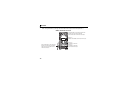
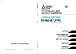
1.2.2
Parts
FR-A7AP connector (Refer to page 15.)
Use this connector to connect to the FR-A7AP/
FR-A7AL. Connecting to the FR-A7AP/FR-A7AL
enables the inverter to receive encoder feedback
data.
Shaft number switch
Set the shaft number.
(Refer to page 13.)
Mounting
hole
Front view
Rear view
789
Mounting
hole
4 56
CD
AB E
23
F01
FR-A7NS_B
FR-A7NS_T
2
1
FR-A7NS
O
N
SW1
Mounting hole
Connector
Connect to the inverter option connector.
2
1
Switch for manufacturer
setting
Do not change from initiallyO
set status (1:
).
N
SSCNET III cable connector (CN1A) (Refer to page 26.)
Connect the servo system controller, the preceding
axis inverter or the servo amplifier.
SSCNET III cable connector (CN1B) (Refer to page 26.)
Connect the following axis inverter or the servo amplifier.
For the final axis, puts a cap.
8
PRE-OPERATION INSTRUCTIONS
1.3
Caution
(1) Refer to the following manuals or software HELP for full information on the servo system controller.
y Q173DCPU/Q172DCPU user's manual ................................................... IB-0300133
y Q173DCPU/Q172DCPU motion controller (SV13/SV22)
programming manual (real mode version)................................................ IB-0300136
y Q173DCPU/Q172DCPU motion controller
programming manual (common mode version)........................................ IB-0300134
y Q173DCPU/Q172DCPU motion controller (SV13/SV22)
programming manual (Motion SFC version)............................................. IB-0300135
y Q173DCPU/Q172DCPU motion controller (SV22)
programming manual (virtual mode version) ............................................ IB-0300137
1
(2) Servo System Controller NETwork ΙΙΙ is abbreviated to SSCNET ΙΙΙ in this manual.
9
PRE-OPERATION INSTRUCTIONS
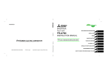
1.4
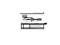
Operation Overview
In communication with the Mitsubishi servo system controller, the inverter operation (speed control or
position control or torque control under vector control with encoder) or monitoring can be performed from a
program on the servo system controller.
Application of optical communication method greatly improved the communication speed and noise
resistance of the SSCNET ΙΙΙ as compared with the conventional SSCNET. In addition, 50m of the
maximum wiring length between stations is realized.
Servo system controller
Motion control
FR-A700
FR-A7NS
Torque command
Position command
Speed command SSCNETΙΙΙ
Torque command *2 interface
Control command
Emergency stop *1
Monitor data
Parameter
*1
*2
10
Speed command
SSCNETΙΙΙ
Position
interface command
Position
Speed
control
control
Current
monitor
FR-A7AP/
FR-A7AL
Speed monitor/feedback pulse monitor
Encoder
interface
When the emergency stop signal is input, the inverter shuts off the output and the motor coasts.
Please contact your sales representative when performing torque control.
Emergency stop
output shutoff
Torque
control *2
IM
Encoder
PRE-OPERATION INSTRUCTIONS
CAUTION
y Mounting both the FR-A7NS and FR-A7AP/FR-A7AL and performing vector control enables SSCNET ΙΙΙ
communication.
When operating the inverter with the FR-A7NS mounted and without FR-A7AP/FR-A7AL, option alarm
(E.OPT) occurs. (Refer to page 77.) Also option alarm (E.OPT) occurs when the FR-A7AP and FR-A7NS are not
connected with the FR-A7AP connection cable (the FR-A7AL and FR-A7NS are not connected with the FRA7NS connection cable) during a stop of the inverter. (Refer to page 77.) (In those conditions, however, option
fault (E.OPT) does not occur when Pr.800 Control method selection = "9" (vector control test operation) (refer to
page 49) or when Pr.499 SSCNET III operation selection = "9999" (operation invalid). (refer to page 42))
y An alarm such as overcurrent shut off (E.OC3) and position error large (E.OD) may occur depending on the
status of the motor current and droop pulses during inverter operation.
11
1
2
INSTALLATION
2.1
Pre-Installation Instructions
Make sure that the input power of the inverter is off.
CAUTION
With input power on, do not install or remove the plug-in option. Otherwise, the inverter and
plug-in option may be damaged.
For prevention of damage due to static electricity, touch nearby metal before touching this
product to eliminate static electricity from your body.
12
INSTALLATION
2.2
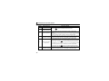
Shaft number Setting
ySetting with shaft number switch
Set the shaft number between "0H to FH" using shaft number switches on the FR-A7NS (refer to page 8).
The setting is reflected at the next power-on or inverter reset.
Set the arrow (×) of the corresponding switches to the number and alphabet to set a desired shaft
number.
CD
AB E
45
23 6
F01
789
Initial status
No.
Definition
No.
Definition
0
1
2
3
4
5
6
7
1st axis
2nd axis
3rd axis
4th axis
5th axis
6th axis
7th axis
8th axis
8
9
A
B
C
D
E
F
9th axis
10th axis
11th axis
12th axis
13th axis
14th axis
15th axis
16th axis
2
CAUTION
BCDE
F01
45
23
F01
45
23
BCDE
Good
Bad
example example
89
67 A
y Set the shaft number switch to the switch number (alphabet) position correctly. If
the switch is set between numbers, normal data communication can not be
made.
89
67 A
y You cannot set the same shaft number to other devices on the network. (Doing so disables proper
communication.)
y Set the inverter shaft number before switching on the inverter and do not change the setting while
power is on. Otherwise you may get an electric shock.
13
INSTALLATION
2.3
Installation Procedure
1)Remove the inverter front cover.
1)
2)Mount the hex-head screw for option
mounting into the inverter screw hole
(on earth plate). (size 5.5mm,
tightening torque 0.56N⋅m to 0.75N⋅m)
Screw hole for
option mounting
Inverter side
option
connector
3)
Screw hole for
option mounting
(on earth plate)
Hex-head screw
for option mounting
2)
4) Mounting
3)Securely fit the connector of the plug-in
option to the inverter connector along
the guides.
4)Securely fix the both right and left sides
of the plug-in option to the inverter with
the accessory mounting screws.
(Tightening torque 0.33N⋅m to
0.40N⋅m) If the screw holes do not lineup, the connector may not have been
plugged snugly. Check for loose
plugging.
screws
REMARKS
y Remove a plug-in option after removing two screws on both left and right sides.
(The plug-in option is easily removed if the control circuit terminal block is removed before.)
14
INSTALLATION
CAUTION
y When using this option unit, mount it in the "option connector 3 (lowermost
connector)" of the inverter.
If it is fitted in option connector 1 or 2, "
" or "
" (option alarm)
is displayed and the inverter will not function. In addition, when the inverter can
not recognize that the option is mounted due to improper installation, etc.,
Mounting
Position
Error
Display
Connector 1
Connector 2
"
" (option alarm) is displayed even if the option is fitted in the option
Connector 3
connector 3.
y Mount the FR-A7AP/FR-A7AL to the "option connector 2" of the inverter.
y After mounting both of the FR-A7NS and FR-A7AP/FR-A7AL, connect each external connector using the FRA7AP connection cable (Refer to page 7) / FR-A7NS connection cable (enclosed in FR-A7AL, refer to the instruction
manual of FR-A7AL.) respectively.
When using FR-A7AP
FR-A7AP
External
connector
FR-A7NS
When using FR-A7AL
FR-A7AL
External
connector
FR-A7NS
FR-A7AP
connection
cable
FR-A7NS
connection
cable
y Take care not to drop a hex-head screw for option mounting or mounting screw during mounting and removal.
y Pull out the option straight to remove. Otherwise, the connector may be damaged.
15
2
3
WIRING
3.1
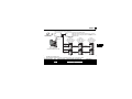
System configuration (when FR-A7AP is used)
zConnecting with the motion controller
Motion controller
(Q173DCPU/Q172DCPU)
Inverter
FR-A700 series
+ FR-A7NS + FR-A7AP
(or servo amplifier
MR-J3- B)
SSCNET ΙΙΙ cable *2
Inverter
FR-A700 series
+ FR-A7NS + FR-A7AP
(or servo amplifier
MR-J3- B)
SSCNET ΙΙΙ cable *2
1st axis
*1
*2
SSCNET ΙΙΙ cable *2
2nd axis
16th axis *1
The maximum number of inverter (or servo amplifier) connected differs depending on the type of motion controller
(Q173DCPU/Q172DCPU).
For the distance between electrodes of SSCNET ΙΙΙ cable, refer to the following table.
Cable Model Name Type Cable Length (m) Distance Between Electrodes (m)
MR-J3BUS
M
MR-J3BUS
M-A
MR-J3BUS
M-B
16
Inverter
FR-A700 series
+ FR-A7NS + FR-A7AP
(or servo amplifier
MR-J3- B)
POF
HPCF
0.15 to 3
5 to 20
30 to 50
20
50
Applications
Standard code inside panel
Standard cable outside panel
Long-distance cable
WIRING
zConnecting with the motion board
Motion board(Q111BD-SSC/Q110BD-SSC)
Number of mountable boards:
4 boards maximum (128 axis total (32 axis 4 boards))
Specify board ID using the board ID setting switch of the
motion board.
Inverter OS software
(For the A7NS)
PCI bus
Personal computer
(PC/AT compatible)
(Windows 2000 /Windows XP )
R
Inverter
Inverter
FR-A700 series
FR-A700 series
+ FR-A7NS + FR-A7AP + FR-A7NS + FR-A7AP
(or servo amplifier
(or servo amplifier
MR-J3- B)
MR-J3- B)
SSCNET ΙΙΙ
(Line 1)
SSCNET ΙΙΙ
cable *2
SSCNET ΙΙΙ
cable *2
SSCNET ΙΙΙ
cable *2
SSCNET ΙΙΙ
cable *2
SSCNET ΙΙΙ
(Line 2)
1st axis
*2
3
SSCNET ΙΙΙ
cable *2
R
SSCNET ΙΙΙ
cable *2
*1
Inverter
FR-A700 series
+ FR-A7NS + FR-A7AP
(or servo amplifier
MR-J3- B)
2nd axis
16th axis *1
The maximum number of inverter (or servo amplifier) connected differs depending on the type of motion board
(Q111BD-SSC/Q110BD-SSC).
For the distance between electrodes of SSCNET ΙΙΙ cable, refer to the following table.
Cable Model Name Type
MR-J3BUS
M
MR-J3BUS
M-A
MR-J3BUS
M-B
POF
HPCF
Cable Length (m) Distance Between Electrodes (m)
0.15 to 3
5 to 20
30 to 50
20
50
Application
Standard code inside panel
Standard cable outside panel
Long-distance cable
17
WIRING
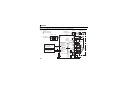
3.2
Wiring example (when FR-A7AP is used)
zVector control dedicated motor (SF-V5RU, SF-THY), 12V complementary
MCCB
Sink logic
Main circuit terminal
Control circuit terminal
MCCB
Three-phase
AC power supply *1
MC
Servo system controller,
preceding axis inverter
(servo amplifier)
Following axis inverter
(servo amplifier)
18
SSCNET ΙΙΙ
cable
FAN
U
V
IM
W
E
Earth
External
(Ground) Thermal relay
PC
thermal
protector
G1
2W1kΩ
relay input *2 CS(OH)
G2
SD
FR-A7AP
SSCNET ΙΙΙ unit
A *3
PA1
FR-A7NS
FR-A7AP
B
PA2
connection
SSCNET III
cable connector cable
C
PB1
(CN1A)
FR-A7AP
D
PB2
connector
Encoder
F
Differential PZ1
SSCNET III
*4
G
PZ2
cable connector
(CN1B)
S
Complementary PG
Earth terminal
SD
R
Terminating
resistor PG
ON
SD
*5
*6 *8
(+) (-) 12VDC power supply *7
OFF
Inverter
R/L1
S/L2
T/L3
Three-phase
AC power supply
SF-V5RU, SF-THY
A
B
C
U
V
W
WIRING
*1
*2
For the fan of the 7.5kW or less dedicated motor, the power supply is single phase. (200V/50Hz, 200 to 230V/
60Hz)
Assign OH (external thermal input) signal to the terminal CS. (Set "7" in Pr. 186 )
CS(OH)
Connect a 2W1kΩ resistor between the terminal PC and CS (OH). Install the
PC
resistor pushing against the bottom part of the terminal block so as to avoid a
Control circuit
contact with other cables.
terminal block
Refer to FR-A700 Instruction Manual (Applied) for details of Pr.186 CS terminal
function selection.
Resistor (2W1kΩ)
*3
*4
*5
*6
*7
*8
The pin number differs according to the encoder used.
Speed control and torque control are properly performed even without connecting Z phase.
Connect the encoder so that there is no looseness between the motor and motor shaft. Speed ratio should be 1:1.
Earth (Ground) the shielded cable of the encoder cable to the enclosure with a P clip, etc.
(Refer to FR-A7AP Instruction Manual.)
For the complementary, set the terminating resistor selection switch to off position.
(Refer to FR-A7AP Instruction Manual.)
A separate power supply of 5V/12V/15V/24V is necessary according to the encoder power specification.
For terminal compatibility of the FR-JCBL, FR-V7CBL and FR-A7AP, refer to FR-A7AP Instruction Manual.
19
3
WIRING
3.3
SSCNET III cable
Use our optional SSCNET ΙΙΙ connection cables.
(1) Cable type
Cable Model Name *1
MR-J3BUS
M
MR-J3BUS
M-A
MR-J3BUS
M-B *2
*1
*2
20
Type
POF
HPCF
Cable Length (m)
Flex Life
Application
0.15, 0.3, 0.5, 1, 3
5, 10, 20
30, 40, 50
Standard
Standard
Long flex
Standard code inside panel
Standard cable outside panel
Long-distance cable
in the type represents the cable length.
Symbol
015
03
05
1
3
5
10
20
30
40
50
Cable Length (m)
0.15
0.3
0.5
1
3
5
10
20
30
40
50
For cable of 30m or less, contact our company.
WIRING
(2) Specifications
MR-J3BUS
M
0.3 to 3
70N
MR-J3BUS
M-A
MR-J3BUS
M-B
5 to 20
30 to 50
Enforced covering cord: 50 Enforced covering cord: 50
Cord: 25
Cord: 30
25
980N
420N
(Enforced covering cord) (Enforced covering cord)
140N
-40 to 85°C
-20 to 70°C
2.2 0.07
4.4 0.1
4.4 0.1
7.6 0.1
*2
4.4 0.4
2.2 0.2
External
appearance
(mm)
*1
3
Indoors (no direct sunlight)
No solvent or oil
Ambient
2.2 0.07
Optical
Cable
(Cord)
0.15
2.2 0.07
Cable Length (m)
Minimum
Bend Radius
(mm) *1
Tension
Strength
Temperature
Range For
Use *2
7.6 0.5
Make sure to lay the cable with greater radius than the minimum bend radius. Do not press the cable to edges of
equipment or others.
This temperature range for use is the value for optical cable (cord) only. Temperature condition for the connector is
the same as that for inverter.
21
WIRING
(3) Outline drawings
zMR-J3BUS015M
(15) (13.4)
(37.65)
(20.9)
Protective tube (6.7)
(1.7)
(2.3)
8+0
+50
150 −0
(Unit: mm)
zMR-J3BUS03M to MR-J3BUS3M
Protective tube
*
*
(100)
(100)
L
(Unit: mm)
*
22
Dimension of connector part is the same as that of MR-J3BUS015M.
Cable Model Name
MR-J3BUS03M
MR-J3BUS05M
MR-J3BUS1M
MR-J3BUS3M
Cable Length (L) (m)
0.3
0.5
1
3
WIRING
zMR-J3BUS5M-A to MR-J3BUS20M-A, MR-J3BUS30M-B to MR-J3BUS50M-B
Protective tube
*
*
A
B
B
A
L
*
Dimension of connector part is the same as that of MR-J3BUS015M.
Cable Model
MR-J3BUS5M-A MR-J3BUS10M-A MR-J3BUS20M-A MR-J3BUS30M-B MR-J3BUS40M-B MR-J3BUS40M-B
Name
Cable Length
100
150
(A) (mm)
Cable Length
30
50
(B) (mm)
Cable Length
5
10
20
30
40
50
(L) (m)
CAUTION
y Do not see directly the light generated from the end of SSCNET ΙΙΙ cable. When the light gets into eye, you
may feel something is wrong for eye. (The light source of SSCNET ΙΙΙ corresponds to class1 defined in
IEC60825-1.)
23
3
WIRING
3.3.1
SSCNET III cable laying
SSCNET ΙΙΙ cable is made of optical fiber. Application of a power, such as a major shock, lateral pressure,
haul, and abrupt bending or twisting, to the optical fiber will deform or break the inside, disabling optical
transmission. Especially, the optical fibers of the MR-J3BUS
M, MR-J3BUS
M-A which is made of
synthetic resin will melt down if exposed to fire and high temperature. Therefore, avoid the cable from
contacting with the hot section such as heatsink of the inverter and an option for regeneration.
Read described item of this subsection carefully and handle it with caution.
(1) Minimum bend radius
Make sure to lay the cable with greater radius than the minimum bend radius. Do not press the cable to
edges of equipment or others. For SSCNET ΙΙΙ cable, the appropriate length should be selected with due
consideration for the dimensions and arrangement of inverter. Ensure that the cable bend will not become
smaller than the minimum bend radius if the SSCNET ΙΙΙ cable is pressed down when the door of the
enclosure is closed.
For the minimum bend radius, refer to page 21.
(2) Bundle fixing
Use the accessory cable tie to bundle the SSCNET ΙΙΙ cable outside the inverter, and fix the bundled cable
to the installation surface of the inverter. Fix the SSCNET ΙΙΙ cable using a cable tie by gently slackening
the optical code with keeping a larger radius than the minimum bend radius, and it should not be twisted.
(Refer to page 31.) When binding the cable with a cable tie other than the provided one, use a cushioning
material such as plasticizer-free sponge and rubber to fix it.
Never use vinyl tape for cord. Plasticizing material in vinyl tape goes into optical fiber and lowers the optical
characteristic. At worst, it may cause wire breakage. If using adhesive tape for cable laying, the fire
resistant acetate cloth adhesive tape 570F (Teraoka Seisakusho Co., Ltd) is recommended.
If laying with other wires, do not make the cable touched wires or cables made from soft polyvinyl chloride
(PVC), polyethylene resin (PE), Fluorocarbon resin or nylon which contains plasticizing material.
24
WIRING
(3) Tension
Applied tension to fiber optics causes external force to concentrate in the section where fiber optics are
fixed and an optical connector is connected, increasing transmission loss. If a larger pressure is further
applied, this could cause a disconnection of optical fibers and a damage to the optical connector. For cable
laying, handle without putting forced tension. For the tension strength, refer to page 21.
(4) Lateral pressure
Applying a lateral pressure to the fiber cable deforms the cable itself and applies pressure to the internal
fiber, resulting in increase in transmission loss. Moreover, if a larger pressure is further applied, the optical
cable may be disconnected in the worst case. As the same condition also occurs at cable laying, do not
tighten up optical cable with a thing such as nylon band (TY-RAP).
Do not trample it down or tuck it down with the door of enclosure or others.
(5) Twisting
If optical fiber is twisted, it will become the same stress added condition as when local lateral pressure or
bend is added. This could increase a transmission loss. Moreover, if a larger pressure is further applied,
the optical cable may be disconnected in the worst case.
25
3
WIRING
3.4
Wiring
(1) Open the inverter front cover, remove the cap of FR-A7NS's connector (CN1A, CN1B) for SSCNET ΙΙΙ
cable connection, and insert a SSCNET ΙΙΙ cable.
Refer to page 20 for types of SSCNET ΙΙΙ cable.
1) Cap for the connector
1)
2)
3)
1)
26
2) SSCNET III cable connector (CN1A)
Connect the servo system controller, the preceding
axis inverter or the servo amplifier.
3) SSCNET III cable connector (CN1B)
Connect the following axis inverter or the servo
amplifier. For the final axis, puts a cap.
WIRING
(2) Route the wires for the FR-A700 series (22K or less) as shown below. For the cables connected to the
SSCNET ΙΙΙ cable connector (CN1A), route them between the control circuit terminal block and front
cover.
LED1
1
2
O
N
SW2
SW3
Route the SSCNET ΙΙΙ cable with paying
attention for avoiding the case that the cable
bend becomes smaller than the minimum
bend radius.
LED2
LED3
1
2
3
4
O
N
BCDE
F01
45
23
89
67 A
FR-A7NS_B
FR-A7NS_T
2
1
O
N
SW1
Option slot 2
For installation of FR-A7AP
FR-A7AP
vv
Cut off with
a nipper, etc.
3
FR-A7NS
CN1A
Option slot 3
For installation of FR-A7NS
Control circuit terminal block
CN1B
Cut off a hook on the inverter front
cover side surface.
(Cut off so that no portion is left.)
Route the SSCNET ΙΙΙ cable with paying attention for avoiding the case
that the cable bend becomes smaller than the minimum bend radius.
27
WIRING
REMARKS
y When the hook of the inverter front cover is cut off for wiring, the protective structure (JEM1030) changes to open
type (IP00).
y The SSCNET ΙΙΙ cable connected to CN1B of FR-A700 series (22K or less) must be pulled out to the left side of the
inverter. Therefore, leave enough space on the left side of the inverter in consideration of the minimum cable bend
radius.
y In a vibration-free environment, the cables connected to the SSCNET ΙΙΙ cable connector (CN1A) can be pulled out
from the side surface of the inverter. Use the space that will be made by cutting off the hook of the front cover.
O
N
SW2
LED1
1
2
1
2
3
4
Protective tape *
SW3
Route the SSCNET ΙΙΙ cable with paying
attention for avoiding the case that the
cable bend becomes smaller than the
minimum bend radius.
LED2
LED3
O
N
FR-A7AP
F01
89
67 A
FR-A7NS_B
FR-A7NS_T
2
1
O
N
Route the SSCNET ΙΙΙ cable with paying
attention for avoiding the case that the
cable bend becomes smaller than the
minimum bend radius.
*
28
SW1
Option slot 2
For installation of FR-A7AP
45
23
BCDE
SW1
FR-A7NS
Option slot 3
For installation of FR-A7NS
Control circuit terminal block
Since the SSCNET ΙΙΙ cable touches the edge of the inverter case, wind the protective tape around the
cable to protect it.
WIRING
(3) For wiring of FR-A700 series (30K or more), use the space on the left side of the control circuit terminal
block.
LED1
1
2
O
N
SW2
SW3
Route the SSCNET ΙΙΙ cable with paying
attention for avoiding the case that the
cable bend becomes smaller than the
minimum bend radius.
LED2
LED3
1
2
3
4
O
N
FR-A7AP
F01
89
67 A
FR-A7NS_B
FR-A7NS_T
2
1
O
N
3
Option slot 2
For installation of FR-A7AP
45
23
BCDE
SW1
FR-A7NS
Option slot 3
For installation of FR-A7NS
SW1
CN1A
Control circuit terminal block
CN1B
REMARKS
y The inverter type of 22K and 30K of FR-A700 series in each -NA, -EC versions are as follows.
FR-A720-22K
FR-A740-22K
FR-A720-30K
FR-A740-30K
NA
EC
FR-A720-00900-NA
FR-A740-00440-NA
FR-A720-01150-NA
FR-A740-00570-NA
⎯
FR-A740-00620-EC
⎯
FR-A740-00770-EC
29
WIRING
(4) When installing 3 plug-in options or using FR-A7AL, option slot 1 is mounted by plug-in options. In such
case, wiring as shown in (2) and (3) cannot be made. Use the space above the option slot 1.
<When FR-A7AP is used>
Route the SSCNET ΙΙΙ cable with paying attention
for avoiding the case that the cable bend
becomes smaller than the minimum bend radius.
LED1
1
2
O
N
SW2
SW3
Option slot 1
Available for the installation of FR-A7AY, FR-A7AR, etc.
LED2
LED3
1
2
3
4
O
N
FR-A7AP
2
1
30
FR-A7NS_T
O
N
SW1
Option slot 2
For installation of FR-A7AP
89
67 A
FR-A7NS_B
Route the SSCNET ΙΙΙ cable with paying
attention for avoiding the case that the
cable bend becomes smaller than the
minimum bend radius.
F01
45
23
BCDE
SW1
FR-A7NS
Option slot 3
For installation of FR-A7NS
Control circuit terminal block
WIRING
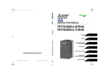
(5) Fixing the SSCNET ΙΙΙ cable with a cable tie
Fix the SSCNET ΙΙΙ cable to the installation surface of the
inverter using the accessory cable tie to prevent the
SSCNET ΙΙΙ cable from getting a damage caused by
vibration, etc. Gently slacken the cable with keeping a
larger radius than the minimum bend radius, and it should
not be twisted.
Inverter installation
surface
Inverter
3
Loose slack
Fix the SSCNET ΙΙΙ cable
using the accessory cable
clamp and cable tie.
CAUTION
When performing wiring using the space between the inverter front cover and control circuit
terminal block, run the cable keeping the minimum bend radius or more so as not to subject the
cable to stress. In addition, take care that cables do not contact with the hot section. (Refer to page 24.)
After wiring, wire offcuts must not be left in the inverter. They may cause an error, failure or
malfunction.
31
4
SSCNET III COMMUNICATION STATUS
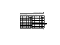
When power is turned on with the SSCNET ΙΙΙ communication unit (FR-A7NS) mounted to the option
connector 3 and FR-A7AP/FR-A7AL mounted to the option connector 2, the inverter goes in standby of
initialization of the SSCNET ΙΙΙ communication. Then, the status shifts to SSCNET ΙΙΙ operation mode,
changing to the external operation mode and PU operation mode is not enabled. In addition, Pr.79
Operation mode selection setting is made invalid. The following shows the communication description of
SSCNET ΙΙΙ communication.
The status of communication with the servo system controller can be monitored as a SSCNET ΙΙΙ
communication status.
For monitoring, set "39" (SSCNET ΙΙΙ communication status monitor) in Pr.52 DU/PU main display data selection
and select output voltage monitor with the PU (FR-DU07/FR-PU07/FR-PU04). (Refer to page 48.)
The figure in the page 33 shows the status transition during communication from the motion controller/board to the
inverter.
The list of SSCNET ΙΙΙ communication status is shown on page 34.
32
SSCNET III COMMUNICATION STATUS
Mount the FR-A7NS to the option connector 3 of the inverter
Mount the FR-A7AP/FR-A7AL to the option connector 2 of the inverter *1
Power on the inverter
120
Waiting for power on (SSCNET ΙΙΙ communication)
of the servo system controller *2
Power on the servo system controller (SSCNET ΙΙΙ communication starts)
121
130
140
150
160
180
2##
Initial data communication with the servo
system controller (initialized communication)
Ready off/servo off
Ready on
Alarm code is
displayed at
occurrence of alarm
3##
Ready on/servo off
Servo on
4##
Ready on/servo on
Normal operation
When an alarm/warning
number is displayed
At occurrence of overcurrent shutoff
(E.OC3)
900
At occurrence of stall prevention (OL)
800
At an emergency stop of the
servo system controller
800
Alarm reset or warning cancel *3
*1 If the FR-A7AP/FR-A7AL is not
mounted to the option connector 2, the
inverter displays an option alarm
(E.OPT). (Note that an option alarm
(E.OPT) will not occur when Pr.800
Control method selection = “9" or Pr.499
SSCNET III operation selection =
"9999".)
*2 Inverter operation mode changes to
"SSCNET ΙΙΙ operation mode" and can
not be changed to external operation
and PU operation. In addition,
operation mode setting of the Pr.79
Operation mode selection is made
invalid.
*3 Refer to page 43 for the reset method of
the inverter protective function. In
addition, if the inverter protective
function is reset by powering off and on
the inverter power, the inverter
recovers in the communication waiting
condition after powering on again.
Power off the servo system controller
110
Power on the servo system controller
indicates the
SSCNET ΙΙΙ communication.
(Refer to page 34.)
33
4
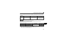
SSCNET III COMMUNICATION STATUS
SSCNET III
Communication Operation
Status
110
120
121
130
140
150
160
180
2##
3##
4##
800
900
*
Description
y When the power of the servo system controller turned off after SSCNET ΙΙΙ
communication establishment.
y When Pr. 499 SSCNET III operation selection = "9999" (Operation invalid mode).
When the SSCNET ΙΙΙ communication status displays "120", possible causes are as follows.
y When the inverter power is on when the servo system controller power is off.
y When an inverter failure or a communication error with the servo system controller
occurs. The display of the SSCNET ΙΙΙ communication status at this time is as follows:
"120"→"130"→"140"→"120"
y When the servo system controller is in faulty.
y When initialization has never completed after powering on the power.
During
initialization y During initial setting of the communication specifications
y When the shaft numbers set by the servo system controller and the inverter shaft
*
number switch are not the same.
The display of the SSCNET ΙΙΙ communication status at this time is as follows:
"120"→"121"→"120"→"120"
When communication initialization setting has completed and the inverter is in
synchronization with the servo system controller.
During preliminary communication with the servo system controller.
During motor and encoder data communication with the servo system controller.
During initial signal data communication with the servo system controller.
During completion operation of initial data communication with the servo system controller.
Ready off Ready off/servo off was received. ## indicates the shaft number.
Servo off Ready on/servo off was received. For example, the first shaft is indicated as 201, 301 or
Servo on Ready on/servo on was received. 401.
Warning Warning ("Minor fault"/"alarm" of the inverter alarm)
Alarm
Inverter alarm ("Major fault" of the inverter alarm)
During initialization, "CF" (CF warning) may be displayed on the operation panel. Moreover, "CF" and the communication
status number are displayed alternately on the SSCNET ΙΙΙ communication status monitor. (Refer to page 48 for the
SSCNET ΙΙΙ communication status monitor.)
34
5
INVERTER SETTING AND DISPLAY
5.1
Parameter List
The following parameters are used for the plug-in option (FR-A7NS).
Set the values according to need.
Parameter
Number
Name
52
DU/PU main display data selection
185
JOG terminal function selection
379 *1, 2
449 *1
499 *1, 3
800 *4
*1
*2
*3
*4
SSCNET ΙΙΙ rotation direction
selection
SSCNET ΙΙΙ input filter setting
SSCNET ΙΙΙ operation selection
Control method selection
Setting Range
0, 5 to 14, 17, 18, 20, 23 to 25,
32 to 34, 39, 50 to 57, 100
0 to 20, 22 to 28, 42 to 44, 62,
64 to 71, 76, 9999
Minimum
Initial
Setting
Value
Increments
Refer
to
Page
1
0
48
1
5
49
0, 1
1
0
47
0 to 4
0, 1, 9999
0 to 5, 9, 10, 11, 12, 20
1
1
1
4
0
20
48
42
49
Parameters which can be displayed when the plug-in option (FR-A7NS) is mounted.
The setting is reflected after the CPU reset of the servo system controller or at the next power-on.
When a value set in Pr. 499 is changed from "a value other than 9999" to "9999" or from "9999" to "a value other
than 9999", the setting is reflected after the inverter reset or at the next power-on.
When a value set in Pr. 800 is changed from "a value other than 9" to "9" or from "9" to "a value other than 9", the
setting is reflected after the inverter reset or at the next power-on.
35
5
INVERTER SETTING AND DISPLAY
5.2
Operation Mode Setting
The inverter mounted with a communication option has three operation modes.
(1) PU operation [PU].............. Controls the inverter from the key of the operation panel (FR-DU07)
mounted on the inverter.
(2) External operation [EXT] ... Controls the inverter by switching on/off external signals connected to the
control circuit terminals of the inverter.
(The inverter is factory-set to this mode.)
(3) Network operation [NET] ... Controls the inverter with instructions from the network via the
communication option.
Pr. 79, Pr. 338, Pr. 339, Pr. 340 and Pr. 550 are invalid during SSCNET ΙΙΙ
operation.
Operation mode is displayed as "NET" during SSCNET ΙΙΙ operation.
5.2.1
Operation mode indication
FR-DU07
Operation mode indication
(The inverter operates according to the LED lit mode.)
PU: PU operation mode
EXT: External operation mode
NET: SSCNET III operation mode
36
INVERTER SETTING AND DISPLAY
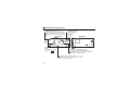
5.2.2
Operation mode switchover method
Power-on
2) (When Pr. 79 = "0" (factory setting))
1)
SSCNETIII operation
C
External operation
A
PU operation
B
D
E
F
(1) Starting operation mode
Symbol
1)
2)
Switchover Type
SSCNET ΙΙΙ operation mode
External operation
(Pr. 79 = 0 (factory setting))
5
Switchover Method
Turning on the servo system controller and inverter power with the
FR-A7NS and FR-A7AP/FR-A7AL mounted starts the inverter in
SSCNET ΙΙΙ operation mode, starting initialize communication from
the servo system controller. SSCNET ΙΙΙ operation is enabled at
completion of initialize communication. (When initialized
communication has not completed, the inverter displays
.)
Powering on the inverter without the FR-A7NS mounted starts the
inverter in external operation mode.
37
INVERTER SETTING AND DISPLAY
(2) Operation mode switchover (When Pr. 79 = “0”)
Symbol
A
B
C
D
E
Switchover Type
External operation →
PU operation
PU operation →
External operation
Switchover Method
Press the
of the PU (FR-DU07/FR-PU07/FR-PU04)
y The operation mode can not be switched in power-on status. After
powering off the inverter, remove the FR-A7NS, then power on the inverter
SSCNET ΙΙΙ operation →
again.
External operation
y Set "9999" in Pr.499 SSCNET III operation selection. Then, restart the inverter
again by making a power-on reset or reset using the RES signal.
The operation mode can not be switched in power-on status. After powering
External operation →
off the inverter, mount the FR-A7NS to the option connector 3 and FR-A7AP/
SSCNET ΙΙΙ operation
FR-A7AL to the option connector 2, then power on the inverter again.
y The operation mode can not be switched in power-on status. After
powering off the inverter, remove the FR-A7NS, then power on the inverter
again. Then, press the
of the PU (FR-DU07/FR-PU07/FR-PU04).
SSCNET ΙΙΙ operation →
PU operation
y Set "9999" in Pr.499 SSCNET III operation selection, then restart the inverter
by making a power-on reset or resetting the inverter using the RES
signal.Then, press the
F
38
PU operation →
SSCNET ΙΙΙ operation
of the PU (FR-DU07/FR-PU07/FR-PU04).
The operation mode can not be switched in power-on status. After powering
off the inverter, mount the FR-A7NS to the option connector 3 and FR-A7AP/
FR-A7AL to the option connector 2, then power on the inverter again.
INVERTER SETTING AND DISPLAY
CAUTION
y In the SSCNET ΙΙΙ operation mode, the Pr. 79 Operation mode selection setting is invalid.
y Changes in the shaft number are reflected only at the next power-on. Therefore, if the shaft number is
changed, make sure to power off and on the inverter power.
y Even if SSCNET ΙΙΙ operation is being performed,
of the PU (FR-DU07/FR-PU07) can be used to make
a stop (when Pr. 75 Reset selection/disconnected PU detection/PU stop selection = “14 (factory setting) to 17”).
At this time, the deceleration time is 0s. Refer to the inverter manual for Pr. 75.
In addition, "
" is displayed in the PU. However, an alarm output is not provided. (Refer to page 76.)
REMARKS
y During SSCNET ΙΙΙ operation, "NET" is displayed to indicate the operation mode.
5
39
INVERTER SETTING AND DISPLAY
5.3
Operation at Communication Error Occurrence
5.3.1
Alarm and measures
(1) The inverter operates as follows at alarm occurrences.
Alarm
Location
Status
Inverter operation
Data communication
Communication Inverter operation
line
Data communication
Communication Inverter
operation
option
connection
Data
communication
Communication error
option
Inverter
Error of
operation
communication
Data
option itself
communication
Inverter
SSCNET ΙΙΙ
Operation
Operation Mode
External
Operation
Inverter trip
Continued
Inverter trip
Stop
Inverter trip
Continued
Continued
Stop
Inverter trip
Continued
Continued
Stop
Inverter trip
Inverter trip
Inverter trip
Continued
Continued
Continued
Inverter trip
Continued
Continued
Stop
Stop
Stop
PU Operation
(2) Measures at alarm occurrences
Alarm Indication
E.OP3
E.1, E.2
E.3
Alarm Definition
Measures
Communication line error Inspect the master. (Refer to page 78.)
Fit the communication option in the option connector 3. (Refer to page 15.)
Option alarm
Check the connection between the inverter and option unit for poor
contact, etc. and remove the cause of the error. (Refer to page 15.)
When alarms other than the above are displayed, refer to the inverter manual and remove the cause of the alarm.
40
INVERTER SETTING AND DISPLAY
5.4
Inverter Reset
The following inverter reset is enabled during SSCNET ΙΙΙ communication (SSCNET ΙΙΙ operation mode).
y Reset from the servo system controller at inverter alarm (Reset can be made only when the protective
function of the inverter is activated.)
y CPU reset of the servo system controller
y Turn on the terminal RES (RES signal)
y Switch off inverter power
y Inverter reset from the PU
y Reset from the PU/DU at inverter alarm
REMARKS
y Refer to Pr. 499 SSCNET III operation selection (page 42) for the operation of inverter reset from the servo system
controller.
CAUTION
y When the inverter reset occurs with the FR-A7NS mounted, the inverter restarts in the SSCNET ΙΙΙ operation
mode in the initial status.
y The inverter can not be controlled for about 1s after release of a reset command .
41
5
INVERTER SETTING AND DISPLAY
5.5
Setting SSCNET III communication function
5.5.1
Pr.499 SSCNET III operation selection
Operation at occurrence of communication disconnection can be selected and operation mode during
SSCNET ΙΙΙ communication can be disabled.
Alarm reset
SSCNET ΙΙΙ
by CPU reset
Pr.499 Operation Operation at
of the servo
Setting
mode
communication
system
disconnection
controller
0
(initial
value)
Normal
operation
mode
1
9999
Operation
invalid
mode *3
Output shutoff
(coasting) *1
Valid
Output shutoff
(coasting) →
communication
option alarm
(E.OP3) *2
Invalid
⎯
⎯
Description
*1 The inverter output is shutoff at occurrence of
communication disconnection.
(If a communication disconnection occurs after the inverter
alarm is activated, reset the inverter.)
*2 The inverter output is shutoff at occurrence of
communication disconnection, and the communication
option alarm (E.OP3) is displayed. (Refer to page 78)
(Inverter reset is necessary to restart inverter operation.)
*3 SSCNET ΙΙΙ communication is invalid.
(The inverter operates as same as when the FR-A7NS is
not mounted.)
Since mounting the FR-A7NS restricts the inverter
operation mode, parameters, etc., set "9999" to cancel
the restrictions applied by the FR-A7NS. (Communication
is made valid after inverter reset.)
REMARKS
y If communication data is in a CRC error etc., communication option alarm (E.OP3) occurs regardless of the Pr. 499 setting.
y Refer to page 43 for the reset method of the inverter alarm.
y "E.OP3" is displayed at occurrence of communication disconnection if "1" is set in Pr. 499 SSCNET III operation
selection. If "E.OP3" cannot be reset with the inverter reset, reset the CPU of the servo controller system.
42
INVERTER SETTING AND DISPLAY
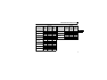
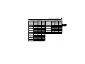
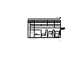
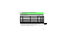
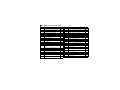
z Reset method of the inverter alarm
The reset methods of the inverter alarm are as follows: ({: Valid, ×: Invalid)
y When Pr. 499 = "0 (initial value)"
Display
Name
E.OC3 *1 Overcurrent shut-off
Regenerative
E.OV3 *1
overvoltage shut-off
Inverter overload shutE.THT *1 off (electronic thermal
relay function)
Motor overload shutE.THM *1 off (electronic thermal
relay function)
E.FIN Fin overheat
Instantaneous power
E.IPF
failure
E.UVT Undervoltage
E.ILF
Input phase failure
E.OLT *1 Stall prevention
Brake transistor alarm
E.BE
detection
Servo
System
Inverter
Reset Controller
Error CPU
*2
Reset Reset
{
{
{
{
{
{
{
{
{
{
{
{
{
{
{
{
{
{
{
{
{
Display
E.GF
E.LF
{
×
×
{
{
{
{
×
×
E.OHT *1
E.PTC *1
Name
Servo
System
Inverter
Reset Controller
Error CPU
*2
Reset Reset
Output side earth
(ground) fault
overcurrent
{
×
×
Output phase failure
{
×
×
{
{
{
{
{
{
{
×
×
{
{
{
{
×
×
{
{
{
{
×
×
{
×
×
External thermal relay
operation
PTC thermistor
operation
E.OPT Option alarm
Communication option
alarm
Parameter storage
E.PE
device alarm
E.PUE PU disconnection
Parameter storage
E.PE2
device alarm
E.OP3
E.CPU CPU error
43
5
INVERTER SETTING AND DISPLAY
Display
Name
Operation panel power
supply short circuit, RSE.CTE
485 terminal power
supply short circuit
24VDC power output
E.P24
short circuit
Output current
E.CDO detection value
exceeded
Inrush current limit
E.IOH
circuit alarm
Communication error
E.SER
(inverter)
E.AIE
Analog input error
USB communication
error
E.OS Overspeed occurrence
Speed deviation
E.OSD
excess detection
E.USB
E.ECT Open cable detection
E.OD
44
Excessive position
error
Servo
System
Inverter
Reset Controller
Error CPU
*2
Reset Reset
Display
E.EP
{
×
×
×
×
{
{
{
×
×
{
{
{
{
×
×
{
{
{
{
{
{
{
{
{
{
×
×
{
{
{
E.7
{
{
Option alarm
E.3
E.6
{
Encoder phase error
E.1
E.2
{
Name
Servo
System
Inverter
Reset Controller
Error CPU
*2
Reset Reset
{
{
CPU error
{
{
×
×
×
×
×
×
×
×
×
×
×
×
INVERTER SETTING AND DISPLAY
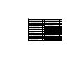
y When Pr. 499 = "1"
Display
Name
E.OC3 *1 Overcurrent shut-off
E.OV3 *1
E.THT *1
Regenerative
overvoltage shut-off
Inverter overload shutoff (electronic thermal
relay function)
Motor overload shut-off
(electronic thermal
relay function)
Servo
System
Inverter
Reset Controller
*2
Error CPU
Reset Reset
Display
Name
{
{
×
{
{
×
{
{
×
{
{
×
{
{
×
{
{
×
{
{
×
{
{
×
E.CPU CPU error
{
{
×
Operation panel
power supply short
E.CTE circuit, RS-485
terminal power supply
short circuit
{
{
×
{
{
×
E.LF
{
{
×
E.OHT *1
{
{
×
E.PTC *1
Output phase failure
External thermal relay
operation
PTC thermistor
operation
E.OPT Option alarm
E.FIN
Fin overheat
{
{
×
Communication option
E.OP3
alarm
Parameter storage
E.PE
device alarm
E.IPF
Instantaneous power
failure
{
{
×
E.PUE PU disconnection
{
{
E.PE2
E.THM *1
E.UVT Undervoltage
E.ILF
Input phase failure
E.OLT *1 Stall prevention
E.BE
E.GF
Brake transistor alarm
detection
Output side earth
(ground) fault
overcurrent
{
{
×
{
{
{
{
×
×
×
{
{
×
{
{
×
Servo
System
Inverter
Reset Controller
*2
Error CPU
Reset Reset
Parameter storage
device alarm
45
5
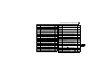
INVERTER SETTING AND DISPLAY
Display
Name
24VDC power output
short circuit
Output current
E.CDO detection value
exceeded
Inrush current limit
E.IOH
circuit alarm
Communication error
E.SER
(inverter)
E.P24
E.AIE
Analog input error
USB communication
E.USB
error
Servo
System
Inverter
Reset Controller
*2
Error CPU
Reset Reset
{
{
E.2
{
{
E.6
CPU error
{
{
{
{
{
{
{
{
{
{
×
×
×
×
×
{
{
×
{
{
×
{
{
×
{
{
×
Before resetting the inverter alarm, remove the
cause of the error and wait until the motor cools
down.
The inverter can be reset by powering off and on the
power, turning on the terminal RES (RES signal), or
pressing the
{
×
{
{
×
E.ECT Open cable detection
{
{
×
E.OD
Excessive position
error
{
{
×
E.EP
Encoder phase error
{
{
×
46
Option alarm
E.3
×
{
Overspeed occurrence
Name
E.1
×
Speed deviation
E.OSD
excess detection
E.OS
Display
Servo
System
Inverter
Reset Controller
*2
Error CPU
Reset Reset
E.7
*1
*2
key on the PU.
INVERTER SETTING AND DISPLAY
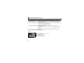
5.5.2
Pr.379 SSCNET III rotation direction selection
The rotation direction of the motor can be changed.
Before setting Pr.379 SSCNET III rotation direction selection, always match the Pr.359 Encoder rotation direction
setting (0/1) and rotation direction (CW/CCW) of the encoder as viewed from the load side of the motor.
Motor rotation direction (as viewed from the load side) *
Pr.359 Setting Pr.379 Setting When positioning address When positioning address
becomes greater
becomes smaller
1 (initial value)
0
*
0 (initial value)
1
0 (initial value)
1
CCW
CW
CW
CCW
CW
CCW
CCW
CW
The motor direction (CW, CCW) is as follows:
Motor Rotation Direction
CW
Description
CW
A
Encoder
Clockwise direction as viewed
from A is forward rotation
5
CCW
A
CCW
Encoder
Counter clockwise direction as
viewed from A is forward rotation
47
INVERTER SETTING AND DISPLAY
5.5.3
Pr.449 SSCNET III input filter setting
Filter to the following input signal can be selected using position feed filter.
y Upper stroke limit (when Pr.178 STF terminal function selection = "60 (initial value)")
y Lower stroke limit (when Pr.179 STR terminal function selection = "61 (initial value)")
y Proximity dog input (when Pr.185 JOG terminal function selection = "76")
Pr.449 Setting
Input signal filter (maximum)
0
Disabled (0.88ms sampling)
1
0.88ms
2
1.77ms
3
2.66ms
4 (initial value)
3.55ms
*
Change in the Pr.449 setting is immediately reflected.
5.5.4
Pr.52 DU/PU main display data selection
SSCNET ΙΙΙ communication status can be selected for the PU (FR-DU07/FR-PU07) display.
To display it, set "39" in Pr. 52 and select the voltage monitor (third monitor). Refer to page 32 for the
SSCNET ΙΙΙ communication status.
At the occurrence of the CF warning, the SSCNET ΙΙΙ communication status and "CF" are displayed
alternately. (Refer to page 75 for CF warning.)
Parameter
Number
52
Name
Setting Range
DU/PU main display 0, 5 to 14, 17, 18, 20, 23 to 25, When "39" is set, "SSCNET ΙΙΙ communication status
data selection
32 to 34, 39, 50 to 57, 100 monitor" is displayed instead of the voltage monitor.
REMARKS
y For the set values of other than "39", refer to the inverter manual.
48
Remarks
INVERTER SETTING AND DISPLAY
5.5.5
Pr.185 JOG terminal function selection
To make a home position return using a dog for SSCNET ΙΙΙ communication, set "76" (proximity dog) in
Pr.185.
Parameter
Number
185
Name
Setting Range
REMARKS
JOG terminal function selection
0 to 20, 22 to 28, 42 to 44,
62, 64 to 71, 76, 9999
When "76" is set, the DOG
signal can be input to the servo
system controller through the
JOG terminal of the inverter.
REMARKS
y For the set values of other than "76", refer to the inverter manual.
5.5.6
Pr.800 Control method selection
Specifications of Pr.800 Control method selection when the FR-A7NS is mounted are as follows.
<Selection of control method>
Pr.800 Setting *1
0 to 5, 10, 11, 12, 20
9
*1
*2
*3
Control Method
Control Mode
(speed, torque, position)
Vector control
As commanded from the servo
system controller
Vector control test operation *2, 3
Operation without
Motor
Invalid
Valid
When a value set in Pr. 800 is changed from "a value other than 9" to "9" or from "9" to "a value other than 9", reset
the inverter. The setting value is valid after resetting the inverter.
When "9" is set in Pr. 800, test operation is enabled without motor.
When "9" (vector control test operation) is set in Pr. 800, it is recommended to set "0" in Pr. 880 load inertia ratio.
Refer to FR-A700 Instruction Manual for details of Pr. 880.
49
5
6
6.1
RESTRICTIONS ON THE FUNCTIONS
Function Restriction List
The inverter functions made invalid during SSCNET ΙΙΙ operation are shown in the table below.
No.
Function Name
Description
1
V/f control, adjustable 5 points V/f,
Advanced magnetic flux vector control
Inverter operation from the servo system controller allows speed
control, torque control and position control under vector control only.
2
Multi-speed operation, JOG operation,
remote setting function, PID control,
override function, pulse train input
Since speed command is given directly from the servo system
controller, speed commands stated on the left are not used for
SSCNET ΙΙΙ operation.
3
Acceleration/deceleration time,
acceleration/deceleration pattern,
backlash function
The servo system controller performs cushion processing and
provides an acceleration/deceleration pattern to give position and
speed commands. Functions are invalid as the inverter always
follows the commands from SSCNET ΙΙΙ communication.
4
DC injection brake, starting speed
Since a signal for on/off of excitation is given from the servo system
controller and the inverter follows the commands from the servo
system controller even at acceleration start and during deceleration
stop, functions are invalid.
5
Minimum setting, frequency jump, speed As the servo system controller performs processing to decide the
display, speed setting, automatic
motor operation, functions are invalid.
acceleration/deceleration, energy-saving
control, brake sequence function,
orientation function, deceleration detection
function, speed setting filter, torque setting
filter, torque bias function, failure
definition, speed limit (runaway
prevention)
50
RESTRICTIONS ON THE FUNCTIONS
No.
Function Name
6
Offline auto tuning
7
RT signal reflection timing selection,
second motor, second and third
acceleration/deceleration time, second
motor speed control gain
8
Selection function related to position
control other than SSCNET ΙΙΙ
9
Control method selection, torque
command, torque command source
selection, speed limit during torque
control, torque limit input method
selection, torque limit level during
acceleration/deceleration
10 Operation mode selection
Description
As offline auto tuning is performed with the inverter alone, the
inverter does not follow commands from the SSCNET ΙΙΙ
communication. (Perform tuning before operation using SSCNET ΙΙΙ
communication.)
Since SSCNET ΙΙΙ communication operation uses only the first motor,
the second and third functions are made invalid. (Note that only the
second and third output frequency detection are valid.)
Functions related to position control irrelevant to SSCNET ΙΙΙ, such
as parameter position control and position command selection, are
invalid.
As speed, position, and torque control can be switched by the
communication data of SSCNET ΙΙΙ, control method selection is
invalid. As the inverter follows the command given from the servo
system controller side during SSCNET ΙΙΙ operation, torque
command is invalid.
SSCNET ΙΙΙ operation mode set at powering on the inverter (mode
can not be changed to other operation mode). When initialized
communication from the servo system controller is completed during
SSCNET ΙΙΙ communication, the inverter operates in accordance with
the command from the servo system controller.
11
Forward rotation start, reverse rotation
start
Commands from the STF signal and STR signal are made invalid.
(Turning on the servo starts excitation)
12
Operation command source, speed
command source
Operation command source/speed command source are all invalid,
as they are given from the servo system controller side.
51
6
RESTRICTIONS ON THE FUNCTIONS
No.
Function Name
Description
13 Communication startup mode selection
Invalid as SSCNET ΙΙΙ operation mode is always selected when the
FR-A7NS is mounted.
14 Magnetic flux command
Analog command is invalid.
Stall prevention level and stall prevention
15 operation level at 0V input (includes fast
response stall prevention)
Invalid as the inverter follows the commands from SSCNET ΙΙΙ
operation.
16
Sequence function, electronic bypass
sequence function
Automatic restart after instantaneous
power failure operation, retry function,
17
power failure stop function, load torque
high speed frequency control
18
I/O signal, analog input (terminal1,
terminal 2, terminal 4, terminal 6 *)
Functions are used with the inverter alone and the inverter does not
follow commands from the SSCNET ΙΙΙ operation.
Invalid as the inverter follows the commands from SSCNET ΙΙΙ
operation.
I/O signal used for other communication is not compatible and only
the inverter complies. Since analog input is not accepted, input value
monitor is 0%.
19 Communication EEPROM write selection
As the data is updated every time, writing running frequency to
EEPROM is made disabled to protect EEPROM.
20 Parameter clear
Not available as same as the servo amplifier.
For operation of the inverter alone, when deceleration is started
during torque control, speed command is matched to the actual
Deceleration during torque limit operation
speed before deceleration. However, the speed command is not
21
under speed control
matched during SSCNET ΙΙΙ operation. (The inverter follows the
speed command from SSCNET ΙΙΙ communication.)
*
52
Terminal 6 can be used only when used with the FR-A7AZ.
RESTRICTIONS ON THE FUNCTIONS
6.2
Inverter Parameter List
Inverter parameters made valid/invalid during SSCNET ΙΙΙ communication operation are as follows.
{ indicates the valid parameter, and × the invalid parameter.
Symbols in the table indicate parameters which function when an option is mounted.
........ FR-A7AX,
.......... FR-A7AY,
...........FR-A7AR,
..........FR-A7AP,
......... FR-A7AL,
........ FR-A7AZ,
.......... FR-A7AC,
..........FR-A7AN
Parameter
0
1
2
3
4
5
6
7
8
9
10
11
12
13
14
Name
Torque boost
Maximum frequency
Minimum frequency
Base frequency
Multi-speed setting (high speed)
Multi-speed setting (middle speed)
Multi-speed setting (low speed)
Acceleration time
Deceleration time
Electronic thermal O/L relay
DC injection brake operation frequency
DC injection brake operation time
DC injection brake operation voltage
Starting frequency
Load pattern selection
Function
Validity
Parameter
×
15
16
17
18
19
{
×
×
×
×
×
×
×
{
×
×
×
×
×
20
21
22
23
24
25
26
27
Name
Jog frequency
Jog acceleration/deceleration time
MRS input selection
High speed maximum frequency
Base frequency voltage
Acceleration/deceleration reference
frequency
Acceleration/deceleration time increments
Stall prevention operation level (Torque
limit level )
Stall prevention operation level
compensation factor at double speed
Multi-speed setting (speed 4)
Multi-speed setting (speed 5)
Multi-speed setting (speed 6)
Multi-speed setting (speed 7)
Function
Validity
×
×
{
×
×
×
×
{
×
×
×
×
×
53
6
RESTRICTIONS ON THE FUNCTIONS
Parameter
Name
28
29
30
31
32
33
34
35
36
37
41
42
Multi-speed input compensation selection
43
44
45
46
47
48
49
50
54
Acceleration/deceleration pattern selection
Regenerative function selection
Frequency jump 1A
Frequency jump 1B
Frequency jump 2A
Frequency jump 2B
Frequency jump 3A
Frequency jump 3B
Speed display
Up-to-frequency sensitivity
Output frequency detection
Output frequency detection for reverse
rotation
Second acceleration/deceleration time
Second deceleration time
Second torque boost
Second V/F (base frequency)
Second stall prevention operation current
Second stall prevention operation
frequency
Second output frequency detection
Function
Validity
×
×
{
×
×
×
×
×
×
{
×
{
{
×
×
×
×
×
Parameter
51
52
54
55
56
57
58
59
60
61
62
63
64
65
66
Name
Second electronic thermal O/L relay
DU/PU main display data selection
FM terminal function selection
Frequency monitoring reference
Current monitoring reference
Restart coasting time
Restart cushion time
Remote function selection
Energy saving control selection
Reference current
Reference value at acceleration
Reference value at deceleration
Starting frequency for elevator mode
Retry selection
Stall prevention operation reduction
starting frequency
Function
Validity
×
{
{
{
{
×
×
×
×
×
×
×
×
×
×
67
Number of retries at alarm occurrence
68
Retry waiting time
69
Retry count display erase
×
×
×
×
70
Special regenerative brake duty
{
{
71
Applied motor
{
RESTRICTIONS ON THE FUNCTIONS
Parameter
Name
Function
Validity
Parameter
Name
Function
Validity
72
PWM frequency selection
{
95
Online auto tuning selection
{
73
Analog input selection
Auto tuning setting/status
Input filter time constant
×
×
96
74
100
V/F1(first frequency)
75
Reset selection/disconnected PU
detection/PU stop selection
{
101
V/F1(first frequency voltage)
Alarm code output selection
{
102
V/F2(second frequency)
Parameter write selection
{
103
V/F2(second frequency voltage)
Reverse rotation prevention selection
{
104
V/F3(third frequency)
Operation mode selection
×
105
V/F3(third frequency voltage)
80
Motor capacity
{
106
V/F4(fourth frequency)
81
Number of motor poles
{
107
V/F4(fourth frequency voltage)
82
Motor excitation current
{
108
V/F5(fifth frequency)
83
Motor rated voltage
{
109
V/F5(fifth frequency voltage)
84
Rated motor frequency
{
Third acceleration/deceleration time
89
Speed control gain (magnetic flux vector)
×
90
Motor constant (R1)
{
91
Motor constant (R2)
{
92
Motor constant (L1)
{
93
Motor constant (L2)
{
94
Motor constant (X)
{
110
111
112
113
114
115
116
117
×
×
×
×
×
×
×
×
×
×
×
×
×
×
×
×
×
76
77 *1
78
79 *1
Third deceleration time
Third torque boost
Third V/F (base frequency)
Third stall prevention operation current
Third stall prevention operation frequency
Third output frequency detection
PU communication station number
{
{
55
6
RESTRICTIONS ON THE FUNCTIONS
Parameter
Name
118
119
120
121
122
123
PU communication speed
PU communication stop bit length
PU communication parity check
Number of PU communication retries
PU communication check time interval
PU communication waiting time setting
PU communication CR/LF presence/
absence selection
Terminal 2 frequency setting gain frequency
124
125
126
127
128
129
130
131
132
133
134
135
136
137
138
56
Terminal 4 frequency setting gain frequency
PID control automatic switchover frequency
PID action selection
PID proportional band
PID integral time
PID upper limit
PID lower limit
PID action set point
PID differential time
Electronic bypass sequence selection
MC switchover interlock time
Start waiting time
Bypass selection at a fault
Function
Validity
Parameter
{
{
{
{
{
{
139
{
143
144
145
148
149
150
151
152
153
×
×
×
×
×
×
×
×
×
×
×
×
×
×
140
141
142
154
155
156
157
158
Name
Automatic switchover frequency from
inverter to bypass operation
Backlash acceleration stopping
frequency
Backlash acceleration stopping time
Backlash deceleration stopping
frequency
Backlash deceleration stopping time
Speed setting switchover
PU display language selection
Stall prevention level at 0V input
Stall prevention level at 10V input
Output current detection level
Output current detection signal delay time
Zero current detection level
Zero current detection time
Voltage reduction selection during stall
prevention operation
RT signal function validity condition
selection
Stall prevention operation selection
OL signal output timer
AM terminal function selection
Function
Validity
×
×
×
×
×
{
{
×
×
{
{
{
{
×
×
{
{
{
RESTRICTIONS ON THE FUNCTIONS
Parameter
159
160
161
162
163
164
165
166
167
170
171
172
173
174
178 *2
179 *2
180 *2
181 *2
182 *2
Name
Automatic switchover frequency range
from bypass to inverter operation
User group read selection
Frequency setting/key lock operation
selection
Automatic restart after instantaneous
power failure selection
First cushion time for restart
First cushion voltage for restart
Stall prevention operation level for restart
Output current detection signal retention
time
Output current detection operation selection
Watt-hour meter clear
Operation hour meter clear
User group registered display/batch clear
User group registration
User group clear
STF terminal function selection
STR terminal function selection
RL terminal function selection
RM terminal function selection
RH terminal function selection
Function
Validity
×
{
{
×
×
×
×
{
{
{
{
×
×
×
{
{
{
{
{
Parameter
183 *2
184 *2
185 *2
186 *2
187 *2
188 *2
189 *2
190 *2
191 *2
Name
Function
Validity
RT terminal function selection
AU terminal function selection
JOG terminal function selection
CS terminal function selection
MRS terminal function selection
STOP terminal function selection
RES terminal function selection
RUN terminal function selection
{
{
{
{
{
{
{
{
SU terminal function selection
{
192 *2 IPF terminal function selection
{
193 *2 OL terminal function selection
{
194 *2
195 *2
196 *2
232
233
234
235
236
237
238
FU terminal function selection
{
ABC1 terminal function selection
ABC2 terminal function selection
Multi-speed setting (speed 8)
{
{
Multi-speed setting (speed 9)
Multi-speed setting (speed 10)
Multi-speed setting (speed 11)
Multi-speed setting (speed 12)
Multi-speed setting (speed 13)
Multi-speed setting (speed 14)
×
×
×
×
×
×
×
57
6
RESTRICTIONS ON THE FUNCTIONS
Parameter
Name
239
240
241
Multi-speed setting (speed 15)
Soft-PWM operation selection
Analog input display unit switchover
Terminal 1 added compensation amount
(terminal 2)
Terminal 1 added compensation amount
(terminal 4)
Cooling fan operation selection
Rated slip
242
243
244
245
246
247
250
251
252
253
255
256
257
258
259
260
261
58
Slip compensation time constant
Constant-power region slip
compensation selection
Stop selection
Output phase failure protection selection
Override bias
Override gain
Life alarm status display
Inrush current limit circuit life display
Control circuit capacitor life display
Main circuit capacitor life display
Main circuit capacitor life measuring
PWM frequency automatic switchover
Power failure stop selection
Function
Validity
×
{
×
×
×
{
×
×
×
×
{
×
×
{
{
{
{
{
{
×
Parameter
Name
262
263
264
265
Subtracted frequency at deceleration start
266
267
268
270
271
272
273
274
275
276
278
279
280
281
282
Subtraction starting frequency
Power-failure deceleration time 1
Power-failure deceleration time 2
Power failure deceleration time
switchover frequency
Terminal 4 input selection
Monitor decimal digits selection
Stop-on contact/load torque high-speed
frequency control selection
High-speed setting maximum current
Middle-speed setting minimum current
Current averaging range
Current averaging filter time constant
Stop-on contact excitation current lowspeed multiplying factor
PWM carrier frequency at stop-on contact
Brake opening frequency
Brake opening current
Brake opening current detection time
Brake operation time at start
Brake operation frequency
Function
Validity
×
×
×
×
×
×
{
×
×
×
×
×
×
×
×
×
×
×
×
RESTRICTIONS ON THE FUNCTIONS
Parameter
283
284
285
286
287
288
291
292
293
294
299
300
301
302
303
304
Name
Brake operation time at stop
Function
Validity
Parameter
×
307
Deceleration detection function selection ×
Overspeed detection frequency (Excessive
×
speed deviation detection frequency)
Droop gain
{
Droop filter time constant
{
Droop function activation selection
{
Pulse train I/O selection
{ *7
Automatic acceleration/deceleration
Acceleration/deceleration time individual
calculation selection
UV avoidance voltage gain
Rotation direction detection selection at
restarting
×
BCD input bias
×
×
×
×
BCD input gain
BIN input bias
BIN input gain
Digital input and analog input
compensation enable/disable selection
305 Read timing operation selection
306 *2 Analog output signal selection
308
309
310
311
×
312
×
313 *2
314 *2
315 *2
316 *2
317 *2
318 *2
319 *2
320 *2
321 *2
322 *2
323
×
×
×
{
Name
Function
Validity
Setting for zero analog output
Setting for maximum analog
output
Analog output signal voltage/current
switchover
Analog meter voltage output
selection
Setting for zero analog meter voltage
output
Setting for maximum analog meter
voltage output
{
DO0 output selection
{
DO1 output selection
{
DO2 output selection
{
DO3 output selection
{
DO4 output selection
{
DO5 output selection
{
DO6 output selection
{
RA1 output selection
{
RA2 output selection
{
RA3 output selection
{
AM0 0V adjustment
{
{
{
{
{
{
59
6
RESTRICTIONS ON THE FUNCTIONS
Parameter
324
325 *6
329
331
332
333
334
335
336
337
338
339
340
341
342
343
349
350
351
352
60
Name
Function
Validity
AM1 0mA adjustment
{
Terminal 40 input selection
×
×
×
×
×
Digital input unit selection
RS-485 communication station
RS-485 communication speed
RS-485 communication stop bit length
RS-485 communication parity check
selection
RS-485 communication retry count
RS-485 communication check time interval
RS-485 communication waiting time setting
Communication operation command source
Communication speed command source
Communication startup mode selection
×
×
×
×
×
×
×
×
RS-485 communication CR/LF selection
Communication EEPROM write selection { *8
Communication error count
×
Communication reset selection
Stop position command
selection
×
Orientation speed
×
×
Creep speed
×
Parameter
Name
Servo torque selection
×
×
×
×
×
×
Encoder rotation direction
{
16 bit data selection
×
×
×
353
354
355
356
357
358
359
Creep switchover position
360
361
362
363
364
365
366
367
368
369
374
376
Function
Validity
Position loop switchover position
DC injection brake start position
Internal stop position command
Orientation in-position zone
Position shift
Orientation position loop gain
Completion signal output delay
time
Encoder stop check time
Orientation limit
Recheck time
Speed feedback range
Feedback gain
Number of encoder pulses
Overspeed detection level
Encoder signal loss detection enable/
disable selection
×
×
×
×
×
×
{
{
{
RESTRICTIONS ON THE FUNCTIONS
Parameter
Name
Function
Validity
379
380
SSCNET ΙΙΙ rotation direction selection
{
Acceleration S-pattern 1
381
Deceleration S-pattern 1
382
Acceleration S-pattern 2
383
384
385
386
393
396
397
398
399
406
407
408
413
414 *3
415 *3
416 *3
417 *3
Deceleration S-pattern 2
High resolution analog input selection
×
×
×
×
×
×
×
×
×
×
×
×
×
Motor temperature detection filter
{
Motor thermistor selection
{
Encoder pulse division ratio
PLC function operation selection
{
Input pulse division scaling factor
Frequency for 0 input pulse
Frequency for maximum input pulse
Orientation selection
Orientation speed gain (P term)
Orientation speed integral time
Orientation speed gain (D term)
Orientation deceleration ratio
Inverter operation lock mode setting
Pre-scale function selection
Pre-scale setting value
×
×
×
×
Parameter
419
420
421
422
423
424
425
426
427
428
429
430
432
433
447
448
449
Name
Function
Validity
Position command source
selection
Command pulse scaling factor
numerator
Command pulse scaling factor
denominator
×
Position loop gain
{
Position feed forward gain
Position command acceleration/
deceleration time constant
Position feed forward command
filter
{
In-position width
{
Excessive level error
{
Command pulse selection
Clear signal selection
×
×
Pulse monitor selection
{
Pulse train torque command bias
×
×
×
×
Pulse train torque command gain
Digital torque command bias
Digital torque command gain
SSCNET ΙΙΙ input filter setting
×
×
×
{
{
61
6
RESTRICTIONS ON THE FUNCTIONS
Parameter
450
451
453
454
455
456
457
458
459
460
461
462
463
464
465
466
467
Name
Second applied motor
Second motor control method selection
Second motor capacity
Number of second motor poles
Second motor excitation current
Rated second motor voltage
Rated second motor frequency
Second motor constant (R1)
Second motor constant (R2)
Second motor constant (L1)
Second motor constant (L2)
Second motor constant (X)
Second motor auto tuning setting/status
Digital position control sudden stop
deceleration time
First position feed amount lower 4
digits
First position feed amount upper 4
digits
Second position feed amount lower 4
digits
Function
Validity
×
×
×
×
×
×
×
×
×
×
×
×
×
Parameter
468
469
470
471
472
473
474
×
475
×
476
×
477
×
478
479
62
Name
Second position feed amount upper 4
digits
Third position feed amount lower 4
digits
Third position feed amount upper 4
digits
Fourth position feed amount lower 4
digits
Fourth position feed amount upper 4
digits
Fifth position feed amount lower 4
digits
Fifth position feed amount upper 4
digits
Sixth position feed amount lower 4
digits
Sixth position feed amount upper 4
digits
Seventh position feed amount lower 4
digits
Seventh position feed amount upper 4
digits
Eighth position feed amount lower 4
digits
Function
Validity
×
×
×
×
×
×
×
×
×
×
×
×
RESTRICTIONS ON THE FUNCTIONS
Parameter
480
481
482
483
484
485
486
487
488
489
490
491
Name
Eighth position feed amount upper 4
digits
Ninth position feed amount lower 4
digits
Ninth position feed amount upper 4
digits
Tenth position feed amount lower 4
digits
Tenth position feed amount upper 4
digits
Eleventh position feed amount lower 4
digits
Eleventh position feed amount upper 4
digits
Twelfth position feed amount lower 4
digits
Twelfth position feed amount upper 4
digits
Thirteenth position feed amount lower 4
digits
Thirteenth position feed amount upper 4
digits
Fourteenth position feed amount lower 4
digits
Function
Validity
×
×
×
×
×
×
×
×
×
×
×
×
Parameter
Name
Fourteenth position feed amount upper
4 digits
Fifteenth position feed amount lower 4
493
digits
Fifteenth position feed amount upper 4
494
digits
495 Remote output selection
496 Remote output data 1
497 Remote output data 2
498 *3 PLC function flash memory clear
499 SSCNET III operation selection
500 Communication error execution waiting time
Communication error occurrence count
501
display
502 Stop mode selection at communication error
503 Maintenance timer
504 Maintenance timer alarm output set time
505 Speed setting reference
506 *3 Parameter 1 for user
492
507 *3
508 *3
509 *3
510 *3
Parameter 2 for user
Parameter 3 for user
Parameter 4 for user
Parameter 5 for user
Function
Validity
×
×
×
{
{
{
×
{
×
×
×
{
{
{
×
×
×
×
×
63
6
RESTRICTIONS ON THE FUNCTIONS
Parameter
511 *3
512 *3
513 *3
514 *3
515 *3
516
517
518
519
539
547
548
549
550
551
555
556
64
Name
Parameter 6 for user
Parameter 7 for user
Parameter 8 for user
Parameter 9 for user
Parameter 10 for user
S-pattern time at a start of acceleration
S-pattern time at a completion of
acceleration
S-pattern time at a start of deceleration
S-pattern time at a completion of
deceleration
Modbus-RTU communication check time
interval
USB communication station number
USB communication check time interval
Protocol selection
NET mode operation command source
selection
PU mode operation command source
selection
Current average time
Data output mask time
Function
Validity
×
×
×
×
×
×
×
×
×
×
×
×
×
×
×
{
{
Parameter
557
563
564
569
570
571
573 *3
574
575
576
577
592 *4
593 *4
Name
Current average value monitor signal
output reference current
Energization time carrying-over times
Operating time carrying-over times
Second motor speed control gain
Multiple rating setting
Holding time at a start
4mA input check selection
Second motor online auto tuning
Output interruption detection time
Output interruption detection level
Output interruption cancel level
Traverse function selection
Maximum amplitude amount
Amplitude compensation amount during
594 *4
deceleration
Amplitude compensation amount during
595 *4
acceleration
596 *4 Amplitude acceleration time
597 *4
598 *5
611
665
Amplitude deceleration time
Undervoltage level
Acceleration time at a restart
Regeneration avoidance frequency gain
Function
Validity
{
{
{
×
{
×
×
×
×
×
×
×
×
×
×
×
×
{
×
×
RESTRICTIONS ON THE FUNCTIONS
Parameter
684
800
802
803
804
805
806
807
808
809
810
811
812
813
814
815
816
817
818
819
820
Name
Function
Validity
Tuning data increments switchover
Control method selection
{
Pre-excitation selection
Constant power range torque
characteristic selection
Torque command source selection
{
×
{
×
×
Torque command value (RAM,EEPROM) ×
Speed limit selection
×
Forward rotation speed limit
×
Reverse rotation speed limit
×
Torque limit input method selection
×
Set resolution switchover
× *9
Torque limit level (regeneration)
×
Torque limit level (3rd quadrant)
×
Torque limit level (4th quadrant)
×
Torque limit level 2
×
Torque limit level during acceleration
×
Torque limit level during deceleration
×
Torque command value (RAM)
Easy gain tuning response level setting
Easy gain tuning selection
Speed control P gain 1
{
{
{
Parameter
821
822
823
824
825
826
827
828
829
830
831
832
833
834
835
836
837
838
839
840
841
Name
Speed control integral time 1
Speed setting filter 1
Speed detection filter 1
Torque control P gain 1
Torque control integral time 1
Torque setting filter 1
Torque detection filter 1
Model speed control gain
Number of machine end encoder
pulses
Speed control P gain 2
Speed control integral time 2
Speed setting filter2
Speed detection filter 2
Torque control P gain 2
Torque control integral time 2
Torque setting filter2
Function
Validity
{
{
×
{
{
×
{
{
×
{
{
×
×
{
{
Torque detection filter 2
×
×
DA1 terminal function selection
{
DA1 output filter
{
Torque bias selection
×
×
Torque bias 1
65
6
RESTRICTIONS ON THE FUNCTIONS
Parameter
842
843
844
845
846
847
848
849
850
853
854
857
858
859
860
862
863
864
865
66
Name
Function
Validity
×
×
×
×
Parameter
Fall-time torque bias terminal 1 bias
×
866
867
868
869 *4
872
873
874
875
Fall-time torque bias terminal 1 gain
×
877
Analog input off set adjustment
×
×
878
879
880
881
Torque bias 2
Torque bias 3
Torque bias filter
Torque bias operation time
Torque bias balance compensation
Control operation selection
×
Speed deviation time
Excitation ratio
{
DA1-0V adjustment
Terminal 4 function assignment
Torque current
Second motor torque current
Notch filter time constant
Notch filter depth
Torque detection
Low speed detection
{
882
×
883
{
{
×
{
{
{
{
884
885
886
888
Name
Function
Validity
Torque monitoring reference
AM output filter
Terminal 1 function assignment
Current output filter
Input phase failure protection selection
{
{
Speed limit
OLT level setting
Fault definition
Speed feed forward control/model
adaptive speed control selection
Speed feed forward filter
Speed feed forward torque limit
Load inertia ratio
Speed feed forward gain
Regeneration avoidance operation
selection
Regeneration avoidance operation level
Regeneration avoidance at deceleration
detection sensitivity
Regeneration avoidance compensation
frequency limit value
Regeneration avoidance voltage gain
Free parameter 1
×
×
{
{
{
×
{
{
{
{
{
×
×
×
×
×
{
RESTRICTIONS ON THE FUNCTIONS
Parameter
Name
889
891
892
Free parameter 2
Cumulative power monitor digit shifted times
Load factor
Energy saving monitor reference (motor
893
capacity)
Control selection during commercial
894
power-supply operation
895 Power saving rate reference value
896 Power unit cost
897 Power saving monitor average time
898 Power saving cumulative monitor clear
899 Operation time rate (estimated value)
C0(900) FM terminal calibration *10
C1(901) AM terminal calibration
C2(902) Terminal 2 frequency setting bias frequency
C3(902) Terminal 2 frequency setting bias
125(903) Terminal 2 frequency setting gain frequency
C4(903) Terminal 2 frequency setting gain
C5(904) Terminal 4 frequency setting bias frequency
C6(904) Terminal 4 frequency setting bias
126(905) Terminal 4 frequency setting gain frequency
C7(905) Terminal 4 frequency setting gain
Function
Validity
Parameter
Name
Function
Validity
{
{
{
C8(930) Current output bias signal
×
C9(930) Current output bias current
×
{
C10(931) Current output gain signal
×
{
C11(931) Current output gain current
×
{
{
{
{
{
{
{
C12(917) Terminal 1 bias frequency (speed)
C13(917) Terminal 1 bias frequency (speed)
C14(918) Terminal 1 gain frequency (speed)
C15(918) Terminal 1 gain (speed)
×
×
×
×
Terminal 1 bias command (torque/
magnetic flux)
C17(919) Terminal 1 bias (torque/magnetic flux)
Terminal 1 gain command (torque/
C18(920)
magnetic flux)
C19(920) Terminal 1 gain (torque/magnetic flux)
Motor temperature detection calibration
C29(925)
(analog input)
×
×
×
×
×
×
×
×
×
*4
*4
*4
*4
C16(919)
C30(926) Terminal 6 bias frequency (speed)
C31(926) Terminal 6 bias (speed)
C32(927) Terminal 6 gain frequency (speed)
C33(927) Terminal 6 gain (speed)
×
×
×
{
×
×
×
×
67
6
RESTRICTIONS ON THE FUNCTIONS
Parameter
Name
Function
Validity
C34(928) Terminal 6 bias command (torque)
C35(928) Terminal 6 bias (torque)
C36(929) Terminal 6 gain command (torque)
C37(929) Terminal 6 gain (torque)
×
×
×
×
Terminal 4 bias command (torque/
magnetic flux)
C39(932) Terminal 4 bias (torque/magnetic flux)
Terminal 4 gain command (torque/
C40(933)
magnetic flux)
C41(933) Terminal 4 gain (torque/magnetic flux)
×
C38(932)
989
990
991
68
Parameter copy alarm release
PU buzzer control
PU contrast adjustment
×
×
×
{
{
{
*1
Read and write from communication with PU
connector only is enabled.
*2 Some functions of the I/O signals set using these
parameters are invalid. Refer to page 69.
*3 Setting can be made only for the EC and NA
versions.
*4 Setting can be made only for the EC and CH
versions.
*5 Setting can be made only for the CH versions.
*6 Setting can be made only for the NA versions.
*7 Note that pulse train input is invalid.
*8 Note that only RS-485 communication from PU port
is valid.
*9 Setting increments is always the same. (Note that a
value can be displayed.)
*10 When EC or CH version is used, this parameter is
"CA terminal function selection".
RESTRICTIONS ON THE FUNCTIONS
6.3
Inverter I/O Terminal Function List
The following shows { : validity, × : invalidity of I/O terminal function during SSCNET ΙΙΙ communication
operation.
The following symbols are I/O terminal that functions when used with an option.
........ FR-A7AY,
........... FR-A7AR
0
Pr. 59 = 0
Low-speed operation
(initial value) command
RL
Pr. 59 = 1, 2 *1 Remote setting (setting clear)
Pr. 270 = 1, 3 *2
Pr. 59 = 0
1 RM (initial value)
Pr. 59 = 1, 2 *1
Pr. 59 = 0
2 RH (initial value)
Pr. 59 = 1, 2 *1
Stop-on-contact selection 0
Middle-speed operation
command
Remote setting (deceleration)
High-speed operation
command
Remote setting (acceleration)
×
×
×
6
7
×
8
×
9
×
10
×
Second function selection
×
3 RT
Pr. 270 = 1, 3 *2 Stop-on-contact selection 1 ×
4 AU Terminal 4 input selection
×
5 JOG Jog operation selection
×
11
12
Function Name
Selection of automatic restart after
instantaneous power failure, flying start
CS
Commercial power supply-inverter
switchover function
OH External thermal relay input *3
15 speed selection (combination with three
REX
speeds RL, RM, RH)
X9 Third function selection
Inverter operation enable signal (FR-HC, MTX10
HC, FR-CV connection)
FR-HC or MT-HC connection, instantaneous
X11
power failure detection
X12 PU operation external interlock
13 X13 External DC injection brake operation start *7
14 X14 PID control valid terminal
15 BRI Brake opening completion signal
Function
Validity
Function Name
Setting
Signal
Name
Input terminal function
Function
Validity
Setting
Signal
Name
6.3.1
×
×
{
×
×
{
{
×
×
×
×
69
6
16 X16 PU-external operation switchover
Load pattern selection forward/reverse
17 X17
rotation boost
V/F switchover (V/F control is exercised
18 X18
when X18 ON)
19 X19 Load torque high-speed frequency
S-shaped acceleration/deceleration C
20 X20
switching terminal
22 X22 Orientation command *4
23 LX Pre-excitation/servo on *5
Output stop
24 MRS Commercial power supply-inverter
switchover function
25 STOP Start self-holding selection
26 MC Control mode changing
27 TL Torque limit selection
28 X28 Start-time tuning start external input
37 X37 Traverse function selection *6
44 X44 P/PI control switchover
50 SQ Sequence start *7
Forward rotation command
60 STF
(assigned to STF terminal (Pr. 178) only)
70
×
×
×
×
×
×
{
×
×
×
×
×
×
×
×
Δ *8
Function Name
Reverse rotation command
(assigned to STR terminal (Pr. 179) only)
62 RES Inverter reset
PTC thermistor input (assigned to AU
63 PTC
terminal (Pr. 184) only)
64 X64 PID forward/reverse action switchover
61 STR
65 X65 PU-NET operation switchover
66 X66 External-NET operation switchover
67 X67 Command source switchover
68 NP Conditional position pulse train sign
69 CLR Conditional position droop pulse clear
70 X70 DC feeding operation permission
71 X71 DC feeding cancel
74 X74 Magnetic flux decay output shutoff signal
76 X76 Proximity dog
9999 ⎯ No function
Function
Validity
×
Setting
Signal
Name
Function Name
Function
Validity
Setting
Signal
Name
RESTRICTIONS ON THE FUNCTIONS
Δ *8
{
{
×
×
×
×
×
×
{
{
×
{
{
RESTRICTIONS ON THE FUNCTIONS
*1
*2
*3
*4
*5
*6
*7
*8
When Pr. 59 Remote function selection = "1 or 2", the functions of the RL, RM and RH signals change as listed
above.
When Pr. 270 Stop-on contact/load torque high-speed frequency control selection = "1 or 3", the functions of the RL and
RM signals change as listed above.
The OH signal turns on when the relay contact "opens".
The FR-A7AX (16-bit digital input) is needed to externally input a stop position under orientation control.
Servo ON is made valid during position control under vector control operation.
Setting can be made only for the EC and CH versions.
Setting can be made only for the EC and NA versions.
Although run command is invalid as a start signal since it depends on SSCNET ΙΙΙ communication, terminal
function as upper/lower stroke limit is valid.
6
71
RESTRICTIONS ON THE FUNCTIONS
Setting
Signal
Positive Negative
Name
Logic
Logic
0
1
100
101
2
102
3
4
103
104
5
105
6
106
7
107
8
108
10
11
12
13
14
15
110
111
112
113
114
115
16
116
17
18
⎯
⎯
72
Function Name
RUN Inverter running *1
SU Up to frequency *2, 3
power
IPF Instantaneous
failure/undervoltage
OL Overload alarm
FU Output frequency detection *3
output frequency
FU2 Second
detection *3
output frequency
FU3 Third
detection *3
RBP Regenerative brake prealarm
thermal relay
THP Electronic
function prealarm
PU PU operation mode
RY Inverter operation ready
Y12 Output current detection
Y13 Zero current detection
FDN PID lower limit
FUP PID upper limit
forward/reverse
RL PID
rotation output
MC1 Electronic bypass MC1
MC2 Electronic bypass MC2
Setting
×
×
19
20
25
26
27
28
30
31
32
33
34
35
36
39
41
42
43
44
⎯
120
125
126
127
128
130
131
132
133
134
135
136
139
141
142
143
144
×
45
145
×
×
46
146
{
×
{
{
{
{
{
{
{
×
{
{
{
Signal
Positive Negative
Name
Logic
Logic
Function Name
MC3 Electronic bypass MC3
BOF Brake opening request
FAN Fan fault output
FIN Heatsink overheat pre-alarm
ORA Orientation in-position
ORM Orientation error
Y30 Forward rotation output
Y31 Reverse rotation output
Y32 Regenerative status output
RY2 Operation ready 2
LS Low speed output
TU Torque detection
Y36 In-position *4
Y39 Start time tuning completion
FB Speed detection
FB2 Second speed detection
FB3 Third speed detection
RUN2 Inverter running *1
running and start
RUN3 Inverter
command is on
During deceleration at
Y46 occurrence of power failure
(retained until release)
Function
Validity
Output terminal function
Function
Validity
6.3.2
×
×
{
{
×
×
{
{
{
{
{
{
{
×
{
{
{
{
{
×
Signal
Function Name
PID During PID control activated ×
Y64 During retry
×
SLEEP PID output interruption
×
Position
control
preparation
RDY ready
{
Y85 DC feeding
{
Control circuit capacitor life
Y86
{
47
64
70
147
164
170
84
184
85
185
86
186
87
187
Y87
88
188
89
189
Y88 Cooling fan life
{
Inrush current limit circuit life
Y89
{
90
190
91
191
92
192
93
193
94
95
96
97
98
194
195
196
197
198
Main circuit capacitor life
Y90 Life alarm
output 3 (power-off
Y91 Alarm
signal)
saving average
Y92 Energy
value updated timing
average value
Y93 Current
monitor signal
ALM2 Alarm output 2 *5
Y95 Maintenance timer signal
REM Remote output
ER Minor fault output 2
LF Minor fault output
Setting
99
*1
*2
{
*3
{
{
{
{
{
{
{
199
9999
*4
*5
Function Name
ALM Alarm output
⎯ No function
{
{
RUN and RUN2 turn on when speed command from
SSCNET ΙΙΙ is not "0" at turning on the servo during
speed control and torque control.
Turning the servo on turns the terminals on during
position control.
Note that when the frequency setting is varied using
an analog signal or
{
{
Signal
Positive Negative
Name
Logic
Logic
Function
Validity
Setting
Positive Negative
Name
Logic
Logic
Function
Validity
RESTRICTIONS ON THE FUNCTIONS
of the operation panel
(FR-DU07), the output of the SU (up to frequency)
signal may alternate on and off depending on that
varying speed and the timing of the varying speed
due to acceleration/deceleration time setting. (The
output will not alternate on and off when the
acceleration/deceleration time setting is "0s".)
Up to frequency SU, frequency detection FU, FU2,
FU3 under encoder feed back control or vector
control signals are as below.
SU, FU: Output when the actual speed (frequency)
by the encoder feedback signal exceeds detected
specification frequency.
FU2, FU3: Output when the inverter output
frequency exceeds detected specification frequency.
The signal is on even when the servo is off during
SSCNET ΙΙΙ communication operation.
When a power supply reset is performed, the alarm
output 2 signal (ALM2) turns off as soon as the
power supply switches off.
73
6
7
PRECAUTIONS
y During SSCNET ΙΙΙ communication, the inverter parameter can not be changed from the servo system
controller. Note that, even if the mode has changed to SSCNET ΙΙΙ operation mode, setting “2” in Pr.77
Parameter write selection allows parameter setting change from the PU (FR-DU07/FR-PU07/FR-PU04).
In such case, Pr.CL Parameter clear and ALLC All parameter clear can not be made.
y The usable encoder pulses are 1000 to 4096 pulses.
y Start and stop commands are given from SSCNET ΙΙΙ side and STF signal and STR signal are made
invalid. Instead, upper stroke limit signal can be assigned to STF terminal and lower stroke limit signal to
STR terminal. (Refer to page 69 for input terminal function validity/invalidity.)
y Before starting operation, always give the servo ON signal from the host controller to put the motor in the
servo lock status, and then start operation.
y Running speed depends on the command from the servo system controller.
(The rotation direction depends on the setting of Pr. 379 SSCNET III rotation direction selection.)
y When "0, 10" (droop control is disabled during acceleration/deceleration) is set in Pr.288 Droop function
activation selection, droop control can not be performed. Set "1, 11" or "2".
(For details, refer to the inverter manual.)
y E.OC3 and E.OV3 are displayed when the inverter stops due to "overcurrent shut-off" or "regenerative
overvoltage shut-off" during SSCNET ΙΙΙ operation. (For details, refer to the inverter manual.)
y Restrictions of I/O signal (Refer to page 69) are the same even when used with other options (FR-A7AX,
FR-A7AY, FR-A7AR, etc).
y Offline auto tuning cannot be performed from the servo system controller. Perform it using the PU or the
setup software (FR Configurator FR-SW3-SETUP-WE) before starting communication.
y Before shutting off the communication temporarily by resetting the inverter power, disconnecting the
SSCNET III cable, or other methods, it is necessary to perform the disconnection/reconnection function
for the servo system controller. Refer to "Q173DCPU/Q172DCPU motion controller programming manual
(common mode version)" for details.
y When the MRS signal is on, create a motion SFC program that turns on the servo off command of the
target shaft. Before resetting the MRS signal (ON to OFF) or turning off the servo off command, make sure
that the motor speed is 20r/min or less.
74
8
ALARM INDICATION DEFINITIONS AND CORRECTIVE ACTIONS
This section provides the definitions of the alarm indications and their corrective actions.
(1) Alarm
When the protective function is activated, the output is not shut off.
Operation panel
indication
Name
CF
FR-PU07
CF
Initialize communication waiting status
y If the communication with the servo system controller is not established even after the inverter
with FR-A7NS and FR-A7AP/FR-A7AL installed is powered on, the CF warning is displayed in
FR-DU07 (or FR-PU07). The CF warning is also displayed when the communication is
established and then shut off. The display of the CF warning is reset when the communication
Description
is established with the servo system controller. Then the inverter becomes ready for operation.
y The CF warning is displayed during initialization (when the display of SSCNET ΙΙΙ
communication status is "110" to "180"). (Refer to page 33, 34.)
y When Pr. 499 SSCNET III operation selection = "9999" (Operation invalid mode), the CF warning
is not displayed.
y Check the communication cable for a fault.
Check point
Corrective action
y Check that the communication equipment (personal computer) and motion controller have not
been powered off.
y Change the communication cable.
y Power on the communication equipment (personal computer) and motion controller.
8
75
ALARM INDICATION DEFINITIONS AND CORRECTIVE ACTIONS
Operation Panel
Indication
Name
PU stop
Description
Stop with
FR-PU04
FR-PU07
PS
PS
of the PU is set in Pr. 75 Reset selection/disconnected PU detection/PU stop selection.
(For Pr. 75, refer to FR-A700 Instruction Manual.)
Check point
Check for a stop made by pressing
Corrective action
Turn off the servo and reset using
76
of the operation panel.
.
ALARM INDICATION DEFINITIONS AND CORRECTIVE ACTIONS
(2) Major Faults
When any of the protective functions is activated, the inverter shuts off the output and outputs the
corresponding alarm.
When the protective function is activated, refer to the inverter manual to take the appropriate corrective
action and reset the inverter to perform operation again.
Operation panel
indication
Name
E.OPT
FR-PU04
FR-PU07
Option Fault
Option alarm
Displayed when :
y FR-A7AP/FR-A7AL is not connected.
Description
y FR-A7AP connection cable is not connected correctly between FR-A7NS and FR-A7AP, or
FR-A7NS connection cable is not connected correctly between FR-A7NS and FR-A7AL (not
displayed when Pr. 800 Control method selection = "9" (vector control test operation) or Pr. 499
SSCNET III operation selection = "9999").
y Check that the FR-A7AP/FR-A7AL is mounted to the option slot 2.
Check point
y Check that the FR-A7AP connection cable is connected between the FR-A7NS and FR-A7AP.
(Check that the FR-A7NS connection cable is connected between the FR-A7NS and FR-A7AL.)
y Check that the FR-A7AP/FR-A7AL is mounted to the option slot 2. (Refer to page 15.)
y Connect the FR-A7AP connection cable securely between the FR-A7NS and FR-A7AP. (Refer
Corrective action
to page 15.)
(Connect the FR-A7NS connection cable securely between the FR-A7NS and FR-A7AL. (Refer
to the FR-A7AL instruction manual.))
8
77
ALARM INDICATION DEFINITIONS AND CORRECTIVE ACTIONS
Operation panel
indication
Name
E.OP3
FR-PU04
FR-PU07
Option slot alarm 3
Communication line error
When the communication line error occurs between the inverter with FR-A7NS installed and the
servo system controller or the command frequency from the servo system controller is too high,
Description
the output from the inverter is stopped. The output from the inverter is also stopped when the
SSCNET ΙΙΙ cable between the FR-A7NS and the servo system controller or the preceding axis
inverter (servo amplifier) is disconnected with the setting of Pr. 499 SSCNET III operation selection =
"1".
y Check that the SSCNET ΙΙΙ cable is not disconnected.
y Check that the surface at the end of the SSCNET ΙΙΙ cable is not dirty.
Check point
y Check that the SSCNET ΙΙΙ cable is not damaged or broken.
y Check that electromagnetic noise has not entered FR-A7NS or the servo system controller.
y Check for too high command frequency from the servo system controller.
y Connect the SSCNET ΙΙΙ cable securely after turning off the inverter power.
y Wipe off the dirt on the surface at the end of the SSCNET ΙΙΙ cable.
Corrective action
y Change the SSCNET ΙΙΙ cable.
y Take measures against electromagnetic noise for the inverter or the servo system controller.
y Review the operation program of the servo system controller.
78
9
TROUBLESHOOTING
Operation mode does not switch to SSCNET ΙΙΙ operation mode.
zCheck that the FR-A7NS and FR-A7AP/FR-A7AL are correctly mounted to the inverter. (Check that no
contact fault, cable disconnection, etc. occurs.)
Check that the FR-A7AP connection cable is correctly connected between the FR-A7NS and FR-A7AP.
(Refer to page 15.)
(Check that the FR-A7NS connection cable is correctly connected between the FR-A7NS and FR-A7AL.
(Refer to the FR-A7AL instruction manual.))
zCheck that vector control is performed. (Refer to page 10.)
zCheck that the SSCNET ΙΙΙ cable is correctly connected to the SSCNET ΙΙΙ cable connector (CN1A,
CN1B) of FR-A7NS. (Refer to page 26.)
zCheck that the Pr.499 SSCNET III operation selection setting is not "9999". (Refer to page 42.)
When "CF" is displayed
zRefer to page 75.
When "PS" is displayed
zRefer to page 76.
When "E. OPT" is displayed
zRefer to page 77.
When "E. OP3" is displayed
zRefer to page 78.
79
9
REVISIONS
*The manual number is given on the bottom left of the back cover.
Print Date
*Manual Number
Revision
Feb. 2007
IB(NA)-0600308ENG-A First edition
Dec. 2008
IB(NA)-0600308ENG-B y Compatible with the motion controller
y Compatible with the FR-A7AL, FR-A7AC, FR-A7AN
Oct. 2011
IB(NA)-0600308ENG-C
Additions
80
IB(NA)-0600308ENG-C
Modification
yScrew tightening torque of the built-in option
INVERTER
INVERTER
Plug-in option
INVERTER
PRE-OPERATION INSTRUCTIONS
1
INSTALLATION
2
WIRING
3
FR-A7NS
INSTRUCTION MANUAL
SSCNET III communication function
SSCNET III COMMUNICATION
STATUS
INVERTER SETTING AND
DISPLAY
FR-A7NS
RESTRICTIONS ON THE
FUNCTIONS
HEAD OFFICE: TOKYO BUILDING 2-7-3, MARUNOUCHI, CHIYODA-KU, TOKYO 100-8310, JAPAN
Printed in Japan
Specifications subject to change without notice.
INSTRUCTION MANUAL
IB(NA)-0600308ENG-C(1110) MEE
C
PRECAUTIONS
ALARM INDICATION DEFINITIONS
AND CORRECTIVE ACTIONS
TROUBLESHOOTING
4
5
6
7
8
9