1
? IMPORTANT INFORMATION
? KEEP FOR OPERATOR
? IMPORTANT INFORMATION
?
OPERATOR AND SERVICE MANUAL
Part Number 128418
Model:
OM/SM-TDH-CE
INTERNATIONAL
TDH-CE Mark
Steam Jacketed Kettle
Self-contained
Stainless Steel
Gas Heated
Table Mounted
Tilting
Pull Tilt Model
Crank Tilt Model
KEEP THIS MANUAL WITH KETTLE DOCUMENTS.
OPERATORS AND
TECHNICIANS SHOULD READ, UNDERSTAND AND FOLLOW WARNINGS AND
INSTRUCTIONS IN THIS MANUAL (THE SERVICE MANUAL AND THE OPERATOR
SECTIONS).
Information contained in this document is
known to be current and accurate at the time
of printing/creation. Unified Brands recommends referencing our product line websites,
unifiedbrands.net, for the most updated
product information and specifications.
OM/SM-TDH-CE
IMPORTANT — READ FIRST — IMPORTANT
IT IS MOST IMPORTANT THAT THESE INSTRUCTIONS AND THE OPERATOR AND SERVICE
MANUALS BE CONSULTED BEFORE INSTALLING AND COMMISSIONING THE APPLIANCE.
FAILURE TO COMPLY WITH SPECIFIED PROCEDURES MAY RESULT IN DAMAGE OR THE NEED
FOR A SERVICE CALL.
THESE APPLIANCES HAVE BEEN CE MARKED ON THE BASIS OF COMPLIANCE WITH THE GAS
APPLIANCE DIRECTIVE, EMC AND LOW VOLTAGE DIRECTIVE FOR THE COUNTRIES, GAS TYPES
AND PRESSURES AS STATED ON THE DATA PLATE.
THESE APPLIANCES MUST BE INSTALLED BY A COMPETENT PERSON IN CONFORMITY WITH
INSTALLATION AND SERVICING INSTRUCTIONS AND NATIONAL REGULATIONS IN FORCE AT
THE TIME. PARTICULAR ATTENTION MUST BE PAID TO THE FOLLOWING:
I. E. E. REGULATIONS FOR ELECTRICAL INSTALLATIONS
ELECTRICITY AT WORK REGULATIONS
GAS SAFETY (INSTALLATION AND USE) REGULATIONS
HEALTH AND SAFETY AT WORK ACT
LOCAL AND NATIONAL BUILDING REGULATIONS
FIRE PRECAUTIONS ACT
DETAILED RECOMMENDATIONS ARE CONTAINED IN INSTITUTE OF GAS ENGINEERS
PUBLISHED DOCUMENTS: IGE/UP/1, IGE/UP/2, BS6173 AND BE5440. FURTHERMORE, IF A NEED
ARISES TO CONVERT THE APPLIANCE FOR USE WITH ANOTHER GAS, A COMPETENT PERSON
MUST BE CONSULTED. THOSE PARTS WHICH HAVE BEEN PROTECTED BY THE
MANUFACTURER MUST NOT BE ADJUSTED BY THE USER.
USERS SHOULD BE CONVERSANT WITH THE APPROPRIATE PROVISIONS OF THE FIRE
PRECAUTIONS ACT AND THE REQUIREMENTS OF THE GAS SAFETY REGULATIONS. IN
PARTICULAR THEY SHOULD BE AWARE OF THE NEED FOR REGULAR SERVICING BY A
COMPETENT PERSON TO ENSURE THE CONTINUED SAFE AND EFFICIENT PERFORMANCE OF
THE APPLIANCE.
WARNING:
TO PREVENT SHOCKS, ALL APPLIANCES GAS OR ELECTRIC, MUST BE
EARTHED.
UPON COMPLETION OF THE INSTALLATION, THE OWNERS MANUAL SHOULD BE HANDED TO
THE USERS AND THE INSTALLER SHOULD INSTRUCT THE RESPONSIBLE PERSON(S) IN THE
CORRECT OPERATION AND MAINTENANCE OF THE APPLIANCE.
THIS EQUIPMENT IS ONLY FOR PROFESSIONAL USE, AND SHALL BE OPERATED BY QUALIFIED
PERSONS. IT IS THE RESPONSIBILITY OF THE SUPERVISOR OR EQUIVALENT TO ENSURE THAT
USERS WEAR SUITABLE PROTECTIVE CLOTHING AND TO DRAW ATTENTION TO THE FACT
THAT, SOME PARTS WILL, BY NECESSITY, BECOME VERY HOT AND WILL CAUSE BURNS IF
TOUCHED ACCIDENTALLY.
WARNING:
BEFORE REMOVING ANY PARTITION OR PANEL, ALWAYS TURN OFF THE
ELECTRIC POWER AND ALLOW THE FAN TO STOP ROTATING. BEFORE
WORKING ON ANY ELECTRICAL COMPONENT, DISCONNECT THE POWER
SOURCE FROM THE UNIT.
NOTE:
IT IS IMPORTANT THAT THE END-USER ROUTINELY EXAMINE THE FLUE OUTLET
ON A REGULAR BASIS. DEBRIS COVERING THE FLUE OUTLET CAN CAUSE A
POTENTIALLY HAZARDOUS CONDITION. REMOVE ANY FOREIGN MATERIAL
BEFORE USING THIS PIECE OF EQUIPMENT.
WARNINGS AND CAUTIONS PROVIDED IN THIS OPERATOR AND SERVICE MANUAL MUST BE
COMPLIED WITH.
2
OM/SM-TDH-CE
TABLE OF CONTENTS
Section
1
1.1
1.2
1.3
1.4
1.5
1.6
1.7
1.8
1.9
2
2.1
2.2
2.3
2.4
2.5
2.6
3
3.1
3.2
3.3
3.4
3.5
3.6
3.7
3.8
3.9
3.10
3.11
3.12
3.13
3.14
3.15
3.16
3.17
3.18
3.19
3.20
3.21
3.22
4
5
5.1
5.2
5.3
Page
Installation . . . . . . . . . . . . . . . . . . . . . . . . . . . . . . . . . . . . . . . . . . . . . . . . . . . . . . . . . . 5
Model Numbers, Net Weights & Dimensions . . . . . . . . . . . . . . . . . . . . . . . . . . . . . . . . 5
Siting . . . . . . . . . . . . . . . . . . . . . . . . . . . . . . . . . . . . . . . . . . . . . . . . . . . . . . . . . . . . . . . . 5
Clearances . . . . . . . . . . . . . . . . . . . . . . . . . . . . . . . . . . . . . . . . . . . . . . . . . . . . . . . . . . . 5
Ventilation . . . . . . . . . . . . . . . . . . . . . . . . . . . . . . . . . . . . . . . . . . . . . . . . . . . . . . . . . . . . 5
Electrical Supply . . . . . . . . . . . . . . . . . . . . . . . . . . . . . . . . . . . . . . . . . . . . . . . . . . . . . . . 5
Gas Supply . . . . . . . . . . . . . . . . . . . . . . . . . . . . . . . . . . . . . . . . . . . . . . . . . . . . . . . . . . . 5
Total Gas Rate - Natural & Propane Gas . . . . . . . . . . . . . . . . . . . . . . . . . . . . . . . . . . . . 6
Injector Diameters-Natural and Propane Gas . . . . . . . . . . . . . . . . . . . . . . . . . . . . . . . . 6
Gas Pressure Adjustment . . . . . . . . . . . . . . . . . . . . . . . . . . . . . . . . . . . . . . . . . . . . . . . 6
Assembly and Conditioning . . . . . . . . . . . . . . . . . . . . . . . . . . . . . . . . . . . . . . . . . . . . 7
Assembly . . . . . . . . . . . . . . . . . . . . . . . . . . . . . . . . . . . . . . . . . . . . . . . . . . . . . . . . . . . . 7
Gas Supply . . . . . . . . . . . . . . . . . . . . . . . . . . . . . . . . . . . . . . . . . . . . . . . . . . . . . . . . . . . 7
Electrical Supply . . . . . . . . . . . . . . . . . . . . . . . . . . . . . . . . . . . . . . . . . . . . . . . . . . . . . . . 7
Jacket Water Level/Jacket Pressure . . . . . . . . . . . . . . . . . . . . . . . . . . . . . . . . . . . . . . . 7
Pre-Commissioning Check . . . . . . . . . . . . . . . . . . . . . . . . . . . . . . . . . . . . . . . . . . . . . . . 7
Instruction to User . . . . . . . . . . . . . . . . . . . . . . . . . . . . . . . . . . . . . . . . . . . . . . . . . . . . . 8
Servicing and Conversion . . . . . . . . . . . . . . . . . . . . . . . . . . . . . . . . . . . . . . . . . . . . . . 9
Conversion . . . . . . . . . . . . . . . . . . . . . . . . . . . . . . . . . . . . . . . . . . . . . . . . . . . . . . . . . . . 9
Jacket Vacuum . . . . . . . . . . . . . . . . . . . . . . . . . . . . . . . . . . . . . . . . . . . . . . . . . . . . . . . 10
Jacket Filling . . . . . . . . . . . . . . . . . . . . . . . . . . . . . . . . . . . . . . . . . . . . . . . . . . . . . . . . . 10
Water Treatment Procedure . . . . . . . . . . . . . . . . . . . . . . . . . . . . . . . . . . . . . . . . . . . . 10
Removal of Control Panels . . . . . . . . . . . . . . . . . . . . . . . . . . . . . . . . . . . . . . . . . . . . . . 11
Removal of Spark Ignition Module . . . . . . . . . . . . . . . . . . . . . . . . . . . . . . . . . . . . . . . . 11
Removal of Low Water Level Control . . . . . . . . . . . . . . . . . . . . . . . . . . . . . . . . . . . . . . 11
Removal of Tilt Switch . . . . . . . . . . . . . . . . . . . . . . . . . . . . . . . . . . . . . . . . . . . . . . . . . 11
Removal of Gas Control Valve . . . . . . . . . . . . . . . . . . . . . . . . . . . . . . . . . . . . . . . . . . . 12
ON/OFF Switch and Reset Button . . . . . . . . . . . . . . . . . . . . . . . . . . . . . . . . . . . . . . . . 12
Removal of Neons . . . . . . . . . . . . . . . . . . . . . . . . . . . . . . . . . . . . . . . . . . . . . . . . . . . . 12
Removal of Thermostat . . . . . . . . . . . . . . . . . . . . . . . . . . . . . . . . . . . . . . . . . . . . . . . . 12
Removal of Pressure Switch . . . . . . . . . . . . . . . . . . . . . . . . . . . . . . . . . . . . . . . . . . . . 13
Low Water Level Sensor . . . . . . . . . . . . . . . . . . . . . . . . . . . . . . . . . . . . . . . . . . . . . . . 13
Removal of the Burner . . . . . . . . . . . . . . . . . . . . . . . . . . . . . . . . . . . . . . . . . . . . . . . . . 13
Removal of Pilot Assembly/Injector . . . . . . . . . . . . . . . . . . . . . . . . . . . . . . . . . . . . . . . 13
Spark Electrode/Flame Sensing Bracket . . . . . . . . . . . . . . . . . . . . . . . . . . . . . . . . . . . 14
Removal of Pressure Gauge . . . . . . . . . . . . . . . . . . . . . . . . . . . . . . . . . . . . . . . . . . . . 14
Removal of Sight Glass . . . . . . . . . . . . . . . . . . . . . . . . . . . . . . . . . . . . . . . . . . . . . . . . 14
Safety Valve . . . . . . . . . . . . . . . . . . . . . . . . . . . . . . . . . . . . . . . . . . . . . . . . . . . . . . . . . 14
Filling Valve . . . . . . . . . . . . . . . . . . . . . . . . . . . . . . . . . . . . . . . . . . . . . . . . . . . . . . . . . 15
Fuse Replacement . . . . . . . . . . . . . . . . . . . . . . . . . . . . . . . . . . . . . . . . . . . . . . . . . . . . 15
Troubleshooting . . . . . . . . . . . . . . . . . . . . . . . . . . . . . . . . . . . . . . . . . . . . . . . . . . . . . 15
User Instructions . . . . . . . . . . . . . . . . . . . . . . . . . . . . . . . . . . . . . . . . . . . . . . . . . . . . 17
Equipment Description . . . . . . . . . . . . . . . . . . . . . . . . . . . . . . . . . . . . . . . . . . . . . . . . . 18
Lighting and Operation . . . . . . . . . . . . . . . . . . . . . . . . . . . . . . . . . . . . . . . . . . . . . . . . . 19
Cleaning and Maintenance . . . . . . . . . . . . . . . . . . . . . . . . . . . . . . . . . . . . . . . . . . . . . . 21
Parts List . . . . . . . . . . . . . . . . . . . . . . . . . . . . . . . . . . . . . . . . . . . . . . . . . . . . . . . . . . . 23
Electrical Schematic . . . . . . . . . . . . . . . . . . . . . . . . . . . . . . . . . . . . . . . . . . . . . . . . . 28
Service Log . . . . . . . . . . . . . . . . . . . . . . . . . . . . . . . . . . . . . . . . . . . . . . . . . . . . . . . . . 29
Warranty . . . . . . . . . . . . . . . . . . . . . . . . . . . . . . . . . . . . . . . . . . . . . . . . . . . . . . . . . . . 30
3
OM/SM-TDH-CE
Regulations and Safety Precautions
These Appliances have been CE marked on the basis of compliance with the Gas Appliance Directive,
EMC and Low Voltage Directive for the Countries, Gas Types and Pressures as stated on the Data Plate.
These appliances MUST BE installed by a competent person in conformity with the INSTALLATION AND
SERVICING INSTRUCTIONS and National Regulations in force at the time.
Particular attention MUST be paid to the following:
I.E.E. Regulations for Electrical Installations
Electricity at Work Regulations
Gas Safety (Installation & Use) Regulations
Health and Safety at Work Act
Fire Precautions Act
Local and National Building Regulations
Furthermore, if a need arises to convert the Appliance for use with another gas, a competent person must
be consulted. Those parts which have been protected by the manufacturer MUST NOT be adjusted by the
User.
Users should be conversant with the appropriate provisions of the Fire Precautions Act and the
requirements of the Gas Safety Regulations. In particular the need for regular servicing by a competent
person to ensure the continued safe and efficient performance of the Appliance.
WARNING
TO PREVENT SHOCKS, ALL APPLIANCES WHETHER GAS OR ELECTRIC, MUST BE EARTHED.
Upon completion of the installation, the Owners Manual should be handed to the users and the installer
should instruct the responsible person(s) on the correct operation and maintenance of the Appliance. This
equipment is ONLY FOR PROFESSIONAL USE, and shall be operated by QUALIFIED persons. It is the
responsibility of the Supervisor or equivalent to ensure that users wear SUITABLE PROTECTIVE
CLOTHING and to draw attention to the fact that, some parts will, by necessity, become VERY HOT and
will cause burns if touched accidentally.
IMPORTANT - READ FIRST - IMPORTANT The Groen Steam Jacketed Kettle you have just purchased
has been handcrafted from the finest materials, meticulously inspected, and carefully tested to ensure that
you receive the best possible product. With reasonable care and periodic maintenance, it will provide
years of faithful service. It is recommended that you establish a timetable for periodic maintenance as
outlined in this manual. Space has been provided in the Maintenance & Service Log in the User
Instructions section (Page 23). Keep it up-to-date and on file.
4
OM/SM-TDH-CE
1. Installation
UNLESS OTHERWISE STATED, PARTS WHICH HAVE BEEN PROTECTED BY THE MANUFACTURER
ARE NOT TO BE ADJUSTED BY THE INSTALLER.
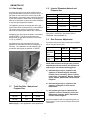
1.1
Model Numbers, Net Weights and
Dimensions
MODEL,
TDH - 20
TDH - 40
WIDTH mm (in)
610 (24.0)
685 (26.9)
DEPTH mm (in)
800 (31.5)
830 (32.6)
HEIGHT mm (in)
645 (25.4)
725 (28.5)
WEIGHT kg (lbs)
98 (215)
110 (240)
1.2
CAUTION
THE APPLIANCE FLUE DISCHARGES
VERTICALLY FROM THE TOP OF THE UNIT AT
THE REAR. IT MUST NOT BE DIRECTLY
CONNECTED TO ANY FLUE, MECHANICAL
EXTRACTION SYSTEM, OR DUCTING LEADING
OUTSIDE THE BUILDING. THE APPLIANCE IS
BEST DISCHARGED UNDER AN OPEN CANOPY
WHICH CONNECTS WITH A VENTILATING
SYSTEM.
Siting
Equipment
The appliance should be installed on a level table
top in a well lit and draught free position. The
installation of the appliance must be executed in
accordance with local and/or national regulations
as listed in this manual.
1.3
Clearances
Minimum clearances of 150 mm (5.9 in) from the
sides of the appliance and 250 mm (9.8 in) from
the rear of the appliance are required if the
appliance is installed next to combustible surfaces.
A vertical clearance of 750 mm (29.6 in) minimum
should be allowed between the top rim of kettle
and any overlying surface.
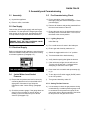
1.4
m3 / min
ft3 / min
Units Type
Range
17
600
Pastry Oven
17
600
Fryer
26
900
Grill
17
600
Steak Grill
26
900
Boiling Pan
17
600
Steamer
17
600
Sterilizing Sink
14
500
Bains Marie
11
400
Tea/Coffee
Machine
8.5-14
300-500
1.5
Ventilation
Ventilation Rate Required
Electrical Supply
This unit is designed for connection to fixed wiring.
A suitably rated isolating switch with contact
separation of at least 3 mm (0.12 in) on both poles
must be fitted to the installation. The wiring must be
executed in accordance with the regulations listed in
this manual.
The unit must be installed in an adequately
ventilated room with provision for an adequate air
supply to the unit. The area directly around the
appliance must be cleared of combustible material.
For multiple installations, requirements for
individual appliances should be added together.
Installation should be made in accordance with
local and/or national regulations applying at the
time. A competent installer must be employed.
Cable entry is at the lower rear on right side of the
appliance. Access to the terminals is gained by
removing relevant panels. (Paragraphs 3.5.1 and
3.5.2)
Recommendations for ventilation for catering
appliances are given in BS 5440:2 and are shown
in the following table.
Provide 230 VAC, 50 Hz, 1 Phase, 1 Amp or 40
Watts. The electrical schematic is located in the
service compartment and in this manual.
WARNING
THIS APPLIANCE MUST BE EARTHED.
5
OM/SM-TDH-CE
1.8
1.6 Gas Supply
Incoming gas service must be of sufficient size to
supply full rate without excessive pressure drop. A
gas meter is connected to the service pipe by the
Gas Supplier. Any existing meter should be checked
by the Gas Supplier to ensure that it has capacity to
pass the required rate of gas for the kettle in addition
to any other gas equipment installed.
The appliance governor is incorporated in the gas
control valve which is situated in the control cabinet.
The control valve governor is suitable for both
natural and propane gases without any conversion.
Injector Diameters-Natural and
Propane Gas
Injector
TDH-20
TDH-40
G20 Nat. Gas
0.94 mm
1.09 mm
No. of Orifices
8
12
G25 Nat. Gas
1.09 mm
1.19 mm
No. Of Orifices
8
12
G31 Propane
Gas
0.57 mm
0.66 mm
No. of Orifices
8
12
Pilot Orifice : NATURAL - Honeywell CAR 24;
PROPANE -Honeywell BBR 10
Installation pipe work should be fitted in accordance
with IEGE/UP/2. The pipe work should not be
smaller than the gas inlet connection on the kettle,
i.e. Rp ½ (½”BSPT).
1.9
Gas Pressure Adjustment
A pressure test point is fitted on the burner manifold
and on the gas control valve.
An isolating cock must be located close to the
appliance to allow shut off during an emergency or
servicing. The installation must be tested for gas
soundness and purged as specified in IGE/UP.
TDH-20
TDH-40
G20, G25 mbar
NATURAL
in. w.c.
GAS
8.75
8.75
3.5
3.5
G31
mbar
PROPANE
in. w.c.
GAS
25
25
10
10
NOTE: With reference to the gas rate, pressure
adjustments and conversions, this appliance is
approved for use with the following gases:
a) G20 natural gas may be supplied to the
appliance in Austria, Belgium, Denmark,
Finland, France, Germany, Greece, Iceland,
Ireland, Italy, Luxembourg, Norway, Portugal,
Spain, Sweden, Switzerland and the United
Kingdom.
1.7
b) G25 natural gas may be supplied to the
appliance in Belgium, France and the
Netherlands.
Total Gas Rate - Natural and
Propane Gas
Model
Kw
BTU/hr
TDH-20
8.2
28,000
TDH-40
14.3
48,800
c) G31 propane gas may be supplied to the
appliance in France, Germany, Ireland, the
Netherlands, Portugal, Spain, Switzerland
and the United Kingdom.
Use of the appliance with non-approved gases in a
listed country, or use in other countries will void CE
certification.
Water Supply — Not applicable to these appliances.
6
OM/SM-TDH-CE
2. Assembly and Commissioning
2.1 Assembly
2.5
a) Unpack the appliance
a) Prior to operation, clean out kettle pan
thoroughly using hot water and detergent. Rinse
pan thoroughly.
b) Place on a firm, level table.
Pre-Commissioning Check
2.2 Gas Supply
b) Remove all literature and packing materials from
the interior and exterior of the unit.
Connect the unit to the gas supply and test for gas
soundness. For that part of the integral gas supply
down stream of the gas valve, leak detection spray
or soap solution may be used with the burners lit.
c) Ensure the open end or the elbow at the outlet of
the safety valve is directed down. If it is not, turn
the elbow to the correct position.
2.5.1 Lighting Sequence
CAUTION
ENSURE THAT THE PAN CONTAINS LIQUID
WHEN THE BURNERS ARE ALIGHT.
Initial Start Up:
a) Put a small amount of water in the kettle pan.
2.3 Electrical Supply
b) Ensure gas and electricity mains are on.
Before commissioning the appliance, ensure that the
electrical installation has been carried out according
to relevant regulations. (Paragraph 1.5.).
c) Switch the toggle switch to the "on" position.
d) Turn thermostat dial to desired setting.
e) Verify that the spark igniter lights the burners.
f)
WARNING
THIS APPLIANCE MUST BE EARTHED.
2.4
If the unit does not light, the unit will lock-out.
Turn the unit off and wait 1-2 minutes before
attempting to switch the unit on again.
g) Press reset lock-out switch and repeat steps (b)
to (e).
Jacket Water Level/Jacket
Pressure
h) To turn the unit off, switch toggle (On/Off) switch
to the “Off” position.
i)
a) Ensure that the jacket water level is correct by
confirming that the level is in the middle of the
sight glass. If the water is low, follow the
instructions under "Jacket Filling" (Paragraph
3.3).
Turn gas and electricity mains off.
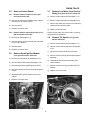
2.5.2 Setting The Gas Pressure
a) It is necessary to check the gas pressure during
commissioning. A suitable pressure gauge must
be connected to the pressure test point on the
gas control valve or the gas manifold. See below
for test points on the gas control valve.
b) Check the pressure gauge. If the gauge does not
show 20 or more inches of vacuum (that is, a
reading of 20 to 30 below zero) see "Jacket
Vacuum" (Paragraph 3.2).
7
OM/SM-TDH-CE
i)
Disconnect the pressure gauge from the test
point.
j)
Re-seal the pressure test point and test for gas
soundness. Replace in reverse order.
2.5.3 Checking Performance of Controls
a) Light the unit as described in Paragraph 2.5.1.
Check that the controls produce a healthy spark
from the electrode to the earthing post and
ignition is smooth and without delay.
b) Turn thermostat off and then on. Check that
burners go out when the thermostat is switched
off and then ignite smoothly and without delay
when switched back on. Repeat several times.
When checking pressure at test points on the gas
valve, undo the screw a half turn and slip tube over
nipple.
c) If the unit fails to respond as detailed above it
should be serviced by an authorized Groen
service agent.
b) Turn the gas and electricity mains on.
c) Light the burners (Paragraph 2.5.1).
2.6
Important
After installing and commissioning the
appliance, the user's instructions should be
handed to the user or purchaser. Ensure that
instructions for lighting, turning off, correct use
and cleaning are properly understood. Emphasis
should be made with regard to the location of the
main gas isolating valve and the emergency
shut-down procedure should be demonstrated.
d) Remove control cabinet lid (Paragraph 3.5.1).
e) Remove control cabinet side panel (Paragraph
3.5.2).
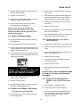
f)
Instruction to User
Remove governor cap screw on gas control
valve. See figure below for position.
g) Governor is suitable for natural or propane gas.
h) To increase pressure turn screw inside the
governor turret clockwise or anti-clockwise to
reduce pressure. Check the burner pressure
again after 15 minutes of operation and adjust if
necessary.
8
OM/SM-TDH-CE
3. Servicing and Conversion
on the gear housing until grease flows out of the
bearings around the shaft. Put a liberal amount of
grease on the gear to cover the arc of contact with
the gear.
Important
Before attempting any servicing, ensure that the
gas isolating cock is turned off and cannot be
inadvertently turned on. Disconnect the
electricity supply.
Safety Valve
At least twice monthly the safety valve requires
checking to ensure that it works correctly. With the
gauge pressure at about five PSIG, lift the valve level
enough to vent steam, then quickly let it snap back
into place.
After any maintenance task, check the appliance
to ensure that it performs correctly. Carry out
necessary adjustments as detailed in Section 1.
After any servicing or exchange of gas carrying
components:
ALWAYS CHECK FOR GAS SOUNDNESS
NOTE: When replacing wiring connections refer to
the wiring diagram contained on the unit and in this
manual.
WARNING
AVOID ANY EXPOSURE TO THE STEAM
BLOWING OUT OF THE SAFETY VALVE.
After Servicing
a) Test for gas soundness as specified in IGE/UP1
as appropriate after any gas connection has
been disturbed.
This procedure should be explained to the user,
since it is to be carried out at least twice a month.
Relevant safety procedures and requirements should
also be explained to the user when carrying out the
procedure.
b) Check for correct operation, as appropriate (see
commissioning of appliance).
3.1
Regular Servicing Procedures
Conversion
See Paragraphs 1.8 and 1.9 for important
information about gas conversion. Verify the
type of gas to be used. All conversions must be
for approved gas in countries listed in Paragraph
1.9.
The following must be serviced at regular intervals.
Burners
The burner should be cleaned periodically to
maintain maximum performance. Burners are best
cleaned with a wire brush. Any blocked parts are
best cleaned with a metal broach, taking care not to
damage the burner head.
To change from natural gas to propane gas or vice
versa change
Burner Injector
Pressure Setting
Data Plate
Pilot Orifice
The injector orifice should be cleaned with a wooden
splinter. Metal reamers could distort or increase the
orifice size and should be avoided.
Gears
The governor spring does not require changing, only
the pressure setting.
The gear housing has fittings for lubrication of
moving parts. Because the gears do not run in oil,
periodic lubrication with grease is necessary.
Lubrication frequency depends on operating
conditions, but should be performed at least once
every six months. A #2 grade LGI lithium grease is
recommended. Add grease through the Zerk fittings
IMPORTANT
This appliance was fitted with gas injectors for
type G20 natural gas at the factory. Injectors for
type G25 natural gas are shipped as an
accessory. Prior to installing equipment, or
when converting to another gas, verify that the
injector gas size marking on the injector matches
9
OM/SM-TDH-CE
filling must be removed to obtain efficient heating
(Paragraph 3.2).
information on the data plate for the type of gas
being used.
3.2
Jacket Vacuum
CAUTION
TDH STEAM JACKETED KETTLES ARE
DESIGNED TO USE TREATED, DISTILLED
WATER ONLY. USE OF ANY OTHER WATER
CAN CAUSE LIME ACCUMULATION ON
INTERNAL SURFACES, AND WILL VOID ALL
WARRANTIES.
When the kettle is cold, a positive reading or a
reading near zero on the pressure vacuum gauge
indicates excess air in the jacket. Air in the jacket
slows down kettle heating.
To remove air:
3.4
a) Light the unit (Paragraph 2.5.1).
b) When the pressure/vacuum gauge reaches a
positive pressure reading of five PSIG, release
entrapped air and steam by lifting the lever on
the safety valve for about one second. Repeat
this a few times. Let the valve snap back into the
closed position.
Water Treatment Procedure
WARNING
READ AND FOLLOW ALL PRECAUTIONS
STATED ON THE WATER TREATMENT
COMPOUND LABEL TO AVOID INJURY.
a) Fill the mixing container with the measured
amount of water required (See Table below).
Use distilled water only.
b) Hang a strip of pH test paper on the rim of the
container, with about 1"(25 mm) of the strip
below the water surface.
WARNING
AVOID ANY EXPOSURE TO THE STEAM
BLOWING OUT OF THE SAFETY VALVE.
c) Measure the water treatment compound (e.g.,
add the compound to the water from a small
measuring cup).
d) Stir the water continuously while you slowly add
water treatment compound, until the water
reaches a pH between 10.5 and 11.5. Judge the
pH by frequently comparing the color of the test
strip with the color chart provided in the pH test
kit.
3.3 Jacket Filling
The jacket has been charged at the factory with the
proper amount of treated, distilled water. You may
need to restore jacket water to its proper level, either
because water was lost as steam during venting or
by draining.
e) Record the exact amounts of water and
treatment compound used. These amounts may
be used again if the same sources of water and
compound are used in the future. However, it is
advisable to check the pH every time water is
prepared. For optimum performance, use
correctly treated distilled water.
To add water:
a) If you are replacing water lost as steam use
distilled water. If you are replacing treated water
that ran out of the jacket, prepare more treated
water (Paragraph 3.4).
b) Let the kettle cool completely. Turn the safety
valve elbow anti-clockwise (to avoid thread
damage) until it faces upward.
Model
c) Open the globe valve and pour distilled or
treated water into the elbow inlet.
d) Hold the safety valve open while you pour to let
air escape from the jacket. Air introduced during
10
Kettle Capacity Jacket Capacity
TDH-20
18.9 Litres
6.6 Litres
TDH-40
37.9 Litres
8.5 Litres
OM/SM-TDH-CE
3.5
3.7
Remove Control Panels
3.5.1 Remove Control Cabinet Lid (Turn gas
and electric mains off)
Remove Low Water Level Control
Relay (Turn gas and electric mains off)
a) Remove control cabinet lid (Paragraph 3.5.1).
a) Remove the 2 screws around the edge of the lid
securing it to the control cabinet.
b) Remove cabinet side panel (Paragraph 3.5.2).
b) Remove the lid.
c) Remove low water level control from its base by
undoing the two retaining clips.
c) Replace in reverse order.
d) Replace in reverse order.
3.5.2 Remove Control Cabinet Side Panel (Turn
gas and electric mains off)
Ensure the low water level control relay is correctly
oriented when re-positioned.
a) Remove lid (Paragraph 3.5.1).
3.8
electric mains off)
b) Remove the four screws securing the side panel
to the control cabinet.
a) Remove control cabinet lid (Paragraph 3.5.1).
c) Remove panel.
b) Remove control cabinet side panel (Paragraph
3.5.2).
d) Replace in reverse order.
3.6
Remove Tilt Switch (Turn gas and
c) Disconnect electrical leads from tilt switch.
Remove Spark Ignition Module
(Turn gas and electric mains off)
d) Remove screws securing the tilt switch bracket
assembly.
a) Remove control cabinet lid (Paragraph 3.5.1).
b) Remove cabinet side panel (Paragraph 3.5.2).
e) Withdraw tilt switch bracket assembly from
control cabinet.
c) Disconnect leads from spark ignition module.
f)
d) Remove retaining screws securing spark ignition
module.
g) Replace in reverse order.
e) Withdraw spark ignition module from control
cabinet.
f)
Replace in reverse order.
11
Remove screws securing the switch from the
bracket.
OM/SM-TDH-CE
3.9
e) Withdraw the neon from the control cabinet.
Remove Gas Control Valve (Turn
gas and electric mains off)
f)
a) Remove control cabinet lid (Paragraph 3.5.1).
Replace in reverse order.
3.12 Remove Thermostat (Turn gas and
electric mains off)
b) Remove control cabinet side panel (Paragraph
3.5.2).
a) Remove panel from kettle base by undoing the
retaining screws.
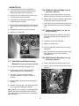
c) Tilt kettle until the burners are fully exposed and
disconnect the pilot assembly from the burner
guard.
b) Drain kettle by tilting it slightly and undoing Phial
Boss connection. Allow kettle to drain into a
suitably sized container.
d) Remove the nuts securing the burner guard to
the appliance base and remove the burner
guard.
e) Undo the union fittings on either side of the
control valve and disconnect the electrical leads
from the control valve.
f)
Remove control valve from control cabinet.
WARNING
ENSURE THAT ELECTRICAL LEADS AND
CONNECTIONS IN THE KETTLE BASE DO NOT
GET WET. REMOVE IF REQUIRED.
g) Replace in reverse order.
3.10 ON/OFF Switch and Reset Button
(Turn gas and electric mains off)
Important:- Retain drained water from kettle
jacket. The jacket was charged at the factory with
the correct amount of treated distilled water.
This water should be used to refill the kettle.
However, if water is lost during drainage see
Paragraph 3.3, Jacket Filling.
a) Remove control cabinet lid (Paragraph 3.5.1).
b) Remove cabinet side panel (Paragraph 3.5.2).
c) Disconnect electrical leads from the On/Off
switch or reset button.
c) Remove thermostat control knob and disconnect
electrical leads.
d) Undo and remove retaining collar securing the
On/Off switch to the control cabinet outer
surface, and securing the reset button to the
inner surface of the control cabinet.
d) Undo and remove thermostat retaining screws
which hold the thermostat to the kettle base
control compartment.
e) Withdraw the On/Off switch or reset button as
required.
f)
Replace in reverse order.
3.11 Remove Neons (Turn gas and electric
mains off)
a) Remove control cabinet lid (Paragraph 3.5.1).
b) Remove cabinet side panel (Paragraph 3.5.2).
c) Disconnect the electrical leads to the neon.
d) Undo and remove the retaining collar which
secures the neon to the control cabinet.
12
OM/SM-TDH-CE
e) Remove thermostat phial from kettle base and
withdraw the thermostat.
b) Disconnect the electrical leads from the water
level sensor.
f)
c) Drain the kettle by tilting the kettle slightly and
undoing the low water level sensor. Allow the
kettle to drain into a suitably sized container.
Replace in reverse order.
g) Ensure an adequate sealant is used to seal the
replacement thermostat Phial Boss.
d) Remove the low water level sensor from the
kettle base.
h) Once the thermostat is in place, the jacket
should be refilled. (Paragraph 3.3).
e) Replace in reverse order
Always refer to the wiring diagram when
reconnecting electrical leads. The wiring
diagram is located inside the appliance and at
the rear of this manual.
f)
Ensure a suitable sealant is used to seal the low
water level sensor Boss.
g) Once the low water level sensor is in place, the
jacket should be filled (Paragraph 3.3).
3.13 Remove Pressure Switch
a) Remove panel from base of kettle by undoing
the retaining nut.
3.15 Remove Burners (Turn gas and
b) Disconnect pressure switch electrical leads.
a) Tilt the kettle until the burners are fully exposed.
c) Remove the microswitch and retaining bracket.
This will allow the pressure sensor section to be
removed from the kettle base.
b) Disconnect the pilot assembly from the burner
guard.
electric mains off)
c) Remove the retaining nuts securing the burner
guard to the appliance base.
d) Allow the kettle to drain by undoing the pressure
switch connection in the kettle base. Drain into a
suitably sized container.
d) Remove the burner guard.
e) The burners are now accessible and can be
removed as required.
f)
g) Ensure adequate sealant is used to seal the
burners.
WARNING
ENSURE THAT ELECTRICAL LEADS AND
CONNECTIONS IN THE KETTLE BASE DO
NOT GET WET. REMOVE IF REQUIRED
ALWAYS CHECK FOR GAS SOUNDNESS WHEN
ANY PART OF THE GAS CIRCUIT HAS BEEN
DISTURBED.
e) Remove and withdraw the pressure sensor
section from the kettle base.
f)
Replace in reverse order.
3.16 Remove Pilot Assembly/Pilot
Injector (Turn gas and electric mains
Replace in reverse order.
off)
g) Once the pressure switch is in place, the jacket
should be refilled (Paragraph 3.3).
a) Undo pilot pipe compression fitting.
b) Remove pilot pipe from pilot assembly
3.14 Remove Low Water Level Sensor
(Turn gas and electric mains off)
c) If the pilot injector is to be changed, it may be
done at this stage. Remove the pilot injector
from the pilot assembly. Change, clean or
replace as required.
a) Remove panel from base of kettle by undoing
the retaining screws.
13
OM/SM-TDH-CE
d) If the pilot assembly is to be removed then
remove the flame sensing electrode wire (HT
lead) from the flame sensing electrode.
3.18 Remove Pressure Gauge (Turn gas
and electric mains off)
a) Using the correctly-sized spanner, remove the
pressure gauge from the kettle jacket pipework.
e) Remove the two retaining screws securing the
pilot assembly to the burner guard.
f)
b) Replace with new pressure gauge ensuring that
an adequate sealing compound is used.
Withdraw the pilot assembly from the burner
guard/combustion chamber.
c) Once the pressure gauge has been replaced the
kettle jacket will need to be vented. (Paragraph
3.2).
g) Disconnect the spark electrode HT lead from the
ignition module and feed through control cabinet
wall.
h) Withdraw pilot assembly from the appliance.
i)
3.19 Remove Sight Glass (Turn gas and
electric mains off)
Replace in reverse order.
a) Undo the sight glass and allow the contents of
the kettle jacket to drain into a suitably sized
container.
b) Completely remove the sight glass.
c) Replace in reverse order.
d) Ensure an adequate sealant is used to seal the
sight glass.
e) Once the jacket has been drained and the sight
glass replaced, the jacket will need filling
(Paragraph 3.3).
3.20 Multi-Function Gas Valve (Turn gas
and electric mains off)
3.17 Spark Electrode/Flame Sensing
Bracket (Turn gas and electric mains off)
a) Remove the elbow from the gas control valve.
a) Remove pilot assembly (Paragraph 3.16).
b) Remove the gas control valve from kettle jacket
pipework.
b) Undo retaining screws securing the flame
sensing electrode to the pilot assembly.
c) The spark electrode is fitted to the pilot
assembly, therefore a new pilot assembly is
required.
d) Replace spark electrode and pilot assembly as
required.
e) Replace in reverse order. The spark gap should
be pre-set with no adjustment required.
Note: After fitting, ensure there is an adequate spark
between the pilot shroud and the spark electrode.
Also ensure that the sensing electrode is positioned
in the pilot flame.
14
OM/SM-TDH-CE
c) Replace in reverse order.
d) Ensure an adequate sealing compound is used
to seal the gas control valve.
3.22 Fuse Replacement (Turn gas and
3.21 Filling Valve (Turn gas and electric
a) Remove control cabinet lid (Paragraph 3.5.1).
electric mains off)
mains off)
a) Remove filling valve from kettle jacket pipework.
b) Remove control cabinet side panel (Paragraph
3.5.2).
b) Replace in reverse order.
c) Remove fuse from vertical fuse holder.
c) Ensure adequate sealing compound is used to
seal the valve.
d) Replace fuse (identical to fuse removed).
e) Replace in reverse order.
d) Once the safety fill is replaced the jacket will
need to be vented (Paragraph 3.2).
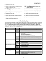
4. Troubleshooting
Your Groen kettle is designed to operate smoothly and efficiently if properly maintained. However, the following
are checks to make in the event of a problem. Wiring diagrams are inside the service panel and in the back of
this manual. USE OF ANY REPLACEMENT PARTS OTHER THAN THOSE SUPPLIED BY GROEN OR
THEIR AUTHORIZED DISTRIBUTORS CAN CAUSE INJURY TO THE OPERATOR AND DAMAGE TO THE
EQUIPMENT AND WILL VOID ALL WARRANTIES.
SYMPTOM
WHO
WHAT TO CHECK
Kettle is hard to tilt.
Auth
Service
Rep Only
a. Gears for foreign materials, lubrication, and alignment
Burners will not light.
User
a. That the main gas supply cock is open (handle is in line with
the gas pipe.)
b. Gas supply to the building.
c. That the kettle body is not tilted.
d. That electric power supply to the unit is on.
Auth
Service
Rep Only
e. Thermostat operation.
f. That the tilt limit switch is closed, when the kettle body is not
tilted.
Kettle continues heating after
it reaches the desired
temperature
User
a. Thermostat dial setting.
Auth
Service
Rep Only
b. Thermostat calibration.
c. Thermostat operation.
Kettle stops heating before it
reaches the desired
temperature.
User
a. Thermostat dial setting.
Auth
Service
Rep Only
b. Thermostat calibration.
c. Thermostat operation.
Kettle heats slowly.
User
a. For air in jacket (Paragraph 3.2).
Safety valve pops.
User
a. For air in jacket (Paragraph 3.2).
Auth
Service
Rep Only
b. Safety valve. If valve pops at pressures below 49 PSIG,
replace it.
c. If high limit pressure switch is set too high.
d. Thermostat operation
15
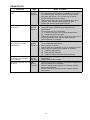
OM/SM-TDH-CE
SYMPTOM
WHO
WHAT TO CHECK
System does not produce a
spark.
Auth
Service
Rep Only
a. Thermostat, and close the contacts, if they are open.
b. AC voltage between terminals “1" and GND. If it is not 230
VAC, check the high limit switch, which should be closed
c. Pilot spark gap. Regap, if it is not 7/64 inch (2.78 mm).
d. Electrode ceramic for crack or break.
e. That the high tension cable is firmly attached and in good
condition. If it is cracked or brittle, replace the pilot.
f. Replace the electronic spark ignition module.
Spark is present, but the pilot
will not light.
Auth
Service
Rep Only
a. That the gas valve is opening.
b. That gas pressure meets the control manufacturer’s
specifications.
c. For gas at the pilot. If it is not flowing:
(1) Check the pilot gas line for kinks and obstructions.
(2) Replace the gas control valve.
d. That the pilot spark gap is 7/64 inch (2.78 mm) and located in
the pilot gas stream. If not, adjust or replace the pilot.
e. Orifice, and clean, if necessary
Pilot lights, but main burner
will not come on, and the
spark stays on.
Auth
Service
Rep Only
a. Sensor cable, to make sure of secure attachment to terminal
“1" on module and to the sensor.
b. Sensor ceramic for cracks.
c. That the cable is not grounded out. If it is, correct the ground.
d. Sensor cable for continuity and condition of insulation.
e. (1) Check the gas pressure.
(2) Clean the pilot assembly.
(3) Tighten mechanical and electrical connections.
Pilot lights, but main burner
will not come on, and spark
does not stay on.
Auth
Service
Rep Only
a. That gas pressure meets the control manufacturer’s
specifications.
b. Replace spark ignition module.
Main burner comes on but will Auth
not stay lit.
Service
Rep Only
a. Check burner ground for bad wire or connection. Replace with
high temperature wire if necessary.
b. Check for low gas supply pressure. If necessary, replace
ignition control module.
c. Ceramic insulator or pilot flame sensor cracked. Replace
flame sensor.
16
OM/SM-TDH-CE
5. User Instructions
Regulations and Safety Precautions
These Appliances have been CE marked on the
basis of compliance with the Gas Appliance
Directive, EMC and Low Voltage Directive for the
Countries, Gas Types and Pressures as stated on
the Data Plate.
WARNING
TO PREVENT SHOCKS, ALL APPLIANCES
WHETHER GAS OR ELECTRIC, MUST BE
EARTHED.
These appliances MUST BE installed by a
competent person in conformity with the
INSTALLATION AND SERVICING
INSTRUCTIONS and National Regulations in
force at the time.
Upon completion of the installation, the Owners
Manual should be handed to the users. Tthe
installer should instruct responsible person(s) on
the correct operation and maintenance of the
Appliance. This equipment is ONLY FOR
PROFESSIONAL USE, and shall be operated by
QUALIFIED persons. It is the responsibility of the
Supervisor or equivalent to ensure that users
wear SUITABLE PROTECTIVE CLOTHING and
to draw attention to the fact that, some parts will,
by necessity, become VERY HOT and will cause
burns if touched accidentally.
Particular attention MUST be paid to the
following:
I.E.E. Regulations for Electrical Installations
Electricity at Work Regulations
Gas Safety (Installation & Use) Regulations
Health and Safety at Work Act
Fire Precautions Act
Local and National Building Regulations
IMPORTANT - READ FIRST - IMPORTANT The
Groen Steam Jacketed Kettle you have just
purchased has been handcrafted from the finest
materials, meticulously inspected, and carefully
tested to ensure that you receive the best
possible product. With reasonable care and
maintenance, it will provide years of faithful
service. It is recommended that you establish a
timetable for periodic maintenance as outlined in
this manual. Log space has been provided in this
manual. Keep it up-to-date and on file.
Furthermore, if a need arises to convert the
Appliance for use with another gas, a competent
person must be consulted. Those parts which
have been protected by the manufacturer MUST
NOT be adjusted by the User.
Users should be conversant with the appropriate
provisions of the Fire Precautions Act and the
requirements of the Gas Safety Regulations. In
particular the need for regular servicing by a
competent person to ensure the continued safe
and efficient performance of the Appliance.
17
OM/SM-TDH-CE
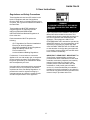
5.1 Equipment Description
5.1.1 General
5.1.2 Available Options
Groen model TDH are stainless steel, steam
jacketed, table-top mounted, tilting kettles with a
self-contained, gas-heated steam source. The kettle
body is welded into one piece and furnished with a
reinforced bar rim and welded "butterfly" pouring lip.
The interior of the kettle is polished to a 180 emery
grit finish, and the exterior is given a bright
semi-deluxe finish. The unit is ASME shop inspected
and registered with the National Board for working
pressures up to 50 PSIG. Kettle support, tilting
mechanism, and controls are contained in an
enclosed compartment resting on a base plate.
Tilting is provided by a self-locking, worm-and-gear
device, or a pull tilt handle.
Options available with listed models include:
a) One piece, lift-off cover.
b) Basket inserts.
c) Stand that supports the unit and holds a pan in
position for filling.
d) Fill faucet with swing spout.
e) Kettle Brush Kit.
5.1.3 Operational and Maintenance Safety
The self-contained steam source is heated by
propane or natural gas and ignition is by electronic
spark.
WARNING
INSTALLATION OF THE UNIT MUST BE DONE
BY PERSONNEL QUALIFIED TO WORK WITH
ELECTRICITY AND PLUMBING IN
ACCORDANCE WITH ALL APPLICABLE CODES.
Charged at the factory with treated, distilled water,
the steam source provides kettle temperature of
65oC to 150oC. Controls include a thermostat,
pressure gauge, gauge glass, safety valve, pressure
limit control, low water cut-off, on/off switch and a
multi-functional gas control valve.
BEFORE REPLACING ANY PARTS,
DISCONNECT THE UNIT FROM THE ELECTRIC
POWER SUPPLY AND CLOSE THE MAIN GAS
COCK. ALLOW FIVE MINUTES FOR UNBURNED
GAS TO VENT.
The gas supply shuts off automatically when the
kettle is tilted.
TO PREVENT SHOCKS, ALL APPLIANCES
WHETHER GAS OR ELECTRIC, MUST BE
EARTHED.
Service connections are required for gas and 230-V,
single phase, 50 Hz electricity.
CAUTION
OPERATORS MUST READ, UNDERSTAND AND
FOLLOW CAUTIONS AND SAFETY AND
OPERATING INSTRUCTIONS CONTAINED IN
THIS MANUAL.
Important:
Prior to operation, clean out the kettle pan
thoroughly using hot water and detergent. Rinse
out and dry thoroughly.
The gas burners are protected by an electronic
flame failure device which incorporates
automatic ignition of the burners and instant
shut-off of the gas supply to the burners should
a gas supply interruption occur.
18
OM/SM-TDH-CE
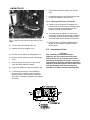
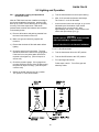
5.2 Lighting and Operation
g. Turn the thermostat dial to the required setting.
5.2.1 Initial Kettle Lighting and Operational
Readiness Check
h. After 10-15 seconds the burners should light.
The "heat on" neon will illuminate.
After the TDH Kettle has been installed according to
service and installation instructions, perform initial
start-up as a test to ensure that the unit is operating
correctly. Follow the steps below. TDH steam
jacketed kettle controls and indicators are identified
in the drawing below.
i.
a) Remove all literature and packing material from
the interior and exterior of the unit.
In the event the burners do not light, or go out as
indicated by the illumination of the lockout
indicating neon, turn the unit off. Wait
approximately one minute. Press lockout reset
switch and repeat steps (f) to (g).
WARNING
AVOID CONTACT WITH FLUE. SURFACES ARE
VERY HOT AND WILL CAUSE BURNS.
b) Make sure gas and electricity supplies are
turned on.
DO NOT OBSTRUCT FLUE EXHAUST OPENING.
c) Ensure that the kettle is filled with water before
lighting.
5.2.2 To Shut Down Kettle
d) Check the water level in the jacket. The level
should be between the lines on the gauge glass.
If the level is low, the jacket water level will be
required to be topped up. (This will require a
service call).
a. Turn the thermostat dial to the “Off” position
b. Turn the On/Off switch to the “Off” position
c.
e) Check the pressure gauge. If the gauge does
not show sufficient vacuum (20 to 30 below zero)
the jacket will require venting. (This will require
a service call).
f)
For a prolonged shut down:
Follow steps a and b. Turn off the gas and
electricity mains.
Switch the On/Off switch to the "On" position.
The “power on” neon will illuminate.
19
OM/SM-TDH-CE
d) Tilt cut-off switch that shuts off all burners when
the kettle is tilted.
5.2.3 Filling the Kettle
Prior to operating the unit, clean out the kettle pan
thoroughly, using hot water and detergent.
When the kettle reaches the set temperature, the
thermostat switch opens, stopping the signal to the
gas control valve and causing the valve to shut off
all gas flow. When the kettle cools below the set
temperature, the thermostat switch closes and
starts another heating cycle. On-off cycling
continues and maintains the kettle at the desired
temperature.
Kettle capacities:
Model
Kettle Capacity
TDH-20
18.9 Litres
TDH-40
37.9 Litres
These are maximum capacities. To prevent surge
boiling, no more than 80% of the maximum capacity
should be used during operation.
5.2.6 To Empty Kettle
5.2.6.1
Crank Tilt Models: To tilt the body of the
kettle forward, turn the hand crank on the
front of the cabinet anti-clockwise. The
body will stay in the position when you stop
turning the handle. To return the body to
the upright position, turn the crank
clockwise.
5.2.6.2
Pull Tilt Models: The kettle is designed to
be tilted in a controlled manner. Grasp the
insulated plastic ball firmly. Maintain a firm
grip on the handle when tilting, while
keeping the kettle body in a tilted position,
and when slowly returning the kettle body
to an upright position.
5.2.4 User’s Thermostat
Provides automatic control of the Kettle Jacket
temperature at selected settings to a maximum of
147oC.
5.2.5 Sequence of Operation
The following "sequence of operation" outline is
provided to help the user understand how the unit
functions.
When the operator sets a temperature on the
thermostat dial, the thermostat switch closes and
sends a signal which (1) starts the spark and (2)
opens the automatic valve for the burners.
The spark ignites the burner on low flow. The flame
completes a circuit at the sensing probe and sends
a signal that causes the spark to shut off and the
automatic valve to open to full flow once a flame
has been detected. If a flame is not detected within
15 seconds the gas is automatically cut-off and the
appliance is locked-out. The unit can only be re-lit
once the reset button has been pressed.
WARNING
DO NOT STAND IN FRONT OF THE KETTLE
BODY WHEN TILTING IT. BE CAREFUL TO
KEEP HOT CONTENTS FROM SPILLING.
ENSURE PEOPLE ARE KEPT AWAY FROM THE
KETTLE WHEN EMPTYING IT.
In addition to the lockout timer, safety features
include:
5.2.7 Power Failure
a) Low-water cut-off relay that will shut off the gas
supply to all burners until the water level is
corrected.
If the power to the unit fails, do not attempt to
operate the appliance until the electricity supply is reestablished.
b) High pressure switch, set to open at about 46
PSIG and shut down the burners until jacket
pressure is decreased.
When the power comes back on, follow the steps in
Initial Kettle Lighting and Operational Readiness
Check (Paragraph 5.2.1).
c) Pop safety valve, which will release steam if the
jacket pressure exceeds 50 PSIG. See detailed
Instructions pertaining to Safety Valve
installation and operation. (Paragraphs 3.2 and
3.20)
20
OM/SM-TDH-CE
5.3 Cleaning and Maintenance
f) To remove materials stuck to the equipment,
use a brush, sponge, cloth, plastic or rubber
scraper, or plastic wool with the detergent
solution. To minimize the effort required in
washing, let the detergent solution sit in the
kettle and soak into the residue, or heat the
detergent solution briefly.
IMPORTANT
Disconnect the electricity supply before any
cleaning is undertaken. The appliance must not
be cleaned with a jet of water nor should it be
steam cleaned.
5.3.1 Suggested Tools
g) Do not use any abrasive materials or metal
implement that might scratch the surface.
Scratches make the surface hard to clean
and provide places for bacteria to grow. DO
NOT use steel wool, which may leave
particles imbedded in the surface and cause
eventual corrosion and pitting.
a) Detergent and sanitizing agent, or a
combination cleaning - sanitizing agent.
b) Kettle brushes, long handled and short handled.
5.3.2 Precautions
Before cleaning operation, shut off the burner by
turning the thermostat dial to "OFF". If water or
cleaning/sanitizing solution will be sprayed, shut off
all electric power to the unit at a remote switch such
as the circuit breaker.
h) The exterior of the unit may be polished with
a recognized stainless steel cleaner or with
hot water and detergent.
WARNING
KEEP WATER AND SOLUTIONS OUT OF
CONTROLS, GEARS, BURNERS, ETC. NEVER
SPRAY OR HOSE THE CONTROL CONSOLE,
ELECTRICAL CONNECTIONS, TILTING
MECHANISM OR CABINET.
5.3.3 Procedure
a) Clean all food contact surfaces as soon as
possible after use, preferably while the kettle
is still hot. If the unit is in continuous use,
thoroughly clean and sanitise both interior
and exterior at least once every 12 hours.
Use a brush, cloth, sponge or other nonabrasive tool for cleaning.
b) Scrape and flush out large amounts of food
residues. Be careful not to scratch the kettle
with metal implements.
c) Prepare a hot solution of the
detergent/cleaning compound as instructed
by the supplier. Clean the unit thoroughly. A
cloth moistened with cleaning solution can
be used to clean controls, control housings
and electrical conduit.
d) Rinse the kettle thoroughly with hot water,
then drain completely.
e) As part of the daily cleaning program, clean
all external and internal surfaces that may
have been soiled. Remember to check such
parts as the underside of the kettle and
control housing.
Don’t use metal implements or steel wool.
21
OM/SM-TDH-CE
i)
When the equipment needs to be sanitized,
use a sanitizing solution equivalent to one
that supplies 200 parts per million available
chlorine. Obtain advice on the best sanitizing
agent from your supplier of sanitizing
products. Following the suppliers
instructions, apply the sanitizing agent after
the unit has been cleaned and drained.
Rinse off the sanitizing agent thoroughly.
5.3.5 Service-Periodic Maintenance
A Maintenance and Service Log is included in this
manual. Each time maintenance is performed,
enter the date the work was done, what was done,
and who did it. Periodic inspection can minimize
equipment down time and increase the efficiency of
operation. The following points should be checked
regularly:
a) The pressure/vacuum gauge should show a
vacuum of 20 to 30 inches when the kettle is
cold. If it does not, the unit needs servicing.
CAUTION
NEVER LEAVE A CHLORINE SANITIZING AGENT
IN CONTACT WITH STAINLESS STEEL FOR
MORE THAN 30 MINUTES. LONGER CONTACT
CAN CAUSE CORROSION.
b) Jacket water level should be between gauge
glass marks. If not, the unit needs servicing.
j) It is recommended that the unit be sanitized
before use.
c) Keep electrical wiring in good condition.
k) If there is difficulty removing mineral
deposits or a film left by hard water or food
residues, clean the kettle thoroughly and use
a deliming agent, such as Groen Delimer
Descaler (P/N 114800) or LimeAway from
Eco-Lab Inc. in accordance with the
manufacturer's directions. Rinse and drain
the unit thoroughly before further use.
l) If especially difficult cleaning problems
persist, contact your cleaning product
supplier for assistance.
5.3.4 Safety Precautions
A stopcock will be fitted in the gas pipe supplying
the appliance. The user must be familiar with its
location and operation to be able to be turn it off in
an emergency. If there is a smell of gas, turn off the
gas, ventilate the area and call the gas supplier. Do
not search for gas leaks with naked flames.
22
OM/SM-TDH-CE
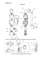
Parts List
23
OM/SM-TDH-CE
Parts List
CRANK TILT MODELS
PULL TILT MODELS
24
OM/SM-TDH-CE
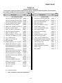
Parts List
(Keyed to Drawings on Pages 23 and 24)
To order parts, contact your Groen Certified Service Agency. Supply the model designation, part description,
part number, quantity, and, where applicable, voltage and phase.
Key
P/N
H
C
Key
Base Weldment (TDH-40)
113082
x
x
22
Base Weldment (TDH-20)
113083
x
x
23
2
Cladding, top, pedestal
113052
x
x
3
Cladding, side, pedestal (TDH-40)
113051
x
Cladding, side, pedestal (TDH-20)
1
Description
Description
P/N
H
C
Set collar
065528
x
Grommet
003492
x
x
24
Flue Stack Assembly
090686
x
x
x
25
Faucet Bracket
009054
x
x
113079
x
x
26
Tilt switch & bracket assembly
113074
Cladding, panel, pedestal (TDH-40) 113053
x
x
27
Pull Handle Assembly
012965
x
Cladding, panel, pedestal (TDH-20) 113080
x
x
28
Safety Valve Assembly (Steam)
005801
x
x
5
Pillow block, 1-1/2" bore
002989
x
x
Pressure Gauge
084208
x
x
6
Shim
122031
x
x
Safety Valve (Steam)
097005
x
x
7
Pedestal, machined (TDH-40)
113050
x
Waterfill Assembly
096923
x
x
Pedestal, machined (TDH-20)
113095
x
Check Valve
096915
x
x
8
Bearing with snap ring
002790
x
Ball Valve
096916
x
x
4
x
9
Worm shaft
113057
x
29
Gasket, Bottom Cover
007937
x
x
10
Worm gear 3/4" bore
012026
x
30
Thermostat Adapter
107172
x
x
11
Spacer Washer
084956
x
31
Screw, Rd Hd #6-32 x 3/8"
009697
x
x
12
Hand wheel
012061
x
32
--
13
Roll pin, 1/4" x 1"
012614
x
33
Bullseye Sight Glass
108554
x
x
14
Gear bushing
113055
x
34
Thermostat Knob
122054
x
x
15
Set screw, socket 3/8-16 x 1"
005593
x
35
Thermostat
012313
x
x
16
Gear sector, 12 DP
009829
x
36
Water Level Probe
015589
x
x
17
Key, 1/4" sq x 1-1/4" round ends
009262
x
37
Bottom Cover
003141
x
x
18
Spacer washer 1/4"
122117
x
38
Nut, Hex 1/4" x 20
012940
x
x
19
Pedestal, weldment (TDH-40)
128835
x
39
Pressure Switch
096963
x
x
Pedestal, weldment (TDH-20)
128834
x
40
Reducing Bushing, 1/2" x 1/4 NPT
008739
x
x
Tilt switch & bracket assembly
127635
x
41
Elbow Assembly
101543
x
x
Tilt Switch
002982
x
x
Washer, Lock, 3/8" MS [4]
005702
x
x
Nut, Hex #4-30 [2]
003121
x
x
Washer, Lock, 3/8" SS [4]
005618
x
x
Screw, Rd Hd #4-40 x 3/4" [2]
003122
x
x
Screw, Hex 3/8-16 x 1" SS [4]
005612
x
x
Washer, #4-40 [2]
013418
x
x
Screw Hex 1/2-13 x 1" SS [4]
005622
x
x
Bracket, Tilt Switch
113062
x
Washer, Lock, 1/2" [4]
005735
x
x
Bracket, Tilt Switch
127636
x
Nut, Hex, 1/2-13 [4]
005705
x
x
Stop assembly
065527
x
20
21
H = Pull Tilt Model
C = Crank Tilt Models
“–“ = Item not shown in illustrations
“[n]” = Quantity required
25
OM/SM-TDH-CE
Parts List
Gas Valve and Piping Assembly, TDH-20 and TDH-40 Natural and Propane Gas CE Models
Electrical Panel Assembly, TDH-40 and TDH-20 CE Models
26
OM/SM-TDH-CE
Parts List
(Keyed to Drawing on Page 26)
To order parts, contact your Groen Certified Service Agency. Supply the model designation, part description,
part number, quantity, and, where applicable, voltage and phase.
Key
Description
P/N
TDH-
Key
20 40
Description
Gas Combustion Parts
P/N
TDH20 40
Electrical Parts
G25 Gas Conversion Kit (from G20)
128884
G25 Gas Conversion Kit (from G20)
128885
x
1
Pilot Ignition Controller 220V/240V
113060
x
x
x
2
Screw hex washer #8-32x3/8" [5]
069789
x
x
Gas Valve & Piping Assy (Complete) 113065
x
x
3
Water Level Sensor Relay
117737
x
x
1
90º Street Elbow 1/2" NPT (black)
004185
x
x
4
Base, Relay Socket
117738
x
x
2
Union Elbow 1/2" NPT (black)
005495
x
x
5
Screw, rd head 6-32 x1" lg [2]
012631
x
x
3
Nipple Close 1/2"BSPTx1/2"NPT [2]
116394
x
x
6
Terminal Block (3 pole)
003119
x
x
4
90º Elbow 1/2" NPT (black)
008747
x
x
7
Screw, rnd hd #8-32x5/8" lg [2]
007526
x
x
5
Nipple, 1/2" NPT x 8" long (black)
005557
x
x
8
Label, Supply Voltage
114316
x
x
6
Gas Valve (Natural & Propane)
114505
x
x
9
Panel, electrical mounting
117726
x
x
7
Nipple, 1/2" NPT x 2" long
005551
x
x
10
Fuse Holder
077854
x
x
8
Bushing, Reducing, 1/2" x 3/8" NPT
012355
x
x
11
Screw, rd hd #6-32 x 1/4" lg
018384
x
x
9
Connector, 3/8" MNPT x 1/4" Tube
054498
x
x
12
Fuse, Three Amp (250V)
079965
x
x
10 Tee, 1/2" NPT (black)
008772
x
x
13
Label, “3 Amp (Fast Blow Only)”
102251
x
x
12 Nipple, 1/2" 1/2" Close BT
008877
x
x
14
Electrical Panel Assembly complete 113069
x
x
13 Gas Test Nipple
117051
x
x
--
Equipotential Terminal Assembly
122021
x
x
14 Bushing, Reducing 1/2" x 1/8" NPT
088290
x
x
--
Light, Indicator, Red
116381
x
x
122087
x
x
--
Light, Indicator Amber
116382
x
x
x
--
Switch, Pushbutton, Momentary
122003
x
x
--
Switch, Toggle
122004
x
x
--
Wire Harness
113081
x
x
15 Adapter 1/8" f. BSPx1/8" m. NPTF
--
Burner & Manifold Assy (G20 Gas)
113066A
--
Burner & Manifold Assy (G20 Gas)
113068A x
--
Manifold Assembly
040822
x
091845
x
--
Burner Jets (1.09 mm) for G20 [12]
--
Manifold Assy w/burner jets G20
--
Burner Jets (0.94 mm) for G20 [8]
127562
x
--
Pilot Burner & Orifice Assy G20/G25 117700
x
x
--
Pilot Tubing
113088
x
x
--
Sensing Probe (pilot)
003328
x
x
--
Connector 3/8"MNPTx1/4" tube
054498
x
x
--
Adapter, gas 1/2" BPST x 1/2"NPT
116390
x
x
--
Flue Stack Assembly
090686
--
Flue Stack Assembly
093605
x
--
Gas Inlet Valve
098458
x
097054C x
x
x
“[n]” = Quantity required
“–“ = Item not shown or called out in illustrations
27
OM/SM-TDH-CE
28
OM/SM-TDH-CE
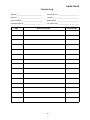
Service Log
Model m _______________________________
Purchased From _________________________
Serial m _______________________________
Location ________________________________
Date Purchased __________________________
Date Installed ___________________________
Purchase Order m ______________________
For Service Call __________________________
Date
Service Performed
29
Performed By
OM/SM-TDH-CE
Limited Warranty To Commercial Purchasers*
(for Areas Outside of the U.S. and Canada)
Groen Foodservice Equipment ("Groen Equipment") has been skillfully manufactured, carefully inspected and
packaged to meet rigid standards of excellence. Groen warrants its Equipment to be free from defects in material
and workmanship for (12) twelve months from date of installation or (18) eighteen months from date of shipment
with the following conditions and subject to the following limitations.
I.
This parts warranty is limited to Groen Equipment sold to the original commercial purchaser. users (but not
original equipment manufacturers), at its original place of installation, in areas outside the U.S. and
Canada.
II. Damage during shipment is to be reported to the carrier, is not covered under this warranty, and is the sole
responsibility of the purchaser/user.
III. Groen, or an authorized service representative, will repair or replace parts, at Groen's sole election, for any
Groen Equipment, including but not limited to, drawoff valves, safety valves, gas and electric components,
found to be defective during the warranty period.
IV. This warranty does not cover boiler maintenance, calibration, or periodic adjustments as specified in
operating instructions or manuals, and consumable parts such as scraper blades, gaskets, packing, etc.,
or labor costs incurred for removal of adjacent equipment or objects to gain access to Groen Equipment.
This warranty does not cover defects caused by improper installation, abuse, careless operation, or
improper maintenance of equipment. This warranty does not cover damage caused by poor water quality
or improper boiler maintenance.
V. THIS WARRANTY IS EXCLUSIVE AND IS IN LIEU OF ALL OTHER WARRANTIES, EXPRESSED OR
IMPLIED, INCLUDING ANY IMPLIED WARRANTY OF MERCHANTABILITY OR FITNESS FOR A
PARTICULAR PURPOSE, EACH OF WHICH IS HEREBY EXPRESSLY DISCLAIMED. THE REMEDIES
DESCRIBED ABOVE ARE EXCLUSIVE AND IN NO EVENT SHALL GROEN BE LIABLE FOR SPECIAL,
CONSEQUENTIAL OR INCIDENTAL DAMAGES FOR THE BREACH OR DELAY IN PERFORMANCE OF
THIS WARRANTY.
VI. Groen Equipment is for commercial use only. If sold as a component of another (O.E.M.) manufacturer's
equipment or if used as a consumer product, such Equipment is sold AS IS and without any warranty.
* (Covers All Food Service Equipment Ordered After October 1,1995)
30
1055 Mendell Davis Drive
Jackson, Mississippi 39272
Telephone 601 373-3903
FAX 601 373-9587
OM/SM-TDH-CE
INTERNATIONAL
Part Number 128418
Revised October1999