1
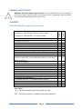
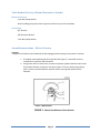
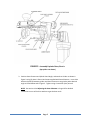
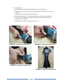
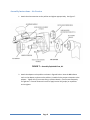
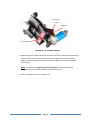
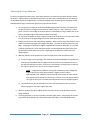
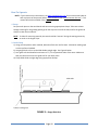
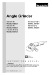
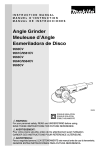
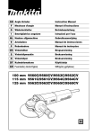
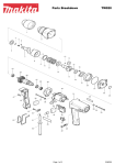
SEAM PHANTOM™
INSTRUCTION MANUAL
Model No. 0010-1
Please read this instruction manual thoroughly to ensure safety and correct use of tool.
Keep this manual in a place where operators can access it easily, anytime when necessary.
PATENT Number: US 8,162,726
MADE IN USA
www.nsisolutions.com
Manual Rev J3
INTRODUCTION
Thank you for purchasing the NSI Solutions SEAM PHANTOM®. Please read this instruction manual
thoroughly for assembly instructions, safe operation, tool handling, tool capabilities information, and all
other precautions before using the tool. Keep this manual in a place where operators can access it
easily.
In order to be used, the SEAM PHANTOM® is assembled to an angle grinder or polisher. Observe all of
the Operational and Safety instructions contained in the Instruction Manual supplied with the angle
grinder or polisher.
TABLE OF CONTENTS
INTRODUCTION ............................................................................................................................................. 2
GENERAL SAFETY RULES................................................................................................................................ 3
ASSEMBLY ..................................................................................................................................................... 3
SEAM PHANTOM Packages and Accessories ............................................................................................ 3
Tools Needed For Assy Of Seam Phantom® to Grinder ............................................................................. 4
Assembly Instructions – Electric Version .................................................................................................. 4
Assembly Instructions – Air Version ......................................................................................................... 8
Adjusting the Seam Phantom ................................................................................................................. 10
USE INSTRUCTIONS ..................................................................................................................................... 11
Before Using the Seam Phantom - Preparations .................................................................................... 11
How To Operate ...................................................................................................................................... 12
CLEANING AND MAINTENANCE .................................................................................................................. 14
CONTACT NSI SOLUTIONS ........................................................................................................................... 16
Page 2
GENERAL SAFETY RULES
ASSEMBLY
Package SP-E: Seam Phantom® Electric Grinder Package
®
Package SP-A: Seam Phantom Air Polisher Package
Pkg SP-A
SEAM PHANTOM Packages and Accessories
Pkg SP-E
!
WARNING: Read and understand all instructions. Failure to follow all instructions listed below,
may result in electric shock, fire and/or serious personal injury. Additionally, observe all safety
instructions provided with the electric and air tools.
(1)
(1)
(1)
(1)
(1)
●
Opt
Opt
●
●
●
●
●
Opt
●
●
●
Seam Phantom
Adapter for Air Tool
Arbor Extension
Arbor Spacer
Splash Guard Angle
Screws Required for Assembly
(4) Washers (to allow for angling of the grinding head)
(1) Spray Skirt
(1) Makita 9565CV or 9564CV angle grinder
(1) Center Water Feed Air Polisher (Alpha Air-658, Barranca BD-2321,
Hercules, or equivalent. Units shipped after approx 1-1-2013 also fit
WEHA model Q-V9.)
(1) 48” Glide Guide Rail
72” Glide Guide Rail
96” Glide Guide Rail
(1) Tool Box for Seam Phantom and Attachments
(1) GFCI
(1) Phantom SL3-ADAPT – 5/8-11 Adapter (M14 Adapter is available)
(1) Phantom SL3-60 Turbo Pad
(1) Phantom SL3-150 Turbo Pad
(1) Phantom SL3-300 Turbo Pad
(1) Phantom SL3-Cup 2 – 2” Cup Wheel for back grinding
(2) C-Clamps for clamping Glide Guide
(2) Gauge Blocks
(1) Assy and Usage Instruction Manual
KEY
●
NOTE
These items supplied with the package as noted.
Opt
These items optional – available for purchase separately.
Page 3
●
●
Opt
●
Opt
Opt
●
●
●
●
●
●
●
●
●
●
●
Opt
Opt
Opt
●
●
●
●
●
●
●
●
Tools Needed For Assy Of Seam Phantom® to Grinder
Electrical Version
3 mm Allen (Hex) Wrench
Alcohol (rubbing) to prepare electric grinder surface for spray skirt installation
Air Version
3/4” Wrench
1/8 Allen (Hex) Wrench
3 mm Allen (Hex) Wrench
Assembly Instructions – Electric Version
CAUTION:
• Always be sure that the tool is switched off and unplugged before carrying out any work on the tool.
1. If installed, remove wheel guard from grinder (See Figure 1). Guard will not be reinstalled for use with the Seam Phantom.
2. Using a 3mm Allen or Hex wrench, remove the quantity (4) 4mm diameter Hex screws
from head of Grinder at locations as shown in Figure 2. Do not remove the grinding
head. Screws can be discarded or saved for future use of grinder without Seam
Phantom.
Item 1 – Wheel Guard
FIGURE 1 - Wheel Guard Removal from Grinder
Page 4
FIGURE 2 – Assembly Exploded View, Electric
(Spray Skirt not shown)
3. Position Seam Phantom and Splash Guard Angle, and attach to Grinder as shown in
Figure 2 using (4) 4mm X 22mm Hex Screws supplied with Seam Phantom. Insert shim
washers (optional) between grinder and Seam Phantom to set grinder pad at desired
angle as noted below and in Figure 2. Tighten using a 3mm Allen (Hex) wrench.
NOTE: See section titled Adjusting the Seam Phantom on Page 10 for detailed
instructions on use of the shim washers to get the best result.
Page 5
4. Install Spray Skirt
a) Clean grinder with denatured (rubbing) alcohol prior to installing skirt
b) Mark the center of the skirt along the top edge to help center the spray skirt on the
grinder
c) Install approx. 1/4 inch below the switch as shown
d) Tape is extremely sticky - care should be taken once the tape backing is removed
e) Skirt must be installed without gaps or wrinkles in the tape to minimize water
penetration to the grinder
f) Fold back skirt and blow out grinder after each use
FIGURE 3 – Spray Skirt Installation, #1
FIGURE 4 – Spray Skirt Installation, #2
FIGURE 5 – Spray Skirt Installation, #3
FIGURE 6 – Spray Skirt Installation, #4
Page 6
5. If desired, fasten water supply hose to cord of Grinder using electrical tape or other
suitable method.
6. Install arbor spacer (see Figure 2) and SL3 Adapter. Unit is now ready for use.
CAUTION: Ensure electrical circuit supplying grinder is protected by a ground fault circuit
interrupter (GFCI).
Page 7
Assembly Instructions – Air Version
1. Attach the arbor extension to the polisher and tighten appropriately. See Figure 7.
FIGURE 7 – Assembly Exploded View, Air
2. Attach the adapter to the polisher as shown in Figure 8 below. Note the UP indicator
mark on the adapter, and ensure the polisher is installed in the proper orientation to the
adapter. Tighten the (5) set screws using a 1/8 Hex Wrench. Check screws frequently
for tightness. If screws loosen with use then apply Loctite 222 (purple) or equivalent
and re-tighten.
Page 8
Set Screws
(5 ea)
Adapter
‘UP” Indicator
FIGURE 8 – Air Polisher Adapter
3. Attach the polisher, adapter and arbor extension to the rest of the Seam Phantom using
(4) 4mm X 22mm Hex Screws (supplied) as shown in Figure 7. Insert shim washers
(optional) between adapter and Seam Phantom (see Figure 7) to set polishing pad at
desired angle.
NOTE: See section titled Adjusting the Seam Phantom on Page 10 for detailed
instructions on use of the shim washers to get the best result.
4. Attach SL3 adapter and unit is ready for use.
Page 9
Adjusting the Seam Phantom
To ensure the tightest possible seams, each Seam Phantom is checked for squareness before it leaves
the factory. Slight variations in grinders and polishers can affect the finished product so shim washers
are provided to make final adjustments. A newly assembled Seam Phantom/grinder should be tested
and adjusted utilizing a sample seam ground on scrap stone as follows:
1. On a scrap piece of stone set up the Glide Guide and grind the first half of a finished seam
per the instructions on page 12 and 13 of the manual, steps 1, 2 and 4. Skip step 3, “back
grind”. Dress the entire edge of the stone with the Turbo Pads to 150 grit. Make sure all the
chips in the upper edge of the seam have been eliminated.
2. On a second scrap piece of stone create the mating half of the seam in the same way. Make
sure all the chips in the upper edge of the seam have been eliminated.
3. Place the two halves of the finished seam together. Make sure the top of the sample is even
and flat and observe the gap at the edge of the seam. The seam should be tight on the top
edge. A slight gap on the bottom edge is acceptable and sometime desirable. It is a matter
of personal preference. Some fabricators prefer to make perpendicular tight seams from
top to bottom. Other fabricators prefer a slight gap on the bottom to ensure the top is
always tightest.
4. Add shim washers to the attachment screws as required to create the desired seam.
a) To correct a gap on the top edge, shim washers can be placed between the grinder and
seam phantom (between the air adapter and seam phantom on air powered units) on
the top two attachment screws. Utilize one or two washers on each screw as required.
See Figure 2 (electric) or 7 (air) for correct washer location.
NOTE: A single washer added to the top two attachment screws changes the
angle of the Turbo Pad by approximately ¼ degree and will result in
approximately .005” additional stone removed at the bottom of a 3cm sample
(the approximate thickness of a human hair). This will correct an approximately
.010” gap at the top of a finished seam when both halves are brought together.
b)
Shim washers may also be utilized on the lower two attachment screws to close an
overly large gap on the lower edge of the seam.
5. After the washers have been added repeat the process to ensure the desired seams are
being produced.
6. The seam phantom is now set to produce consistent tight seams. Occasionally this process
may need to be repeated as the plastic base plate that slides on the Glide Guide wears.
Page 10
USE INSTRUCTIONS
Before Using the Seam Phantom - Preparations
Before using the assembled Seam Phantom, be sure to complete the following preparations.
!
!
!
1. Supply the specified voltage (electric version)
Supply the voltage specified on the nameplate of the machine. Otherwise damage could result to the
machine, or increase the risk of personal injury.
2. Install a Ground Fault Circuit Interrupter (GFCI) (electric version)
WARNING: To prevent electrical shocks, be sure that the power circuit being used is protected by a
GFCI device, or be sure to install a ground fault circuit interrupter (GFCI) between the main power
supply and the cord of the machine.
3. Ensure Spray Skirt and Shield are installed (electric version)
WARNING: Do not let water into the motor of the electric grinder. Water inside the machine will
weaken the electrical insulation of the motor and may result in electric shock. Ensure upper spray
shield and lower spray skirt are installed at all times during use .
!
4. Organize the Work Area for Safe Operation
Before beginning operations, make sure that the work area conditions are well organized for safe
operation of the Seam Phantom.
!
5. Use Proper Safety Gear
To prevent damage to eyes from flying debris, wear protective glasses or face shield.
Be sure to wear waterproof safety boots.
Page 11
How To Operate
NOTE: If you have access to the Internet, see www.seamphantom.com for an instructional video as
well as pictures of the process (Menu: Seam Phantom, then “Seam Phantom Process”). This
manual will also be available in the Support section.
1. Setup
Set your work piece on the work bench and secure it using appropriate clamps. Take care to leave
enough overhang for the grinding pad to get all the way to the end of the slab, and for the guide rail
clamps to clear the work bench.
NOTE: To allow for removing material, the seam should be “overcut” during the sawing process by
as much as the largest chips.
2. Guide Setup
a) Using your template or other method, determine final trim line for Seam. Mark with masking tape
or other preferred method.
b) Use gauge blocks to line up the Glide Guide straight edge. See Figure 9 below.
c) Your guide rail should extend a minimum of 3” (7.5 cm) past both sides of the stone. Make sure
that you select the correct size guide rail for your work piece.
d) Clamp Glide Guide straight edge using appropriate Clamps
FIGURE 9 – Gauge Block Use
Page 12
3. Back Grind or “Undercut”
The back grinding is done using the Phantom SL3™ 2" cup wheel. Ensure adequate water flow is
provided by adjusting the valve. Use the 2" cup wheel to grind slightly more material than you'll be
dressing off with the turbo pads. Be sure to stop the back grind short of the front "profiled" edge to
avoid a large gap in the front edge. This back grind will allow the turbo pads to dress the seam more
efficiently and also provide a rough surface for the seaming adhesive to stick to.
!
WARNING: The Phantom SL3™ Cup Wheel is made to be used with water. With the electric model,
adjust water flow to ensure the water is hitting the “backstop” of the SL3 2” cup wheel and splashes
onto the grinding area. With the air model, the water is fed through the center water feed of the
polisher. DO NOT OVERHEAT the Cup Wheel by operating it dry. Max speed for the 2” Cup Wheel is
10,000 RPM.
4. Dressing the Seam (Suggested Process)
a) Start with either the SL3 60 or 150 Grit Turbo Pad.
NOTE: The decision will depend on the size of chips in the edge, and how much material is to be
removed.
b) Use adjustment knob to back off tool so that grinding pad is not touching the stone.
c) Turn on the power and water. Adjust the water flow by rotating the valve part way.
NOTE: The electric version has the water valve mounted on the Seam Phantom itself. Keep the
water volume turned down low to minimize the amount of water that sprays onto the
electric grinder.
!
WARNING: Max speed for the The Phantom SL3™ Turbo Pads is 4,000 RPM. Do not run at a higher
RPM or premature wear or damage can result.
d) Turn adjustment knob clockwise until grinding pad just touches stone and begin grinding the
seam.
e) Turn the adjustment knob to gradually cut deeper. Adjust in gradually until the cut is almost to
the final marks (stopping short to allow the 300 grit to finish).
NOTE: For best results, only apply pressure to the tool using aluminum handle above the flat
surface of the straight edge. Do not apply pressure via the grinder or by pushing on the
adjustment knob.
f) Repeat process using 300 Grit Pad. (This is personal preference and depends on the type of
material being dressed. You might find that your results from the 150 Grit Pad are sufficient.)
g) Continue until seam is at marked line and no edge chipping. Continuing until pad barely touches
stone will ensure a straight and chip free edge.
5. After Use
Clean and dry the electric grinder as noted in the Cleaning and Maintenance section.
Page 13
CLEANING AND MAINTENANCE
!
CAUTION:
Always be sure that the tool is switched off and unplugged before attempting to perform inspection
or maintenance.
The tool and its air vents have to be kept clean. Regularly clean the tool’s air vents or whenever the
vents start to become obstructed.
To maintain product SAFETY and RELIABILITY, repairs of the electric or air tools should be done by an
Authorized or Factory Service Center.
1. Blow Out Electric Grinder
Fold back spray skirt and blow out grinder vents after each use using a dry air supply to remove any
dust or moisture. This will extend the life of the electric motor.
2. Cleaning Guide Rods and Bushings
After heavy use, the in and out adjustment of the Seam Phantom may become “stiff”. Performing
the following steps should correct this. See Figure 10.
a) Disconnect the water feed hose (electric version only) at the valve end with the quick disconnect
tube fitting, by pushing the ring towards the hose fitting.
b) Extend the adjustment by turning the adjustment screw until the two halves of the Seam Phantom
can be separated. Do not lose the square adjustment nut.
c) Use a paper towel or other soft material and push through the bushing holes, sliding back and
forth until all grit is removed.
d) Using a soft towel or material, wipe the stainless shaft guide rods clean.
e) Clean screw threads on the adjustment screw.
f) Reassemble the two halves and re-connect the water hose by pushing it in until it snaps in place.
Page 14
FIGURE 10 – Cleaning (Electric version shown)
3. Air Tool
Perform regular oiling and other maintenance of the air polisher as recommended by the
manufacturer.
Page 15
CONTACT NSI SOLUTIONS
Whether it’s for replacement parts, technical or usage support, or just to brag about how tight
your seams are, feel free to contact us. For problems with the electric or air polisher, please
contact the manufacturer direct for warranty replacement or work.
Here’s how to reach us:
Main Phone:
425-297-3162
Fax:
425-513-2388
Web:
www.nsisolutions.com
Email address: [email protected]
Mail:
1205 8th DR
Mukilteo, WA 98275
Usage Tips:
For usage help and/or tips:
- www.nsisolutions.com and go to the Media or Support sections which includes
FAQs, or
- www.stonefabricatorsalliance.com and search for “Seam Phantom” or ask your
question in an appropriate forum.
Page 16