1
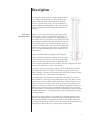
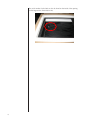
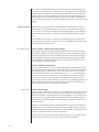
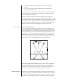
Owner’s Manual
Sage S90i
In-Wall Subwoofer
Table of Contents
Introduction.....................................................................................................4
About this manual...................................................................................................4
Please register your system.....................................................................................4
Description......................................................................................................5
Regenerative Transmission Line™............................................................................5
Unpacking the S90i..........................................................................................6
Remote Setup via Modem.......................................................................................8
Room Acoustics & Placement...........................................................................9
Start With the Room...............................................................................................9
Rigid Walls.......................................................................................................9
Speaker Placement................................................................................................10
Left & Right Speakers.....................................................................................10
Center Channel..............................................................................................10
Surround Speakers......................................................................................... 11
Subwoofer Placement........................................................................................... 11
Room Treatment...................................................................................................12
Professional Acoustic Design................................................................................12
References............................................................................................................13
Installing the S90i in a Wall...........................................................................14
Installing the S90i in the Ceiling....................................................................16
Tips and Ideas.......................................................................................................24
Black out the HVAC and snorkel....................................................................25
Limited access situations................................................................................26
Installing under the floor................................................................................26
Making the S90i Connections........................................................................28
Optimizing the System...................................................................................29
North American Warranty.............................................................................30
Standard Warranty................................................................................................30
Harsh Conditions Use...........................................................................................30
Obtaining Service..........................................................................................31
Specifications.................................................................................................32
S90i Dimensions............................................................................................33
Notes..............................................................................................................34
Introduction
Congratulations on purchasing your Wisdom Audio in-wall subwoofer. The
S90i’s Regenerative Transmission Line™ technology delivers tremendous bass
performance in terms of depth, dynamics, and distortion resulting in articulate bass that integrates seamlessly with high-resolution main speakers such as
Wisdom Audio’s Sage Series.
About this manual
This manual focuses on the S90i subwoofer itself. In order to fully understand
the system, we recommend you also review the manual for the SC-1 System
Controller, without which this subwoofer will not perform correctly.
While we expect your local Wisdom Audio dealer to take care of the setup and
calibration of the system, we still recommend that you at least briefly review this
and the other manuals (SC-1, SA-series amplifiers) to understand the system’s full
capabilities.
Please register your system
To register your warranty, please complete the form at the following address on
the internet:
http://www.wisdomaudio.com/registration/
Doing so will ensure that there will be no delays should you ever require warranty service. If accessing the internet is inconvenient, you can send a copy of
the sales receipt (showing your name, address and the products purchased) to
the address shown in the North American Warranty section of this manual.
Wisdom Audio does not and will not ever share its mailing list with other companies. Nor do we expect to contact you frequently, since you are buying a
product that should last a lifetime. However, we would like to be in a position to
contact you should a software update become available for the system controller (as an example).
Lastly, please keep your sales receipt in a safe and easily found place. If you do
not register your purchase with the company, it is your only proof of warranty.
4
Description
Your Sage S90i subwoofer uses a modern implementation
of an old idea for high quality, low distortion bass reproduction. While the roots of the Regenerative Transmission Line™ go back to the 1950’s, it is the combination of
modern computer modeling and the vastly more powerful
motors of contemporary driver design that make the RTL™
so special.
Regenerative
Transmission Line™
There is a class of bass enclosures that has been around
since the 1950’s, which can be described generically as
“low frequency tapped waveguides” or “tapped pipes.” It
was an idea that was a bit ahead of its time then, since fully
optimizing its use required both powerful drivers and computer modeling. But if you are into such things, check out
US Patent 2,765,864 (filed in 1955), and an AES paper published in 1959, “Analysis of a Low Frequency Loudspeaker
System.” We have published both on our website for your
convenience, at
http://www.wisdomaudio.com/support_documents.php
We have utilized sophisticated modeling software in order
to fully optimize our enclosures, and have developed drivers that are specifically optimized for this application. We
call our unique implementation of this relatively old idea a “Regenerative Transmission Line™” subwoofer, or “RTL” sub for short.
All dynamic drivers develop energy on both sides of the diaphragm, with the
rear energy being 180° out of phase with the front energy. If you allow the
driver to operate in free space (no enclosure), the front and rear energies largely
cancel each other out — especially at low frequencies.
In our Regenerative Transmission Line™ subwoofer, the energy from the back
side of the driver is sent along a long, folded path in such a way that its lowest
frequencies arrive back at the front side of the driver in phase, effectively summing to an increase of 6 dB in output. Thus, the energy from both sides of the
woofer cone is used in a productive way, resulting in a substantial reduction in
distortion and an effective surface area double compared to what you would
otherwise expect. As an example, the effective radiating surface area in the S90i
is roughly equivalent to a 13” diameter round woofer, yet the enclosure fits in a
5.5” deep stud bay.
The results are quite stunning. Low frequencies are strikingly dynamic and responsive, and integrate quite seamlessly with the fast and detailed Sage Series
planar magnetic hybrids. As an example, the S90i is easily hidden in the wall,
yet is flat to 20 Hz and can output in excess of 120 dB at 20 Hz (measured at its
output port to minimize the room’s effects on the measurement).
5
Unpacking the S90i
The Wisdom Audio Sage S90i subwoofer is a substantial piece of equipment.
Please exercise caution when unpacking your S90i to ensure that you do not
strain yourself from its (perhaps unexpected) weight.
Caution!
Do not attempt to lift your S90i by yourself. Unpacking this
subwoofer is easy for two people, but it is unwise for a single person
to attempt doing so.
Do not attempt to lift your S90i while bending or twisting from the
waist. Use your legs for lifting, not your back.
Always stand as straight as possible and keep the S90i close to your
body to reduce strain on your back.
The S90i is fully assembled on delivery:
The front surface has a smooth, resin-coated paper finish that can be taped and
spackled, and then painted to match the adjacent drywall (gypsum board).
6
The end of the speaker that contains the grille assembly also includes the “pigtail” for connecting the speaker to the system, as well as some “feet” to support
the S90i slightly above the sole plate, to allow room for the wiring and the baseboard of the finished wall. (Rooms with unusually tall baseboards may require
the S90i to be mounted somewhat higher still.)
The grille itself is friction-fit into its frame using rubber channels on its edges.
Removing the grille exposes the black service panel, which only needs to be
removed in the unlikely case that one or more drivers needed to be replaced
after installation in the wall.
The Regenerative Transmission Line™ opening occupies a little less than half the
space covered by the grille.
7
The serial number for the S90i can also be found on the inside of the opening
for the Regenerative Transmission Line.
8
Room Acoustics & Placement
Wisdom Audio believes in equalization. Assume for a moment that you had a
“perfect” loudspeaker: as soon as you place it in your room, its perfection is
gone. In fact, even good rooms often introduce deviations of 20 dB to the response of the system. This is particularly true in the bottom two octaves, where
a subwoofer operates.
It seems strange to us to worry about tenths-of-a-decibel differences between
one component and another when there are 10-20 dB problems right there in
the room with you.
At the same time, room equalization is not a panacea. It does not solve all problems. In fact, and somewhat paradoxically, EQ works best when it has the least
to do. It is best used as the “finishing touch” on an otherwise good system. Unfortunately, most people do not understand that the most important component
in their system is their listening room.
This manual does not have the space for a full description of everything that
goes into creating excellent room acoustics; doing so would require a textbook
of several hundred pages. Instead, we will give you some ideas, and some references to pursue should you want to learn more.
Start With the Room
There are many myths floating around pertaining to what a “good room” should
be like. One of the most common is that it should have non-parallel walls. Without going into the details, we recommend staying with rectangular rooms whose
dimensions do not share common divisors.
Thus a room with dimensions of 8’ by 16’ by 20’ would be quite poor (since the
dimensions are all divisible by a length of 4’, and 16 is also a multiple of 8). By
contrast, a room whose dimensions are 9’ by 16’ by 29’ would be much better,
since none of the dimensions are mathematically related to one another.
There are infinite variations on this idea. If you have the flexibility to choose (or
modify) your room dimensions to avoid such problems, do so. Either way, our
room correction will be a big help.
Rigid Walls
Another myth that should be dispelled is the notion that the walls (and ceiling
and floor) of the room should be extremely rigid in order to reproduce good
bass. Rigid, inflexible walls reflect energy extremely well; thus you will keep
more of the bass energy in the room. This much is true. However, those rigid
walls will only increase the amplitude of the standing waves that your room
naturally supports. In simple terms, you will have more bass, but it will also be
more irregular, with larger peaks and valleys in the response.
Walls that flex a bit (but do not rattle) are much better. Coincidentally, traditional American residential construction standards (sheet rock on wooden studs) are
not a bad place to start. You can do better still with professional help, but studs
and sheet rock are better than poured concrete. (If your listening room is in the
basement, a false wall can easily be built in front of the concrete. You probably
need something like this for insulation and aesthetics anyway.)
9
The ultimate in dedicated listening room construction involves the design and
construction of floating walls, ceiling and floor. This approach yields the added
benefit (when done properly) of providing outstanding acoustic isolation from
adjacent spaces as well as superb bass reproduction. This approach goes well
beyond the scope of an owner’s manual; if you are interested, you should contact a professional acoustician who has specialized in this sort of domestic room
design.
Speaker Placement
Within the room itself, placement of the speakers and the listener will have a
profound effect on the performance of the system, particularly below 300 Hz
or so. There is no “perfect” position that will solve all problems, but finding the
best compromise will make it easier to solve the remaining problems with the
SC-1.
Your Wisdom Audio dealer can help you with optimizing your speaker placement, which is never quite as simple as it seems it should be. The characteristics
you should listen for are several:
Left & Right Speakers
Goal #1: Stable, 3-dimensional stereo imaging
This usually requires reasonable symmetry within the room, and a bit of space
between the speakers and adjacent side walls (to minimize the adverse effects
of early first reflections). Mono (correlated) pink noise can help here, though it
does not replace listening to music. With pink noise playing in both speakers,
you should hear a tightly-defined little “ball” of pink noise floating in space exactly halfway between the speakers.
Goal #2: Smooth, consistent bass
Oft-cited rules of thumb for smoother bass reproduction include both “placing
the speakers at different distances from the side walls vs. the wall behind them,”
and “placing them at ‘odd fractions’ of the room’s dimensions” (e.g., fractions
in which the denominator is an odd number, like 1⁄ 3, 2⁄5, 2⁄ 7, etc.). But nothing
replaces your experience in your room, combined with your dealer’s experience in a variety of rooms. Playing pink noise through the woofer sections of
your Wisdom Audio speakers (with the microphone at the listening position, and
prior to doing any equalization) and watching the results on a Real Time Analyzer (RTA) will let you see the results of your labors.
Center Channel
Center channel height
Once you have a solid stereo image up front (when listening only to the Left and
the Right speakers), you need a center channel speaker for multichannel reproduction. It should be centered between the Left and Right, and centered on the
screen’s location, preferably at the same height as the Left and Right speakers.
This presents an obvious problem: you cannot place a speaker in front of your
television screen.
Ideally, a center channel speaker would be behind an acoustically transparent
front projection screen and would match the Left and Right speakers. Doing so
would ensure the best possible consistency of tonal balance, image height, and
dynamic capabilities for the critical center channel.
Another way to achieve similar results without relying on an acoustically transparent front projection screen is to use a total of four front speakers:
10
• two widely-spaced line source speakers handle the Left and Right
channels;
• two line source speakers closely flanking the screen both play the
(mono) center channel signal.
This approach creates a stunningly convincing “phantom” center image that appears to emerge directly from the center of the picture, while allowing you to
use any display device you choose.
Failing an acoustically transparent screen or a phantom center channel approach, the important thing is to match the tonal and dynamic capabilities of the
Left and Right speakers while minimizing the change in image height as a sound
is panned across the front stage. Wisdom Audio has designed horizontally-oriented planar magnetic hybrid speakers that will match your Sage loudspeakers
superbly; place them as close to the edge of the screen as is practical.
Surround Speakers
Surround channel geometry
In a 5.x channel system, the surround should be placed either directly to the
sides of or slightly behind the listening area (90°–110° from the center channel,
as seen from above). In a 7.x system, the surround speakers should be closer to
90° from the center speaker, and the surround back speakers should be at approximately 135°–150° from the center speaker. This conforms to industry standards, and ensures that you hear what was intended from a spatial placement
point of view. (Too often, the surround speakers are all behind the listeners, creating a big “hole” in the soundfield between the front and the back.)
L
Sub 1
R
C
0°
22°
30°
Sub 2
90°
Ls
Rs
110°
135°
Lb
150°
Rb
a 7.2 channel system layout
One possible exception to these guidelines: if you have a THX®-certified processor and are using the THX Advanced Speaker Array™ circuitry, you should
follow the guidelines in your owner’s manual for the processor. Using this
technology, it can actually be more effective to have the rear speakers in a 7.x
system directly behind you and immediately adjacent to each other.
Subwoofer Placement
Subwoofers offer somewhat greater flexibility in placement, since the frequencies they reproduce are not readily localizable by the human ear. This is due to
the fact that the wavelengths they reproduce are more than ten feet (3 meters)
long, but our ears are located only about 6-7 inches (17 cm) apart. Thus these
11
extremely long waves do not contribute meaningfully to the imaging that the
main speakers create.
However, this fact does not mean that the placement of the subwoofers has no
effect on the sound quality in the room. Far from it. The subwoofers are the
most likely to suffer from the response irregularities introduced by the room
itself, operating as they do below approximately 80 Hz in most systems.
Recent research into the behavior of rooms as a function of speaker placement
has concluded that — if you have the freedom to do so — there are significant
advantages to placing several smaller subwoofers around the room, rather than
relying on a single large woofer. Moreover, the optimum placement is usually
centered on each of the four walls, or deep in the corners of the room. If you
have the luxury of doing so, this simple placement strategy can reduce the size
of the room’s response irregularities from 20 decibels down to perhaps as little
as 6-8 decibels—a tremendous improvement.
Reducing the room’s inherent problems to this degree provides a huge advantage. It allows the SC-1 System Controller to put its considerable abilities to work
on perfecting your system’s response, rather than on trying to perform major
corrective surgery.
Room Treatment
Rectangular rooms have six reflecting surfaces (four walls, ceiling and floor)
that reflect sound to the listener, after various delays introduced by the indirect
routes the sound take on their way to the listener. These first reflections are particularly damaging to sound quality. Looking at the simplest case of stereo reproduction, you have a minimum of twelve first reflection points in your room that
deserve some attention.
Unfortunately, it is often difficult to do much about the ceiling and floor reflections, even though they are arguably the most destructive. (The minimization of
these reflections is one of the strongest arguments for the tall, line source loudspeakers that Wisdom Audio builds.) This leaves you with eight “first reflections”
that you should consider minimizing somehow. These points are easily found by
having an assistant slide a small mirror along the four walls of the room, while
you sit at the listening position. Any place on the wall where you can see a reflection of any speaker is a first reflection point. Concentrate on the first reflections for the Left and Right speakers first.
If you can, arrange to apply either absorption or diffusion at these eight points
(don’t forget the wall behind you). Absorption can be as simple as heavy, insulated drapes; diffusion can be provided by a well-stocked bookcase with books
of varied sizes. Alternatively, you can buy purpose-designed room treatments
(some sources listed under References, below).
The important things to remember are these: a good room should have a balance of absorption and diffusion; and if you are going to treat only a few areas
of the room, the first reflection points are the most important ones to treat.
Professional Acoustic Design
Does this all sound too complicated? For good reason: it is complicated.
The difference between the average listening room and one that is professionally
designed and implemented is huge. A great listening room will disappear to an
astonishing degree, letting the experiences captured in your recordings speak to
12
you directly. A well-designed room is also quieter and more comfortable. It can
easily become a favorite retreat for peace and rejuvenation.
If you decide to investigate the possibility of improving your room with the help
of a professional, it is important to find someone who focuses on residential
spaces. Most acousticians are trained to deal with large spaces — airports, auditoriums, lobbies in commercial buildings, etc. The problems seen in “small”
rooms (residential spaces) are quite different, and outside the experience of most
acousticians. Find someone who specializes in and has a great deal of experience designing home studios, home theaters, and the like. Your Wisdom Audio
dealer may be such a person; failing that, he/she can help you find such a professional.
References
Books on Acoustics:
The Master Handbook of Acoustics, F. Alton Everest, TAB Books
Sound Reproduction: The Acoustics and Psychoacoustics of Loudspeakers and
Rooms by Dr. Floyd Toole, Focal Press
Suppliers of Acoustic Treatments:
Acoustic Innovations, http://www.acousticinnovations.com/
Acoustic Sciences Corporation, http://www.acousticsciences.com/
Echo Busters, http://www.echobusters.com
MSR Acoustics, http://www.msr-inc.com/home_theater/hometheater.html
RPG Diffusor Systems, http://www.rpginc.com/
13
Installing the S90i in a Wall
Your dealer has extensive knowledge of wall construction, and will customize
these installation instructions to suit the needs of your particular situation. But
these notes provide an overview of the process.
Note that the Regenerative Transmission Line opening that vents the low frequencies into the room may be placed either up near the ceiling, or down
near the floor. In most rooms, these are largely equivalent positions in terms
of acoustics. The difference will usually be aesthetic rather than performancebased.
As seen from above, a cross sectional view of the S90i as mounted in a typical
2 x 6 stud wall looks like this:
The front board of the S90i is made from 5⁄8” MDO plywood, which presents a
smooth, paintable finish surface similar to dry wall. It can be butted up against
the 5⁄8” dry wall, taped, and spackled, and painted like any other section of wall.
It will also readily accept skim-coating if the construction calls for plaster walls.
The process of installing the S90i in a standard stud wall is quite straightforward.
1.
14
Open the 2 x 6 stud bay to be used
The existing dry wall (if any) should be cut back so it covers about half of
the 2 x 6 on each side of the bay. The flange of the front board of the S90i
will cover the other half.
Obviously, there cannot be any plumbing or wiring in this stud bay, nor
firebreaks. The S90i will use virtually all of the available space in a standard eight foot 2 x 6 stud bay.
2.
Stand the S90i in front of the bay in which it will reside; make the electrical connections
There are two methods commonly used for making these connections.
If you have access to the adjacent stud bay, drill a hole through the 2 x 6
stud between where the S90i’s feet will be when it is in place, and feed
the pigtail through the hole. You can then make the connection in the
adjacent stud bay, where you will have plenty of room to work. You can
even put the connections inside a J-box for future serviceability if you so
desire.
Alternatively, sometimes it works out easier to bring the connecting wire
through the top plate or sole plate of the same stud bay in which the S90i
is located. If so, the connection can be made in the space between the
feet at the end of the S90i with the pigtail. If the signal is coming through
the attic and the top plate, the S90i will need to be “upside down” with
its feet at the top of the bay. This places the grille high on the wall, which
may be preferred aesthetically (since it can be mistaken as a surround
speaker).
The preferred method for making the electrical connection is to solder the
wires together and then insulate the connection with shrink tubing. If this
is impractical, use appropriately-sized wire nuts and wrap the wire nut
connections in black electrical tape to prevent any chance of the connection vibrating loose.
3.
Stand the S90i in the stud bay, dress the wires so that they cannot rattle,
and screw the front board to the studs with drywall screws
The S90i has predrilled, countersunk screw holes so standard #8 dry wall
screws will sit with their heads below the surface, so they can be tapes
and spackled without any trace. A total of eighteen (18) dry wall screws
are used.
The S90 should be supported or suspended in a manner that does not
subject it to twisting or torsional forces that would stress the enclosure. No
wooden or metal enclosure should be forced against an irregular surface.
If the studs are curved or warped in an installation the installer must insert
shims between the S90 front panel and the stud surfaces to avoid such
stresses, as would be the case for any in-wall loudspeaker.
4.
Tape and spackle the seams
5.
After everything has been painted, slice the paint along the edge of the
foam plug in the bass vent. Remove and discard the foam.
The foam plug is there simply to protect the inside of the S90i, and particularly the woofers themselves, from being splattered with paint. Once that
purpose has been served, it needs to be removed. A sharp utility knife can
be used to break any paint that may have leaked into the area.
15
Installing the S90i in the Ceiling
The S90i can also be installed above the ceiling, or under the floor, assuming
you have suitable attic or crawl space access. Although the S90i can fit between
standard ceiling or floor joists, we recommend placing the S90i across the joists.
It does not have to be perfectly perpendicular to the joists, but should rest
above (or below) them rather than in between them. This prevents its weight
from being supported by the finished surface of the ceiling (dry-wall, plaster,
etc.).
The S90 should be supported or suspended in a manner that does not subject
it to twisting or torsional forces that would stress the enclosure. No wooden or
metal enclosure should be forced against an irregular surface. If the studs are
curved or warped in an installation the installer must insert shims between the
S90 front panel and the stud surfaces to avoid such stresses as would be the
case for any in-wall loudspeaker.
All the following photos are illustrative of how the speakers would be installed
in an attic space, venting into the room below. (Installing it in the floor is similar,
although you might want to replace the HVAC grille with a grate specifically designed for floor registers.)
1.
Check your hardware kit to ensure it is complete.
The parts required for in-ceiling mounting include:
•
•
•
•
•
16
Ceiling flange assembly
S90i flange assembly
Two band clamps
HVAC grille (which optionally can be replaced with one that
matches the other grilles used in the home)
The “Bass Snorkel” (an airtight, rigid, expanding tube that
bridges the gap between the S90i and the ceiling)
•
•
Protecto Wrap for wrapping the Bass Snorkel after it has been
adjusted to the final length and shape
#8 dry-wall screws
2.
Place the ceiling flange assembly in the intended mounting location, and
use it as a template for marking the vent into the room. Cut the drywall
with a keyhole saw or similar tool.
3.
Screw the ceiling flange in its location.
17
4.
Align the S90i flange plate on the S90i, flush with the corner of the enclosure, and screw into place.
Take care to ensure that there are no air leaks around the edges of the
flange assembly. You want all the low frequency energy transferred
through the “snorkel” into the room.
18
5.
Place the expanding aluminum “snorkel” on the ceiling flange and cinch
it in place using one of the band clamps.
The snorkel expands over a fairly wide range. It should be lengthened until
is it slightly taller than is needed for the joists in your installation. If your
attic has joists that are smaller than 2” x 8”, you may need to trim the aluminum to a more suitable length using a utility knife.
Caution!
Be certain that the snorkel can be compressed somewhat before
proceeding to the next step. Once it is fully compressed, any further
pressure placed on it will be transferred directly to the ceiling.
19
6.
Move the S90i into place above the snorkel, and gently place its flange
into the snorkel.
Test fit the S90i assembly to the snorkel and ceiling flange. The snorkel
should extend to the back edge of both flanges.
20
7.
Install the second band clamp on the S90i flange.
The next step is to wrap the snorkel in the heavy Protecto Wrap, which dramatically deadens and stiffens the snorkel, and minimizes any leakage of bass into
the attic and adjacent spaces.
21
8.
Depending on your access to the work space, either wrap the snorkel in
Protecto Wrap in place, or loosen one of the band clamps and wrap it
in a more convenient position, being careful not to change the length of
the snorkel in the process.
This is a critical step, as it locks the duct into its final position, greatly
stiffening the assembly and ensuring that the bass energy is vented into
the room rather than leaked into adjacent attic space. Once the snorkel is
wrapped, it is no longer capable to being adjusted for length.
22
9.
Once the snorkel is wrapped, and the S90is is in place with the band
clamps snugged down, screw the S90i into the studs to anchor it firmly
in place.
Screw only through the wooden flange that extends around the edge of
the face of the S90i. Fasteners should not be driven into the S90i elsewhere, as there are locations in which doing so could cause permanent
damage and/or compromise its performance.
10. Finally, attach the HVAC grille by screwing it in place. The screws used
on this grille will extend into the ceiling flange’s wooden plate, making
an extremely secure cover.
23
Tips and Ideas
24
It is impossible to cover every possible installation application of this versatile
product. But here are a couple ideas to get you thinking.
Black out the HVAC and snorkel
Cut a cardboard mask just slightly smaller than your HVAC grille (either the one
supplied, or your customer’s preferred grille design). Use it to paint the area
around the vent black.
In the process, paint the inside of the aluminum duct black as well. Several light
coats will work better than trying to do everything in one heavy coat.
Install the HVAC grille over the blackened area.
You may want to pad the inside edges of the grille with foam weather stripping
to minimize any possibility of a rattle developing over time.
25
26
Limited access situations
Sometimes, access above the ceiling is limited, as in the case of the W-trusses
shown below. In such cases, you can use a longer piece of “snorkel” and extra
Protecto Wrap to pipe the bass into the room. The same basic process applies,
and yields excellent results as long as you are careful to wrap the expanding
duct tightly.
Installing under the floor
The same basic process can be used to install an S90i in a basement or crawl
space, venting the low frequencies up through the floor. In this case, you should
replace the standard HVAC grille with a heavier grate that is designed to withstand traffic. As example is shown below.
On important characteristic of any replacement HVAC grille or grate you may
elect to use for aesthetic reasons: many such grille have adjustable louvres to
direct the flow of air. These should be either removed or frozen in place with
liberal amounts of glue in order to avoid rattles. A lot of air will be flowing
through these grilles, in both directions. Anything that can rattle, will rattle.
27
Making the S90i Connections
As with any system, you should make changes to the connections only when
the power is turned off to avoid any chance of inadvertently causing a problem
(such as a short-circuit).
We recommend using heavy-gauge speaker wire, particularly when the installation forces you to use longer wires than you might otherwise. A good rule of
thumb is to keep the “loop resistance” below 0.07 ohms.
The loop resistance can be easily measured with an inexpensive volt-ohm
meter. Simply twist the two conductors at one end of the cable together, and
then measure the DC resistance across the two conductors at the other end of
the speaker wire. Doing this measures the total resistance going down one side
and back the other, hence the term “loop resistance.” If this figure is at or below
0.07 ohms, you are in good shape.
For the purposes of this manual, we will assume that you have already connected the SC-1 System Controller as per the instructions found in its manual.
As such, you should have signal coming from your source component(s) to a
preamp/processor that provides bass management (to create the subwoofer
channel(s), and then on to the SC-1; following the SC-1, the signal for the subwoofer is sent to a high quality amplifier such as the Wisdom Audio SA-series
amplifiers.
A “pigtail” connection is provided at one end of the S90i. Since the S90i fills a
standard 2 x 6 stud bay, the simplest thing is to drill a hole in one of the 2 x 6
studs and thread the pigtail through to the adjacent bay, where you have ample
room to make connections and run the wires.
Alternatively, the incoming signal can be routed directly into the small space
provided by the “feet” of the S90i, and the connection to the pigtail can be
make just prior to installing the S90i in the wall.
Connect the outputs of your Wisdom Audio SA-series amplifier to the subwoofer, taking care to get the polarity correct. Connect the positive (+) terminals on
the SA-series amplifier to the red wire in the pigtail; likewise, connect the negative (–) terminals on the amplifier to the black wire in the pigtail.
We recommend using wire nuts and then wrapping the resulting connection in
electrical tape to preclude any chance of the wire nut working loose over time.
28
Optimizing the System
A Wisdom Audio loudspeaker system is just that: a system, designed to provide
the highest calibre of performance, in the widest variety of possible settings. As
such, simply connecting all the wires does not mean the system is optimized.
The SC-1 System Controller manual has the pertinent details on precisely how
to use it to optimize the performance of the system. For the purposes of this
manual, a quick overview of the process is sufficient.
1.
Tell the SC-1 which speakers are in the system
The software application that configures the SC-1 for your specific system
has a series of menus that allow your installer to designate which model of
Sage loudspeaker is used in each channel of the system. This allows you to
mix and match freely, based on the best speaker for a given location.
2.
Measure the room
Your installer will use a calibrated reference microphone to accurately
measure the performance of each speaker at multiple locations in the listening area. This process ensures that the entire listening area is optimized,
rather than optimizing only one location at the expense of others.
3.
Select an appropriate target curve
Music and movies generally need slightly different targets curves for the
best results. Your dealer can select the appropriate curve for different applications, and the SC-1 can easily switch between them.
4.
Calculate the necessary room correction
The software then uses the power of the PC to calculate the correction
filters your room requires, and downloads them into the SC-1 for you to
audition.
5.
Listen and save the result
You can listen to each set of correction filters prior to deciding whether
it meets your expectations. Once you are satisfied, you can permanently
save the results to the SC-1 (eliminating the need for the PC).
This process can be repeated if necessary, and a total of up to three independent setup memories can be saved for different needs. For example, you might
want different setup memories for different conditions such as drapes open vs.
closed, or perhaps different target curves for different content (music, movies,
gaming). Each of these setup memories can be saved to the SC-1 and then selected as needed, with from the SC-1’s front panel, or via RS-232 and a control
system your installer would create for you.
29
North American Warranty
Standard Warranty
When purchased from and installed by an authorized Wisdom Audio dealer,
Wisdom Audio® loudspeakers are warranted to be free from defects in material
and workmanship under normal use for a period of five years from the original
date of purchase.
Furthermore, the transducers (“drivers”) in your Wisdom Audio speakers are
warranted to be free from defects in material and workmanship under normal
use for a period of twenty years from the original date of purchase.
Harsh Conditions Use
The Sage Series loudspeakers are designed for installation and operation in
environmentally controlled conditions, such as are found in normal residential
environments. When used in harsh conditions such as outdoors or in marine applications, the warranty is three years from the original date of purchase.
During the warranty period, any Wisdom Audio loudspeaker exhibiting defects
in materials and/or workmanship will be repaired or replaced, at our option,
without charge for either parts or labor, at our factory. The warranty will not
apply to any Wisdom Audio loudspeaker that has been misused, abused, altered, or installed and calibrated by anyone other than an authorized Wisdom
Audio dealer.
Any Wisdom Audio loudspeaker not performing satisfactorily may be returned
to the factory for evaluation. Return authorization must first be obtained by
either calling or writing the factory prior to shipping the component. The factory will pay for return shipping charges only in the event that the loudspeaker is
found to be defective as mentioned above. There are other stipulations that may
apply to shipping charges.
There is no other express warranty on this loudspeaker. Neither this warranty
nor any other warranty, express or implied, including any implied warranties of
merchantability or fitness, shall extend beyond the warranty period. No responsibility is assumed for any incidental or consequential damages. Some states do
not allow limitations on how long an implied warranty lasts and other states do
not allow the exclusion or limitation of incidental or consequential damages, so
the above limitation or exclusion may not apply to you.
This warranty gives you specific legal rights, and you may also have other rights
which vary from state to state. This warranty is applicable in North America
only. Outside of North America, please contact your local, authorized Wisdom
Audio distributor for warranty and service information.
30
Obtaining Service
We take great pride in our dealers. Experience, dedication, and integrity make
these professionals ideally suited to assist with our customers’ service needs.
If you develop a problem with your Wisdom Audio subwoofer, please contact
your dealer. Your dealer will then decide whether the problem can be remedied
locally, or whether to contact Wisdom Audio for further service information or
parts. The Wisdom Audio Service Department works closely with your dealer to
solve your service needs expediently.
Important!
Return authorization must be obtained from Wisdom Audio’s Service
Department BEFORE a unit is shipped for service.
It is extremely important that information about a problem be explicit and complete. A specific, comprehensive description of the problem helps your dealer
and the Wisdom Audio Service Department locate and repair the difficulty as
quickly as possible.
If the drivers in your S90i have been damaged (as, for example, by direct DC
current being applied from an amplifier that failed), the enclosure is designed
to provide for servicing in place, without having to uninstall the enclosure.
Wisdom Audio will work closely with your dealer to resolve the problem.
31
Specifications
All specifications are subject to change at any time, in order to improve the
product.
■
■
■
■
■
■
Frequency response
Nominal Impedance
Sensitivity
Power handling, peak:
Dimensions
Shipping weight
20Hz – 80 kHz ± 3dB relative to the target curve
5Ω
93 dB/1w/1m
500W
see appropriate Dimensions drawings on next page
65 lbs. (30 kg)
For more information, see your Wisdom Audio dealer, or contact:
Wisdom Audio
1572 College Parkway, Suite 164
Carson City, NV 89706
www.wisdomaudio.com
[email protected]
Ph: 775.887.8850
Fax: 775.887.8820
32
S90i Dimensions
33
Notes
34
35
WISDOM and the stylized W are registered trademarks of Wisdom Audio.
Wisdom Audio
1572 College Parkway, Suite 164
Carson City, Nevada 89706 USA
Telephone: 775.887.8850
Fax: 775.887.8820
S90OM-1.01
36
© 4/2011 Wisdom Audio, Inc. All rights reserved.
Printed in U.S.A.