1
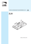
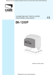
SERIE
VER
Documentazione
Tecnica
T44
rev. 1.0
V900E
02 / 2004
©
CAME
CANCELLI AUTOMATICI
119ET44-GB
CANCELLI AUTOMATICI
AUTOMATIC TRACTION SYSTEM FOR OVERHEAD AND SECTIONAL DOORS
Standar installation
7
1
8
230V~
3x1,5
2
9
10
T RG58
2x1,5
4
11
6x1,5
2x1
2x1
TX
5
4x1
RX
6
1
2
3
4
5
6
- VER unit
- Incorporated control panel
- Radio receiver
- Internal pushbutton array
- Safety photocells
- Rubber safety section
6
7 - Transmission arm
8 - Release mechanism
9 - Antenna
10 - Flashing light
11 - Key-operated selector switch
3
GENERAL SPECIFICATIONS
Description
Completion accessories
Automatic traction system for overhead and sectional doors.
Designed and built entirety by CAME Cancelli automatici
S.p.A., in full compliance with current safety standards. IP 40
protecting rating.
Guaranteed for 24 months, unless tampered with by
unauthorized personnel.
V201 - Transmission adapter arm for counterweighted
overhead doors (it substitutes the arm supplied), see p.5.
Versions
V900E - Encoder controlled 24V (D.C.) gearmotor with built-in
control panel; 230V AC power with 50÷60Hz frequency; 130W
max. motor power and up to 500N in traction power.
Sliding rails
V0679 - Rain unit with chain L=3,02 m:
- for counterweighted overhead doors up to 2,40 m height;
- for spring-balanced overhead doors up to 2,25 m height;
- for sectional doors* up to 2,20 m height
Optional accessories
V121 - Cable release device and transmission for connection
to the lock.
V122 - Improved transmissionarm for sectional gates, see pg.
5;
Attention! to insure easy installation and conformance with
current safety, norms, we raccomend installation of CAME
safety and control accessories.
* see page 4.
TECHNICAL SPECIFICATIONS
GEAR MOTOR
POWER SUPPLY
MOTOR ABSORPTION
POWER
TRACTION FORCE
DUTY CYCLE
AVERAGE SPEED
WEIGHT
V900E
230V a.c.
6A max.
130W max.
500N
50 %
6 m/min
5,7 kg
24V DC gear motor; reduction gear unit housed in a die-cast aluminium casing. The unit features an irreversible reduction gear with
worm screw and helicoidal. Permanently lubricated with liquid grease.
ABS automation container and cover with window for lamp to illuminate the area. The unit is mounted on and supported by the
sliding rail.
Built-in electric control panel.
Electronically run (Encoder) end-stop.
Galvanised cold-formed plate sliding rail; front tensioning and fastening wall terminal; ABS back motor unit support and connector
terminal. The rail has a built-in emergency release device and the transmission arm’s hook; the rail has holes for possible connection
of additional brackets.
Chain sliding system.
400
212
140
18
EXTERNAL DIMENSIONS
* For heights exceting 540 mm, it is necessary
to use additional brackets or struts.
2
540 max*
Cable exit
EXEMPLES OF APPLICATIONS
COUNTERWEIGHTED OVERHEAD DOOR,
outward vertical stroke and partially inward
entry type
A
*
H
SPRING-BALANCED OVERHEAD DOOR,
spring balanced, outward vertical stroke
and totally inward entry type
B
H
SECTIONAL DOOR
C
single sliding rail
double sliding rail
H
H - 100mm
H
UNIT ASSEMBLY
PREARRANGEMENT OF TRANSMISSION RAIL
- Fasten the bracket to the transmission guide’s
front terminal with the screws provided;
M6
M6x20
3
TRANSMISSION RAIL FASTENING
- Fasten the transmission rail in the following manner:
a) for sectional doors C-type (see ref. p.4), fasten the bracket directly over the spring-release coiling shaft using adequate dowels
and screws; if the distance between the coiling shaft and the gate’s upper ledge is between 30 and 60 cm, apply the V122 arm (read
the technical documentation provided with the accessory);
b) for A-B-type overhead doors (see ref. p.4), verify the maximum door sliding point (fig.2) and consequently fasten the bracket on
high with adequate screws or rivets.
N.B.: for counterweighted overhead doors, partial entry, it is necessary to use the adapter arm V201 (read the technical
documentation provided with the accessory).
- Raise and set the guide horizontally to establish the distance from the ceiling; then fasten the angle sections or fastening brackets
provided (cutting off any excess part) to the rail’s back terminal. N.B. the transmission guide has three ø7 holes for further fastening
should it prove necessary to reinforce the unit.
- Lift, level and fix the rail to the ceiling.
- Prepare the chase for electric wiring.
20 ÷ 30 mm
Fig.1
V122
=
30 ÷ 60 cm
=
Spring-bar
=
Upper
edge of
door
Fig.2
10 ÷ 20 mm
Spring-bar
=
Level
V201
M6
M6x14
ø7
4
SLIDING LEVER FASTENING
- Centrally fix the transmission arm to the door’s upper crosspiece with the rivets provided (or possible screws);
- Move the sliding runner and hook it to the transmission arm after removing the preset screw.
N.B.: if the adapter arm (V201) is used, hook the carriage to the sliding runner.
GEARMOTOR INSTALLATION
- Remove the automation container cover by unscrewing the ø3.9x13 screw;
- Fasten the gear motor to the sliding rail’s back terminal in the desired position with the three ø6.3x45 screws provided;
CAME
ø3,9x13
ø6,3x45
RELEASING THE GEARMOTOR
- Turn the release handle as illustrated; the release will re-hitch automatically at the first manoeuvre, by returning the lever to its
start position.
- If there is a V121 cable release device (read the technical documentation accompanying the accessory for assembly instructions),
turn the handle as illustrated to lock and the gearmotor.
V121
Release
Engage
5
ZL56 CONTROL PANEL
Technical description
The card is powered with a 230V (AC) power outlet and its
input is protected with a 1.6A line fuse. The motor is protected
with a 7,5A fuse. Control systems are powered by low voltage
and protected by a 315mA fuse. The total power consumption
of 24V accessories (which are protected by a 3.15A fuse) must
not exceed 40W.
Fixed operating time of 80 sec.
- Type of command:
-«open-stop-close-stop»
transmitter;
Safety
Photocells can be connected to obtain:
- Re-opening during the closing cycle (2-C1), the photocells
on detecting an obstacle while closing the door, cause the
movement direction to be reversed until opening is complete;
- Total stop (1-2), stop of the garage-type door with the
exclusion of the automatic closing cycle. To resume the
movement, use the pushbutton or the radio control;
- Amperometric safety device: when an obstacle is
encountered, the amperometric device causes the reversal of
movement direction during both opening and closing.
N.B.: if an obstacle is detected three times, the door wing stops
during aperture, and automatic closure is disactivated.
Use the keyboard or the radio transmitter to resume movement
of the bar.
Optional accessories
- Flashing signal light when gate is in motion (24V-25W max.),
connect it to terminal blocks 10-E;
- AF radiofrequency board (see table on pg. 24) for remote
control.
for
pushbutton
and
Accessories connected
- Courtesy Light (24V-25W). A light that illuminates the
manoeuvring zone; after an opening command, the light
remains on for a fixed time of 2 minutes and 30 seconds.
Adjustments
- Trimmer TCA = adjustment automatic closing time;
- Trimmer SENS = adjustment sensitivity of amperometric
safety system.
Important: after powering up the system or after a total-stop,
the 1st movement is always the opening manoeuvre. During
this stage it is not possible to close the door. It is possible to
re-close it after the door completes the opening manoeuvre.
Other functions
- Automatic closing. The automatic closing timer is automatically
activated at the end of the opening cycle. The preset,
adjustable automatic closing time is automatically interrupted
by the activation of any safety system, and is deactivated after
a STOP command or in case of power failure;
Caution! Shut off the mains power and disconnect the
batteries before servicing the inside of the unit.
MAIN COMPONENTS
1 - Line fuse, 1,6A
2 - Location for emergency batteries
3 - Gearmotor
4 - Transformer
5 - Transformer connection terminal board
6 - Motor fuse, 7,5A
7 - Gearmotor and encoder connection terminal board
8 - Functions control LED
9 - Buttons for saving radio code, manoeuvre and encoder
14
VERDE - GREEN - VERT - GRÜN - VERDE
ROSSO - RED - ROUGE - ROT - ROJO
5
26V17V 0V
FUS. CENTR.
315mA
15
M N
+ E -
7
BIANCO - WHITE - BLANC - WEIß - BLANCO
MARRONE - BROWN - MARRON - BRAUN - CASTAÑO
VERDE - GREEN - VERT - GRÜN - VERDE
1 2
ON
SENS.
0
17
APRE ENC/RADIO
9
4
26
AP / CH
AF
8
0V
T.C.A.
11
VERDE/GIALLO - GREEN/YELLOW - VERT/JAUNE
GRÜN/GELB - VERDE/AMARILLO
230V
10
NERO - BLACK - NOIR - SCHWARZ - NEGRO
ROSSO - RED - ROUGE - ROT - ROJO
BIANCO - WHITE - BLANC - WEIß - BLANCO
16
6
3
FUS. MOTORE 7.5A
6
12
17
programming
10 - Trimmer TCA: automatic closing time adjustment
11 - Trimmer SENS: amperometric sensitivity adjustment
12 - 2-dip function switch
13 - Courtesy Light
14 - Accessoires fuse, 3,15A
15 - Central control unit fuse, 315mA
16 - Accessory and control connection terminal board
17 - “AF” radiofrequency board socket
FUS. ACC. 3,15A
ZL56
13
MARRONE - BROWN - MARRON - BRAUN - CASTÀÑO
1
radio
2
ELECTRICAL CONNECTIONS
L N
L
N
M
N
+ 10
- 11
10
E
1
2
2
C1
2
7
M N
+ E -
10 11 E 1 2
N.B. All the contacts and push-buttons
normally closed (N.C.) that are not used
must be short-circuited.
7 C1
230V (a.c.) power supply
24 (d.c.) motor
Powering accessories (max 40W)
- 24V (A.C.) with power supply at 230V (A.C.)
- 24V (D.C.) with power supply at 24V (A.C.)
24V output in motion (e.g. 25 W max. flashing light)
Pushbutton stop (N.C.)
Contact (N.C.) for «re-aperture during closure»
Pushbutton for commands (N.O.) “OPEN-STOP-CLOSE-STOP”
Antenna connection
SELECTION OF FUNCTIONS
T.C.A.
FUS. MOTORE 7.5A
26V17V 0V
SENS.
ON
+ E -
M N
AP / CH
APRE ENC/RADIO
1 2
FUS. ACC. 3,15A
1 ON - Encoder programming; it enables the procedure for
the calibration of the opening and closing end-stop.
2 Not used, keep the dip in position OFF.
FUS. CENTR.
315mA
ON
ZL56
1 2
AF
ADJUSTMENTS
T.C.A.
FUS. MOTORE 7.5A
26V17V 0V
SENS.
ON
+ E -
M N
T.C.A.
AP / CH
APRE ENC/RADIO
1 2
120"
1"
FUS. ACC. 3,15A
Trimmer T.C.A. = Automatic closing time adjustment. N.B.:
by adjusting the minimum, the automatic closure function
is excluded.
FUS. CENTR.
315mA
ZL56
Trimmer SENS. = Amperometric sensitivity adjustment.
SENS.
max.
min.
AF
FUNCTIONS CONTROL LED
RED LED:
- light on, memorizing of the limit-switch (encoder);
M N
ON
+ E -
SENS.
AP / CH
APRE ENC/RADIO
1 2
Red led
FUS. ACC. 3,15A
- slow intermittent light, memorizing of the radio board and
automatic-closing count;
T.C.A.
FUS. MOTORE 7.5A
26V17V 0V
FUS. CENTR.
315mA
ZL56
Green led
- rapid intermittent light, signals the presence of an obstacle
or an anomaly on the device connected to contacts 2-C1.
AF
GREEN LED:
- constant light, signals the power supply in the control
board (goes off when power not supplied and each time the
total stop button is pressed).
7
ENCODER PROGRAMMING
IMPORTANT: READ INSTRUCTIONS CAREFULLY BEFORE PROCEEDING WITH PROGRAMMING.
closure limit switch
Set dip-switch 1 to ON: the red LED comes on, at slow intermittence.
Keep the “AP-CH” button pressed and allow the overhead door to reach the limit switch when it closes.
Press and release the “ENC/RADIO” button: the signalling LED remains on to indicate thet the closing end-stop has been saved.
T.C.A.
FUS. MOTORE 7.5A
M N
+ E -
SENS.
AP / CH
APRE ENC/RADIO
1 2
FUS. ACC. 3,15A
26V17V 0V
ON
FUS. CENTR.
315mA
ZL56
AF
T.C.A.
FUS. MOTORE 7.5A
+ E -
M N
AP / CH
APRE ENC/RADIO
1 2
FUS. ACC. 3,15A
26V17V 0V
SENS.
ON
FUS. CENTR.
315mA
ZL56
AF
T.C.A.
FUS. MOTORE 7.5A
M N
+ E -
SENS.
AP / CH
APRE ENC/RADIO
1 2
FUS. ACC. 3,15A
26V17V 0V
ON
FUS. CENTR.
315mA
ZL56
AF
8
opening limit switch
Keep the “APRE” button pressed and allow the door to open fully.
Press and release the “ENC/RADIO” button: the signalling LED remains on to indicate that the closing end-stop has been saved.
With the door open, position the end-stop (in the transmission guide) on the sliding runner and secure it with the screws.
Set dip-switch 1 to OFF.
Note: if the LED indicator begins to flash rapidly after dip 1 has been reset, it is necessary to repeat the procedure from the start.
NOTES
After having programmed and switched dip 1 to OFF, use the “AP/CH” key to check proper gate opening and closing.
During programming, make sure the closing end-stop has been previously memorised, otherwise the data will not be memorised.
Should the encoder malfunction or were it incorrectly connected to the opening or closing control, the motor will move briefly
and then stop. The LED indicator will indicate the irregularity by flashing slowly and continuously. In this case it is necessary to
disconnect power supply from the control panel and then reconnect it.
T.C.A.
ON
AP / CH
T.C.A.
FUS. MOTORE 7.5A
APRE ENC/RADIO
1 2
AP / CH
APRE ENC/RADIO
1 2
+ E -
M N
SENS.
FUS. ACC. 3,15A
26V17V 0V
ON
FUS. CENTR.
315mA
ZL56
AF
AF
T.C.A.
FUS. MOTORE 7.5A
26V17V 0V
M N
ON
+ E -
SENS.
AP / CH
APRE ENC/RADIO
1 2
FUS. ACC. 3,15A
E -
SENS.
FUS. CENTR.
315mA
ZL56
AF
9
RADIO CONTROL INSTALLATION
PROCEDURE
A - Insert an AF card**.
B - Encode transmitter/s.
C - Store code in the motherboard.
A - AF board insertion
T.C.A.
FUS. MOTORE 7.5A
+ E -
M N
AP / CH
APRE ENC/RADIO
1 2
TOP
AF board
TAM
FUS. ACC. 3,15A
26V17V 0V
SENS.
ON
FUS. CENTR.
315mA
ZL56
(**) On AM transmitters operating at 433.92
MHz (TOP and TAM series), position the jumper
connection on circuit card AF43S as shown on the
sheet.
Motherboard
AF
Frequency / MHz
Radiofrequency board
Transmitter
FM 26.995
AF130
TFM
FM 30.900
AF150
TFM
AF43S / AF43SM
TAM / TOP**
AF43SR
ATOMO
AM433.92
The AF board should ALWAYS be inserted
when the power is off because the motherboard
only recognises it when it is powered.
B - Transmitter encoding
TAM
ATOMO
TFM
T132
T134
T138
T432
T434
T438
AT01 - AT02 - AT04
see instruction sheet
inside the pack of
AF43SR circuit card
see instruction
sheet inside the
pack
T152
T154
T158
TOP
T434M - T314M
P1
P2
P3
P4
T432S
T432SA - T434MA
set code only
1
2
3
4
5
6
7
8
9
10
see instructions on pack
10
TOP
T432M - T312M
set the code to dip-switch C and channel to D (P1=CH1 and P2=CH2, default
setting)
P1
D
P2
P1
1
2
3
1
4
CH1
1
2
3
4
5
6
7
8
1
2
3
CH3
CH2
2
1
4
3
4
CH4
P2
C
1
4
4
3
2
3
2
9
1
2
3
4
1
2
3
1
4
10
CH1
2
3
CH3
CH2
2
1
4
3
4
CH4
C - Code storage
- Keep the “ENC/RADIO” key pressed on the base card (the signal LED will flash), and with a key on the transmitter the code is sent,
the LED will remain lit to signal the successful saving of the code.
N.B.: if you wish to change the code on your transmitters in the future, simply repeat the procedure described above.
Signal LED
T.C.A.
FUS. MOTORE 7.5A
M N
+ E -
SENS.
APRE ENC/RADIO
AP / CH
1 2
26V17V 0V
M N
T.C.A.
FUS. MOTORE 7.5A
ON
+ E -
SENS.
AP / CH
APRE ENC/RADIO
1 2
FUS. ACC. 3,15A
FUS. ACC. 3,15A
26V17V 0V
ON
FUS. CENTR.
315mA
FUS. CENTR.
315mA
ZL56
ZL56
AF
AF
AF radiofrequency board
PERIODIC MAINTENANCE
The unit does not require specific maintenance. However, it is a good idea to periodically oil the sliding wheels and the pins of the
door arms, and to check the chain’s tension.
11
MANUFACTURER’S DECLARATION
As per Enclosure II B of Machinery Directive 98/37/CE
Enclosed with the technical documentation (the original copy of the Declaration is available on request)
Date of the present declaration 07/12/2001
Also, they furthermore represent and warrant that the product/s that are the subject of the present
Declaration are manufactured in the respect of the following main harmonized provisions:
The representatives of
CAME Cancelli Automatici S.p.A.
via Martiri della Libertà, 15
31030Dosson di Casier - Treviso - ITALYtel
(+39) 0422 4940 - fax (+39) 0422 4941
internet: www.came.it - e-mail: [email protected]
Hereby declare, under their own respons ibility, that the product/s called ...
V900E
EN 292 PART 1 AND 2
EN 12453
EN 12445
EN 60335 - 1
EN 60204 - 1
EN 50081 - 1 AND 2
EN 50082 - 1 AND 2
MACHINERY SAFETY.
INDUSTRIAL, COMMERCIAL AND OTHER CLOSING MECHANISMS.
INDUSTRIAL, COMMERCIAL AND OTHER CLOSING MECHANISMS.
SAFETY IN APPARATUSES FOR HOME USE.
MACHINERY SAFETY.
ELECTROMAGNETIC COMPATIBILITY.
ELECTROMAGNETIC COMPATIBILITY.
IMPORTANT CAUTION!
It is forbidden to market/use product/s that are the subject of this declaration before completing
and/or incorporating them in total compliance with the provisions of Machinery Directive 98/37/
CE
V0679 V201 V121 V122
… comply with the Italian National Legal Provisions that transpose the
following Community Directives (where specifically applicable):
MACHINERY DIRECTIVE 98/37/CE
LOW VOLTAGE DIRECTIVE 73/23/EEC - 93/68/EEC
LECTROMAGNETIC COMPATIBILITY DIRECTIVE 89/336/EEC - 92/31/EEC
R&TTE DIRECTIVE 1999/5/CE
Signatures of the Representatives
TECHNICAL MANAGER
Mr. Gianni Michielan
MANAGING DIRECTOR
Mr. Paolo Menuzzo
Specific technical documentation on the products is available on request!
All data checked with the maximum care. However, no liability is accepted for any error or omission.
ASSISTENZA TECNICA
NUMERO VERDE
800 295830
CANCELLI AUTOMATICI
SISTEMA QUALITÅ
CERTIFICATO
WEB
www.came.it
E-MAIL
[email protected]
CAME CANCELLI AUTOMATICI S.P.A.
DOSSON DI CASIER (TREVISO)
(+39) 0422 4940
(+39) 0422 4941
CAME LOMBARDIA S.R.L._____COLOGNO M. (MI)
(+39) 02 26708293
(+39) 02 25490288
CAME SUD S.R.L. ___________________NAPOLI
(+39) 081 7524455
(+39) 081 7529109
CAME (AMERICA) L.L.C.________MIAMI (FL)
(+1) 305 5938798
(+1) 305 5939823
CAME AUTOMATISMOS S.A__________MADRID
(+34) 091 5285009
(+34) 091 4685442
CAME BELGIUM__________________LESSINES
(+32) 068 333014
(+32) 068 338019
CAME FRANCE S.A.____NANTERRE CEDEX (PARIS)
(+33) 01 46130505
(+33) 01 46130500
CAME GMBH________KORNTAL BEI (STUTTGART)
(+49) 07 15037830
(+49) 07 150378383
CAME GMBH____________SEEFELD BEI (BERLIN)
(+49) 03 33988390
(+49) 03 339885508
CAME PL SP.ZO.O______________WARSZAWA
(+48) 022 8365076
(+48) 022 8369920
CAME UNITED KINGDOM LTD___NOTTINGHAM
(+44) 0115 9210430
(+44) 0115 9210431