1
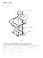
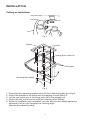
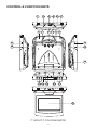
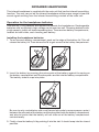
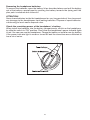
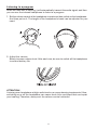
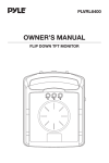
PLVWR70IR
OWNER’S MANUAL
FLIP DOWN TFT MONITOR
INSTALLATION
Desk-top Installation
Mounting Bolts (M3x6)
2
1
Tapping Screw (M4x10)
Bracket
Levers
Fig. 1
1. Determine the mounting location and drill four mounting holes.
2. Attach the bracket to the holes with the tapping screws (M4x10).
3. Let the two levers aim at the fixing holes on the bottom of the base to fix the display
unit.
4. Attach the TV unit to the preferred location with the mounting bolts (M3x6).
5. For the convenience of fixing the unit, you can turn the display left or right to show
the holes on the base.
(See the arrowhead symbol named 1).
6. When the installation has completed, you can turn the display upward or downward,
left or right to adjust the viewing angle.
(See the arrowhead symbol named 2 and 1).
2
INSTALLATION
Ceiling-on Installation
Fig. 2
Bracket
Levers
Tapping Screws (M4x10)
Fixing holes
Mounting Bolts (M3x6)
Fig. 3
1.
2.
3.
4.
5.
Determine the mounting location and drill four mounting holes (see Fig.2).
Attach the bracket to the holes with the tapping screws (M4x10).
Let the two levers aim at the fixing holes to fix the display unit.
Attach the unit to the bracket with the mounting bolts (M3x6).
When the installation has completed, you can also turn the display upward or
downward, left or right to adjust the viewing angle.
(See the arrowhead symbol).
3
REPLACING THE CAR DOME LAMP
Follow the directions show below for a new lamp changing.
1. Position light switch to “ ”.
2. Push back the lamp cover and open it. (Refer to the following figure)
3. Remove and discard the old lamp.
4. Install a new bulb.
5. Close the cover.
Lamp Cover
Bulb
Light Switch
Bulb Specification
Diameter:
ø8mm
Length:
28mm
Voltage Spec.: DC12V, 5W
CAR DOME LAMP WIRING
Line for Car Dome Lamp
Note:
Color
Connection
Red
Power Supply
White
Black
Interior Light System
Ground
4
CONTROL & FUNCTION KEYS
1
3
2
7
4
5 21 6
8 13 9 3
11
11
12
12
14
18 15 16
20
17
10
7” INCH TFT COLOR MONITOR
5
MONITOR
1. & 2. (POWER) and POWER INDICATOR LIGHT
When the unit is provided DC 12V power, press POWER button (1) to turn on
the unit. And then the power indicator light (2) will be illuminated red. Press it
again to turn it off.
3.
CAR DOME LAMP
The two car dome lamps (3) will be on in some needed situations.
4.
LIGHT SWITCH
There are three settings for the car dome lamp operation:
(OFF),
and
A.
B.
(ON), refer to light switch (4).
To turn off the lamp.
To make the lamp turned on only when car doors are opened.
C.
To turn on the lamp.
(AUTO),
6.
SPEAKER VOLUME CONTROL KNOB
Slide the switch (6) left or right to increase or decrease the volume level of the
speakers on the base of the unit. When slide the switch in the direction of
volume decreasing to the end, it will turn off the speakers.
7.
)
BRIGHT (
Rotate the bright knob (7) clockwise or counter-clockwise to increase or
decrease the screen brightness.
8.
CONTRAST ( )
Rotate the contrast knob (8) clockwise or counter-clockwise to increase or
decrease the contrast lever of the screen display.
9.
COLOR ( )
Rotate the color knob (9) clockwise or counter-clockwise to increase or
decrease the color level of the screen display.
10. TFT LIQUID CRYSTAL DISPLAY
The 7-inch color TFT LCD (10) can show the current state of the unit.
11. EARPHONE VOLUME CONTROL KNOB
Slide the knob (11) will change the volume of the earphone.
12. JACKS FOR EARPHONE
There are two jacks (12) for earphone. You can connect PLVH2 of the jacks to
receive sound signal.
6
13. PUSH (Monitor Release Button)
Opening the Monitor
Press the PUSH button (13) to eject the screen display from the base at a little
angle. Then you can easily turn the display upward or downward for good
viewing. The monitor also can be adjusted through 30 degree both left and
right from the central viewing position
Closing the Monitor
Return the monitor to the central viewing position. Then push the monitor back
into the monitor base unit until the screen engages with PUSH button (13) .
14. DISPLAY DIRECTION CONTROL SWITCH
The switch (14) should be dialled to DOWN side or UP side to adjust the
direction of the picture display and get user's needed viewing effect.
15. DC 12V INPUT
Through this jack (15), provide DC 12V power supply to the unit.
16. SENSOR
When connect DVD unit or another unit to the monitor through these two jacks
(16), you can control the DVD unit or another unit by pointing the remote control
handset directly to the remote sensor (5).
17. AV1 IN
The group of jacks (17) is used for AUDIO R in and AUDIO L in and VIDEO in.
18. AV2 IN
The group of jacks (18) is also used for AUDIO R in and AUDIO L in and VIDEO
in.
20. AV SELECT SWITCH
Slide the switch (20) to left side or right side to select between AV1 mode and
AV2 mode.
21. INFRARED TRANSMITTING WINDOW
There are six infrared transmitting lights inside the window (21), the user can
put on the infrared wireless headphones supplied with the unit and hear the
sound digital signal emitting from the window (21).
7
OWNER’S MANUAL
INFRARED HEADPHONE
8
INFRARED HEADPHONE
This infrared headphone is supplied with the main unit that has the infrared transmitting
function. The user can put on the infrared headphone within proper range to hear the
sound signal emitting from the infrared transmitting window of the main unit.
Operation for the headphone batteries
Two Size AA (1.5V) batteries are required to operate the headphones. Rechargeable
batteries with a sufficiently high voltage can be used as well. Choosing batteries with
a high capacity (mAh) will extend operating time. There are two battery compartments,
located on both sides, each housing one battery.
Installing the headphone batteries:
1. To access each battery compartment, push on the edge of the battery lid. This will
release the battery lid. Then remove the lid to gain access to the battery compartment.
2. Insert the battery by pressing the minus pole of the battery against the spring on
the battery compartment until the plus pole can slide into the battery compartment.
The battery should snap into place.
Be sure to only use batteries with a well formed plus pole to ensure proper contact
between the plus pole of the battery and the plus pole inside the battery compartment
and also to ensure that the battery will not slide out of the battery compartment
unintentionally.
3. Finally, close the battery lid by pushing it into the slot. It should snap into the closed
position.
9
Removing the headphone batteries:
To remove the batteries, open the battery lid as described above and pull the battery
out of the battery compartment by pushing the battery towards the spring until the
plus pole is released and slides out.
ATTENTION!
Never leave batteries inside the headphones for very long periods of time to prevent
any damage to the headphones from leaking batteries. Dispose of spent batteries
conforming to local waste disposal rules.
Check the remaining power of the headphone’ s battery:
When install two batteries into the battery compartments, switch on the headphone
by slide the switch to “ON” position. Check that the headphone’s power indicator lights
in red. You can now use the headphone. Charge the battery or install a new dry battery,
if the power indicator light is weak or turned off and the sound becomes distorted or
has a lot of noise.
10
Listening to a program
When the main unit is working, it will automatically transmit the audio signal, and then
you can use the infrared headphone to listen to a program.
1. Set the volume control of the headphone to minimum then switch on the headphone.
And then put on it. The length of the headphone’s band can be adjusted to your
need.
2. Adjust the volume.
Slowly increase volume level. After each use, be sure to switch off the headphone
to extend battery life.
ATTENTION!
Listening over headphone at high audio levels can cause hearing impairments! Also,
switching on or off the headphone can cause loud clicks and pops that can impair
your hearing! Therefore, always set the volume control minimum.
11
www.pyleaudio.com
88-T1342-05