1
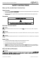
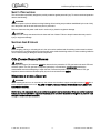
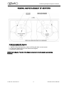
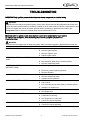
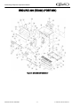
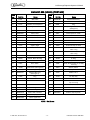
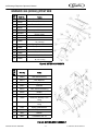
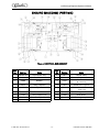
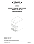
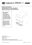
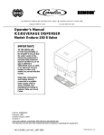
ICE/BEVERAGE DISPENSER Model: ED 300 BN Operator’s Manual Release Date: November 16, 1998 Publication Number: 620913201 Revision Date: August 3, 2010 Revision: E Visit the IMI Cornelius web site at www.cornelius.com for all your Literature needs. The products, technical information, and instructions contained in this manual are subject to change without notice. These instructions are not intended to cover all details or variations of the equipment, nor to provide for every possible contingency in the installation, operation or maintenance of this equipment. This manual assumes that the person(s) working on the equipment have been trained and are skilled in working with electrical, plumbing, pneumatic, and mechanical equipment. It is assumed that appropriate safety precautions are taken and that all local safety and construction requirements are being met, in addition to the information contained in this manual. This Product is warranted only as provided in Cornelius’ Commercial Warrant applicable to this Product and is subject to all of the restrictions and limitations contained in the Commercial Warranty. Cornelius will not be responsible for any repair, replacement or other service required by or loss or damage resulting from any of the following occurrences, including but not limited to, (1) other than normal and proper use and normal service conditions with respect to the Product, (2) improper voltage, (3) inadequate wiring, (4) abuse, (5) accident, (6) alteration, (7) misuse, (8) neglect, (9) unauthorized repair or the failure to utilize suitably qualified and trained persons to perform service and/or repair of the Product, (10) improper cleaning, (11) failure to follow installation, operating, cleaning or maintenance instructions, (12) use of “non-authorized” parts (i.e., parts that are not 100% compatible with the Product) which use voids the entire warranty, (13) Product parts in contact with water or the product dispensed which are adversely impacted by changes in liquid scale or chemical composition. Contact Information: To inquire about current revisions of this and other documentation or for assistance with any Cornelius product contact: www.cornelius.com 800-238-3600 Trademarks and Copyrights: This document contains proprietary information and it may not be reproduced in any way without permission from Cornelius. Printed in U.S.A. TABLE OF CONTENT Safety Instructions . . . . . . . . . . . . . . . . . . . . . . . . . . . . . . . . . . . . . . . . . . . . . . . . . . . . . . . . . . . . . Read and Follow ALL Safety Instructions . . . . . . . . . . . . . . . . . . . . . . . . . . . . . . . . . . . . . . . . Safety Overview . . . . . . . . . . . . . . . . . . . . . . . . . . . . . . . . . . . . . . . . . . . . . . . . . . . . . . . . Recognition. . . . . . . . . . . . . . . . . . . . . . . . . . . . . . . . . . . . . . . . . . . . . . . . . . . . . . . . . . . . Different Types of Alerts . . . . . . . . . . . . . . . . . . . . . . . . . . . . . . . . . . . . . . . . . . . . . . . . . . . . . Safety Tips . . . . . . . . . . . . . . . . . . . . . . . . . . . . . . . . . . . . . . . . . . . . . . . . . . . . . . . . . . . . . . . Qualified Service Personnel . . . . . . . . . . . . . . . . . . . . . . . . . . . . . . . . . . . . . . . . . . . . . . . . . . Safety Precautions . . . . . . . . . . . . . . . . . . . . . . . . . . . . . . . . . . . . . . . . . . . . . . . . . . . . . . . . . Shipping And Storage . . . . . . . . . . . . . . . . . . . . . . . . . . . . . . . . . . . . . . . . . . . . . . . . . . . . . . . CO2 (Carbon Dioxide) Warning . . . . . . . . . . . . . . . . . . . . . . . . . . . . . . . . . . . . . . . . . . . . . . . Mounting in or on a Counter . . . . . . . . . . . . . . . . . . . . . . . . . . . . . . . . . . . . . . . . . . . . . . . . . . 1 1 1 1 1 1 1 2 2 2 2 Start-up and Operating Instructions. . . . . . . . . . . . . . . . . . . . . . . . . . . . . . . . . . . . . . . . . . . . . . . . 3 Ice Drink Dispenser. . . . . . . . . . . . . . . . . . . . . . . . . . . . . . . . . . . . . . . . . . . . . . . . . . . . . . . . . 3 Cleaning And Maintenance Instructions . . . . . . . . . . . . . . . . . . . . . . . . . . . . . . . . . . . . . . . . . . . Daily Cleaning: . . . . . . . . . . . . . . . . . . . . . . . . . . . . . . . . . . . . . . . . . . . . . . . . . . . . . . . . . . . Daily Maintenance: . . . . . . . . . . . . . . . . . . . . . . . . . . . . . . . . . . . . . . . . . . . . . . . . . . . . . . . . Weekly Cleaning: (In addition to daily procedures) . . . . . . . . . . . . . . . . . . . . . . . . . . . . . . . Monthly Cleaning: (In addition to daily and weekly procedures) . . . . . . . . . . . . . . . . . . . . . . Yearly Maintenance: . . . . . . . . . . . . . . . . . . . . . . . . . . . . . . . . . . . . . . . . . . . . . . . . . . . . . . . Cleaning Interior Surfaces (Monthly Cleaning) . . . . . . . . . . . . . . . . . . . . . . . . . . . . . . . . . . . Cold Plate (Yearly Maintenance). . . . . . . . . . . . . . . . . . . . . . . . . . . . . . . . . . . . . . . . . . . . . . Dispensing Valves: ( Daily Cleaning) . . . . . . . . . . . . . . . . . . . . . . . . . . . . . . . . . . . . . . . . . . Product Tubing (Monthly Cleaning) . . . . . . . . . . . . . . . . . . . . . . . . . . . . . . . . . . . . . . . . . . . . Sanitize Pre-Mix And Post–Mix Tank System . . . . . . . . . . . . . . . . . . . . . . . . . . . . . . . . . . Sanitize syrup lines, B–I–B Systems . . . . . . . . . . . . . . . . . . . . . . . . . . . . . . . . . . . . . . . . . Replenishing CO2 Supply (As Required) . . . . . . . . . . . . . . . . . . . . . . . . . . . . . . . . . . . . . . . 4 4 4 4 5 5 5 5 6 6 6 6 7 Removal And Replacement Of Agitators . . . . . . . . . . . . . . . . . . . . . . . . . . . . . . . . . . . . . . . . . . . . 8 To Remove Agitators For Cleaning. . . . . . . . . . . . . . . . . . . . . . . . . . . . . . . . . . . . . . . . . . . . . 8 Troubleshooting . . . . . . . . . . . . . . . . . . . . . . . . . . . . . . . . . . . . . . . . . . . . . . . . . . . . . . . . . . . . . . . 9 Blown Fuse Or Circuit Breaker.. . . . . . . . . . . . . . . . . . . . . . . . . . . . . . . . . . . . . . . . . . . . . . . . 9 Gate Does Not Open. Agitator Does Not Turn.. . . . . . . . . . . . . . . . . . . . . . . . . . . . . . . . . . . . 9 Gate Does Not Open Or Is Sluggish Agitator Turns . . . . . . . . . . . . . . . . . . . . . . . . . . . . . . . .. 9 Ice Dispenses Continuously. . . . . . . . . . . . . . . . . . . . . . . . . . . . . . . . . . . . . . . . . . . . . . . . . . 9 Beverages Do Not Dispense. . . . . . . . . . . . . . . . . . . . . . . . . . . . . . . . . . . . . . . . . . . . . . . . . . 9 Beverages Too Sweet. . . . . . . . . . . . . . . . . . . . . . . . . . . . . . . . . . . . . . . . . . . . . . . . . . . . . . . 9 Beverage Not Sweet Enough.. . . . . . . . . . . . . . . . . . . . . . . . . . . . . . . . . . . . . . . . . . . . . . . . . 9 Agitators Turn In Opposite Directions . . . . . . . . . . . . . . . . . . . . . . . . . . . . . . . . . . . . . . . . . . . 9 Ice does not dispense from one gate assembly . . . . . . . . . . . . . . . . . . . . . . . . . . . . . . . . . . 10 LIST OF FIGURES FIGURE 1. ENDURO 300 ASSEMBLY . . . . . . . . . . . . . . . . . . . . . . . . . . . . . . . . . . . . . . . . . . . . 11 FIGURE 2. MOTER COMPONENT . . . . . . . . . . . . . . . . . . . . . . . . . . . . . . . . . . . . . . . . . . . . . . . 13 FIGURE 3. GATE SOLENOID ASSEMBLY. . . . . . . . . . . . . . . . . . . . . . . . . . . . . . . . . . . . . . . . . 13 FIGURE 4. ELECTRICAL BOX ASSEMBLY . . . . . . . . . . . . . . . . . . . . . . . . . . . . . . . . . . . . . . . . 14 FIGURE 5. VALVE PANEL ASSEMBLY . . . . . . . . . . . . . . . . . . . . . . . . . . . . . . . . . . . . . . . . . . . 15 FIGURE 6. GLADDER SCHEMATIC. . . . . . . . . . . . . . . . . . . . . . . . . . . . . . . . . . . . . . . . . . . . . . 16 Ice/Beverage Dispenser Operator’s Manual SAFETY INSTRUCTIONS READ AND FOLLOW ALL SAFETY INSTRUCTIONS Safety Overview • Read and follow ALL SAFETY INSTRUCTIONS in this manual and any warning/caution labels on the unit (decals, labels or laminated cards). • Read and understand ALL applicable OSHA (Occupational Safety and Health Administration) safety regulations before operating this unit. Recognition Recognize Safety Alerts ! This is the safety alert symbol. When you see it in this manual or on the unit, be alert to the potential of personal injury or damage to the unit. DIFFERENT TYPES OF ALERTS ! DANGER: Indicates an immediate hazardous situation which if not avoided WILL result in serious injury, death or equipment damage. ! WARNING: Indicates a potentially hazardous situation which, if not avoided, COULD result in serious injury, death, or equipment damage. ! CAUTION: Indicates a potentially hazardous situation which, if not avoided, MAY result in minor or moderate injury or equipment damage. SAFETY TIPS • Carefully read and follow all safety messages in this manual and safety signs on the unit. • Keep safety signs in good condition and replace missing or damaged items. • Learn how to operate the unit and how to use the controls properly. • Do not let anyone operate the unit without proper training. This appliance is not intended for use by very young children or infirm persons without supervision. Young children should be supervised to ensure that they do not play with the appliance. • Keep your unit in proper working condition and do not allow unauthorized modifications to the unit. QUALIFIED SERVICE PERSONNEL ! WARNING: Only trained and certified electrical, plumbing and refrigeration technicians should service this unit. ALL WIRING AND PLUMBING MUST CONFORM TO NATIONAL AND LOCAL CODES. FAILURE TO COMPLY COULD RESULT IN SERIOUS INJURY, DEATH OR EQUIPMENT DAMAGE. Publication Number: 620913201 -1- © 1998-2010, IMI Cornelius Inc. Ice/Beverage Dispenser Operator’s Manual SAFETY PRECAUTIONS This unit has been specifically designed to provide protection against personal injury. To ensure continued protection observe the following: ! WARNING: Disconnect power to the unit before servicing following all lock out/tag out procedures established by the user. Verify all of the power is off to the unit before any work is performed. Failure to disconnect the power could result in serious injury, death or equipment damage. ! CAUTION: Always be sure to keep area around the unit clean and free of clutter. Failure to keep this area clean may result in injury or equipment damage. SHIPPING AND STORAGE ! CAUTION: Before shipping, storing, or relocating the unit, the unit must be sanitized and all sanitizing solution must be drained from the system. A freezing ambient environment will cause residual sanitizing solution or water remaining inside the unit to freeze resulting in damage to internal components. CO2 (CARBON DIOXIDE) WARNING ! DANGER: CO2 displaces oxygen. Strict attention MUST be observed in the prevention of CO2 gas leaks in the entire CO2 and soft drink system. If a CO2 gas leak is suspected, particularly in a small area, IMMEDIATELY ventilate the contaminated area before attempting to repair the leak. Personnel exposed to high concentrations of CO2 gas experience tremors which are followed rapidly by loss of consciousness and DEATH. MOUNTING IN OR ON A COUNTER ! WARNING: When installing the unit in or on a counter top, the counter must be able to support a weight in excess of XXX lbs. to insure adequate support for the unit. FAILURE TO COMPLY COULD RESULT IN SERIOUS INJURY, DEATH OR EQUIPMENT DAMAGE. NOTE: Many units incorporate the use of additional equipment such as icemakers. When any addition equipment is used you must check with the equipment manufacturer to determine the additional weight the counter will need to support to ensure a safe installation. © 1998-2010, IMI Cornelius Inc. -2- Publication Number: 620913201 Ice/Beverage Dispenser Operator’s Manual START-UP AND OPERATING INSTRUCTIONS ICE DRINK DISPENSER The ice drink dispenser shall be installed by qualified personnel following instruction given in the Installation manual part number 620913201INS. Fill the hopper with ice. Dispense several large cups of ice (approximately 20 to 30 seconds total dispensing time) to allow ice to fill the cold plate cabinet. Add ice to the hopper as necessary to refill, then replace the lid. Allow 10 to 15 minutes for the cold plate to cool down. Repeat this procedure whenever the dispenser has run out of ice. Start up the beverage system and adjust faucets to the proper brix. Contact your local syrup distributor for complete information on the beverage system. The ice drink dispenser is designed to operate in ambient temperatures ranging from 40 to 105o F. Do not allow the unit to be stored or operated in conditions below 32o F. This could cause damage to the unit. ! CAUTION: Dispenser cannot be used with crushed or flaked ice. Use of bagged ice which has frozen into large chunks can void warranty. The dispenser agitator is not designed to be an ice crusher. Use of large chunks of ice which “jam up” inside the hopper will cause failure if the agitator motor and damage to the hopper. If bagged ice is used, it must be carefully and completely broken into small, cube-sized pieces and left to “temper” or warm up for a minimum of 20 minutes in room temperature before loading into the dispenser hopper In normal operation, pushing the ice dispenser mechanism will cause ice to flow from the ice chute. Ice flow will continue until the dispenser mechanism is released. Dispensing of any faucet will provide beverage of the appropriate flavor. ! WARNING: Use caution to avoid spilling ice when filling dispenser. Clean up immediately any spilled ice from filling or operating the unit. To prevent contamination of ice, the lid must be installed on the unit at all times. FAILURE TO CLEAN UP SPILLS COULD RESULT IN SERIOUS INJURY OR DEATH If the dispenser fails to dispense ice or beverage, refer to the troubleshooting section in the Installation Manual part number 620913201INS. NOTE: The dispenser is not designed for a wash-down environment and MUST NOT be placed in an area where a water jet could be used. NOTE: This appliance is not intended for use by personnel (including children) with reduced physical, sensory or mental capabilities or lack of experience and knowledge, unless given supervision or instruction concerning use of the appliance by a person responsible for safety. Publication Number: 620913201 -3- © 1998-2010, IMI Cornelius Inc. Ice/Beverage Dispenser Operator’s Manual CLEANING AND MAINTENANCE INSTRUCTIONS These instructions are used on all Cornelius ice drink dispensers. Some models may have additional cleaning requirements. Those models will have addition procedures listed later in the manual. ! WARNING: Disconnect power to the unit before cleaning or servicing following all lock out / tag out procedures established by the user. Verify all of the power is off to the unit before performing any work. Failure to comply could result in serious injury, death or damage to the equipment. ! CAUTION: Do not use metal scrapers, sharp objects or abrasives on the ice storage hopper, top cover, agitator disc or exterior surfaces as damage to the unit may result. Do not use solvents or other cleaning agents as they may attack the material resulting in damage to the unit. Soap solution – Use a mixture of mild detergent and warm (100° F ) potable water. Sanitizing Solution – Dissolve 2 packets (4 oz) of Stera Sheen Green Label into 2 gallons of warm (80 – 100° F) potable water to ensure 200 ppm of chlorine. Daily Cleaning: 1. Remove cup rest from drip tray and clean with warm soapy water, rinse with clean water and allow to air dry. 2. Wipe down the exterior of the unit with warm soapy water, rinse with clean water and allow to air dry. 3. Remove valve nozzles and diffusers and wash in warm soapy water, rinse in clean water and allow to air dry. 4. Clean the interior of the ice chute using the brush provided with the unit with warm soapy water, rinse with clean water and allow to air dry. 5. Spray the ice chute inside and out with sanitizer and allow to air dry. 6. Pour warm soapy water down the drains to keep them clean and flowing smoothly. 7. Spray the nozzles and diffusers inside and outside with approved sanitizing solution, reinstall them on the valves and allow to air dry. 8. Reinstall the cup rest into the drip tray. 9. Pour all remaining sanitizer solution down the drains to help keep the drain clear. Daily Maintenance: 1. Check the temperature, smell and taste of the product. 2. Check the water pressure coming to the unit using the pressure gauges on the back room package. 3. Check carbonation of the drink 4. Check level of CO2 supply to the system. 5. Check the date on all of the BIB’s (bags in boxes). Weekly Cleaning: (In addition to daily procedures) Remove the ice chute cover and clean it along with the back half with warm soapy using the brush provided with the unit. Rinse with clean water and reinstall on the unit. Spray the ice chute assembly with approved sanitizer allowing it to air dry. © 1998-2010, IMI Cornelius Inc. -4- Publication Number: 620913201 Ice/Beverage Dispenser Operator’s Manual Monthly Cleaning: (In addition to daily and weekly procedures) 1. Flush and sanitize all syrup lines as well as all of the syrup connectors. (See the sanitize syrup lines section shown later in this manual). 2. Remove ice from hopper and clean and sanitize the hopper. (See the Cleaning the interior surfaces section shown later in this manual). 3. While cleaning the hopper use the brush provided with the unit to clean the cold plate surface. To accomplish this, the brush needs to be extended through the opening in the bottom of the hopper. Yearly Maintenance: Have the water pump and check valve inspected and cleaned by a qualified service technician. Have the CO2 gas check valve inspected and cleaned by a qualified service technician. Remove the unit’s splash and cold plate cover to clean and sanitize the cold plate surface. (See the cleaning the cold plate section shown later in this manual). Cleaning Interior Surfaces (Monthly Cleaning) ! CAUTION: When pouring liquid into the hopper, do not exceed the rate of 1/2 gallon per minute. Pouring more liquid into the hopper could result in an overflow situation may result in injury or damage to the equipment. 1. Remove agitator assembly. 2. Using a nylon bristle brush or sponge, clean the interior of the hopper, top cover and agitator assembly with soap solution. Thoroughly rinse the hopper, cover and agitator surfaces with clean potable water. 3. Reassemble agitator assembly. Take special care to ensure that the thumbscrew is tight. 4. Using a mechanical spray bottle filled with sanitizing solution, spray the entire interior and agitator assembly. Allow to air dry. 5. Remove merchandiser and ice chute cover from unit. 6. With a nylon bristle brush or sponge, clean the inside of the ice chute, gasket, and cover with soap solution and rinse thoroughly to remove all traces of detergent. 7. Reassemble ice chute assembly. 8. Using a mechanical spray bottle filled with sanitizing solution, spray the inside of the ice chute. Allow to air dry. 9. Reinstall merchandiser. Cold Plate (Yearly Maintenance) 1. 2. 3. 4. 5. 6. 7. 8. Remove splash panel. Remove or move the plastic cold plate cover to expose the cold plate. Locate and remove any debris from the drain trough. Check that the drain holes are not clogged. Pour small amount of soap solution through cold plate openings in hopper. Using a cloth, wash down the surfaces of the cold plate and plastic cover with soap solution. Install and properly position the access covers on the cold plate. Install the splash panel in the reverse order it was removed. Rinse cold plate surface by pouring potable water through hopper openings. Publication Number: 620913201 -5- © 1998-2010, IMI Cornelius Inc. Ice/Beverage Dispenser Operator’s Manual Dispensing Valves: ( Daily Cleaning) Refer to addendum supplied with the unit that is applicable to the manufacturer of the valves installed on the unit. Product Tubing (Monthly Cleaning) IMPORTANT: Only trained and qualified persons should perform these cleaning and sanitizing procedures. Sanitize Pre-Mix And Post–Mix Tank System 1. Remove all the quick disconnects from all the tanks. Fill a suitable pail or bucket with soap solution. 2. Submerge all disconnects (gas and liquid) in the soap solution and then clean them using a nylon bristle brush. (Do not use a wire brush). Rinse with clean water. 3. Prepare sanitizing solution and using a mechanical spray bottle, spray the disconnects. Allow to air dry. 4. Using a clean, empty tank, prepare five (5) gallons of the sanitizing solution. Rinse the tank disconnects with approximately 9 oz. of the sanitizing solution. Close the tank. 5. Prepare cleaning tank by filling clean five (5) gallon tank with a mixture of mild detergent and potable water (120oF). 6. Connect a gas disconnect to the tank and then apply one of the product tubes to the cleaning tank. Operate the appropriate valve until liquid dispensed is free of any syrup. 7. Disconnect cleaning tank and hook up sanitizing tank to syrup line and CO2 system. 8. Energize beverage faucet until chlorine sanitizing solution is dispensed through the faucet. Flush at least two (2) cups of liquid to ensure that the sanitizing solution has filled the entire length of the syrup tubing. 9. Allow sanitizer to remain in lines for fifteen (15) minutes. 10. Repeat the step above, applying a different product tube each time until all tubes are filled with the sanitizing solution. 11. Remove the nozzle and syrup diffuser and clean them in a mild soap solution. Rinse with clean water and reassemble the nozzle and syrup diffuser on the valve. 12. Rinse the parts in clean water, reassemble the valve and reconnect it to the dispenser. 13. Discard the tank of sanitizing solution and reconnect the product syrup tanks. Operate the valves until all sanitizer has been flushed from the system and only product syrup is flowing. Sanitize syrup lines, B–I–B Systems 1. Remove all the quick disconnects from all the B–I–B containers. 2. Fill a suitable pail or bucket with soap solution. 3. Submerge all disconnects (gas and liquid) in the soap solution and then clean them using a nylon bristle brush. (Do not use a wire brush). Rinse with clean water. 4. Using a plastic pail, prepare approximately five (5) gallons of sanitizing solution. 5. Rinse the B–I–B disconnects in the sanitizing solution. 6. Sanitizing fittings must be attached to each B–I–B disconnect. If these fittings are not available, the fittings from empty B–I–B bags can be cut from the bags and used. These fittings open the disconnect so the sanitizing solution can be drawn through the disconnect. 7. Place all the B–I–B disconnects into the pail of sanitizing solution. Operate all the valves until the sanitizing solution is flowing from the valve. Allow sanitizer to remain in lines for fifteen (15) minutes. 8. Remove the nozzle and syrup diffuser from each valve and clean them in a soap solution. Rinse with clean water and reassemble the nozzle and syrup diffuser to the valve. 9. Remove the sanitizing fittings from the B–I–B disconnects and connect the disconnects to the appropriate B–I–B container. Operate the valves until all sanitizer has been flushed from the system and syrup is flowing freely. © 1998-2010, IMI Cornelius Inc. -6- Publication Number: 620913201 Ice/Beverage Dispenser Operator’s Manual Replenishing CO2 Supply (As Required) NOTE:When indicator on the 1800-psi gage is in the shaded (“change CO2 cylinder”) portion of the dial, CO2 cylinder is almost empty and should be changed. 1. Fully close (clockwise) the CO2 cylinder valve. 2. Slowly loosen the CO2 regulator assembly coupling nut allowing CO2 pressure to escape, then remove the regulator assembly from the empty CO2 cylinder. 3. Unfasten safety chain and remove the empty CO2 cylinder ! WARNING: To avoid personnel injury and/or property damage, always secure the CO2 cylinder with a safety chain to prevent it from falling over. Should the valve become accidently damaged or brokenoff, a CO2 regulator can cause serious personnel injury or death could occur. 4. Position the full CO2 cylinder and secure with a safety chain. 5. Make sure gasket is in place inside the CO2 regulator assembly coupling nut, then install the regulator assembly on the CO2 cylinder. 6. Open (counterclockwise) the CO2 cylinder valve slightly to allow the lines to slowly fill with gas, then open the valve fully to back-seat the valve (back-seating the valve prevents gas leakage around the valve shaft). 7. Check CO2 connections for leaks. Tighten any loose connections Publication Number: 620913201 -7- © 1998-2010, IMI Cornelius Inc. Ice/Beverage Dispenser Operator’s Manual REMOVAL AND REPLACEMENT OF AGITATORS To Remove Agitators For Cleaning 1. 2. 3. 4. Lift agitator and disc from unit.. Remove O-Ring starting at notch. Warm the O-Ring with water to ease removal. Lift the plastic agitator disc off of the stainless-steel agitator. Replace by reversing steps. NOTE: Refer to Sanitize Procedure in the Owners Instruction for complete cleaning and sanitizing instructions. © 1998-2010, IMI Cornelius Inc. -8- Publication Number: 620913201 Ice/Beverage Dispenser Operator’s Manual TROUBLESHOOTING IMPORTANT:Only qualified personnel should service internal components or electrical wiring. ! WARNING: If repairs are to be made to the product system, remove quick disconnects from the applicable product tank, then relieve the system pressure before proceeding. If repairs are to be made to the CO2 system, stop dispensing, shut off the CO2 supply, then relieve the system pressure before proceeding. If repairs are to be made to the refrigeration system, make sure electrical power is disconnected from the unit. Should your unit fail to operate properly, check that there is power to the unit and that the hopper contains ice. If the unit does not dispense, check the following chart under the appropriate symptoms to aid in locating the defect. ! WARNING: If repairs are to be made to the ice dispensing system, make sure electrical power is disconnected from the unit. Trouble Probable Cause A. B. C. D. GATE DOES NOT OPEN. AGITATOR DOES NOT A. TURN. B. C. GATE DOES NOT OPEN OR IS SLUGGISH. A. BLOWN FUSE OR CIRCUIT BREAKER. Short circuit in wiring. Defective gate solenoid. Defective agitator motor. Defective gate rectifier No power. Bent depressor plate (does not actuate switch). Defective dispensing switch. Defective gate solenoid. AGITATOR TURNS. ICE DISPENSES CONTINUOUSLY. SLUSHY ICE. WATER IN HOPPER. BEVERAGES DO NOT DISPENSE. B. C. A. B. C. A. B. C. D. A. B. Excessive pressure against gate slide. Defective Rectifier. Stuck or bent depressor plate (does not release switch) Defective dispensing switch Improper switch installation. Blocked drain. Unit not level. Poor ice quality due to water quality or icemark problem. Improper use of flaked ice. No 24 volt power to faucets. No CO2 pressure. BEVERAGES TOO SWEET A. Carbonator not working. B. C. BEVERAGE NOT SWEET ENOUGH. A. B. AGITATORS TURN IN OPPOSITE DIRECTIONS A. Publication Number: 620913201 No CO2 pressure in carbonator Faucet brix requires adjusting. Empty syrup tank. Faucet brix requires adjusting. This is normal and is necessary for uniform ice agitation. -9- © 1998-2010, IMI Cornelius Inc. Ice/Beverage Dispenser Operator’s Manual Trouble ICE DOES NOT DISPENSE FROM ONE GATE ASSEMBLY Probable Cause A. Agitators reversed. B. Defective gate solenoid or rectifier. C. Motors wired incorrectly Contact your local syrup or beverage equipment distributor for additional information and troubleshooting of beverage system. © 1998-2010, IMI Cornelius Inc. - 10 - Publication Number: 620913201 Ice/Beverage Dispenser Operator’s Manual ENDURO 300 (ED300) (POST-MIX) Figure 1. ENDURO 300 ASSEMBLY Publication Number: 620913201 - 11 - © 1998-2010, IMI Cornelius Inc. Ice/Beverage Dispenser Operator’s Manual ENDURO 300 (ED300) (POST-MIX) Item No. Part No. Item No. Name Part No. Name 1 21491 Slide, Gate 30 620307401 Hopper/Cabinet Ass’y 2 22081R Restrictor, Gate 31 620031609 Panel, Access Front 3 27107 Bracket, Lever Depressor 32 52967 Plug 4 15213 Agitator, Left 33 620404201 Dispensing Valve Panel Ass’y (SeeFigure 5) 5 620031608 Panel, Access Rear 34 70016 Hex Nut, No. 10-32 6 620044541 Panel, Lower 35 70017 Insert, Nylon, No. 10-32 7 15196 Extension, Drip Tray 36 32682 Transformer, 24V 8 620031605 Bracket, Electrical Box 37 70056 Washer, Flat, No. 10 9 29507 Bracket, Motor Support 38 70067 Washer 10 15808 Base Ass’y 39 70076 Hex Nut, No. 8-32 11 15214 Agitator, Right 40 70055 Tinnerman Clip, No. 8-32 12 15500 Lever, Ice Chute 41 70171 Screw, Phil Truss Hd., No. 8-32 By 3/8-In. Long 13 29667 Support, Product Lines 42 70178 Screw, Phil Truss Hd., No. 8-32 By 1/2-In. Long 14 620031607 Cover, Electrical Box 43 70204 Screw, Phil Truss Hd., No. 8-32 15 29493 Bracket, Motor Mounting 44 41459 O--Ring 16 30895 Switch 45 70478R Clip, Pushon 17 31007 Boot, Switch 46 70555 Screw, Phil Truss Hd., No. 8-32 By 3-In.Long 18 *32498 Agitator Motor (See Figure 2) 47 70847 Washer, Switch 19 32954 Solenoid Ass’y (See Figure 3) 48 71038 Cup Rest 20 620307101 Electrical Box Ass’y (See Figure 4) 49 71010 Washer, No. 8 21 51908 Plug 50 10145 Pin, Drip Tray 22 51891 Gasket, Gate 51 51455R Panel, Base 23 620500901 Ice Chute 52 70250 Screw, Phil Truss Hd, 1/4-20 By 1/2-In.Long 24 53168 Cover, Ice Chute 53 70060 Lockwasher, 1/4 Ext, Tooth 25 53185 Disk, Agitator 54 70121 Lockwasher, No. 8 Ext Tooth 26 620031601 Panel, Side, Right-Hand 55 70959 Nutsert, No. 8-32 27 620031610 Panel, Side, Left-Hand 56 620704101 Strainer, Drip Tray Drain 28 53230 Drip Tray 29 620031603 Panel, Upper Front NOTE: * Not Shown © 1998-2010, IMI Cornelius Inc. - 12 - Publication Number: 620913201 Ice/Beverage Dispenser Operator’s Manual ENDURO 300 (ED300) (POST MIX Item No Part No. 1 29303R Name Bracket, Gear Box 2 15218 Plate, Motor Mount 3 29493 Bracket, Motor Mount 4 30794 Heater, Motor 5 32498 Motor 6 651859 Seal, Motor Shaft 7 52876 Gasket, Motor 8 70018 Hex Nut, 1/4-20 9 70260 Screw, Phil Rd. Hd., 1/4-20 By 1-In.Long 10 70341 Spring, Motor Heater 11 70992 Receptacle, 1/4-turn 12 70993 Retainer, 1/4-turn 13 70994 Stud, 1/4-turn 14 70048 Washer, Lock, 1/4 15 70250 Screw, Phil Truss Hd, 1/4-20 By 1/2- In.Long Figure 2. MOTER COMPONENTS Ite m No Part No. Name 32954 Gate Solenoid Ass’y 1 28173 Arm, Gate Lift 2 50754 Bearing, Gate Arm 3 32957 Solenoid 4 28172 Plate, Solenoid Mounting 5 50752 Isolator 6 70015 Hex Nut, No. 10-32 7 70162 Screw, No. 8-32 By 1/4-In. Long 8 70165 Screw, No. 8-32 By 5/8-In. Long 9 71007 Spring, Solenoid Arm 10 51348 Spacer 11 70067 Washer 12 70057 Lockwasher, No. 10 Figure 3. GATE SOLENOID ASSEMBLY Publication Number: 620913201 - 13 - © 1998-2010, IMI Cornelius Inc. Ice/Beverage Dispenser Operator’s Manual ENDURO 300 (ED300) (POST-MIX) Figure 4. ELECTRICAL BOX ASSEMBLY Item No Part No. Name Item No 620307101 Electrical Box Ass’y 9 33617 Harness, Motor 1 620031606 Box, Electrical 10 32782 Harness, Dispenser Switch 2 32958 Rectifier 11 70147 Screw, Phil Rd Hd, No. 6-32 By 1/2-In.Long 3 30514 Clamp, Capacitor 12 70219 Screw, No. 8, Type B 4 30774 Capacitor 13 70215 Screw, Sl Washer Hd, No. 8-32 By 1/4-In. Long 5 31107 Terminal Block 14 50459 Bushing, Harness 6 31763 Timer, Repeat Cycle 15 50458 Strain Relief 7 30995 Power Cord 16 50475 Bushing, Jumper 8 33615 Harness, Solenoid © 1998-2010, IMI Cornelius Inc. - 14 - Part No. Name Publication Number: 620913201 Ice/Beverage Dispenser Operator’s Manual ENDURO 300 (ED300) (POST-MIX) Figure 5. VALVE PANEL ASSEMBLY Item No. Part No. Name Item No. Part No. Name 620404201 Valve Panel Ass’y, 12 Flavor 8 15356 Panel, Valve Mount 1 40502 Clamp 9 40483 Dispensing Valve 2 40439 Fitting, Valve Inlet 10 620700602 Screw, No. 10 3 50249 Insulation, Beverage Tubing 11 50014 Tubing, Water, 1/2 I.D. 4 52792 Beverage Tubing, 1/4 I.D. 12 50130 Insulation, Water Tubing 5 40649R Fitting, Syrup Inlet, 1/4 Barb 13 32977 Switch, Valve, on/off 6 40949 Manifold, 6-Valve 14 40731R Fitting, Water Inlet, 1/2 Barb 7 40657 Clamp 15 41209 Manifold, 4-Valve Publication Number: 620913201 - 15 - © 1998-2010, IMI Cornelius Inc. Ice/Beverage Dispenser Operator’s Manual Figure 6. LADDER SCHEMATIC © 1998-2010, IMI Cornelius Inc. - 16 - Publication Number: 620913201 Ice/Beverage Dispenser Operator’s Manual Publication Number: 620913201 - 17 - © 1998-2010, IMI Cornelius Inc. IMI Cornelius Inc. www.cornelius.com