1
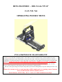
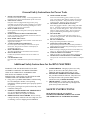
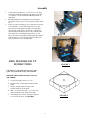
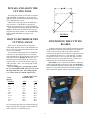
OWNER’S
MANUAL
RING MASTER®
For the DELTA 46-715 14" Wood Lathe
Cat. No. 744
CAUTION - Read important safety instructions AND operation instructions, BEFORE
operating your RING MASTER® (CAT.NO. 744).
Your new RING MASTER® is a quality-built machine, capable of dependable
performance throughout its lifetime. To take full advantage of these capabilities you should
thoroughly understand the proper method and technique of its operation. Therefore, we suggest
you read this manual before operating and that you save it for future reference.
Assembly and Operation
FORM P/N 301128 (6/1/2004)
RING MASTER® - DELTA 46-715 14”
CAT. NO. 744
OPERATING INSTRUCTIONS
PNI’s LIMITED ONE YEAR WARRANTY
PNI is proud of the RING MASTER® it manufactures and warrants it to be free of defects from workmanship and material for a
period of 1 year from the date of original purchase. In the unlikely event that a problem occurs, return the product to our plant
freight prepaid and allowed, so that a determination of the fault can be made. If the fault is determined to be defective materials or
workmanship, a no-charge replacement or repair will be made, at our discretion. The product will be returned to you freight prepaid
and allowed. WARRANTY WILL BE VOID IF REPAIRS ARE MADY BY OTHER THAN FACTORY AUTHORIZED
PERSONNEL AND WILL RELIEVE PNI OF FURTHER LIABILITY UNDER THE GUARANTEE. This warranty does not
cover accidents, abuse or misuse and in no case will PNI be liable for incidental or consequential damages. No other warranty
written or verbal is authorized. This guarantee ends one year after date of original purchase.
PNI reserves the right to change or modify the design and/or specifications of Ring Master at any time without prior notice to any
user.
Returns for warranty service or repair must have a RMA number prior to returning; contact Customer
Service at 800-634-9281. Returns should be sent to:
Porta-Nails, Inc. 4235 US Hwy. 421 N. Currie, NC 28435 Attention Service Dept.
2
General Safety Instructions for Power Tools
1.
2.
3.
4.
5.
6.
7.
8.
9.
10. WEAR PROPER APPAREL
Do not wear loose clothing, gloves, neckties or jewelry
(rings, wrist watches) that could get caught in moving parts.
Wear non slip footwear. Wear protective hair covering to
contain long hair. Roll long sleeves above the elbow.
11. USE SAFETY GOGGLES (Head Protection)
Wear safety goggles at all times. (Must comply with ANSI
Z87.1). Everyday eyeglasses have impact resistant lenses
only. They are NOT safety glasses. Also, use face or dust
mask if a cutting operation is dusty. Wear ear protectors
(plugs or muffs) during extended periods of operation.
12. SECURE WORK
Use a vise or clamps to hold work when practical. It is
safer than using your hands. This will free hands allowing
them to operate the tool.
13. DO NOT OVERREACH
Keep proper footing and balance at all times.
14. MAINTAIN TOOLS WITH CARE
Keep tools sharp and clean for best and safest performance.
Follow instructions for lubricating and changing accessories.
15. DISCONNECT TOOLS
Before servicing or changing accessories such as blades, bits,
cutters, etc., disconnect from electrical and air supplies.
16. AVOID ACCIDENTAL STARTING
Make sure switch is in "OFF" position before plugging it in.
17. NEVER LEAVE TOOL RUNNING UNATTENDED
Turn power off. Do not leave tool until it comes to a complete
stop.
KNOW YOUR POWER TOOL
Read the owner's manual carefully. Learn its applications and
limitations as well as the potential hazards specific to this tool.
GROUND ALL TOOLS
PNI power tools are equipped with an approved 3-prong
grounding type plug to fit the proper grounding type receptacle.
The green conductor in the cord is the grounding wire. Never
connect the green wire to a live terminal.
KEEP GUARDS IN PLACE
Be sure guards are in working order, and in proper adjustment
and alignment.
REMOVE ADJUSTING KEYS AND WRENCHES
Check to see that keys and adjustment wrenches are removed
from tool before turning it on.
KEEP WORK AREA CLEAN
Cluttered areas and benches invite accidents. Floor must not be
slippery due to sawdust.
AVOID DANGEROUS ENVIRONMENT
Do not use power tools in damp or wet locations or expose
them to rain. Keep work area well lit. Provide plenty of
surrounding work space.
KEEP CHILDREN AWAY
All visitors should be kept a safe distance from work area.
DON'T FORCE TOOL
It will do the job better and safer at the rate for which it as
designed.
USE THE RIGHT TOOL
Don't force tool or attachment to do a job it was not designed
for.
Additional Safety Instructions for the RING MASTER®
5.
WARNING: FOR YOUR OWN SAFETY, DO NOT
ATTEMPT TO OPERATE YOUR RING MASTER®
UNTIL IT IS COMPLETELY ASSEMBLED AND
INSTALLED ACCORDING TO THE
INSTRUCTION...AND UNTIL YOU HAVE READ AND
UNDERSTAND THE OWNERS MANUAL.
1. If any part of your RING MASTER® is malfunctioning,
has been damaged or broken, cease operating
immediately until the particular part is properly repaired
or replaced.
2. Never place your fingers in a position where they could
contact the cutting tool.
3. INSPECT YOUR POWER TOOL THOROUGHLY
Set up your RING MASTER® according to
instructions. Make sure all parts are included.
4. KEEP CUTTING TOOLS SHARP - Be sure to keep
cutting tools sharp. Dull tools can cause rough cuts, tool
overheating, excessive chipping and ACCIDENTS.
6.
7.
SAFETY SHIELD - Though you plan to use safety
glasses, do not remove the safety shield. TWO
SHIELDS ARE BETTER THAN ONE, or none.
FOLLOWING OPERATING INSTRUCTIONS All procedures should be followed. They have been
developed to insure safe operation AND complete
satisfaction with your RING MASTER®.
THINK SAFETY - Carefully plan each operation
before turning on tool. Plan each step through to the
point when you turn motor OFF.
SAFETY INSTRUCTIONS
BE SURE TO FOLLOW ALL SAFETY
INSTRUCTIONS BEFORE, DURING AND AFTER
THE OPERATION OF YOUR RING MASTER®!
3
Assembly
1.
2.
3.
Locate index plate (Item A), (1) #10-32 screw 5/8" long,
with washer (Items B) and attach index plate to right end
of "rod base". PLACE SCREW THROUGH SLOT in
index plate.
Find Polycarbonate face shield (Item C) and attach to
swing plate using (3) #8-32 screws and trim washers (Item
D).
Find 3/16" index pin (Item E), move slide plate away from
rear of machine. Loosen index plate lock screw, and
insert index pin through hole in right rear of slide plate
into any hole in index plate. Note, there is a small slot
into which the index plate lock screw fits, slide the index
plate fully to the rear and tighten the lock screw. The
above procedure merely aligns the index plate hole pattern
with the index pin. You will repeat this procedure each
time you loosen or move the index plate.
RING MASTER® SET UP
INSTRUCTIONS
FIGURE 1
CAUTION: Use only knot and crack free "tight
grain" wood. DO NOT cut any other material.
PREPARE THE WOOD FOR MOUNTING ON
THE ARBOR
1. Cut wood in squares not over 11-1/2".
2. Find the center of each square and mark with a
punch.
3. Using a compass, draw the largest circle
possible inside the wood square.
4. Drill a 1/2" hole in the center. A 1/2" hole will
permit mounting on the Arbor of the Lathe.
5. After drilling, saw corners off being careful not
to saw inside the circle. See FIGURE 2.
FIGURE 2
4
MOUNTING THE WOOD ON
THE DELTA 46-715 14" LATHE
Attach the arbor, provided, to the DELTA 46-715
Lathe. Mount the wood on the arbor and place the 15/8" cupped washer on the arbor next to the wood.
Screw on the 1/2" nut and tighten using the 3/4"
wrench provided.
ATTACHING THE 744 RING
MASTER® TO DELTA 46-715 14"
LATHE
1.
2.
3.
4.
5.
6.
Position the 744 RING MASTER® over lathe way
bars as shown.
Place the 744 RING MASTER® Assembly with
Lock Bar (Item H) into middle of way bars as shown.
(Note: Lock Bar is already assembled to 744 RING
MASTER® assembly.)
Place Clamp Bar (Item J) in way bars positioned as
shown.
Insert 1/2" Socket Screw (Item K) through Clamp Bar
(Item J) and into threaded hole in the Lock Bar (Item
H).
Slide the RING MASTER® towards the Head Stock
of the DELTA LATHE until the wood is directly over
the
center of the RING MASTER®.
Tighten the 1/2" Socket Screw with a 3/8" hex
wrench. DONOT OVER TIGHTEN THIS SCREW.
This provides a clamping effect on the way bars to
secure the 744 RING MASTER® to the DELTA
lathe. If in later use the 744 RING MASTER®
assembly seems loose, slightly tighten the 1/2" Socket
Screw. Be sure to lock the head stock in place.
PRIOR TO ANY POWER ON OF YOUR DELTA
LATHE, be sure to refer to your DELTA owners
manual lathe turning chapter for complete
information on the correct operation of the Lathe.
25
24
23
HEAD
STOCK
22
LATHE
WAY BARS
TAIL
STOCK
FIGURE 3
5
INSTALL AND ALIGN THE
CUTTING TOOL
The cutting tool consists of two blades, a left and a
right hand blade. Install blades in proper left and
right hand positions and clamp in place using locking
screws and small hex wrench.
Hold a steel straight edge against the blades and
view from above. If the blades are not properly
aligned, loosen locking screws, realign, and tighten.
Check alignment periodically during operation. BE
SURE no sawdust gets into the blade slot as proper
alignment will not be possible. See "POSITIONING
THE CUTTING BLADES" for proper blade
alignment.
FIGURE 4
HOW TO DETERMINE THE
CUTTING ANGLE
POSITIONING THE CUTTING
BLADES
There are two variables involved in the proper
cutting angle: thickness of the wood and thickness of
the cut. The index plate controls the thickness of the
cut to a 5/16" increment.
To calculate the cutting angle, draw a straight line
vertically on a sheet of paper, place your wood on
edge perpendicular to the line and draw a line on each
side of the wood (See FIGURE 4). Measure 5/16"
along the top line and mark point "B". Draw a line
between points "A" and "B" and measure angle "X"
with a protractor. This is your cutting angle for that
thickness of wood.
If you are cutting 3/4" wood the angle is about
22- 1/2°, and EVERY TIME YOU CUT 3/4" wood
the angle will be the same. The cutting angle for
1/2" wood is about 32 ° and 3/8" about 39 1/2 °.
Wood
Spacing:
Thickness
1/4"
5/16"
3/8"
7/16"
1/2"
9/16"
5/8"
11/16"
3/4"
13/16"
7/8"
Unlock the slide lock, slide assembly forward and position
cutting blades until both left and right blades will engage the
wood. Locate the nearest index stop with the index pin.
Unlock the index plate lock screw and move index plate to the
rear, and tighten the lock screw. Lock slide lock. To adjust
swing plate reference #34, loosen front slide plate lock bolt,
reference #28, loosen swing plate lock bolt, reference #29.
Adjust swing plate to desired angle and tighten.
BY HAND, rotate wood one full revolution to insure that
both left and right blades will engage wood. See FIGURE 5.
If you find that the left blade will not engage the wood, unlock
slide lock, remove index pin and slide forward to engage the
NEXT index hole. Replace index pin and lock slide lock.
Cutting Angle To Use
With Index Plate
5/16"
51.1°
44.8°
39.6°
35.3°
31.8°
28.9°
26.4°
24.3°
22.5°
20.9°
19.5°
3/8"
56.3°
50.2°
45°
40.6°
36.9°
33.7°
30.9°
28.6°
26.5°
24.8°
23.2°
Once the cutting angle has been calculated, align the
degree setting on the swing plate with the scribe line
on the slide plate. Lock the swing lock.
6
RING MASTER® OPERATING
INSTRUCTIONS
Now that you have set up the RING MASTER® to
properly cut your rings, you are ready to begin. Remember
to observe proper safety precautions when operating the
RING MASTER®.
Start motor, turn lead screw clockwise and advance left
blade very slowly into the wood. (NOTE: When cutting,
always advance the blade slowly. Should you attempt to
cut too rapidly, you may experience chattering, vibration,
checking of your work piece, or misalignment of the cutting
blade.) Since each revolution yields 1/13" of movement,
advance slowly for about six turns in 3/4" wood or until
halfway through wood. Then reverse the turn and start to
cut from the right side. Move slowly until you notice a
change in the sound of the cutting. As the ring starts to fall
off to the right, STOP the motor and clear the ring from the
machine. You will have to unlock the slide lock to remove
the ring.
You'll note the outer shape of this first ring is octagonal
and will not mate with any other ring, lay this ring aside for
OTHER use.
To cut the next ring adjust the blades to clear on both
sides of the ring and slide forward for the next cut. Replace
the index pin and lock the slide. NEVER ATTEMPT TO
CUT A RING WITHOUT FIRST LOCKING THE SLIDE
LOCK. Repeat the process explained above to cut your
next ring.
After cutting two rings, stack the small ring on top of
the larger as shown in FIGURE 6. This will indicate if the
cutting angle is correct. (NOTE: Having calculated and set
the cutting angle on the degree scale is no guarantee that the
rings will be cut with a good alignment. A good match of
the rings can now be accomplished with minor adjustment
of the cutting angle. If the top ring is larger at its base than
the bottom ring, the angle must be decreased slightly. If the
top ring is smaller at its base than the bottom ring, the angle
must be increased slightly. If the rings do no match closely,
adjust the angle and cut TWO more rings to check for
acceptable alignment.
FIGURE 5
CUTTING SPEED
You may vary the R.P.M. depending on the diameter
of the ring. Cut the largest 10-11" dia. rings at slow (700
R.P.M.) and raise the speed NOT TO EXCEED "C" (900
R.P.M.) for the smallest rings.
Good Alignment
Increase Angle For Good Alignment
Decrease Angle For Good Alignment
FIGURE 6
7
CHANGING THE CUTTING
ANGLE TO 90 DEGREES
WORKING WITH
THE RINGS
After you have cut a number of angle rings, you will want
to cut some straight or 90 degree rings whose outside diameter
will match the angle rings already cut. Leave the last of an
angle cut piece on the spindle with the lock nut in place. Set the
wing plate to 90 degrees and lock. Remove the index pin, slide
the blade forward until the left blade just touches the left
portion of the wood. See FIGURE 7. When contact is made
with the wood, lock the slide lock.
Unlock the index plate and slide forward until the index pin
will engage the nearest hole. Lock the index plate screw.
Unlock slide lock and pull cutting assembly to the rear.
Remove angle cut wood and replace with a new piece of wood.
You are now ready to continue with cutting straight rings.
After you have cut a supply of angle and straight
rings, the fun begins. FIGURE 8 illustrates the basic
ways in which you can put the rings together to form
different shapes. What you make, how large you make it,
what wood or combinations of wood you use, and the
finish you apply is all up to you. Now that you have cut
rings around wood, you can create any hollow cylindrical
wooded project.
REMEMBER, RING MASTER® can easily
DUPLICATE any project you make.
A. Two identical rings for sharp outside curve or;
B. Two identical rings for sharp inside curve.
C. Two identical angle rings used with mating straight
ring to yield a soft outside curve or;
D. Two identical angle rings used with mating straight
ring to yield a soft inside curve.
E. A number of straight rings stacked.
F. Mating angle rings, possibly all cut from the same
piece of wood.
FIGURE 7
FIGURE 8
CUTTING A
STRAIGHT RING
GLUING YOUR
PROJECT
The procedure to cut a straight ring is the same as cutting
an angle ring.
Slide the cutting blades to the wood and insure that both
blades will fully engage wood. Insert index pin in nearest hole
and lock slide. BY HAND, rotate wood one full revolution to
insure blades will engage wood on both sides for the full circle.
Start motor. Cut first from the right and then the left. As the
cutting sound changes and the ring starts to move, stop the
motor and clear the ring from the machine. Cut a second ring in
the same manner. (The first ring will have and octagonal outer
shape and can be used for projects such as clock faces, etc.)
If the above instructions were followed correctly, the
second straight ring will match the outside diameter of an
angle ring cut earlier. If it does not match the outside
diameter of and angle ring, repeat above instruction but be
careful to just touch the blade to remnant of angle wood.
Once you have decided on the shape of your project, it
is time to glue it together. Use any furniture glue that is
water soluble. Tight Bond Glue by Franklin is good. It is
helpful to use a gluing jig like the one shown in FIGURE
9. It is actually a 3/8" threaded rod and a wing nut. Most
projects will be glued upside down to utilize the 1/2"
spindle hole found in the center ring.
Start with the ring that is on the open end of the
project. Lay it down flat on a piece of secured sandpaper
on a flat surface. Move the ring in a circular motion on
both sides of the ring to remove any splintered wood fibers
to ensure the glued joints fit properly. Next, lay the ring
on the gluing jig and apply glue to the top surface of the
ring. Place the next ring on top and glue its top surface.
Continue until the last piece with the 1/2" hole is in place.
The last piece acts as a part of the clamp. Place a washer
and the wing nut on the threaded rod and tighten until
8
some glue is squeezed out from between the rings. Use a
damp cloth to remove any excess glue. Then loosen the
clamp, check to see that the rings are still aligned as you
wish, and tighten the clamp firmly.
See "RECOMMENDED ACCESSORIES (Options)" for
information on ordering a GLUE/CLAMPING FIXTURE.
FINISHING YOUR PROJECT
Once your project has been glued, and dried overnight,
you may return your project back to the DELTA Lathe for
sanding, detailing and finishing. Simply fit the 1/2" hole in
the bottom of your project back on the arbor and tighten
1/2" nut.
Your STEADY REST and LATHE KNIVES can be
used in the usual way for detailing. However, only sand
paper will yield a nice finish. Use you choice of finish, for
a fine project.
Remember, by using the RING MASTER®, you can
easily duplicate any project.
HAVE FUN!
FIGURE 9
RECOMMENDED ACCESSORIES (Options)
1.
2.
3.
4.
5.
6.
7.
CATALOG NUMBERS
Replacement Cutter Blade (Double End) ............................................. 70140
Replacement Cutter Set (Double End - High Speed) ............................ 70141
1/2" Diameter Drill With 1/4" Shaft ..................................................... 70130
Glue/Clamping Fixture ..........................................................…........... 70100
1/2" Plug Cutter .........................................…......................….......…. 70160
Cutter Pre-Set Gauge .............................................................….......... 70138
Drum Sander 2 1/2" x 3" ........................................................….......... 70166
9
70166
70138
70140, 70141
70130
ADJUSTMENTS
MAINTENANCE
Keep your RING MASTER® clean. If compressed
air is available, blow each part clean after use. Keeping
the lead screw clean of saw dust is very important.
End play may occur in the lead screw. If it occurs,
correct the situation as follows:
LEAD SCREW: Loosen set screw on handle
(Reference #31) and press tool holder (Reference #23)
toward handle (Reference #32). As you press handle
toward tool holder tighten set screw.
TROUBLE SHOOTING
WARNING: For your safety, turn switch "off" and always remove plug from power source before
trouble shooting.
TROUBLE
PROBABLE CAUSE
REMEDY
Chattering
Cutting Feed too Fast
Dull Cutter
Blade Misalignment
Advance Cutter Slowly
Sharpen or Change Cutter
Realign Cutters
Excessive Chipping
Feed too Fast
Slow Down
Cutter Darkens
Cutter Dull
Sharpen or Replace Cutter
Excessive Vibration
Base Not Clamped
Clamp or Bolt Base Down
Feed Screw Binding
Dirt or Dust Build-up
Dis-assemble - Clean
Use Multipurpose Grease
10
6
15
14
5
37
35
18
10
33
18
17
2
16
36
3
4
27
3
29
20
7
13
28
9
12
25
34
32
19
8
11
30
24
19
1
21
26
1
23
22
11
31
Item No.
Part No.
Qt
Part Description
1
2
3
4
5
6
7
8
9
10
11
12
13
14
15
16
17
18
19
20
21
22
23
24
25
26
27
28
29
30
31
32
33
34
35
36
37
301070
301443
301422
301423
301427
301442
301444
301202
301203
301204
301206
301207
301404
301440
301421
301701
301702
301784
301870
301103
301975
301956
301121
301964
301962
200724
301430
301432
301434
301302
301970
301979
301127
70140
301403
301436
301435
3
1
5
1
1
1
1
2
1
1
1
1
1
1
1
2
1
3
2
1
1
1
1
1
2
2
2
4
1
2
1
1
1
2
1
3
3
Nyloc Hex Nut ¼-20
Swing Frame Lock Screw
Socket Cap Screw 10-32
Washer SAE #10
Washer USS 3/8
Knob
Washer 5/8 ID 1” OD
Slide Lock
Rod Base
Back Rod Clamp
Front Rod Base
Front Rod Clamp
Index Plate
Slide Plate
Index Pin
Guide Rod
Hex Head Screw 3/8-16
Socket Flat Head Screw ¼-20
Socket Flat Head Screw Special 3/8-16
Crank Handle
Base Bar
Clamp Bar
Lock Bar
Slide Rod Base
Socket Flat Head Screw – Special Clamping
Socket Flat Head Screw 3/8-16
Thrust Washer
“E” Retaining Ring
Socket Set Screw 10-32
Slide Rod
Tool Holder
Lead Screw
Swing Frame
Cutter Blade
Safety Shield
Finish Washer
Philips Head Screw 8-32
12
NOTES
PO Box 1257, Wilmington, NC 28402
910-762-6334 * 800-634-9281 * FAX: 910-763-8650
www.ringmastertool.com
[email protected]
13