1
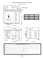
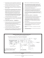
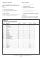
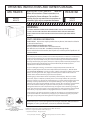
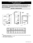
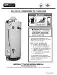
OPERATING INSTRUCTIONS AND OWNER’S MANUAL
MR. HEATER
HEATSTAR
M ODEL
M ODEL
MHU 45
MHU 75
READ INSTRUCTIONS CAREFULLY:
Read and
follow all instructions. Place instructions in a
safe place for future reference. Do not allow
anyone who has not read these instructions to
assemble, light, adjust or operate the heater.
HSU 45
HSU 75
COMPACT UNIT HEATER
WARNING:
Improper installation, adjustment, alteration, service or maintenance can
cause injury or property damage. Refer to this manual. For assistance or additional
information consult a qualified installer, service agency or the gas supplier.
— WHAT TO DO IF YOU SMELL GAS
• Open Windows
•
DO NOT try to light any appliance.
•
DO NOT use electrical switches.
•
DO NOT use any telephone in your house. Immediately call your local gas supplier from a
neighbor’s telephone. Follow the gas supplier’s instructions.
•
Do not touch any electrical switch; do not use any phone in your building.
•
Installation and service must be performed by a qualified installer, service agency or the gas
supplier.
•
If you cannot reach your gas supplier, call the Fire Department.
FOR YOUR SAFETY:
Do not store or use gasoline or other flammable vapors and liquids in the vicinity of
this or any other appliance.
WARNING: If the information in these instructions are not followed exactly, a fire or
explosion may result causing property damage, personal injury or loss of life.
ENERCO GROUP, INC., 4560 W. 160TH ST., CLEVELAND, OHIO 44135 • 216-916-3000
03/05 Revision L1 #60016
WARNING:
WARNING:
YOUR SAFETY IS IMPORTANT TO YOU AND TO OTHERS,
SO PLEASE READ THESE INSTRUCTIONS BEFORE YOU
OPERATE THIS HEATER.
FIRE, BURN, INHALATION, AND EXPLOSION HAZARD.
KEEP SOLID COMBUSTIBLES, SUCH AS BUILDING
MATERIALS, PAPER OR CARDBOARD, A SAFE DISTANCE AWAY FROM THE HEATER AS RECOMMENDED
BY THE INSTRUCTIONS NEVER USE THE HEATER IN
SPACES WHICH DO OR MAY CONTAIN VOLATILE OR
AIRBORNE COMBUSTIBLES, OR PRODUCTS SUCH AS
GASOLINE, SOLVENTS, PAINT THINNER, DUST PARTICLES OR UNKNOWN CHEMICALS.
GENERAL HAZARD WARNING:
FAILURE TO COMPLY WITH THE PRECAUTIONS AND
INSTRUCTIONS PROVIDED WITH THIS HEATER, CAN
RESULT IN DEATH, SERIOUS BODILY INJURY AND
PROPERTY LOSS OR DAMAGE FROM HAZARDS OF FIRE,
EXPLOSION, BURN, ASPHYXIATION, CARBON MONOXIDE POISONING, AND/OR ELECTRICAL SHOCK.
ONLY PERSONS WHO CAN UNDERSTAND AND FOLLOW
THE INSTRUCTIONS SHOULD USE OR SERVICE THIS
HEATER.
IF YOU NEED ASSISTANCE OR HEATER INFORMATION
SUCH AS AN INSTRUCTIONS MANUAL, LABELS, ETC.
CONTACT THE MANUFACTURER.
WARNING:
The State of California requires the following warning:
COMBUSTION BY-PRODUCTS PRODUCED WHEN
USING THIS PRODUCT CONTAIN CARBON MONOXIDE,
A CHEMICAL KNOWN TO THE STATE OF CALIFORNIA
TO CAUSE CANCER AND BIRTH DEFECTS (OR OTHER
REPRODUCTIVE HARM).
CONTENTS
UNIT DIMENSIONS ................................................................. 3
SHIPPING ................................................................................ 4
REQUIREMENTS ...................................................................... 4
UNIT HEATER INSTALLATION .................................................. 5
COMBUSTION & VENTILATION AIR ........................................ 5
VENTING ................................................................................. 5
ELECTRICAL CONNECTIONS .................................................... 8
GAS CONNECTION ................................................................. 8
LEAK CHECK ........................................................................... 9
START-UP OPERATION ............................................................. 9
HEATING SEQUENCE OF OPERATION ..................................... 10
IGNITION CONTROL LED ........................................................ 11
ADJUSTMENTS ....................................................................... 11
SERVICE ................................................................................. 12
WIRING DIAGRAM ................................................................. 13
PARTS LIST ............................................................................. 14
WARRANTY ........................................................................... 16
Enerco | Compact Unit Heater
2
Operating Instructions and Owner’s Manual
MHU45/MHU75 AND HSU45/HSU75 UNIT DIMENSIONS
(N-NATURAL GAS, P-PROPANE)
HANGING
BRACKETS
MOUNTING SLOTS (Typical)
5/16 x 3 Inches (8 x 76 mm)
AIR
FLOW
DIMENSION
45
75
A
12 (305)
17 (432)
B
5-1/2 (140)
6-1/2 (165)
C
4-1/4 (108)
6-3/4 (171)
HEAT EXCHANGER
(ALUMINIZED STEEL)
TOP VIEW
ELECTRICAL
INLETS
DIRECT
DRIVE FAN
FLUE
OUTLET
HANGING
BRACKETS (2)
GAS
INLET
ADJUSTABLE
LOUVERS
SERVICE
ACCESS PANEL
SIDE VIEW
BACK VIEW
START–UP AND PERFORMANCE CHECK LIST
Job Name: _________________________________________
Job No.: ______________________________________
Date: ______________________________________
Job Location: _______________________________________
City: _________________________________________
State/Province: ______________________________
Installer: __________________________________________
City: _________________________________________
State/Province: ______________________________
Unit Model No.: ____________________________________
Serial No.: ____________________________________
Service Technician: ___________________________
Electrical Connections Tight? ______________________________________________ Flue Connections Tight? _________________________________________________
Supply Voltage __________________________________________________________ Fan Timer Operation Checked? ____________________________________________
Gas Piping Connections Tight & Leak-Tested? _________________________________ THERMOSTAT
Motor Amps ____________________________________________________________ Calibrated? ____________________________________________________________
Furnace Btu Input ________________________________________________________ Heat Anticipator Properly Set?
Line Pressure ____________________________________________________________ Level? _________________________________________________________________
Manifold Pressure w.c. ____________________________________________________
Enerco | Compact Unit Heater
3
Operating Instructions and Owner’s Manual
SHIPPING
TABLE 1
UNIT CLEARANCES
The heater is completely assembled. Installation instructions, two
mounting brackets (shipped loose), and a flue transition are
included. Check the unit for shipping damage. The receiving
party should contact the last carrier immediately if any shipping
damage is found.
Top
REQUIREMENTS – CSA IN THE USA
Installation of gas unit heaters must conform with local building
codes or, in the absence of local codes, with the current National
Fuel Gas Code ANSI Z223.1.
mm
in
1
25
1
mm
25
Bottom
in
mm
in
mm
0
18
456
0
Rear
Access Panel
in
mm
18
457
Single Wall Vent*
in
mm
6
152
*Except for listed clearance thimbles.
Installation in aircraft hangers must be in accordance with the
current Standard for Aircraft Hangers ANSI/NFPA No. 409.
REQUIREMENTS – CSA IN CANADA
Installation in parking structures must be in accordance with the
current Standard for Parking Structures ANSI/NFPA No. 88A.
The instructions are intended only as a general guide and do not
supersede local codes in any way. Authorities having jurisdiction
should be consulted before installation. The installation must
conform with local building codes or in the absence of local
codes, with the current CSA B149.1, Natural Gas and Propane
Installation Code. All electrical wiring and grounding for the unit
must also comply with the Canadian Electrical Code CSA C22.1,
current edition.
Installation in repair garages must be in accordance with the
current Standard for Repair Garages ANSI/NFPA No. 88B.
These units are approved for residential applications. For
installation in a residential garage these units must be installed
so that burners and ignition source are located no less than 18"
(457mm) above floor. Heater must be located or protected to
avoid physical damage by vehicles. Refer to the National Fuel Gas
Code, ANSI Z223.1, current edition.
These unit heaters are CSA International. certified for the
clearances to combustible material listed on the rating plate and
table 1. Adequate clearance around air openings into the
combustion chamber, clearances from combustible material, and
provisions for accessibility and for combustion and ventilation air
supply. Provision shall be made for service accessibility to the
heater. Note that fire protection clearances may be exceeded to
provide additional space for service and accessibility.
Authorities having jurisdiction should be consulted before NFPA
installation. Air for combustion and ventilation must conform to
the methods outlined in ANSI Z223.1, section 5.3, Air for
Combustion and Ventilation, or applicable provisions of local
building codes. The National Fuel Gas Code is available from:
American National Standard Institute Inc.
11 West 42nd Street
New York, NY 10036
GARAGE INSTALLATIONS:
Installation in parking structures must be in accordance with the
current Standard for Parking Structures ANSI/NFPA No. 88A.
These units are CSA International design certified. These unit
heaters are certified for installation to combustible material as
listed in table 1 and on unit rating plate. Accessibility and service
clearances must be observed in addition to fire protection
clearances.
Installation in repair garages must be in accordance with the
current Standard for Repair Garages ANSI/NFPA No. 88B.
All electrical wiring and ground for unit must be in accordance
with the regulations of the current National Electric Code ANSI/
No. 70.
1.
In a storage area, clearance from heaters to combustible
materials must be such that the material shall not attain a
temperature above 160°F by continuous operation of the
unit.
2.
Eight foot minimum clearance from the floor to the bottom
of the heater must be maintained. Refer to the CSA B149.1,
Natural Gas and Propane Installation Code
The National Electric Code is available from:
National Fire Protection Association
1 Batterymarch Park
PO Box 9101
Quincy, MA 02269-9101
Enerco | Compact Unit Heater
Sides
in
AIRCRAFT HANGER:
Installation of gas unit heaters must conform with local building
codes or, in the absence of local codes, with the current National
Fuel Gas Code ANSI Z223.1.
4
1.
In an area where aircraft are housed or serviced, 10'
minimum clearance from highest surface of aircraft to
bottom of the heater must be maintained.
2.
In other areas, 8' minimum clearance from the floor to
bottom of heater must be maintained.
3.
Heaters should be located so as to be protected from
damage from aircraft or other appliances needed for
servicing of aircraft. Refer to requirements of the enforcing
authorities.
Operating Instructions and Owner’s Manual
These units are approved for residential applications. For installation in a
residential garage, these units must be installed so that burners and
ignition source are located no less than 18” (457mm) above floor. Heater
must be located or protected to avoid physical damage by vehicles.
Refer to CSA B149.1, Natural Gas and Propane Installation Code current
edition.
COMBUSTION AND VENTILATION AIR
Adequate facilities for supplying air for combustion and
ventilation must be provided in accordance with the latest edition
of section 5.3, Air for Combustion and Ventilation, of the
National Fuel Gas Code, ANSI Z223.1, in the U.S.A., CSA B149.1
Natural Gas and Propane Installation Code in Canada,
or applicable provisions of local building codes.
In a confined area, the heater must be installed in accordance with the
CSA B149.1, Natural Gas and Propane Installation Code. Be sure to check
with local codes and ordinances for additional requirements.
All gas fired appliances require air to be used for the combustion
process. In many buildings today, there is a negative indoor air
pressure caused by exhaust fans, etc. If sufficient quantities of
combustion air are not available, the heater or another
appliance will operate in an inefficient manner, resulting in
incomplete combustion which can result in the production of
excessive carbon monoxide.
UNIT HEATER INSTALLATION
The installation shall conform with local building codes or, in the absence
of local codes, with the National Fuel Gas Code, ANSI Z223.1 /
NFPA 54 or the CSA B 149.1, Natural Gas and Propane
Installation Code.
The appliance and venting system is to be inspected once a year
by a qualified service agency.
CAUTION Insufficient combustion air can cause headaches,
nausea, dizziness, asphyxiation or death.
Unit is shipped ready for installation. Unit may be installed
as shown in figure 1 or inverted 180 o depending on desired location
as governed by clearances, vent connection, air direction, gas
supply, electrical supply and service accessibility.
1.
If installing unit in an inverted position: Remove and retain screws
o
securing door and rotate door 180 . Secure with retained screws.
Rotate louvers directing airflow as desired.
2.
Choose location for mounting brackets.
3.
Remove and retain three screws along top edge (bottom edge
when inverted) of front of unit.
4.
5.
If indoor air is to be used for combustion, it must be free of the
following substances or the life of the heat exchanger will be
adversely affected: chlorine, carbon tetrachloride, cleaning solvent,
halogen refrigerants, acids, cements and glues, printing inks,
fluorides, paint removers, varnishes, or any other corrosives.
VENTING
A – GENERAL RECOMMENDATIONS AND
REQUIREMENTS
NOTE: The vent is a passageway, vertical or nearly so, used to
convey flue gases from an appliance, or its vent connector, to the
outside atmosphere. The vent connector is the pipe or duct that
connects a fuel-gas burning appliance to a vent or chimney.
Align screw holes on mounting bracket with holes along top edge
(either upright or inverted) of unit. Secure one mounting bracket
to front of unit with retained screws. Secure other mounting
bracket to back of unit with screws provided in bag assembly
containing flue transition.
Unit heaters must be vented in compliance with all local codes or
requirements of the local utility, the current standards of the
(American) National Fuel Gas Code, ANSI Z223.1 or (Canada) CSA
B149.1 Natural Gas and Propane Installation Code, and the
following instructions.
To support unit, secure mounting bracket to ceiling joist or truss.
Unit may also hang on rods as shown in figure 1 .
A metal stamped/extruded transition is supplied with this certified
unit. It must not be modified or altered and must be installed on
the outlet of the induced draft blower assembly prior to the
installation of the vent or vent connector. Failure to comply with
this requirement will void the certification of the unit by the
approval agencies. All joints shall be secured with at least two
corrosion resistant screws. All joints must be checked for gas
tightness after installation.
INSTALL UNIT HEATER
SUPPORT
RODS
MOUNTING
BRACKETS (2)
TABLE 2
MAXIMUM VENT LENGTHS
HORIZONTAL VENTS
FIGURE 1
No. of
Elbows
ft
m
1
25
7.6
2
20
6.1
3
15
4.6
4
10
3.0
5
5
1.5
Maximum length of vent connector not to exceed 30 ft. (9.1m).
Enerco | Compact Unit Heater
5
Operating Instructions and Owner’s Manual
B – VERTICAL VENTS USING METAL VENT PIPE
– COMMERCIAL AND RESIDENTIAL
INSTALLATIONS
C – HORIZONTAL VENTING – GENERAL
Common venting is not allowed when horizontally venting the unit
heater.
The minimum horizontal vent length is three feet (914mm).
MHU/HSU compact unit heaters are listed as Category I
appliances for vertical vent installations.
1.
2.
3.
4.
5.
6.
7.
MHU/HSU unit heaters are to be used with NFPA- or ANSIapproved chimneys, U.L. listed type B-1 gas vents, single wall
metal pipe, or listed chimney lining system for gas venting
where applicable, as well as the modifications and limitations
listed in figure 2 . Seal single wall vent material according to
the section A - General Recommendations and Requirements.
1.
If possible, do not terminate the horizontal vent through a wall that
is exposed to prevailing wind. Exposure to excessive winds can
affect unit performance. If such a termination is necessary, use a
wind block to protect the vent termination from direct wind.
2.
Vent termination must be free from obstructions and at least
12" (306mm) above grade level and maximum snow height.
The vent connector shall be 3" (76 mm) diameter on 45 unit
and 4” (100mm) diameter for the 75 unit. In all cases, a
flue transition piece (supplied) is required to fit over the
outlet of the induced draft assembly on the appliance.
VENT TERMINATION ON SINGLE WALL VENT
SINGLE WALL TERMINATION
ROOF FLASHING
Keep the vent connector runs as short as possible with a
minimum number of elbows. Refer to the (American)
National Fuel Gas Code ANSI Z223.1 or (Canada) CSA B149.1
Natural Gas and Propane Installation Code for maximum vent
and vent connector lengths. Horizontal run of the vent
connector from the induced draft blower to the chimney/vent
cannot exceed the values in table 2 .
ROOF PITCHED
FROM 0” TO 45”
When the length of a single wall vent, including elbows,
exceeds 5 feet (1.5m), the vent shall be insulated along its
entire length with a minimum of 1/2" thick foil faced
fiberglass 1-1/2# density insulation. If a single wall vent is
used in an unheated area it shall be insulated. Failure to do
so will result in condensation of flue gases.
DOUBLE WALL (TYPE B-1) TERMINATION
ROOF FLASHING
The unit may be vented vertically as a single appliance or as a
common vent with other gas-fired appliances. In common
venting situations, vent connectors for other appliances must
maintain a 4" (100mm) vertical separation between the vent
connectors. Refer to common venting tables in the(American)
National Fuel Gas Code ANSI Z223.1 or (Canada) CSA B149.1
Natural Gas and Propane Installation Code for proper vent
size.
ROOF PITCHED
FROM 0” TO 45”
12” MAX
FIGURE 2
The vent connector shall be supported without any dips or
sags. Vertical vents shall be supported in accordance with
their listing and manufacturers’ instructions. All horizontal
vent connector runs shall have a slope up to the vertical
vent of at least 1/4" per foot (1mm per 50mm).
All vertical type B-1 vents, single wall vents, or listed chimney
lining system must be terminated with a listed ventcap or
listed roof assembly.
9.
The vent must extend at least 3' (1m) above the highest point
where it passes through a roof of a building and at least 2’
(0.6m) higher than any part of a building within a horizontal
distance of 10' (3.05m) unless otherwise specified by the
(American) National Fuel Gas Code, ANSI Z223.1 or (Canada)
CSA B149.1 Natural Gas and Propane Installation Code.
The vent must extend at least 5' (1.6m) above the highest
connected equipment flue collar.
Enerco | Compact Unit Heater
CLEARANCE TO BE AS
SPECIFIED ON TYPE “B”
VENT PIPE
SEAL JOINT BETWEEN SINGLE WALL VENT
AND “B”VENT AND THE ANNULAR SPACE OF THE “B” VENT
Clearance to combustible material is 6" (152mm) for single
wall vent material except where a listed clearance thimble
is used. Clearance to combustible material for type B-1 vent or
factory-built chimney is per manufacturer’s instructions.
8.
2” CLEARANCE
THIMBLE
SHALL NOT BE A
CONCEALED SPACE
6
3.
Do not terminate vent directly below roof eaves or above a
walkway, or any other area where condensate dripping may
be troublesome and may cause some staining. Avoid windows
where steam may cause fogging or ice buildup.
4.
When horizontally vented, minimum clearance for termination
from any door, window, gravity air inlet, gas or electric meter,
regulators, and relief equipment is 4 ft. (1.2m) for U.S.
installations. Refer to NFPA 54/ANSI Z223.1 in the U.S.A. and
CSA B149.1 Natural Gas and Propane Installation Code
in Canada or with authorities having local jurisdiction. In
Canada, vent termination must have a minimum 6 ft.
(1.8mm) horizontal clearance from gas and electric meters
and relief devices as specified in the CSA B149.1, Natural
Gas and Propane Installation Code.
Operating Instructions and Owner’s Manual
5.
Vent termination must be a minimum of 4' (1.2m) below or 4’
(1.2m) horizontally from any soffit vent or under-eave vent.
6.
Vent must be a minimum of 6' from an inside corner formed
by two exterior walls. If possible, leave a 10' clearance.
7.
Vent termination must be a minimum of 10' (3m) from any
forced air inlet (includes fresh air inlet for other appliances,
such as a dryer).
8.
When termination is routed through an exterior combustible
wall the vent must be supported using a listed clearance
thimble. Where local authorities permit, a single section of
type B-1 vent pipe may be used as an alternative to the
thimble. When using a type B-1 vent termination use the
clearances specified by the vent manufacturer. Seal the
connection between the single wall and double wall pipes and
the annular space of the double wall pipe as shown in figure
2. Inside edge of vent termination tee must be at least 12
inches from outside wall as shown in figure 3 .
9.
3.
Refer to table 2 for maximum vent connector lengths.
4.
Select a wall termination point that will maintain ¼” rise per
foot slope of horizontal run of vent pipe. The vent may be
single wall material minimum 26 GSG (0.46mm) galvanized
steel or equivalent grade stainless steel. Seal single wall vent
material according to the section A - General
Recommendations and Requirements.
5.
For upward sloped vent a condensate tee and drain must be
installed within the first 5’ (1.5m) from the unit heater to
protect the appliance. If a flexible condensate drain line is
used, the drain line must include a loop entering the structure.
If the unit is shut down for an extended period of time and
will be exposed to sub-freezing temperatures, the condensate
may freeze.
E – HORIZONTAL VENTING – RESIDENTIAL
1.
For horizontal residential installations these units are certified
as Category I appliances. The vent may be single wall
material minimum 25 GSG (0.46mm) galvanized steel or
equivalent grade stainless steel. Venting A - General
Recommendations and Requirements and C - Horizontal
Venting General and E - Horizontal Venting - Residential.
Refer to figure 6 .
2.
The vent pipe diameter for horizontal residential installations
shall be 4" (101mm) on both 45 and 75 units. A standard vent
transition is required at unit in addition to the transition
supplied with the unit.
3.
The maximum vent length is 5’ (1.5m) plus one 90-degree
elbow.
4.
The vent must maintain a ¼” rise per foot of slope upwards
toward the termination.
For horizontal venting, the vent pipe shall be supported with
hangers no more than 3ft. (1m) apart to prevent movement
after installation.
D – HORIZONTAL VENTING – COMMERCIAL
1.
Horizontal commercial installations are for buildings which are
not attached to living spaces. The vent may be single wall
vent material installed according to the sections
Venting A - General Recommendations and Requirements
and C - Horizontal Venting General and
D - Horizontal Venting - Commercial. Refer to figure 3.
2.
The vent pipe diameter for horizontal commercial
installations shall be 4" (101mm) on the 45 and 75units. In all
cases a flue transition piece (supplied) is required to fit over
the outlet of the induced draft assembly on the appliance.
CONDENSATE DRAIN THROUGH TEE PIPE AND DRAIN LOOP
UPWARD SLOPE ON HORIZONTAL VENT-COMMERCIAL INSTALLATION
MAY BE SINGLE WALL (26 GSG) GALV. OR EQUIV. STAINLESS STEEL SEALED ACCORDING TO
THESE INSTALLATION INSTRUCITONS. SLOPE: + 1/4 INCH FOR 1 FOOT RUN MINUMUM.
12 INCHES MIN.
(30.5 CM)
FLUE TRANSITION
(PROVIDED)
VENT TERMINATION
CAP
LISTED THIMBLE
THROUGH COMBUSTIBLE
WALL
INDUCED DRAFT BLOWER
NOTE - MINIMUM HORIZONTAL LENGHT 3 FT. (914MM),
NOT INCLUDING CAP FOR TERMINATION. REFER TO
TABLE 2 FOR MAXIMUM LENGTH AND NUMBER OF
ELBOWS.
12” (30.5 CM)
MINIMUM ABOVE ALL
HIGHEST SNOWFALL
DRAIN LOOP WITH WATER
TRAP (TO CONDENSATE DRAIN)
COMMON VENTING NOT ALLOWED WHEN HORIZONTALLY VENTING THE UNIT HEATER
FIGURE 3
Enerco | Compact Unit Heater
7
Operating Instructions and Owner’s Manual
INDUCED DRAFT BLOWER
HORIZONTAL VENTING - RESIDENTIAL INSTALLATION
UPWARD SLOPE
12 INCHES
MIN. (30.5CM)
FLUE TRANSITION
(PROVIDED)
VENT TERMINATION CAP
LISTED THIMBLE THROUGH
COMBUSTION WALL
MAY BE SINGLE WALL (26 GSG) GALV. OR EQUIV. STAINLESS
STEEL SEALED ACCORDING TO THESE INSTALLATION
INSTRUCTIONS OR A SINGLE SECTION OF TYPE B-1 VENT.
SLOPED: + 1/4 INCH FOR 1 FOOT RUN MINIMUM.
NOTE - MINIMUM HORIZONTAL LENGTH 3FT. (914MM), NOT
INCLUDING CAP FOR TERMINATION.
MAXIMUM HORIZONTAL LENGHT 5FT. (1.5M) PLUS ONE 90DEGREE ELBOW.
COMMON VENTING NOT ALLOWED WHEN HORIZONTALLY VENTING THE UNIT HEATER.
FIGURE 6
F – VENTING USING A MASONRY CHIMNEY
The following additional requirements apply when a lined masonry
chimney is being used to vent the compact unit heater.
1.
Masonry chimneys used to vent Category I units heaters
must be either tile-lined or lined with a listed metal lining
system or dedicated gas vent. Unlined masonry chimneys are
prohibited. A category I appliance must never be connected
to a chimney that is servicing a solid fuel appliance. If a
fireplace chimney flue is used to vent this appliance, the
fireplace opening must be permanently sealed.
2.
A fan assisted unit heater may be commonly vented into an
existing lined masonry chimney provided:
•
•
A type B-1 vent or masonry chimney liner shall terminate
above the roof surface with a listed cap or a listed roof
assembly in accordance with the terms of their respective
listings and the vent manufacturer’s instructions.
Do not install a manual damper, barometric draft regulator,
or flue restrictor between the unit heater and the chimney.
5.
If type B-1 double-wall vent is used inside a chimney, no
other appliance can be vented into the chimney. Outer wall
of type B-1 vent pipe must not be exposed to flue products.
6.
Insulation for the flexible vent pipe must be an encapsulated
fiberglass sleeve recommended by the flexible vent pipe
manufacturer.
Enerco | Compact Unit Heater
8.
If type B-1 vent or an insulated flexible vent pipe cannot be
used as liners, the chimney must be rebuilt to accommodate
one of these methods or some alternate approved method
must be found to vent the appliance. When inspection reveals
that an existing chimney is not safe for the intended purpose,
it shall be rebuilt to conform to nationally recognized
standards, lined or relined with suitable materials or replaced
with a gas vent or chimney suitable for venting unit heaters.
The chimney passageway must be checked periodically to
ensure that it is clear and free of obstructions.
In the event that an existing unit heater is removed from a venting
system commonly run with separate gas appliances, the venting
system is likely to be too large to properly vent there maining
attached appliances. The following test should be conducted while
each appliance is in operation and the other appliances are not in
operation, yet remain connected to the common venting system.
If the venting system has been installed improperly, the system
must be corrected.
The vent connector and chimney are sized in accordance
with venting tables in the (American) National Fuel Gas
Code ANSI Z223.1 or (Canada) CSA B149.1 Natural Gas
and Propane Installation Code.
4.
The space between liner and chimney wall should NOT be
insulated with puffed mica or any other loose granular
insulating material.
G – REMOVAL OF UNIT FROM COMMON VENT
The chimney is currently serving at least one draft-hood
equipped appliance.
IMPORTANT Single appliance venting of a fan assisted unit heater
into a tile lined masonry chimney (interior or outside wall) is
prohibited. The chimney must first be lined with either type B-1
vent or an insulated single wall flexible vent lining system, sized in
accordance with venting tables in the (American) National Fuel
Gas Code ANSI Z223.1 or (Canada) CSA B149.1 Natural Gas and
Propane Installation Code.
3.
7.
8
1.
Seal any unused openings in the common venting system.
2.
Visually inspect the venting system for proper size and
horizontal pitch. Determine there is no blockage or restriction,
leakage, corrosion, or other deficiencies which could cause an
unsafe condition.
3.
In so far as is practical, close all building doors and windows
and all doors between the space in which the appliances
remaining connected to the common venting system are
located and other spaces of the building. Turn on clothes
dryers and any appliances not connected to the common
venting system. Turn on any exhaust fans, such as
rangehoods and bathroom exhausts, so they will operate
at maximum speed. Do not operate a summer exhaust fan.
Close fireplace dampers.
4.
Follow the lighting instructions. Place the appliance being
inspected in operation. Adjust thermostat so appliance will
operate continuously.
Operating Instructions and Owner’s Manual
5.
Test for spillage at the draft hood relief opening after five
minutes of main burner operation. Use the flame of a
matchor candle, or smoke from a cigarette, cigar, or pipe.
6.
After it has been determined that each appliance remaining
connected to the common venting system properly vents
when tested as outlined above, return doors, windows,
exhaust fans, fireplace dampers and any other gas-burning
appliance to their previous condition of use.
7.
If improper venting is observed during any of the above tests,
the common venting system must be corrected. The common
venting system should be resized to approach the minimum
size as determined by using the appropriate tables in
Appendix G in the current standards of the National FuelGas
Code, ANSI Z223-1 in the U.S.A. and the appropriate
Category I Natural Gas and Propane appliances venting sizing
tables in the current standards of the CSA B149.1 Natural Gas
and Propane Installation Code in Canada.
LINE VOLTAGE FIELD WIRING
UNIT
L1
BLACK
BLACK
N
WHITE
WHITE
NOTE Local codes may supersede any of the above provisions.
EQUIPMENT
GROUND
ELECTRICAL CONNECTIONS
BLACK WIRE WITH WHITE TAPE OR
WHITE WIRE WITHOUT TAPE
NOTE The MHU/HSU series unit heaters use a direct spark
ignition system. There is no pilot necessary as the spark lights the
main burner as the gas valve is turned on. The direct spark ignition
FIGURE 7
GAS SUPPLY CONNECTION
WARNING
Electric shock hazard. Can cause injury
or death. Do not use this heater if any
part has been under water. Immediately
call a qualified service technician to
inspect the furnace and to replace any
part of the control system and any gas
control which has been under water.
MANUAL
MAIN SHUT-OFF VALVE
(FURNISHED BY INSTALLER)
GROUNDED
JOINT UNION
WARNING
1/8 NPT
PLUGGED TAP
Danger of explosion. Can cause injury or
product or property damage. If overheating occurs or if gas supply fails to
shut of f, shut off the manual gas valve
to the appliance before shutting of f
electrical supply.
GAS FLOW
DRIP LEG
FIGURE 8
WARNING
GAS SUPPLY TO UNIT HEATER
MANUAL MAIN SHUT-OFF
VALVE WILL NOT HOLD
NORMAL TEST PRESSURE
Electric shock hazard. Can cause injury
or death. Before attempting to perform
any service or maintenance, turn the
electrical power to unit OFF at
disconnect switch(es). Unit may have
multiple power supplies.
ISOLATE
GAS VALVE
WARNING
CAP
Danger of explosion and fire. Can
cause injury or product or property
damage. You must follow these
instructions exactly.
UNIT HEATER
FIGURE 9
Enerco | Compact Unit Heater
9
Operating Instructions and Owner’s Manual
control board emits radio noise as the sparking process is
underway. The level of energy may be sufficient to disturb a logic
circuit in a microprocessor controlled thermostat. It is
recommended that an isolation relay be used when connecting
the unit heaters to a microprocessor controlled thermostat. Install
the thermostat according to instructions provided. Select circuit
protection and wire size according to the unit rating plate. Install a
separate disconnect switch (protected by either fuse or circuit
breaker) near the unit so that power can be turned off for
servicing. Connect wiring through knockout on the junction box
located on the side of the unit heater. Refer to heater wiring
diagram for connection information. Use 18 gauge wire or larger
for thermostat connections.
disconnected from the gas supply piping system during any
pressure testing of that system at test pressures in excess of 1/2
psig (3.45kPa).
The appliance must be isolated from the gas supply piping system
by closing its individual manual gas shutoff valve during any
pressure testing of the gas supply system at test pressures equal
to or less than 1/2 psig (3.45kPa). See figure 9 .
NOTE In case emergency shutdown is required, shut down main
gas valve and disconnect main power to unit. These devices should
be properly labeled by the installer.
Electrically ground unit in accordance with local codes or, in the
absence of local codes, in accordance with the current National
Electrical Code (ANSI/NFPA No. 70) in the U.S.A., and in Canada
with the current Canadian Electrical Code, Part 1 CSA C22.1.
START – UP AND OPERATION
UNIT START–UP
FOR YOUR SAFETY READ BEFORE LIGHTING
NOTE Uninsulated ground wires must be wrapped in electrical
tape to avoid damage to the electrical system.
BEFORE LIGHTING smell all around the appliance area for gas. Be
sure to smell next to the floor because some gas is heavier than
air and will settle on the floor.
Make line voltage connections as shown in figure 7 . Connect
field wiring as shown on wiring diagram on unit. Also refer to
typical diagram in this manual. An additional thermostat wire must
be run to terminal “G” on heater when continuous blower is
desired.
Use only your hand to push in or turn the gas control knob. Never
use tools. If the knob will not push in or turn by hand, do not try to
repair it, call a qualified service technician. Force or attempted
repair may result in a fire or explosion.
MHU45/75 and HSU 45/75 unit heaters are equipped with an
automatic spark ignition system. There is no pilot. In case of a
safety shutdown, move thermostat switch to OFF, then return the
thermostat switch to HEAT position.
GAS CONNECTION
When connecting gas supply, the length of the run from the meter
must be considered in determining the pipe size to avoid excessive
pressure drop. A line pressure of 7" w.c. (178mm w.c.) for natural
gas should be maintained when sizing piping. A line pressure of 13"
w.c. (330mm w.c.) should be maintained for liquefied petroleum
(LP) gas. For correct sizing of piping, refer to the (American)
National Fuel Gas Code ANSI Z223.1 or (Canada) CSA B149.1,
Natural Gas and Propane Installation Code or consult the utility
having jurisdiction.
Should overheating occur, or the gas supply fail to shut off, shut
off the manual gas valve to the appliance before shutting off the
electrical supply.
GAS VALVE OPERATION FOR ROBERTSHAW
2000 DER SERIES VALVE (FIGURE 10)
A drip leg should be installed in the vertical pipe run to the unit. In
some localities, codes may require that a manual main shutoff
valve and union (furnished by installer) be installed external to the
unit. Union must be of the ground joint type. A drip leg should be
readily accessible to permit cleaning and emptying. Seefigure 8 .
1.
STOP! Read the safety information at the beginning of this
section.
2.
Set the thermostat to lowest setting.
3.
Turn off all electrical power to appliance.
4.
NOTE If a switch box is mounted over electrical knockouts on back
of unit, leave a minimum of 4" (102mm) clearance between switch
box and drip leg.
This appliance is equipped with an ignition device which
automatically lights burner. DO NOT attempt to light the
burners manually.
5.
A 1/8" NPT plugged tap shall be installed immediately upstream of
the gas supply connection to the heater.
Depress knob on gas valve; knob will snap to OFF.
(See Figure 10)
6.
Wait five minutes to clear out any gas. If you then smell gas,
STOP! Immediately call your gas supplier from a neighbor’s
phone. Follow the gas supplier’s instructions. If you do not
smell gas go to next step.
7.
Turn knob on gas valve 90 o counterclockwise to ON.
LEAK CHECK
8.
Turn on electrical power to unit.
After gas piping is completed, carefully check all piping
connections, (field and factory), for gas leaks. Use a soap
solution or other preferred means.
9.
Set the thermostat to desired setting.
CAUTION DO NOT use matches, candles, flame or other
sources of ignition to check for gas leaks.
11. If unit does not light first time (gas line not fully purged) it will
attempt up to two more ignitions before locking out.
IMPORTANT The heater and its individual shut off valve must be
12. If lockout occurs, repeat steps 1 through 9.
NOTE Compounds used on threaded joints of gas piping must be
resistant to the actions of liquefied petroleum gases.
Enerco | Compact Unit Heater
10. The combustion air blower will start. The burners will light
within 40 seconds.
10
Operating Instructions and Owner’s Manual
ROBERTSHAW 2000DER GAS VALVE
GAS VALVE KNOB SHOWN
IN OFF POSITION
MANIFOLD
PRESSURE TAP
7.
The ignition control will energize the fan approximately 45
seconds after ignition is established.
8.
After the thermostat demand is satisfied the gas valve is
closed; 5 seconds after the demand is satisfied the
combustion air blower is shut off.
9.
The control center shall shut off the system fan approximately
150 seconds after the gas valve is denergized.
IGNITION CONTROL LED
The ignition control board contains a green LED which indicates the
following:
TABLE 3
IGNITION CONTROL LED
LED
INLET PRESSURE TAP
UNIT OPERATION
Slow Flash*
MANIFOLD PRESSURE ADJUSTMENT
SCREW UNDER CAP
Normal Operation - No call for heat
Fast Flash
Normal Operation - Call for heat
Current signal at FLAME terminal 0.6 to 1.0 microamps
FIGURE 10
2 Flashes
13. If appliance still will not operate, follow the instructions “TO
TURN OFF GAS TO UNIT” and call your service technician or
gas supplier.
System lockout - failed to detect or sustain flame
Current signal at FLAME terminal <0.6 microamps
3 Flashes
Pressure switch failed closed before CAB is energized
or failed open after CAB is energized
TO TURN OFF GAS TO UNIT
1.
Set thermostat to lowest level.
4 Flashes
High limit or rollout switch open
2.
Turn off all electrical power to unit if service is to be
performed.
5 Flashes
Flame sensed and gas valve not energized
Steady Off
Loss of power
Depress knob on gas valve; knob will snap to OFF.
Steady On
3.
HEATING SEQUENCE OF OPERATION
*When thermostat is placed in continuous fan mode LED will slowly flash.
1.
When the thermostat calls for heat, the combustion air
blower starts immediately.
2.
Combustion air pressure switch proves blower operation
before allowing power to the ignition controller. This switch is
factory set and no adjustment is necessary.
3.
After prepurge of approximately 30 seconds, the spark
ignition is energized and the solenoid valves open in the gas
valve.
ADJUSTMENTS
4.
The spark then ignites the gas, the ignition sensor proves the
flame and the combustion process continues.
HIGH ALTITUDE
5.
In the event that the flame is not detected after the first 10second trial for ignition, the controller will repeat steps 3 and
4 an additional two times before locking out the gas valve.
Ignition control will then automatically repeat steps 3, 4, and 5
after 60 minutes.
GAS CONVERSION KIT OPTIONAL
Can be purchased at any Enerco / Mr. Heater dealer or direct from
the factory under the following numbers
45NG--TO-- LP-----60067
75NG--TO-- LP-----60069
45LP---TO--NG-----60066
75LP---TO--NG-----60071
Units may be fired at full input up to 2000 ft. (610m) above sea
level. Above 2000 ft. (610m), manifold pressure must be adjusted
on some units. Adjust pressure regulator to pressure shown in
table 4 for natural gas and table 5 for LP/propane gas.
GAS FLOW
To interrupt the 60-minute lockout period, move thermostat
from “Heat” to “OFF” then back to “HEAT.” Heating
sequence then restarts at step 1.
6.
To check for proper gas flow to the combustion chamber,
determine the Btu input from the appliance rating plate. Divide this
input rating by the Btu per cubic feet of available gas. Result is the
required number of cubic feet per hour. Determine the flow of gas
through the gas meter for two minutes and multiply by 30 to get
the hourly flow of gas.
The burners shall light without noticeable crossover delay.
There shall be no flame lifting from the burner heads,
flashback or burning within the burner. The flames shall be
predominantly blue in color and shall be approximately
centered in the tubes with no apparent impingement taking
place.
Enerco | Compact Unit Heater
Ignition control failure
GAS PRESSURE
1.
11
Check gas line pressure with unit firing at maximum rate. A
Operating Instructions and Owner’s Manual
SERVICE
minimum of 5.0" w.c. for natural gas or 10.4" w.c. for LP/
propane gas should be maintained for proper unit operation.
2.
CAUTION Turn off gas and electrical power to unit before
performing any maintenance or service operations on this unit.
Remember to follow lighting instructions when putting unit back
into operation after service or maintenance.
After line pressure has been checked and adjusted, check
manifold pressure. Correct manifold pressure is shown on the
unit rating plate. See figure 10 for gas pressure adjustment
screw location. A natural gas to LP/propane gas changeover
kit is required to convert unit. Refer to installation instructions
provided with changeover kit for conversion procedure.
If any of the original wire as supplied with the appliance must be
replaced, it must be replaced with wiring material having a
temperature rating of at least 105°C.
LIMIT CONTROL
Do not use this appliance if any part has been under water.
Immediately call a qualified service technician to inspect the
appliance and replace any gas control which has been under
water.
The limit control switch is factory set and not field adjustable.
TABLE 4
BURNERS
NATURAL GAS MANIFOLD PRESSURES - IN.WC. (KPA)
ALTITUDE FT. (M)
MHU45/75 HSU45/75
0-2000
2 000-4500
(610-1370)
(0-610)
45/75
4.0 (0.99)*
1.
Periodically examine burner flames for proper appearance
during the heating season.
2.
Before each heating season examine the burners for any
deposits or blockage that may have occurred.
3.
Clean burners as follows:
•
3.6 (0.89)
•
*No adjustment required.
•
TABLE 5
LP/PROPANE GAS MANIFOLD PRESSURES - IN.WC. (KPA)
ALTITUDE FT. (M)
MHU45/75 HSU45/75
0-2000
2 000-4500
(0-610)
45/75
•
(610-1370)
10 (2.49)*
•
8.0 (1.99)
*No adjustment required.
Turn off both electrical and gas supplies to unit.
Disconnect gas supply piping, high tension and sensor
leads. Remove gas manifold. Remove burner tray.
Clean burners as necessary. Make sure that burner
heads line up properly to ensure flame crossover.
Check spark gap on electrode and adjust if required. The
gap should be between 0.110 inch and 0.140 inch
(2.79mm to 3.56mm). The gap may be checked with
appropriately sized twist drills or feeler gauges.
Reinstall burner tray, gas manifold, high tension and
sensor leads. Reconnect gas supply piping.
Restore electrical power and gas supply. Follow lighting
instructions to light unit. Check burner flame.
FLUE PASSAGEWAY AND FLUE BOX
The flue passages and flue box should be inspected and cleaned
prior to each heating season. The sequence of operation should be
as follows:
LOUVER VANE ADJUSTMENTS
Rotate louver vanes to direct airflow upward, downward, straight,
or any combination of these directions. When unit is installed in an
inverted position, louvers may be positioned in the same manner.
1.
Turn off both electrical and gas supply to unit.
2.
Disconnect combustion air blower wiring.
3.
This pressure switch checks for proper combustion air blower
operation before allowing an ignition trial. The switch is factory
set and no field adjustment is necessary.
Remove screws securing flue box to unit. Remove flue box. If
necessary, remove blower assembly from flue box. Clean
flue box with wire brush.
4.
Remove turbulator retention bracket and turbulators. Clean
turbulators with wire brush.
FLAME ROLLOUT SWITCH
5.
Remove burners as described in section “BURNERS” section.
6.
Clean tubes with a wire brush.
7.
Reassemble unit. The combustion air and flue box gaskets
should also be replaced during reassembly.
8.
Restore electrical power and gas supply. Follow lighting
instructions to light unit. Check operation of unit.
COMBUSTION AIR PRESSURE SWITCH
The flame rollout switch(es) are located on the burner box top,
behind the ignition control board. This normally closed switch
opens on a temperature rise. Check for adequate combustion air
before manually resetting switch.
Enerco | Compact Unit Heater
12
Operating Instructions and Owner’s Manual
WIRING SCHEMATIC FOR UNITS WITH
6-PIN CONNECTOR SCN-KWC CONTROL BOARD
NOTE:IFANYOFTHEORIGINALWIREASSUPPLIEDWITHTHE
APPLIANCEMUSTBEREPLACED,ITMUSTBEREPLACEDWITH
WIRINGMATERIALHAVINGATEMPERATURERATINGOFATLEAST
105°C.
WIRE DIAGRAM
GAS FIRED UNIT HEATER DSI-IGNITION
MHU45LP
HSU45LP
MHU75LP
HSU75LP
MHU45NG
HSU45NG
MHU75NG
HSU75NG
60006
REV.
LADDER DIAGRAM
Enerco | Compact Unit Heater
13
Operating Instructions and Owner’s Manual
COMBUSTION AIR BLOWER
FAILURE TO OPERATE
Under normal operating conditions, the combustion air blower
should be checked and cleaned prior to the heating season with
the power supply disconnected. Use a small brush to clean blower
wheel.
If unit fails to operate check the following:
ELECTRICAL
1.
Is thermostat calling for heat?
2.
Is main disconnect closed?
3.
Is there a breaker tripped or a fuse blown?
4.
Is gas turned on at meter?
5.
Is manual shutoff valve open?
6.
Is unit ignition system in lock out? If unit locks out again,
call service technician to inspect unit.
FLUE AND CHIMNEY
7.
Check all vent and vent connector joints for tightness. Ensure that
connections are sealed and that there are no blockages.
Is pressure switch closed? Obstructed flue will cause unit to
shut off at pressure switch. Check flue passage and outlet.
REPAIR PARTS
1.
Check all wiring for loose connections.
2.
Check for correct voltage at unit (unit operating).
3.
Check amperage draw.
When ordering repair parts include the complete unit model
number listed on the unit rating plate. For example: MHU45/75
and HSU45/75.
PARTS LIST:
SEE BACK PAGE FOR PARTS ORDERING INFORMATION
REF #.
DESCRIPTION
45 ITEM #
QUANTITY
75 ITEM #
QUANTITY
1 ............... CIRCUIT BOARD................................................................... 60105 .................................... 1 ........................................... S/A ................................... 1
2 ............... LIMIT SENSOR.........................................................................60015 .................................... 1 ........................................... S/A ................................... 1
3 ............... ELECTRODE IGNITER...............................................................60035 .................................. 1 ....................... ................... S/A ................................... 1
4 ............... ELECTR ODE SENSOR .........................................................60040 ................................ 1 ........................................... S/A ................................... 1
5 ............... BURNER ..................................................................................60050
................................ 3 ........................................... S/A ................................... 5
6 ............... IGNITION LEAD .................................................................. 60045 ..................................... 1 ........................................... S/A ................................... 1
7 ............... SENSOR LEAD .......................................................................60046 ................................ 1 ........................................... S/A ................................... 1
8 ............... ORIFICE (NAT) .................................................................... 60049 ..................................... 3 ............................................ S/A ................................... 5
9 ............... ORIFICE (LP) .........................................................................60056
................................ 3 ........................................... S/A ................................... 5
..
10 ............. GAS VALVE (NAT) ............................................................... 02812 ...................................... 1 ............................
......................S/A ................................... 1
11 .............. GAS VALVE (LP)
.................................................................02811 ...................................... 1 ........................................... S/A ................................... 1
12 .............. TRANSFORMER
.................................................................60025 ..................................... 1 .......................................... S/A ................................... 1
13 .............. PRESSURE SWITCH ............................................................60030 ..................................... 1 ....................... ................... S/A ................................... 1
14 ............. HI LIMIT SENSOR HEAT EXCH.
...................................60022 ..................................... 1 ............................................ S/A ................................... 1
15 .............. PRESSURE SWITCH TUBE
.............................................60031 ..................................... 1 .......................................... S/A ................................... 1
16 ............. INDUCED DRAFT MOTOR ................................................. 60020 ..................................... 1 .......................................... S/A ................................... 1
17 ............. VENT ADAPTER
.............................................................. 60130
18 ............. INDUCED DRAFT MOTOR GA SKET
19 ............. BACK BRACKET
.............................................................. 60075 ...................................... 1 .......................................... S/A ................................... 1
20 ............. FR ONT BRACKET .............................................................. 60080
21 ............. LOUVERS
.................................. 1 .........................................60140............................... 1
........................ 60135 ....................................... 1 .......................................... S/A .................................. 1
................................. 1 ......................................... S/A ................................... 1
.......................................................................... 60100 ...................................... 5 .......................................... S/A . .............................. 7
22 ............. LOUVER SPRING
.............................................................. 60103
............................... 5 .......................................... S/A ................................... 7
23 ............. FLUE BOX ............................................................................... 60085
................................. 1 ..........................................60087............................... 1
24 ............. FLUE BOX GA SKET
........................................................ 60090
................................ 1 ................................... ......60092............................... 1
25 ............. HEAT EXCHANGER
......................................................... 60065
................................. 1 ..........................................60068............................... 1
26 ............. ACCESS DOOR
..................................................... 60070 ..................................... 1 ................................... . . . . 60072 ............................. 1
27 ............. FRONT .................................................................................... 60095
................................. 1 ..........................................60097............................... 1
28 ............. SIDE DOOR .......................................................................... 60110 ..................................... 1 ................................... . . . . . 60112 ...
.............................. 1
29 ............. WRAPPER
.......................................................................... 60115 ...................................... 1 ................................... . . . . . 60117 ............................. 1
30 ............. FAN MOTOR ......................................................................... 60055 ..................................... 1 .................... ......................60054............................... 1
31 ............. FAN GUARD ......................................................................... 60120 ...................................... 1 ................................... . . . . . 60122 ............................. 1
32 ............. FAN ASSEMBLY
............................................................... 60125 ....................................... 1 .................................... . . . . 60127 ............................. 1
Enerco | Compact Unit Heater
14
Operating Instructions and Owner’s Manual
Mr. Heater / HeatStar • Compact Unit Heater • Model # MHU45/75 HSU45/75
Enerco | Compact Unit Heater
15
Operating Instructions and Owner’s Manual
OPERATING INSTRUCTIONS AND OWNER’S MANUAL
MR. HEATER
HEATSTAR
M ODEL
M ODEL
MHU 45
MHU 75
READ INSTRUCTIONS CAREFULLY:
Read and
follow all instructions. Place instructions in a
safe place for future reference. Do not allow
anyone who has not read these instructions to
assemble, light, adjust or operate the heater.
HSU 45
HSU 75
WARNING:
USE ONLY MANUFACTURER’S REPLACEMENT PARTS. USE OF ANY OTHER PARTS
COULD CAUSE INJURY OR DEATH. REPLACEMENT PARTS ARE ONLY AVAILABLE
DIRECT FROM THE FACTORY AND MUST BE INSTALLED BY A QUALIFIED SERVICE
AGENCY.
PARTS ORDERING INFORMATION:
PURCHASING: Accessories may be purchased at any Enerco / Mr. Heater local dealer
or direct from the factory
FOR INFORMATION REGARDING SERVICE
Please call Toll-Free 800-251-0001 • www.mrheater.com
Our office hours are 8:30 AM – 5:00 PM, EST, Monday through Friday.
Please include the model number, date of purchase, and description of problem in all
communication.
LIMITED WARRANTY
The company warrants this product to be free from imperfections in material or workmanship,
under normal and proper use in accordance with instructions of The Company, for a period of
three years on parts (limited) and 10 years on the heat exchanger, from the date of delivery to
the buyer. The Company, at its option, will repair or replace products returned by the buyer to the
factory, transportation prepaid within said period and found by the Company to have
imperfections in material or workmanship.
If a part is damaged or missing, call our Technical Support Department at 800-251-0001.
Address any Warranty Claims to the Service Department, Enerco Group, Inc., 4560 W. 160TH
ST., CLEVELAND, OHIO 44135. Include your name, address and telephone number and include
details concerning the claim. Also, supply us with the purchase date and the name and
address of the dealer from whom you purchased our product.
The foregoing is the full extent of the responsibility of the Company. There are no other
warranties, express or implied. Specifically there is no warranty of fitness for a particular
purpose and there is no warranty of merchantability. In no event shall the Company be liable
for delay caused by imperfections, for consequential damages, or for any charges of the
expense of any nature incurred without its written consent. The cost of repair or replacement
shall be the exclusive remedy for any breach of warranty. There is no warranty against
infringement of the like and no implied warranty arising from course of dealing or usage of
trade. This warranty will not apply to any product which has been repaired or altered outside
of the factory in any respect which in our judgment affects its condition or operation.
Some states do not allow the exclusion or limitation of incidental or consequential damages,
so the above limitation or exclusion may not apply to you. This Warranty gives you specific
legal rights, and you may have other rights which vary from state to state.
®
®
ANS Z83.8-(2002) • CSA 2.6-(2002)
UNIT HEATER
CSA .10.96 U.S. (2ND ED.)
UNIT HEATER FOR RESIDENTIAL INSTALLATION
CATEGORY/CATEORIE I
Enerco Group, Inc. reserves the right to make changes at any time, without notice or
obligation, in colors, specifications, accessories, materials and models.
ENERCO GROUP, INC., 4560 W. 160TH ST., CLEVELAND, OHIO 44135 • 216-916-3000
Mr. Heater is a registered trademarks of Enerco Group, Inc.
© 2003, Enerco/Mr. Heater . All rights reserved
Enerco | Compact Unit Heater
16
Operating Instructions and Owner’s Manual