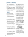
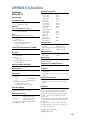
1
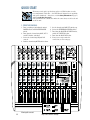
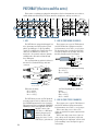
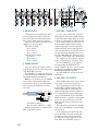
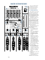
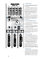
DFX SERIES
OWNER’S MANUAL
DFX•6 AND DFX•12
6- AND 12-CHANNEL MIXERS
WITH DIGITAL EFFECTS
DFX12 MIXER
12 CHANNEL COMPACT INTEGRATED LIVE SOUND MIXER
OPTIONAL USES FOR INSERTS
CAUTION
WARNING:
MANUFACTURING DATE
SERIAL NUMBER
TO REDUCE THE RISK OF FIRE OR ELECTRIC SHOCK, DO NOT
EXPOSE THIS EQUIPMENT TO RAIN OR MOISTURE. DO NOT REMOVE COVER.
NO USER SERVICEABLE PARTS INSIDE. REFER SERVICING TO QUALIFIED PERSONNEL.
RISK OF ELECTRIC SHOCK
DO NOT OPEN
STEREO
PLUG
MONO PLUG
AVIS: RISQUE DE CHOC ELECTRIQUE — NE PAS OUVRIR
UTILISE UN FUSIBLE DE RECHANGE DE MÊME TYPE.
DEBRANCHER AVANT DE REMPLACER LE FUSIBLE
REPLACE WITH THE SAME TYPE FUSE AND RATING.
DISCONNECT SUPPLY CORD BEFORE CHANGING FUSE
POWER
INSERT ALL THE WAY IN TO
THE "SECOND CLICK"
TIP OUT TO EFFECTS DEVICE
RING RETURN FROM EFFECTS
DIRECT OUT WITH SIGNAL
INTERRUPTION TO MASTER
FOR USE AS AN EFFECTS LOOP
(TIP = SEND, RING = RETURN)
CONCEIVED AND DESIGNED BY MACKIE DESIGNS INC • WOODINVILLE • WA • USA • MADE IN CHINA •FABRIQUE AU CHINE • COPYRIGHT ©2001 • THE FOLLOWING
ARE TRADEMARKS OR REGISTERED TRADEMARKS OF MACKIE DESIGNS INC.: "MACKIE", "EMAC", AND THE "RUNNING MAN" FIGURE • PATENT PENDING
ON
100 240 VAC, 50/60 Hz,
30 WATTS
1
2
3
4
5/6
7/8
MIC
MIC
MIC
MIC
MIC
MIC
11/12
9/10
STEREO AUX
RETURN
L
MAIN OUT
AUX SEND
R
LEFT
1
RIGHT
1
MON
(MONO)
2
2
EFX
BAL/UNBAL
LEVEL
SET
BAL/UNBAL
BAL/UNBAL
BAL/UNBAL
BAL/UNBAL
LINE IN
LINE IN
LINE IN
LINE IN
INSERT
INSERT
INSERT
INSERT
1
MIC
U
LEVEL
SET
2
MIC
U
LEVEL
SET
3
MIC
U
LEVEL
SET
4
MIC
U
BAL/UNBAL
L
LEVEL
SET
BAL/UNBAL
BAL/UNBAL
L
L
L
(MONO)
(MONO)
(MONO)
(MONO)
LINE IN
LINE IN
LINE IN
LINE IN
R
R
R
R
5/6
MIC
U
LEVEL
SET
7/8
MIC
U
9/10
LEVEL
SET
U
TAPE
OUT
CD/TAPE
IN
L
L
R
R
EFX
FOOT
SWITCH
BAL/UNBAL
PHONES
11/12
LEVEL
SET
POWER
DFX·12
U
12 CHANNEL INTEGRATED LIVE SOUND MIXER
MIN
-20dB
+30dB
+50
MIN
-20dB
GAIN
HI
-20dB
+30dB
MIN
-20dB
GAIN
+20dB
+40
MIN
-20dB
GAIN
+20dB
+40
-20dB
GAIN
-20dB
+20dB
EQ
U
HI
HI
+15
U
EQ
U
GAIN
GAIN
HI
12k
-15
+15
U
EQ
U
PHANTOM POWER
+48V
HI
12k
-15
+15
U
EQ
U
-15
+15
U
LOW
LOW
LOW
LOW
LOW
LOW
80Hz
80Hz
80Hz
80Hz
80Hz
80Hz
AUX
1
U
MON
+6
2
1
-15
2
1
U
U
-15
2
1
-15
2
1
U
OO
U
OO
2
U
OO
U
OO
1
U
OO
2
U
OO
2
U
OO
U
OO
BYPASS
0
NORM
4
1
MON
+6
EFX
+6
8
12K
4
EQ
DIGITAL STEREO
EFFECTS PROCESSOR
BYPASS
8
LEVEL SET
12
REVERSE
DELAY 1
GATE
DELAY 2
16
CATHEDRAL
DELAY 3
20
LG. HALL
DELAY 4
+6
(EFFECTS TO
STAGE MONITOR)
EFX
+6
1
3.5K
1K
MAIN
AUX 1
AUX
MON
+6
250
60
+15
AUX
MON
+6
EFX
+6
-15
+15
AUX
MON
+6
EFX
+6
OO
U
OO
U
EFX
+15
AUX
MON
+6
OO
+6
OO
+15
AUX
MON
+6
EFX
+6
OO
U
OO
U
EFX
+15
AUX
MON
+6
OO
+6
-15
– 12
– 12
80Hz
+15
16
12
+15
U
LOW
-15
LEFT RIGHT
CLIP
12k
12k
-15
0
0
HI
HI
12k
-15
+15
U
EQ
U
80Hz
+15
+12
+12
+20dB
75 Hz
12k
-15
+50
LOW
-15
U
MIN
LOW CUT
HI
+15
U
AUX
OO
+50
EQ
U
12k
-15
+15
OO
+30dB
75 Hz
EQ
U
12k
U
-20dB
LOW CUT
75 Hz
EQ
+15
U
-15
MIN
GAIN
LOW CUT
75 Hz
-15
+50
GAIN
LOW CUT
U
+30dB
2
MD. HALL
EFX
24
CHORUS
LG. PLATE
+6
30
FLANGE
MD. PLATE
0 = +4dBu
PHASER
SM. ROOM
SPRING
VOCAL
ELIMINATOR
U
U
L
PAN
1
R
L
MUTE
PAN
2
R
L
MUTE
PAN
3
R
L
MUTE
PAN
4
R
L
MUTE
PAN
5/6
R
L
MUTE
PAN
7/8
R
L
MUTE
PAN
9/10
R
L
MUTE
PAN
OO
R
+6
AUX 1/MON SEND
11/12 MUTE
AUX 1
RETURN
MUTE
OO
BREAK
SWITCH
+6
AUX 2/EFX SEND
AUX 2/EFX
RETURN
MUTE
OO
MAIN MIX
CD/TAPE
MUTE
RETURN
LEFT
dB
dB
dB
dB
dB
dB
dB
dB
dB
dB
dB
dB
10
10
10
10
10
10
10
10
10
10
10
10
OL
OL
OL
OL
OL
OL
OL
MAX
PHONES
(MUTES ALL MIC CHANNELS)
OL
5
5
5
5
5
5
5
5
5
5
5
5
U
U
U
U
U
U
U
U
U
U
U
U
5
5
5
5
5
5
5
5
5
5
5
5
10
10
10
10
10
10
10
10
10
10
10
10
20
20
20
20
20
20
20
20
20
20
20
20
30
30
30
30
30
30
30
30
30
30
30
30
40
50
60
40
50
60
40
50
60
40
50
60
40
50
60
40
50
60
40
50
60
40
50
60
40
50
60
40
50
60
40
50
60
40
50
60
OO
OO
OO
OO
OO
OO
OO
OO
OO
OO
OO
OO
RIGHT
CAUTION
AVIS
RISK OF ELECTRIC SHOCK
DO NOT OPEN
RISQUE DE CHOC ELECTRIQUE
NE PAS OUVRIR
CAUTION: TO REDUCE THE RISK OF ELECTRIC SHOCK
DO NOT REMOVE COVER (OR BACK)
NO USER-SERVICEABLE PARTS INSIDE
REFER SERVICING TO QUALIFIED PERSONNEL
ATTENTION: POUR EVITER LES RISQUES DE CHOC
ELECTRIQUE, NE PAS ENLEVER LE COUVERCLE. AUCUN
ENTRETIEN DE PIECES INTERIEURES PAR L'USAGER. CONFIER
L'ENTRETIEN AU PERSONNEL QUALIFIE.
AVIS: POUR EVITER LES RISQUES D'INCENDIE OU
D'ELECTROCUTION, N'EXPOSEZ PAS CET ARTICLE
A LA PLUIE OU A L'HUMIDITE
The lightning flash with arrowhead symbol within an equilateral
triangle is intended to alert the user to the presence of uninsulated
"dangerous voltage" within the product's enclosure that may be
of sufficient magnitude to constitute a risk of electric shock to persons.
Le symbole éclair avec point de flèche à l'intérieur d'un triangle
équilatéral est utilisé pour alerter l'utilisateur de la présence à
l'intérieur du coffret de "voltage dangereux" non isolé d'ampleur
suffisante pour constituer un risque d'éléctrocution.
The exclamation point within an equilateral triangle is intended to
alert the user of the presence of important operating and maintenance
(servicing) instructions in the literature accompanying the appliance.
Le point d'exclamation à l'intérieur d'un triangle équilatéral est
employé pour alerter les utilisateurs de la présence d'instructions
importantes pour le fonctionnement et l'entretien (service) dans le
livret d'instruction accompagnant l'appareil.
SAFETY INSTRUCTIONS
1. Read Instructions — All the safety and operation instructions should be
read before this Mackie product is operated.
2. Retain Instructions — The safety and operating instructions should be kept
for future reference.
3. Heed Warnings — All warnings on this Mackie product and in these operating
instructions should be followed.
4. Follow Instructions — All operating and other instructions should be
followed.
5. Water and Moisture — This Mackie product should not be used near water
– for example, near a bathtub, washbowl, kitchen sink, laundry tub, in a wet
basement, near a swimming pool, swamp or salivating St. Bernard dog, etc.
6. Cleaning — Clean only with a dry cloth.
7. Ventilation — This Mackie product should be situated so that its
location or position does not interfere with its proper ventilation. For
example, the Component should not be situated on a bed, sofa, rug, or
similar surface that may block any ventilation openings, or placed in a
built-in installation such as a bookcase or cabinet that may impede the
flow of air through ventilation openings.
8. Heat — This Mackie product should be situated away from heat sources
such as radiators, or other devices which produce heat.
9. Power Sources — This Mackie product should be connected to a power
supply only of the type described in these operation instructions or as marked
on this Mackie product.
10. Power Cord Protection — Power supply cords should be routed so that
they are not likely to be walked upon or pinched by items placed upon or
against them, paying particular attention to cords at plugs, convenience
receptacles, and the point where they exit this Mackie product.
11. Object and Liquid Entry — Care should be taken so that objects do not
fall on, and liquids are not spilled into, this Mackie product.
2
12. Damage Requiring Service — This Mackie product should be serviced
only by qualified service personnel when:
A. The power-supply cord or the plug has been damaged; or
B. Objects have fallen, or liquid has spilled into this Mackie product; or
C. This Mackie product has been exposed to rain; or
D. This Mackie product does not appear to operate normally or exhibits
a marked change in performance; or
E. This Mackie product has been dropped, or its chassis damaged.
13. Servicing — The user should not attempt to service this Mackie product
beyond those means described in this operating manual. All other servicing
should be referred to the Mackie Service Department.
14. To prevent electric shock, do not use this polarized plug with an
extension cord, receptacle or other outlet unless the blades can be fully
inserted to prevent blade exposure.
Pour prévenir les chocs électriques ne pas utiliser cette fiche polariseé avec un
prolongateur, un prise de courant ou une autre sortie de courant, sauf si les
lames peuvent être insérées à fond sans laisser aucune pariie à découvert.
15. Grounding or Polarization — Precautions should be taken so that the
grounding or polarization means of this Mackie product is not defeated.
16. Power Precaution — Unplug this Mackie product during lightning storms
or when unused for long periods of time.
17. This apparatus does not exceed the Class A/Class B (whichever is
applicable) limits for radio noise emissions from digital apparatus as set out in the
radio interference regulations of the Canadian Department of Communications.
ATTENTION —Le présent appareil numérique n’émet pas de bruits
radioélectriques dépassant las limites applicables aux appareils numériques de
class A/de class B (selon le cas) prescrites dans le règlement sur le brouillage
radioélectrique édicté par les ministere des communications du Canada.
18. Exposure to extremely high noise levels may cause permanent hearing
loss. Individuals vary considerably in susceptibility to noise-induced hearing loss,
but nearly everyone will lose some hearing if exposed to sufficiently intense
noise for a period of time. The U.S. Government’s Occupational Safety and
Health Administration (OSHA) has specified the permissible noise level exposures
shown in the following chart.
According to OSHA, any exposure in excess of these permissible limits
could result in some hearing loss. To ensure against potentially dangerous exposure to high sound pressure levels, it is recommended that all persons exposed
to equipment capable of producing high sound pressure levels use hearing protectors while the equipment is in operation. Ear plugs or protectors in the ear
canals or over the ears must be worn when operating the equipment in order
to prevent a permanent hearing loss if exposure is in excess of the limits set
forth here.
Duration Per Day
In Hours
8
6
4
3
2
1.5
1
0.5
0.25 or less
Sound Level dBA,
Slow Response
90
92
95
97
100
102
105
110
115
Typical
Example
Duo in small club
Subway Train
Very loud classical music
Patrice screaming at Ron about deadlines
Loudest parts at a rock concert
WARNING — To reduce the risk of fire or electric shock,
do not expose this appliance to rain or moisture.
About this manual:
This manual covers both the DFX•6 and DFX•12 mixers. They share the same design and
operate in the same way, except that the DFX•12 has 2 more mono channels than the DFX•6,
and it has 2 stereo line-only channels.
Absolutely most important pages:
Before connecting and using your mixer, please read the Safety Instructions
on page 2. Before you start mixing, please read the Quick Start section starting
on page 4. It’s a list of steps that will familiarize you with the mixer and help you
set up a basic performance.
CONTENTS
SAFETY INSTRUCTIONS ....................... page 2
QUICK START ............................................. 4
INTRODUCTION .......................................... 6
APPLICATION DIAGRAMS ............................ 7
PATCHBAY FEATURES
MIC .................................................... 8
LINE IN (MONO) .................................. 8
LINE IN (STEREO) ................................. 8
INSERT ................................................ 9
EFFECTS: SERIAL OR PARALLEL? ............. 9
MAIN OUTPUTS ................................. 10
PHONES ............................................ 10
AUX SEND 1/MON ............................ 10
AUX SEND 2/EFX ............................... 10
AUX 1 RETURN .................................. 11
AUX 2 RETURN .................................. 11
CD/TAPE INPUT ................................. 11
TAPE OUTPUT .................................... 11
EFX FOOTSWITCH ............................... 11
AC POWER INPUT .............................. 11
POWER SWITCH ................................ 11
CHANNEL STRIP FEATURES
GAIN ................................................ 12
LEVEL SET LED .................................... 12
LOW CUT .......................................... 12
2-BAND EQ ........................................ 12
HI EQ ............................................. 12
LOW EQ ......................................... 12
AUXILIARIES ...................................... 13
AUX 1/MON .................................. 13
AUX 2/EFX ..................................... 13
PAN .................................................. 13
MUTE ................................................ 13
FADER ............................................... 13
OL OVERLOAD LED ............................. 13
MASTER SECTION FEATURES
STEREO GRAPHIC EQ .................. page 14
MAIN/AUX 1 EQ SWITCH ................... 15
BYPASS EQ SWITCH............................ 15
POWER LED ....................................... 15
PHANTOM POWER SWITCH AND LED ... 15
METERS ............................................ 15
PHONES LEVEL ................................... 15
MAIN MIX FADERS ............................. 15
CD/TAPE RETURN FADER AND MUTE .... 15
BREAK SWITCH .................................. 16
VOCAL ELIMINATOR SWITCH ............... 16
AUX 2/EFX SEND ............................... 16
LEVEL SET LED .................................... 16
AUX 2/EFX RETURN FADER AND MUTE 17
AUX 1/MON SEND ............................ 17
EFFECTS TO MONITOR ........................ 17
AUX 1 RETURN FADER AND MUTE ....... 17
EMAC EFFECTS PROCESSOR ................. 17
QUICK START .................................. 17
BYPASS LED .................................... 17
PRESET SELECTION ........................... 18
APPENDIX A: SERVICE INFO
WARRANTY SERVICE .......................... 20
TROUBLESHOOTING ........................... 20
REPAIR ............................................. 20
APPENDIX B: TECHNICAL INFO
SPECIFICATIONS ................................. 21
DIMENSIONS ..................................... 22
AC POWER CONSIDERATIONS .............. 22
BLOCK DIAGRAM ............................... 23
Please visit our website at www.mackie.com
for more information about this and other Mackie products.
3
QUICK START
We know you can’t wait to get the show on the road. Who has time to read a
booooring manual? That’s fine — the DFX Mixer is designed to set up quickly
and operate intuitively — but please, read the Safety Instructions on page 2,
and then read these two pages!
First you will zero the console, then make the connections, set the levels and
tweak the mix.
1. ZERO THE CONSOLE:
5. Set the channel strip LOW CUT switches up.
6. Center the STEREO GRAPHIC EQ sliders.
7. Turn down the MASTER AUX SEND knobs,
and the AUX RETURN faders.
8. Turn down the MAIN MIX faders.
9. Now you are ready to make the
connections, see the next page.
1. Turn everything off, including the mixer’s
POWER switch and PHANTOM POWER
switch.
2. Turn down the channel strip GAIN, AUX 1
and AUX 2 knobs, and faders.
3. Center the channel strip EQ and PAN
controls.
4. Push the channel strip MUTE switches down.
1
2
3
4
5/6
7/8
MIC
MIC
MIC
MIC
MIC
MIC
11/12
9/10
STEREO AUX
RETURN
L
MAIN OUT
AUX SEND
R
LEFT
1
RIGHT
1
MON
(MONO)
2
2
EFX
BAL/UNBAL
BAL/UNBAL
BAL/UNBAL
LINE IN
LINE IN
INSERT
LEVEL
SET
1
MIC
U
2
MIC
U
INSERT
LEVEL
SET
3
MIC
U
BAL/UNBAL
4
MIC
U
LEVEL
SET
L
L
L
(MONO)
(MONO)
(MONO)
(MONO)
LINE IN
LINE IN
LINE IN
LINE IN
R
R
R
R
INSERT
LEVEL
SET
BAL/UNBAL
BAL/UNBAL
L
LINE IN
LINE IN
INSERT
LEVEL
SET
BAL/UNBAL
BAL/UNBAL
5/6
MIC
U
LEVEL
SET
7/8
MIC
U
9/10
LEVEL
SET
U
TAPE
OUT
CD/TAPE
IN
L
EFX
FOOT
SWITCH
L
R
BAL/UNBAL
PHONES
R
11/12
LEVEL
SET
POWER
DFX·12
U
12 CHANNEL INTEGRATED LIVE SOUND MIXER
MIN
-20dB
+30dB
+50
MIN
-20dB
GAIN
EQ
+15
U
AUX
1
MON
+6
2
EFX
+6
2
EFX
+6
OO
+15
1
+40
-20dB
-20dB
+20dB
+12
+12
+20dB
GAIN
GAIN
PHANTOM POWER
+48V
MON
EFX
OO
U
EFX
OO
U
MON
+6
2
+6
OO
1
OO
U
EFX
+6
OO
MON
+6
2
U
OO
U
U
MON
OO
EFX
OO
U
EFX
+6
OO
8
12K
EQ
BYPASS
0
NORM
4
1
+6
2
3.5K
DIGITAL STEREO
EFFECTS PROCESSOR
BYPASS
8
LEVEL SET
12
REVERSE
DELAY 1
GATE
DELAY 2
16
CATHEDRAL
DELAY 3
20
+6
(EFFECTS TO
STAGE MONITOR)
2
+6
U
MON
+6
MAIN
AUX 1
AUX
1
1K
4
80Hz
+15
AUX
1
250
60
LOW
-15
AUX
– 12
– 12
80Hz
+15
16
12
+15
U
LOW
-15
LEFT RIGHT
CLIP
12k
-15
80Hz
+15
0
0
HI
HI
+15
U
LOW
-15
EQ
U
12k
-15
AUX
OO
U
HI
+15
U
80Hz
U
EQ
U
12k
-15
+15
1
+6
2
EQ
U
LOW
-15
U
MON
+6
OO
+20dB
HI
AUX
OO
U
-20dB
12k
80Hz
-15
+6
OO
U
MIN
GAIN
+15
U
LOW
AUX
MON
+40
EQ
U
-15
80Hz
+15
U
+20dB
HI
+15
U
LOW
1
+6
OO
U
OO
U
-20dB
12k
-15
AUX
MIN
EQ
U
HI
-15
+50
GAIN
12k
80Hz
+15
+30dB
75 Hz
+15
U
LOW
-15
-20dB
EQ
U
-15
80Hz
MIN
GAIN
HI
+15
+50
LOW CUT
12k
-15
LOW
OO
+30dB
75 Hz
EQ
U
HI
U
-20dB
GAIN
75 Hz
+15
U
-15
MIN
LOW CUT
12k
-15
+50
LOW CUT
75 Hz
U
+30dB
GAIN
LOW CUT
2
EFX
+6
LG. HALL
DELAY 4
MD. HALL
CHORUS
LG. PLATE
FLANGE
MD. PLATE
24
30
0 = +4dBu
PHASER
SM. ROOM
SPRING
VOCAL
ELIMINATOR
U
U
L
PAN
1
R
L
MUTE
dB
PAN
2
R
L
MUTE
dB
PAN
3
R
L
MUTE
dB
PAN
4
R
L
MUTE
dB
PAN
5/6
R
L
MUTE
PAN
7/8
R
L
MUTE
PAN
9/10
R
L
MUTE
PAN
OO
R
+6
AUX 1/MON SEND
11/12 MUTE
AUX 1
RETURN
MUTE
AUX 2/EFX
RETURN
BREAK
SWITCH
+6
MUTE
OO
MAIN MIX
CD/TAPE
MUTE
RETURN
LEFT
dB
dB
dB
dB
10
10
10
10
5
5
5
5
5
5
5
5
5
5
5
U
U
U
U
U
U
U
U
U
U
U
U
10
OL
10
OL
dB
10
OL
dB
10
dB
10
dB
10
OL
OL
OL
10
OL
OL
5
5
5
5
5
5
5
5
5
5
5
5
10
10
10
10
10
10
10
10
10
10
10
10
20
20
20
20
20
20
20
20
20
20
20
20
30
30
30
30
30
30
30
30
30
30
30
30
40
50
60
40
50
60
40
50
60
40
50
60
40
50
60
40
50
60
40
50
60
40
50
60
40
50
60
40
50
60
40
50
60
40
50
60
OO
OO
OO
OO
OO
OO
OO
OO
OO
OO
OO
OO
Zeroing the console
Key to the control settings
MAX
PHONES
(MUTES ALL MIC CHANNELS)
5
10
4
OO
AUX 2/EFX SEND
RIGHT
2. MAKE THE CONNECTIONS:
4. TWEAK THE MIX:
1. Connect your amplifier’s outputs to your
speaker inputs (unless, of course, you have
powered monitors).
2. Plug all the sound system components into
suitable AC outlets, properly grounded and
capable of delivering adequate current.
3. Using XLR or 1/4" TRS cables, make
connections from your mixer’s MAIN OUT
to your amplification system’s line inputs.
4. Make connections from your microphones
and instruments to the mixer: Connect
balanced microphones to the mono channel
MIC jacks. (For condenser microphones,
engage the PHANTOM POWER switch,
located just above the meters). Connect
line-level instruments (synthesizers, guitar
effects, direct boxes) to the mono or stereo
channel LINE IN 1/4" TRS jacks.
5. ZERO THE CONSOLE as shown on the
previous page.
6. Turn all the power switches on, leaving the
amplifier’s switch for last.
7. Turn up the MAIN MIX faders to the
“–30” label, for now. We’ll crank it later on.
8. Now you are ready to set the levels:
1. Engage MUTE on all channels except your
rhythm section (drums & bass).
2. Adjust the rhythm section’s channel faders
to get a good balance of levels.
3. Un-mute the other active channels and
adjust their faders.
4. Now that you have a rough mix going, turn
up the MAIN MIX faders to a comfortable
listening level.
5. If the overall mix has an equalization
problem, make adjustments to the STEREO
GRAPHIC EQ. If an individual channel is
the problem, use its channel EQ instead.
6. Use the channel AUX 2/EFX knobs to send
signals to the EMAC internal effects
processor (and to any external effects
processor you might have). Then adjust the
AUX 2/EFX RETURN fader and experiment
with adding some effects to your main mix.
7. If you are playing into the CD/TAPE input,
try using the VOCAL ELIMINATOR to hear
its effect on centered vocals and start up a
bit of audience mass-Karaoke.
8. Depending on how much time you’ve got,
keep tweaking. Walk the room to see how it
sounds away from your mixer.
Keep tweaking.
3. SET THE LEVELS:
1. Choose one of the microphones or instruments you connected. Make some noise. If
it’s a microphone, sing at your normal
singing volume. If it’s a synthesizer, play it
at its normal output level.
2. While making noise, turn up that channel’s
GAIN control until the adjacent LEVEL
SET LED starts a-blinking.
3. Disengage (up) that channel’s MUTE.
4. Raise that channel’s fader to unity gain
(“U” label). You should be hearing your
noise now.
5. If necessary, apply channel EQ changes.
(You may need to compensate for level
changes with the channel fader.)
6. Check that the channel’s OL LED does not
come on. If it does, reset the GAIN and
adjust the EQ if required.
7. Repeat steps 1 through 6 for the remaining
active channels.
8. Stop making noise. Everyone: start making
music.
9. Now you are ready to tweak the mix:
KNOW THESE THINGS:
•
•
•
•
•
•
• Never listen to loud
music for prolonged
periods. Please see “Safety
Instructions” on page 2 for
information on hearing
protection.
Never plug amplifier outputs into anything
except speakers.
Never use guitar cables to connect amplifiers to speakers.
Before making connections to an external
amp or reconfiguring an amp’s routing, turn
the amp’s level (gain) controls down, turn
the power off, make the changes, turn the
power back on, and then turn the level
controls back up.
When you shut down your equipment, turn
off any external amplifiers first. When
powering up, turn on the amplifiers last.
Change your engine oil every 3,000 miles
and rotate your tires for even wear. Dad
would be proud of you.
Save the shipping box and packing material!
You may need them someday, and you probably
don’t want to have to pay for that again.
5
INTRODUCTION
Thank you for choosing a Mackie Designs
DFX™ Mixer! These compact live-sound mixers
are designed to meet the sound reinforcement
needs of almost any small to medium-sized club,
meeting room, sanctuary, or outdoor gathering.
Here’s a quick glance at all the features
you’ve acquired:
2 or 4 mono channels, with:
• Variable input gain
(0 to +50 dB mic, –20 to +30 dB line)
• Phantom power (globally switched)
• Level Set gain-setting indicator LED
• XLR microphone input jack
• 1/4" TRS line input jack
• 1/4" TRS insert jack
• Switchable 75 Hz low-cut filter
• Pre-fader aux (monitor) send
• Post-fader aux (effects) send
• 2-band EQ
• Pan control
• Mute switch
• Overload warning LED
• 60mm mono fader
Comprehensive master section, with:
• Two 60mm main mix faders (L, R)
• Balanced XLR stereo main outputs
• Balanced TRS stereo main outputs
• 12-segment stereo LED metering
• 5-band stereo graphic EQ with main mix/
monitor switch and bypass switch
• EMAC™ 32-bit digital stereo effects with
footswitch bypass, and Level Set LED
• Aux 1/monitor send with level control
• Aux 2/effects send with level control
• Effects-to-monitor control
• Two 60mm stereo aux return faders with
mute switches
• Break switch for intermissions
• RCA Tape output
• RCA CD/Tape input
• Vocal Eliminator circuit for CD/Tape
• Master +48 V phantom power switch
with LED indicator
• Headphone output with level control
• Power LED indicator
2 mono-mic / stereo-line channels, with:
• Variable input gain
(0 to +40 dB mic, –20 to +20 dB line)
• Level Set gain-setting indicator LED
• XLR microphone input jack
• Left and Right 1/4" TRS line input jacks
• Pre-fader aux (monitor) send
• Post-fader aux (effects) send
• 2-band EQ
• Pan control
• Mute switch
• Overload warning LED
• 60mm stereo fader
The DFX•12 also includes:
2 stereo-line channels, with:
• Variable input gain
(–20 to +20 dB line)
• Level Set gain-setting indicator LED
• Left and Right TRS line input jacks
• Pre-fader aux (monitor) send
• Post-fader aux (effects) send
• 2-band EQ
• Pan control
• Mute switch
• Overload warning LED
• 60mm stereo fader
6
Part No. 0000318 Rev. D 09/02
©2002 Mackie Designs Inc. All Rights Reserved.
Please write your serial number here for
future reference (i.e., insurance claims, tech
support, return authorization, etc.):
Purchased at:
Date of purchase:
APPLICATION
DIAGRAMS
Microphones 1-4
Active Monitor
Mono in/Stereo out Reverb
(optional)
1
2
3
4
5/6
7/8
MIC
MIC
MIC
MIC
MIC
MIC
11/12
9/10
STEREO AUX
RETURN
L
MAIN OUT
AUX SEND
R
LEFT
1
RIGHT
1
MON
(MONO)
2
2
EFX
BAL/UNBAL
BAL/UNBAL
BAL/UNBAL
LINE IN
LINE IN
INSERT
BAL/UNBAL
BAL/UNBAL
L
LINE IN
LINE IN
INSERT
BAL/UNBAL
INSERT
BAL/UNBAL
BAL/UNBAL
L
L
(MONO)
(MONO)
(MONO)
LINE IN
LINE IN
LINE IN
LINE IN
R
R
R
R
INSERT
TAPE
OUT
CD/TAPE
IN
L
(MONO)
L
L
R
EFX
FOOT
SWITCH
BAL/UNBAL
Active Speakers (SRM450s)
PHONES
R
Insert
Reverb
Headphones
Mono Effects
Tape Player
(optional)
Drum Machine
Compressor
DAT Recorder
Foot Switch
Bass
Guitar
DFX•12 — Small Club Gig
Amplifier (M1400)
Microphones
Passive Monitor (C300)
Mono in/Stereo out Reverb
(optional)
1
2
3/4
5/6
MIC
MIC
MIC
MIC
STEREO AUX
RETURN
L
MAIN OUT
AUX SEND
R
LEFT
1
RIGHT
1
MON
(MONO)
2
2
EFX
BAL/UNBAL
BAL/UNBAL
BAL/UNBAL
LINE IN
LINE IN
INSERT
INSERT
Insert
Insert
BAL/UNBAL
L
L
(MONO)
(MONO)
LINE IN
LINE IN
R
R
CD/TAPE
IN
TAPE
OUT
L
L
R
R
EFX
FOOT
SWITCH
BAL/UNBAL
PHONES
SR1530
Active Speakers
Compressors
(optional)
Laser Disc /DVD Player
CD/DVD Player
Routed through
Vocal Eliminator
Headphones
DFX•6 — Karaoke set up
7
PATCHBAY (the intro and the outro)
This is where everything gets plugged in: microphones, line-level instruments, effects devices,
and the ultimate destination(s): PA system, monitors, headphones, and tape recorder, etc.
1
2
3
4
5/6
7/8
MIC
MIC
MIC
MIC
MIC
MIC
11/12
9/10
STEREO AUX
RETURN
L
MAIN OUT
AUX SEND
R
LEFT
1
RIGHT
1
MON
(MONO)
2
2
EFX
BAL/UNBAL
BAL/UNBAL
BAL/UNBAL
LINE IN
LINE IN
BAL/UNBAL
BAL/UNBAL
LINE IN
BAL/UNBAL
L
LINE IN
L
(MONO)
INSERT
INSERT
INSERT
BAL/UNBAL
BAL/UNBAL
(MONO)
L
(MONO)
L
LINE IN
LINE IN
LINE IN
LINE IN
R
R
R
R
INSERT
CD/TAPE
IN
TAPE
OUT
EFX
FOOT
SWITCH
(MONO)
L
L
R
R
PHONES
1. MIC
2. LINE IN (FOR MONO CHANNELS)
The DFX Mixer is equipped with rugged, low
noise, phantom-powered microphone preamplifiers, providing up to 50 dB of pounding
crystal-clear amplification. Their balanced circuitry rejects all manner of extraneous
interference. Professional condenser, dynamic,
and ribbon mics all sound excellent through
these XLR inputs.
You can plug in almost any kind of balanced
mic that has a standard XLR-type male mic
connector.
These inputs can accept 1/4" TRS balanced
and 1/4" TS unbalanced plugs from any linelevel instrument, effects device, or tape player.
The line inputs share circuitry (but not phantom power) with the mic preamps, and can be
driven by virtually any line-level signal.
SLEEVE
HOT
COLD
SHIELD
3
TIP
SLEEVE
1/4" TS (Tip-Sleeve) unbalanced wiring:
Tip = hot (+)
Sleeve = shield
1
3
1
SLEEVE RING TIP
2
TIP
SHIELD
COLD
2
TIP
TIP
RING SLEEVE
COLD 3
HOT
1
SLEEVE
2
SHIELD
HOT
XLR balanced wiring:
Pin 1 = shield
Pin 2 = hot (+)
Pin 3 = cold (–)
The DFX Mixers provide +48 VDC phantom
powering on pins 2 and 3 of all the mono channels’ XLR MIC inputs (not the stereo channels).
This can be turned on or off using the PHANTOM
POWER (31) switch on the right side of the mixer.
DO NOT connect a linelevel device to a MIC input
with the phantom power
switched on. This could
damage the device. Use the
LINE IN (2, 3) jacks instead.
8
BAL/UNBAL
RING
TIP
SLEEVE
1/4" TRS (Tip-Ring-Sleeve) balanced
wiring:
Tip = hot (+)
Ring = cold (–)
Sleeve = shield
3. LINE IN (FOR STEREO CHANNELS)
These inputs can accept 1/4" TRS balanced
and 1/4" TS unbalanced plugs from any linelevel instrument, effects device, or tape player.
When connecting a stereo device (two
cords), use both the left (mono) input and the
right input.
When connecting a mono device (just one
cord), always use the left (mono) input and
plug nothing into the right input. A trick called
“jack normalling” causes the signal to appear
on both sides.
4. INSERT (FOR MONO CHANNELS)
EFFECTS: SERIAL OR PARALLEL?
Use the insert jacks to send the channel
signal through a compressor, graphic equalizer,
or similar device.
With nothing plugged into this jack, the
channel’s signal goes straight through the mic/
line preamp and channel strip. With an external effects device plugged into this jack, the
channel’s signal leaves the mixer, goes through
the effects device and back into the channel
strip (see insert plug diagram below).
The insert send signal is not affected by
the channel EQ or fader, thereby preserving
the original signal’s characteristics. Only the
GAIN (16) control has any effect on the insert
send level.
Specialty cables, developed just for these
insert jacks, are widely available. They allow a
signal to leave and enter the mixer on the
same TRS plug. They are wired thuswise:
Effects devices are used
either in serial or in parallel:
Serial means that the entire signal is routed through
the effects device. Examples
include: preamps, compressor/limiters, graphic equalizers. Connections are
typically made via the channel INSERT jacks.
Parallel means that a portion of the signal
is tapped off to the effects device, processed,
and returned, to be mixed with the original
“dry” signals. Multiple signals (via multiple
mixer channels) can all make use of the same
parallel effects device. Examples include:
reverb, delay, chorus. Connections are typically
made via AUX sends and AUX returns.
Tip = Send (to effects device input)
Ring = Return (from effects device output)
Sleeve = Common ground (connect shield
to all three sleeves)
tip
SEND to processor
ring
sleeve
(TRS plug)
This plug connects to one of the
mixer’s Channel Insert jacks.
Serial Device
Insert
Send
Insert
Return
Signal Processor
(e.g., Compressor)
Dry Signal
Processed
Signal
Parallel Device
“tip”
Aux
Send
Signal Processor
(e.g., Reverb)
“ring”
RETURN from processor
Besides being used for inserting effects devices, these jacks can also be used as channel
direct outputs; post-GAIN (16), pre-LOW CUT
(18) and pre-EQ (19, 20).
Here are three ways to use the jacks:
Aux
Return
Output
Section
Wet Signal
Mix
Stage
Channel Path
Dry Signal(s)
Dry Signal(s)
MONO PLUG
Channel Insert jack
Direct out with no signal interruption to master.
Insert only to first “click”
MONO PLUG
Channel Insert jack
Direct out with signal interruption to master.
Insert all the way in to the second “click”
STEREO
PLUG
Channel Insert jack
For use as an effects loop.
(TIP = SEND to effect, RING = RETURN from effects)
9
Processed
Signal
1
2
3
4
5/6
7/8
MIC
MIC
MIC
MIC
MIC
MIC
11/12
9/10
STEREO AUX
RETURN
L
MAIN OUT
AUX SEND
R
LEFT
1
RIGHT
1
MON
(MONO)
2
2
EFX
BAL/UNBAL
BAL/UNBAL
BAL/UNBAL
LINE IN
LINE IN
BAL/UNBAL
BAL/UNBAL
LINE IN
BAL/UNBAL
L
LINE IN
(MONO)
INSERT
INSERT
INSERT
INSERT
BAL/UNBAL
BAL/UNBAL
L
(MONO)
L
(MONO)
LINE IN
LINE IN
LINE IN
LINE IN
R
R
R
R
CD/TAPE
IN
TAPE
OUT
L
L
R
R
EFX
FOOT
SWITCH
BAL/UNBAL
PHONES
5. MAIN OUTPUTS
7. AUX SEND 1/MON OUTPUT
Coming in two flavors, XLR and 1/4" TRS,
the main output represents the end of the
mixer chain, where your fully mixed and enhanced stereo signal enters the real world.
Connect these outputs to the inputs of your
amplifier, or powered speakers.
XLR balanced wiring:
Pin 1 = shield
Pin 2 = hot (+),
Pin 3 = cold (–)
1/4" TRS balanced wiring:
Tip = hot (+)
Ring = cold (–)
Sleeve = shield
To create a stage monitor mix, patch this
TRS output into your monitor amplifier’s input,
or powered monitor’s input. This jack can also
be used to feed the inputs of an effects device.
Each channel strip has an AUX 1 (21) control knob which adjusts how much of that
channel’s signal appears at this output. The
output from this jack is the sum of all those
active channels which have their AUX 1 knobs
set more than in the minimum position. Use
the AUX 1/MON SEND (41) knob (page 17) to
control the overall output sent to your monitor.
The output is not affected by the main mix
faders, or channel faders, or by channel EQ.
The five band EQ (27) can be applied to
this output using the MAIN/AUX 1 (28)
switch. A sample of the stereo effects can also
be added to your monitor by adjusting the
EFFECTS TO MONITOR (42) knob.
See AUX 1/MON (21) on page 13 for more
information.
6. PHONES OUTPUT
The stereo signal at this output jack is the
main mix, but it is not affected by the position
of the MAIN MIX (34) faders.
The PHONES (33) control knob allows you
to set the levels in your headphones as desired,
without disturbing the main mix level.
Note: Be very careful because the PHONES
jack can drive any standard headphones to
very loud levels. Please see the “Safety Instructions” on page 2 for information on hearing
protection.
RING SLEEVE
SLEEVE RING TIP
TIP
RING
TIP
SLEEVE
1/4" TRS stereo wiring:
Tip = left, ring = right, sleeve = shield
Walkperson-type phones can also be used
with an appropriate adapter.
10
L
(MONO)
8. AUX SEND 2/EFX OUTPUT
This 1/4" TRS output can be used to connect
to the input of an external effects device.
Each channel strip has an AUX 2 (22) control knob which adjusts how much of that
channel’s signal appears at this output. The
output from this jack is the mix of all those active channels which have their AUX 2 knobs
set more than minimum. Use the AUX 2/EFX
SEND (38) knob to control the overall output
sent to your external effects processor. The
EMAC internal effects processor receives the
same signal.
This output is not affected by the main mix
faders, the five-band EQ (27), or by the EMAC
internal effects.
As the output is post-channel-fader, and
post-channel EQ, it cannot be used as traditional stage monitor cues. It is intended to
patch into effects device inputs; hence the
name “EFX.” See AUX 2/EFX on page 13.
9. AUX 1 RETURN INPUTS
Patch the outputs of external parallel effects devices to these inputs.
Signals coming in are adjusted using the
AUX 1 RETURN (43) fader and MUTE.
When connecting a mono device (just one
cord), always use the left (mono) input and
plug nothing into the right input. The signal
will appear on both sides.
10. AUX 2 RETURN INPUTS
Patch the outputs of external parallel effects devices to these inputs.
Signals coming in are adjusted using the
AUX 2 RETURN (40) fader and MUTE.
When connecting a mono device (just one
cord), always use the left (mono) input and
plug nothing into the right input. The signal
will appear on both sides.
Note: The AUX 2 RETURN signal is combined with the signal from the internal
effects processor.
11. CD/TAPE INPUT
Patch the outputs of your intermission
entertainment here. Any line-level mono or
stereo device can be used: tape, DVD/CD
player, television audio, etc.
Signals coming into the CD/TAPE (11) inputs are adjusted using the CD/TAPE RETURN
(35) fader and MUTE.
Also see page 16 for information regarding
the BREAK (36) switch.
SLEEVE TIP SLEEVE TIP
RCA unbalanced wiring:
Tip = hot, sleeve = shield
When connecting a mono device (just one
cord), you’ll need a “Y-splitter” RCA adapter. It
turns a mono output cord into two cords; so
both the left and right tape input jacks can be
used. This adapter is widely available.
Note: There is a chance of feedback if you
have the ins and outs connected to the same
recorder, and it is in record mode.
12. TAPE OUTPUT
Use these jacks to capture the entire performance to tape. The signal at these jacks is the
main mix, but it is not affected by the position
of the MAIN MIX (34) faders.
If you find that the output to tape is quite
low in level, but your main speaker sound levels are good, you might try turning down the
level controls of your amplifiers a little. Adjust
the channel faders upwards to compensate.
This will increase the levels in the mixer and
the tape output.
13. EFX FOOTSWITCH
You can connect a normally-open footswitch
here to switch the EMAC effects processor in
and out. Closing the switch connection causes
the internal effects to be bypassed, as you bask
in the warm glow of the BYPASS LED (44).
Note: This only affects the internal effects
and does not affect any signals from devices
plugged into AUX 1 and AUX 2 returns.
SLEEVE
SLEEVE
TIP
TIP
TIP
SLEEVE
1/4" TS (Tip-Sleeve) Footswitch wiring:
Tip = one end of a normally-open switch
Sleeve = shield, and other end of a
normally-open switch.
14. AC POWER INPUT
This IEC socket
on the rear panel,
is where you connect the supplied
AC linecord to provide AC power to
POWER
the mixer. Plug
the cord into a
suitable AC outlet,
properly grounded
and capable of delivering adequate
current.
The mixer has a universal-input, switching
power supply, so you can plug the AC linecord
into any AC outlet with a nominal voltage
between 100 and 240 VAC, without having to
worry about setting any switches or using a
step-up or step-down voltage transformer.
ON
100 240 VAC, 50/60 Hz,
30 WATTS
15. POWER SWITCH
Push the side of the switch labeled “ON” to
turn the mixer on; you should see the POWER
LED (30) glow in confirmation on the top
right of the mixer. To turn the mixer off, push
the switch the other way.
As a general rule, turn the mixer on first,
before any amplifiers or powered speakers,
and at the end of a show, turn it off last. This
will prevent any turn-on or turn-off thumps
being heard in your speakers.
11
LEVEL
SET
1
MIC
U
MIN
-20dB
+30dB
+50
GAIN
LOW CUT
75 Hz
EQ
U
HI
12k
-15
+15
U
LOW
80Hz
-15
+15
AUX
U
MON
+6
OO
U
2
EFX
+6
OO
L
1
PAN
1
R
MUTE
dB
10
OL
5
U
CHANNEL STRIP FEATURES
OVERVIEW
18. LOW CUT
The channel strips are independent of each
other, and allow you to adjust, tweak and otherwise beautify the sound coming from your
different microphones, guitars and other instruments. The Faders and Pans let you adjust
how much of each channel is sent to the main
mix. The Auxes let you adjust how much of
each channel goes to your stage monitors or
out to external or internal effects.
The channel strips come in two flavors:
Mono and Stereo. In addition, the DFX•12 has
two line-level-only stereo channels.
The LOW CUT circuit, often referred to as a
high-pass filter, cuts the bass frequencies
below 75 Hz at a rate of 18 dB per octave.
We recommend that you use LOW CUT on
every microphone application except kick
drum, bass guitar, or bass-heavy synth patches.
LOW CUT can also help reduce the possibility
of feedback in live situations and it helps to
conserve amplifier power.
16. GAIN
If you haven’t already, please read “SET
THE LEVELS” on page 5.
The GAIN control adjusts the input sensitivity of the mic and line inputs on each channel.
This allows signals from the outside world to be
adjusted to optimal internal operating levels.
Through the mono channel MIC (XLR) inputs, there is 50 dB of gain fully up. For stereo
channel MIC inputs, this is +40 dB.
Through the mono channel LINE IN (TRS)
inputs, there is 20 dB of attenuation fully down
and +30 dB of gain fully up, with a “U” (unity
gain) mark halfway up. The stereo channel
LINE INs have a maximum gain of +20 dB.
Having 20 dB of line-level attenuation can
be very handy when you are injecting a signal
that is very hot, or when you want to add a lot
of EQ boost, or both. Without this “pad,” it
would be very difficult to control the line signal and might lead to channel clipping.
5
17. LEVEL SET LED
10
This LED (Light Emitting Dohickey) lets
you know that the signals going into the mixer
are adjusted to the correct level, not too strong
to cause distortion and not too weak to be lost
in noise.
After you connect a microphone or linelevel component to the mixer, do a sound test
and adjust the GAIN (16) control until this
handy LED flickers just occasionally. If it is
glowing constantly, turn the GAIN down. If the
LED is doing almost nothing, turn it up.
20
30
40
50
60
OO
Mono Channel
12
2-BAND CHANNEL EQ
The DFX Mixers use “shelving” equalization.
This boosts or cuts all frequencies past a specified frequency. For example, turning the
LOW EQ (20) knob clockwise will boost the
bass frequencies at 80 Hz and below.
Although you can bring sound to life with
proper EQ, you can also mess things up. If you
max the EQs on every channel, you’ll get mix
mush, not to mention driving your mix levels
near or beyond clipping. So equalize subtly;
use cut as well as boost.
Adjusting the channel EQ will affect your
main mix and the AUX 2/EFX (8) output, but
not the AUX 1/MON (7) output.
19. HI EQ
This control provides up to
15 dB of boost, or 15 dB of cut
at 12 kHz and above. There is
no boost or cut at the center
detent position.
Use this wisely to add sizzle to cymbals or
an overall sense of transparency or edge to
keyboards, vocals, guitar, and bacon frying.
Turn it down a little to reduce sibilance or
hide tape hiss.
+15
+10
+5
0
HI
–5
–10
–15
20Hz
100Hz
1kHz
10kHz 20kHz
20. LOW EQ
This control provides up
to 15 dB of boost, or 15 dB of
cut at 80 Hz and below.
There is no boost or cut at
the center detent position.
Frequencies of 80 Hz and
below represents the punch in bass drums,
bass guitar, fat synth patches, and
high-testosterone male singers.
While adding boost, also engaging the
LOW CUT (18) switch can create an audible
low frequency boost without boosting stage
rumble, mic-handling clunks, and breath pops.
+15
+10
+5
LOW
0
–5
–10
–15
20Hz
100Hz
1kHz
10kHz 20kHz
AUXILIARIES
AUX 1/MON allows you to create a separate
mono mix which can be used to feed stage
monitors.
AUX 2/EFX allows you to create another
mono mix to feed the EMAC internal effects,
and any external effects processor you have.
The channel AUX knobs adjust how much
of each channel is added to each aux mix. The
adjustment ranges from off, through unity, and
on up to 6 dB of extra gain.
The stereo channel AUX knobs control a
mono sum of the channel’s stereo signals. For
example, on the DFX•12, channel 9 (L) and
10 (R) mix together to feed that the channel
9/10 AUX knobs.
The master AUX SEND (38, 41) knobs adjust the overall aux output levels.
These are more than mere effects and
monitor sends: they can be used to generate
separate mixes for recording or “mix-minuses”
for broadcast.
21. AUX 1/MON
AUX 1 is designed for feeding a separate
monitor mix to the musicians on stage, via the
AUX 1 SEND (7) output jack.
The signal is tapped off before the channel
EQ section, and before the channel fader. Only
the channel GAIN, MUTE and LOW CUT will
affect the output to your monitors.
22. AUX 2/EFX
AUX 2 is designed for feeding the EMAC internal effects processor and the inputs of
parallel effects devices.
It is post-fader, so any changes to the channel controls will affect the AUX 2 signal. In
addition to feeding the inputs of the EMAC, it
also feeds the AUX 2 SEND (8) output.
23. PAN
This adjusts how much of the channel signal is playing in the left side of the main mix,
and how much is playing in the right.
For mono channels, if the PAN control is in
the center position, the mono signal appears
equally in both the left and right of the main
mix. If the control is set left, more of the signal
appears in the left side of the main mix. If the
control is set right, more of the signal appears
in the right side of the mix.
For stereo channels, the PAN control works
like the balance control on your home stereo,
by attenuating one side or the other. If it is in
the center position, the left and right channel
signals pass through to the main mix unaffected.
If PAN is turned left, the right channel is attenuated; if turned right, the left side is attenuated.
24. MUTE
11/12
LEVEL
SET
U
-20dB
+20dB
GAIN
When you engage a channel’s MUTE switch,
its signal disappears from the main mix, tape,
AUX 1, AUX 2 and headphones. The only exception is the INSERT (4) outputs.
EQ
U
HI
25. FADER
12k
This fader is the master level control for
the channel’s signal. Subtle adjustment of the
channels’ fader positions is the key to a finelytuned mix.
Typically (providing the GAIN (16) control
is set correctly) the fader position will be positioned somewhere between 0 dB (“U”) and
–30 dB.
If you have a fader set all the way up, that’s
usually a sign that your GAIN is set too low.
Conversely, if the fader is set way down, your
GAIN may be set too high.
-15
+15
U
LOW
80Hz
-15
+15
AUX
U
1
MON
+6
OO
U
2
EFX
+6
OO
“U” = UNITY GAIN
Mackie mixers have a “U”
mark on almost every level
control. This stands for
“unity gain,” meaning there
is no change in signal level. Once you have adjusted the input signal to line-level, you can
set every control at “U” and your signals will
travel through the mixer at optimal levels.
What’s more, all the labels on our level controls are measured in dog biscuits (dB), so
you’ll know what you’re doing level-wise if you
choose to change a control’s settings.
L
PAN
R
11/12 MUTE
dB
10
OL
5
U
26. OL (OVERLOAD) LED
5
This handy feature gives you the chance to
take care of any signal overload before it is
made worse by turning up the fader.
This LED only lights when the channel’s signals are set too high and are about to distort
(clip). The OL circuit monitors the signal just
before it reaches the channel fader, so any
overload must be taken care of by adjusting the
channel’s GAIN, EQ, or the LOW CUT, and not
the channel fader.
If the LED comes on, make sure you reset
the GAIN control correctly, and check that
your channel EQ settings are not too high.
10
20
30
40
50
60
OO
Stereo Channel
(DFX•12)
13
MASTER SECTION FEATURES
POWER
DFX·12
12 CHANNEL INTEGRATED LIVE SOUND MIXER
+12
+12
27. STEREO GRAPHIC EQ
PHANTOM POWER
+48V
0
0
LEFT RIGHT
16
CLIP
12
– 12
– 12
250
60
3.5K
1K
8
12K
4
MAIN
AUX 1
EQ
BYPASS
0
NORM
4
DIGITAL STEREO
EFFECTS PROCESSOR
U
OO
(EFFECTS TO
STAGE MONITOR)
BYPASS
8
LEVEL SET
12
REVERSE
DELAY 1
GATE
DELAY 2
16
CATHEDRAL
DELAY 3
20
LG. HALL
DELAY 4
MD. HALL
CHORUS
LG. PLATE
FLANGE
+6
MD. PLATE
24
30
0 = +4dBu
PHASER
SM. ROOM
SPRING
VOCAL
ELIMINATOR
U
U
OO
+6
OO
AUX 1/MON SEND
AUX 1
RETURN
MUTE
AUX 2/EFX SEND
AUX 2/EFX
RETURN
BREAK
SWITCH
+6
MUTE
OO
MAX
PHONES
(MUTES ALL MIC CHANNELS)
MAIN MIX
CD/TAPE
MUTE
RETURN
LEFT
dB
dB
dB
dB
10
10
10
10
5
5
5
5
U
U
U
U
5
5
5
5
10
10
10
10
20
20
20
20
30
30
30
30
40
50
60
40
50
60
40
50
60
40
50
60
OO
OO
OO
OO
14
Before you read this chapter,
you might want to look at the
rather lovely channel strip features on the previous page.
RIGHT
This equalizer is used to shape
the frequency spectrum of the
main mix or monitor mix. It is
the last thing in the signal chain
before the MAIN MIX (34) faders
and the MAIN OUT (5) jacks.
Each EQ slider controls a different section of the audio
frequency range. Moving a slider
up or down will boost or cut the
output levels of signals around
the slider’s center frequency. By
setting all the EQ sliders to zero
(center) you’ll effectively remove
it from the signal path.
The following steps show how
the equalizer can be used to
reduce feedback:
1. Set the EQ sliders to zero
(center) while the band
plays on.
2. Set the channel GAIN (16)
levels, using the LEVEL
SET LED (17) and adjust
the channel faders for a
nice mix.
3. Slowly turn up the MAIN
MIX (34) faders until feedback just begins to occur.
BE CAREFUL! Feedback
can occur quickly and become very LOUD, very fast.
4. Cut the appropriate EQ slider
until the feedback stops.
Here are some general suggestions on using the EQ:
For better vocal sound, set the
250, and 12K sliders to +5.
Note: Make sure the singer
is within 3 to 6 inches of the
microphone. No amount of
EQ can save a wandering
minstrel.
For more presence, set the 3.5K
slider to +5.
To warm up the overall sound,
set the 1K slider to –5.
REMEMBER, LESS IS BETTER.
28. MAIN/AUX 1 EQ SWITCH
This switch allows you to add EQ either to
your main mix, or to your monitors.
In the UP (MAIN) position, the EQ (27)
only affects the main mix, phone or tape outs.
In the DOWN (AUX 1) position, the EQ only
affects the AUX SEND 1/MON (7) output; with
no effect on the main mix, phone or tape outs.
29. BYPASS EQ SWITCH
Use this switch to quickly compare the
effect of your EQ settings.
In the UP position, the EQ (27) section is
in line with the signal path, (either main mix
or monitor, depending on the position of the
MAIN/AUX 1 (28) switch).
In the DOWN position, the EQ section is bypassed and has no effect on any outputs.
30. POWER LED
This LED turns on when the mixer is
switched on, and (as you can probably guess)
it turns off when the mixer is switched off.
31. PHANTOM POWER SWITCH and LED
Press this switch to turn on the pretty LED.
It also supplies phantom power to all of the
mono channels’ XLR MIC inputs. Phantom
power is required to operate most condenser
microphones (some condenser microphones
are battery-powered). With the switch pressed
in, the DFX Mixers provide +48 VDC phantom
powering on pins 2 and 3 of the XLR connectors.
Note: The stereo channels do not have
phantom power on their XLR connectors.
If you have dynamic, ribbon, or tube mics
that do not require phantom power, leave the
switch out. If you are using both condenser and
dynamic mics, don’t worry. Phantom power will
not hurt most dynamic mics. Check the
microphone’s user manual if you’re not sure.
Caution: Turn all output
levels down before operating this switch to avoid the
possibility of a “pop” in your
speakers.
32. METERS
The DFX Mixer’s metering system is made
up of two columns of twelve LEDs each, with
thresholds ranging from –30 dB up to “CLIP.”
The 0 dB LEDs correspond to an output
level of +4 dBu (=1.23 V). The “CLIP” LEDs
turn on when the output reaches +20 dBu.
There is a fair margin of safety before actual
clipping distortion occurs, but you should turn
things down if you see it come on.
The meters display the level of the main
mix, after the MAIN MIX (34) faders.
You can get a good mix with the meter’s
peaks flashing anywhere between –20 and
+8 dB. Most amplifiers clip at about +10 dB,
and some recorders aren’t so forgiving either.
For best real-world results, try to keep your
peaks between “0” and “+8.”
If your meters are too high, you will get distortion. If they are too low, then your signal/
noise will suffer. Use the meters to help you
adjust the mixer for optimum performance
without distortion or noise, then you can
adjust your amplifiers for good overall volume.
33. PHONES
This control allows you to adjust the headphone levels without disturbing the main mix.
Turn this down before connecting and putting on your headphones. Bring it up slowly.
Please see the “Safety Instructions” on page
2 for information on hearing protection.
34. MAIN MIX FADERS
These two faders control the final level of
the signals sent to the MAIN (5) outputs.
The TAPE (12) and PHONE (6) outputs
also receive the main mix, but are not affected
by these faders.
All active mono and stereo channels that
are not turned fully down will appear in the
main mix. Other signals feeding these faders
include: AUX 1 RETURN(9), AUX 2 RETURN
(10) including the EMAC internal effects, and
the CD/TAPE (11) inputs.
The faders, set fully up, provide 10 dB of
gain. A “U” unity gain point is just below that.
When set fully down, the main mix is effectively muted. These are the faders to pull
down at the end of the song when you want
The Great Fade-Out.
35. CD/TAPE RETURN FADER and MUTE
If you have a CD or Tape player connected to
the CD/TAPE (11) inputs, the signals pass through
the MUTE switch, through this stereo fader, and
then into your main mix. This is like a channel
fader, except it is adding the CD/TAPE input to
the main mix, instead of adding a channel.
Set this fader to minimum, then play your
selection and increase the fader as desired.
Assuming the MAIN MIX (34) faders are set,
you should hear the music. Press down the
VOCAL ELIMINATOR (37) if you like to
remove centered vocals, and BREAK (36) if
you want to play soothing CDs or tapes
while the band is breaking up the bar.
15
36. BREAK SWITCH
DFX·12
12 CHANNEL INTEGRATED LIVE SOUND MIXER
+12
+12
0
0
– 12
– 12
250
60
1K
MAIN
AUX 1
3.5K
EQ
BYPASS
DIGITAL STEREO
EFFECTS PROCESSOR
U
OO
BYPASS
LEVEL SET
REVERSE
DELAY 1
GATE
DELAY 2
CATHEDRAL
DELAY 3
LG. HALL
DELAY 4
MD. HALL
CHORUS
LG. PLATE
FLANGE
MD. PLATE
PHASER
+6
(EFFECTS TO
STAGE MONITOR)
12K
SM. ROOM
SPRING
VOCAL
ELIMINATOR
U
U
OO
+6
AUX 1/MON SEND
AUX 1
RETURN
MUTE
OO
AUX 2/EFX SEND
AUX 2/EFX
RETURN
BREAK
SWITCH
+6
MUTE
(MUTES ALL MIC CHANNELS)
CD/TAPE
MUTE
RETURN
dB
dB
dB
10
10
10
5
5
5
U
U
U
5
5
5
10
10
10
20
20
20
30
30
30
40
50
60
40
50
60
40
50
60
OO
OO
OO
Engage the BREAK switch (as in take-abreak) and the entire main microphone mix
is switched off.
The CD/TAPE (11) input is still active, so
you can play your intermission CDs or tapes
through the main outputs. On the DFX•12,
line level inputs 9 and 10, 11 and 12 are also
still active, and are summed with the CD/
TAPE input. During an intermission, you
could play keyboards or a second tape deck
into these line inputs.
BREAK acts as a master mute switch for
your microphones, so it is useful when moving
microphones around on stage. It does not
mute the AUX 1 (7) or AUX 2 (8) outputs, so
turn down the master AUX SEND (41, 38)
knobs if desired.
37. VOCAL ELIMINATOR SWITCH
This switch allows you to eliminate the vocals from any CD or Tape selection playing in
the CD/TAPE (11) inputs.
In the UP position, the CD or Tape signals
are not affected. In the DOWN position, any
vocals which are centered in the normal stereo image will be attenuated.
The circuit design uses phase cancellation
of the vocal frequency range between the left
and right channels. The effect is most noticeable on music material which has the vocals
panned dead center.
38. AUX 2/EFX SEND
Effects send signals are derived by each
channel’s AUX 2/EFX (22) control, summed
together, then sent through this master control. It allows you to simultaneously adjust the
signal levels out to the AUX 2/EFX SEND (8)
output, and to the EMAC effects processor.
Turned fully up, it provides 6 dB of gain,
“U” is unity gain, and fully down is off.
Use the individual channel AUX 2/EFX
controls to adjust the amount of each
channel’s signal you want to go to the AUX 2/
EFX SEND or EMAC. Then use this master
control to make sure the EMAC’s LEVEL SET
LED (39) never lights more than occasionally.
39. LEVEL SET LED
This indicates when the EMAC is 6 dB below clipping. Just like the channel LEVEL SET
LEDs (17), this should only light occasionally.
If it blinks frequently, you should turn down the
AUX 2/EFX SEND (38) control a little. If this
LED never blinks, then turn the control up.
16
40. AUX 2/EFX RETURN FADER, MUTE
EMAC EFFECTS PROCESSOR
The EMAC output is added to any signals
going into the AUX 2 RETURN (10) jacks from
an external effects processor. The final effects
signal is then sent to this MUTE switch and
stereo fader. It acts like a channel fader, except it is adding the final effects signal to the
main mix, rather than adding a channel signal.
Turned fully up, it provides 10 dB of gain,
“U” is unity gain, and fully down is off.
Press MUTE to quickly compare the difference between adding, or not adding effects.
The MUTE and fader affect the level of the
effects going to the main mix only, and not of
any effects going to the monitors.
EMAC stands for Extended Multiply and Accumulate, which is a proprietary 32-bit digital
stereo processor developed by our Digital Engineering Group. It provides you with a choice
of 16 preset digital effects algorithms for your
enjoyment.
The mono signal going into the EMAC
comes from the AUX 2/EFX (22) controls of
each channel, summed together and passed
through the AUX 2/EFX SEND (38) control.
Note that the AUX 2/EFX signals are postchannel EQ and post-channel fader, so any
channel adjustments will alter the effects.
The EMAC takes the mono input, processes
it and creates a stereo output. A footswitch allows the EMAC to be bypassed and a SET
LEVEL LED (39) allows the input signal
strength to be optimized for best performance.
The processed stereo signals coming out of
the EMAC are added to any signals coming in
from an external processor connected to the
AUX 2 RETURN (10) jacks. The combined signals then pass through the MUTE (40) and
AUX 2/EFX RETURN (40) fader and then on
to the main mix.
41. AUX 1/MON SEND
This allows you to control the level of the
signal going out to your monitors.
Any signals from each channel’s AUX 1/MON
(21) control (and the EFFECTS TO MONITOR
(42) control), are summed together, then sent
through this master control.
Turned fully up, it provides 6 dB of gain,
“U” is unity gain, and fully down is off.
When the talent wants a louder monitor
mix, this is the control to crank up — watch
out for feedback!
42. EFFECTS TO MONITOR
Typically, this control is used to add effects to
the stage monitors. Any effects sent to the monitors are the same as in the main mix, except
for the level, and they are summed mono. The
effects level sent to the monitor mix is not affected by the AUX 2/EFX RETURN (40) fader,
so the monitors and main mix effect levels can
be set independently.
Turned fully up, this control provides 6 dB
of gain, and “U” is unity gain. Turn it fully
down for no effects sent to your monitors.
This control is similar to each channel’s
AUX 1/MON (21) control, except it adds the effects (summed mono) to the monitor mix,
rather than adding a channel signal.
43. AUX 1 RETURN FADER and MUTE
Any signals going into the AUX 1 RETURN
(9) jacks from an external processor pass
through the MUTE switch and then to this stereo fader. This is like a channel fader, except it
is adding the signal from an external device to
the main mix, rather than adding a channel
signal. Turned fully up, it provides 10 dB of
gain, “U” is unity gain, and fully down is off.
EMAC QUICK START
Assuming you have your basic mix up and
running, turn up the AUX 2 /EFX (22) controls
on each channel. This feeds individual
amounts of channel signals to the EMAC.
Set the master AUX 2 /EFX SEND (38) control so the EMAC’s LEVEL SET LED (39)
blinks occasionally.
Turn up the AUX 2/EFX (40) fader and you
should be hearing the effects.
Next, goof around with the various Preset
Selects (45) to listen to their effect. When you
find an effect you like, jot it down, then goof
around some more.
To bypass these effects, engage an optional
foot switch connected to EFX FOOT SWITCH
(13). To send these effects to the stage monitors, turn up the EFFECTS TO MONITOR (42)
knob.
44. BYPASS LED
This LED will come on when the EMAC circuit is bypassed by use of an external
footswitch. The bypass affects only the internal
EMAC effects, not any external effects processor you may have connected to the AUX 2
RETURN (10) jacks.
17
DIGITAL STEREO
EFFECTS PROCESSOR
U
OO
LEVEL SET
REVERSE
DELAY 1
GATE
DELAY 2
CATHEDRAL
DELAY 3
LG. HALL
DELAY 4
MD. HALL
CHORUS
LG. PLATE
FLANGE
MD. PLATE
PHASER
+6
(EFFECTS TO
STAGE MONITOR)
BYPASS
SM. ROOM
SPRING
VOCAL
ELIMINATOR
U
U
OO
+6
OO
AUX 1/MON SEND
AUX 1
RETURN
MUTE
+6
AUX 2/EFX SEND
AUX 2/EFX
RETURN
MUTE
BREAK
SWITCH
(MUTES ALL MIC CHANNELS)
CD/TAPE
MUTE
RETURN
45. PRESET SELECT
Rotate this detented switch to select any of
the following preset effects:
REVERBS
The reverbs are designed to provide a wide
variety of reverb sounds for vocal and instrument applications. In the following description,
“tail” refers to the reflections that follow the initial sound event, also referred to as decay
range. “Pre-delay” is the amount of time
between the initial sound event and the first
reflection.
REVERSE:
Standard reverse reverb, simulating a
tail-first effect increasing to the original
note.
GATED:
Standard gated reverb, where the reverb
tail is cut off sharply after the preset
decay length.
CATHEDRAL:
Dense, smooth reverb with very long tail,
long pre-delay, and late reflections. Tails
are very warm with some additional highend reflections imitating the stone walls
of a cathedral. A very dramatic effect
that works well with wind instruments
such as flute, slow finger picking on
acoustic guitar, and quiet vocal group
harmony and choirs. Also works well with
keyboards.
LG. HALL:
Dense, smooth reverb with long tail, long
pre-delay, and some early reflections.
Tails are warm with more apparent high
end. Works well with vocals and electric
and acoustic guitar.
18
MD. HALL:
Dense, smooth reverb with normal tail,
normal pre-delay, and increased early
reflections. Tails are warm with more
apparent high end. Works well with
vocals and electric and acoustic guitar.
LG. PLATE:
Good early reflections and no pre-delay.
Tails are normal and warm with strong
high end for increased presence. Perfect
for vocals and snare.
MD. PLATE:
Good early reflections and no pre-delay.
Tails are short and warm with strong high
end for increased presence. Perfect for
tight vocals and snare.
SM. ROOM:
Reverb featuring very fast and scattered
early reflections with a short pre-delay.
Tails are very short and warm with
normal high-end imitating absorbent wall
materials and audience. Good for tight
vocal effects.
SPRING:
Mimics the vintage 60’s-style wet spring
reverb effect. Tails are normal with strong
high end and a slight waver imitating the
slow flutter of the mechanical spring
system. Very good with acoustic guitar.
DELAYS
There are four delays available with one, two,
three, and four repeats:
DELAY 1:
One repeat. Works best for slapback delay
used in country and swing guitar, and for
rockabilly and some country vocals.
DELAY 2:
Two repeats. Provides a fuller, more dramatic effect for rock and gospel vocals,
acoustic guitar, and wind instruments
such as flute. Especially effective for
some finger-picking styles.
DELAY 3:
Three repeats. An excellent delay for
slow, bluesy vocals and melodic flute
music. This delay usually works best
when the channel EFX send is set at less
than halfway.
DELAY 4:
Four repeats. This is for very dramatic
delay effects, particularly for enhancing
long vocal notes and dramatic instrumental note-chopping effects. Be sure to set
the channel EFX send at about halfway.
MODULATION EFFECTS
BAD EFFECTS
These include Chorus, Flange, and Phaser,
and are generally used for enhancement of instrumental music. However, Chorus adds a
dramatic effect to vocals as well.
CHORUS:
Provides a soft, ethereal sweeping effect.
Perfect for enhancement of electric and
acoustic guitar and bass. It also adds a
dramatic effect to vocals, particularly
group harmonies and choirs. The
channel’s AUX 2/EFX should be set halfway or higher.
FLANGE:
Creates a strong sweeping effect, particularly effective on rock electric guitar, lead
and rhythm. The channel’s AUX 2/EFX
should be set halfway or higher.
PHASER:
This effect is perfect for enhancing
strummed acoustic guitar or electric guitar power chords. The PHASER
effectively duplicates the popular 70’s
phase shift effect used for guitar.
The following effect ideas did not quite
make the grade:
ELEVATOR:
Each musical selection is carefully
stripped of its lyrics, passed through a
true mono, house band simulator and
emerges as a piece even its own
songwriter would not recognize or sue
you for. The intermingled “bing” at each
floor, will have you facing the walls, looking up at the ceiling, and avoiding all eye
contact in your own living room.
DAD:
When musical passages increase in volume, they reach a certain trigger point
(dad-threshold) at which point, irate
male vocals containing the words: “turn it
down!” can be faintly heard coming from
downstairs, even if you don’t have a
downstairs, followed by the sound of a
broom handle banging on the virtual ceiling. Additional settings include the terms:
“if I have to come up there!” and “you
long haired hippy!” complete this sound
effect suite.
PUNK:
This will turn all of your favorite lyrics into
something shouted loudly and out of key,
about teenage rebellion from not being all
that good at school, not having an easy job
that pays good money, or not ever having
a girlfriend who was very nice to you.
19
APPENDIX A: Service Info
Warranty Service
Repair
Details concerning Warranty Service are
spelled out in the Warranty Card included with
your mixer. If it’s missing, please let us or your
dealer know.
If you think your DFX Mixer has a problem,
please do everything you can to confirm it before calling for service. Doing so might save
you from the deprivation of your mixer and the
associated suffering.
These may sound obvious to you, but there’s
some things you can check. Read on.
Service for DFX mixers sold in the USA is
available at our factory, located in sunny Woodinville, Washington. Service for Mackie mixers
living outside the United States can be obtained
through local dealers or distributors.
If your mixer needs service, follow these
instructions:
1. Review the preceding troubleshooting
suggestions. Please.
2. Call Tech Support at 1-800-258-6883, 8am
to 5pm PST, to explain the problem and
request an RA (Return Authorization)
number. Have your mixer’s serial number
ready. You must have an RA number before
you can obtain service at the factory.
3. Keep this owner’s manual. We don’t need it
to repair the mixer.
4. Pack the mixer in its original package. This
is very important. When you call for the
RA number, please let Tech Support know
if you need new packaging. Do not use
packing “peanuts” or any small packing
pieces which could get inside the mixer.
Always wrap it in a plastic bag. Mackie is
not responsible for any damage that
occurs due to non-factory packaging.
5. Include a legible note stating your name,
shipping address (no P.O. boxes), daytime
phone number, RA number, and a detailed
description of the problem, including how
we can duplicate it.
6. Write the RA number in BIG PRINT on
top of the box.
7. Ship the mixer to us. We suggest insurance
for all forms of cartage. Ship to this address:
Troubleshooting
Bad Channel
• Is the channel Fader turned up?
• Is the MUTE switch on?
• On mono channels, try unplugging any
INSERT devices.
• Try the same source signal in another
channel, set up exactly like the suspect
channel.
Bad Output
• Are the MAIN MIX faders turned up?
• If it’s one of the MAIN OUTs , try unplugging all the others. For example, if it’s a
TRS MAIN OUT, unplug the associated XLR
outputs. If the problem goes away, it’s not
the mixer.
• If it’s a stereo pair, try switching them
around. For example, if a left output is
presumed dead, switch the left and right
cords, at the mixer end. If the left speaker
is still dead, it’s not the mixer.
Noise
• Turn the channel Faders , AUX RETURN
and AUX SEND controls down, one by one.
If the sound disappears, it’s either that
channel or whatever is plugged into it, so
unplug whatever that is.
Power
• Our favorite question: Is the POWER switch
on? Are all the lights out in your building?
• If the POWER LED is blinking, switch the
mixer off for a few seconds, and disconnect
all connections except the linecord. Switch
it back on, and if the LED continues to
blink, the mixer may need repair.
20
Mackie Designs
SERVICE DEPARTMENT
16140 Wood-Red Rd. NE, Ste 5
Woodinville, WA 98072
8. We’ll try to fix the mixer within three to five
business days. Ask Tech Support for the
latest turn-around times when you call for
your RA number. The mixer MUST be
packaged in its original packing box, and
must have the RA number on the box. Once
it’s repaired, we’ll ship it back the same way
in which it was received. This paragraph does
not necessarily apply to non-warranty repair.
APPENDIX B: Technical Info
Specifications
DFX•6, DFX•12
Mixer Section
Frequency Response
Mic Input to any Main output (GAIN at 0 dB):
+0, –1 dB, 16 Hz to 30 kHz
Distortion
THD and SMPTE IMD; 20Hz to 20kHz
Mic Input to Main Output:
< 0.05% @ +4 dBu output
Noise
20Hz to 20kHz BW (150Ω source impedance)
Equivalent Input Noise (EIN):
–127 dBu
Residual Output Noise:
Main, Monitor, & Effects outputs
Channel & Master levels off
–95 dBu
Common Mode Rejection Ratio (CMRR)
60 dB @ 1kHz, Gain @ unity
Crosstalk
Adjacent Inputs or Input to Output:
–90 dB @ 1kHz
Fader Off
–90 dB @ 1kHz
Mute Switch and Break Switch Mute
–80 dB @ 1kHz
Input Level Trim Control Range
0 to +50 dB
Phantom Power
+48V DC on mono channels
Equalization
Low Cut:
75 Hz, –18 dB/octave
Channel EQ:
High
±15 dB @ 12kHz
Low
±15 dB @ 80Hz
Stereo Graphic EQ (5 bands):
Q = 1.414, ISO octave centers
±12 dB @ 60, 250, 1k, 3.5 k, 12 kHz
Mixer Rated Output
Main, Aux, & EFX: +4 dBu
Maximum Rated Output:
+20 dBu
Maximum Input Levels
Mic Input:
–28 dBu, Gain @ +50 dB
+18 dBu, Gain @ +6 dB
Line Input:
–8 dBu, Gain @ +30 dB
+38 dBu, Gain @ –15 dB
Insert Input, Stereo Line Input, Tape Input, and
Effects Return: +20 dBu
Maximum Voltage Gain
Mic Input to
Insert Output:
Tape Output:
Main Output:
Aux Send:
Line Input to
Insert Output:
Tape Output:
Main Output:
Aux Send:
Stereo Line Input to
Tape Output:
Main Output:
Aux Send:
Tape Input to
Main Output:
Effects Return to
Main Output:
50 dB
60 dB
76 dB
85 dB
30 dB
40 dB
56 dB
66 dB
20 dB
40 dB
50 dB
22 dB
22 dB
Input Impedance
Mic Input:
3 kΩ, balanced
Line Input:
40 kΩ, balanced
Insert Input, Stereo Line Input, Tape Input, and
Effects Returns:
10 kΩ, unbalanced
Output Impedance
Main Output, Insert Output, Tape Output, and
Effects Sends:
150 Ω
Digital Effects
Resolution:
Number of Presets:
16-bit, 2-channel
16
Channel Level Set LED (Sensitivity)
0 dBu (normal operating level)
VU Meters
Main L/R
12 segments:
Clip (+16), +12, +8, +4, 0, –4, –8, –12, –16, –20, –24,
and –30
AC Power Requirements
100 – 240 VAC, 50/60 Hz, 30 watts
(Capable of operation from 85% to 110% of rated line
voltage.)
Disclaimer
Since we are always striving to make our products better by incorporating new and improved materials,
components, and manufacturing methods, we reserve
the right to change these specifications at any time
without notice.
“Mackie.,” the “Running Man” figure, “DFX,” and “EMAC”
are trademarks or registered trademarks of Mackie
Designs Inc.
All other brand names mentioned are trademarks or
registered trademarks of their respective holders, and
are hereby acknowledged.
©2002 Mackie Designs Inc.
All Rights Reserved.
21
Dimensions
4.1" (105 mm)
DFX•12
WEIGHT
10.0 lbs.
(4.5 kg)
14.4" (365 mm)
16.1" (410 mm)
DFX•6
WEIGHT
8 lbs.
(3.6 kg)
14.4" (365 mm)
11.8" (300 mm)
AC Power Considerations
The majority of AC outlets encountered in
homes and clubs (in the U.S.) are served by a
240 VAC center-tapped service entrance transformer. This provides two phases of AC power
on either side of the center tap, at 120 V each.
If lighting is used in a show, it is preferable
to power the lights from one leg of the service,
and power the audio equipment from the
other leg. This will help minimize noise from
the lights coupling into the audio (particularly
if SCRs, or light-dimmer switches, are used).
In order to minimize ground loops, the
safety grounds for all the outlets should be
connected to a common (“star”) grounding
point, and the distance between the outlets
and the common grounding point should be as
short as possible.
When setting up for a show, oftentimes you
are plugging into an AC power distribution system you know nothing about. You may even be
faced with 2-wire outlets that are missing the
third safety ground pin. It’s a good idea to have
a three-wire AC outlet tester in your toolbox so
you can check the outlets yourself to make
sure they are wired correctly. These testers
22
will tell you if the polarity of the hot and neutral wires is reversed and if the safety ground
is disconnected. Don’t use an outlet if it is
wired improperly! This is to protect yourself as
well as your equipment.
If you find that you must plug into a twowire outlet, you will need to use a two-wire to
three-wire adapter (cheater plug). These
come with a metal tab that you put underneath the center screw that holds the AC
outlet faceplate in place. This center screw
must be grounded. You can check it by connecting the adapter to the outlet and then
plugging in your handy-dandy AC outlet tester.
NEVER bypass the AC plug’s
ground pin. This is
dangerous!
LEVEL SET
GAIN
PHANTOM
+48 VDC
GAIN
GAIN
MUTE
80
12K
12K
12K
80
VE IN/OUT
HI
L0
SHELVING EQ
12K
80
LPF
OL
STEREO
FADER
OL
PAN
MID
MID
HPF
HPF
OL
MONO
FADER
VOCAL
ELIMINATOR
STEREO
FADER
HI
L0
SHELVING EQ
80
80
12K
SHELVING EQ
LO
HI
SHELVING EQ
LO
HI
MUTE
SHELVING EQ
LO
HI
LEVEL SET
MUTE
LOW
CUT
LEVEL SET
75Hz
HPF
LOW CUT
INSERT
CD/TAPE RETURN
FADER
MUTE
DFX•12 / DFX•6
BLOCK DIAGRAM
SSE 191201
CD/TAPE IN
LINE IN
LINE IN
9/10, 11/12(DFX•12 ONLY)
STEREO CHANNELS
LINE IN
MIC IN
LINE IN
5/6 7/8
STEREO CHANNELS
LINE IN
MIC IN
1-4
MONO CHANNELS
RIGHT
LEFT
(BREAK SUM)
AUX 1/MONITOR
AUX 2/EFX
RIGHT
LEFT
VE IN/OUT
RIGHT
LEFT
AUX 1/MONITOR
AUX 2/EFX
PAN
AUX 2/EFX
RIGHT
LEFT
AUX 1/MONITOR
PAN
BREAK
60 250 1K 3.5K12K
BYPASS
23
EFX TO
MONITOR
LEFT
RIGHT
AUX 2/EFX RETURN
MUTE
AUX 2/EFX RETURN
MUTE
FADER
RIGHT OUT
DSP
INPUT
LEVEL SET
EFX FOOTSWITCH
AUX 2 /EFX
SEND
AUX 1/MON
SEND
RIGHT
MAIN OUT
LEFT
MAIN OUT
METERS
RIGHT
TAPE OUT
LEFT
HEADPHONE
OUTPUT
PRESET SELECT
AUX 1/MON
SEND
CONTROL
RIGHT
MAIN MIX
FADER
LEFT
MAIN MIX
FADER
PHONE
KNOB
EMAC
LEFT OUT
BYPASS
EFX BYPASS
+5V
PRESS THE MAIN/AUX 1 SWITCH TO
ROUTE THE MAIN MIX AROUND THE
EQ, AND ROUTE THE MONITOR MIX
THROUGH THE RIGHT EQ. THE LEFT
EQ IS UNUSED.
NOTES: PRESS THE BYPASS SWITCH
TO ROUTE THE MAIN MIX OR
MONITOR SIGNALS AROUND THE EQ
MAIN/AUX1
MAIN/AUX1
BYPASS 60 250 1K 3.5K12K BYPASS
BYPASS
RIGHT
AUX 1 RETURN
LEFT
GRAPHIC EQ
AUX 2/EFX SEND
CONTROL
MAIN/AUX1
MAIN/AUX1
AUX 2/EFX SUM
AUX 1 SUM
R MIX
L MIX
AUX 1 RETURN
FADER
MUTE
Block Diagram
AUX 1 / MONITOR
AUX 2 / EFX
L-R BUS
Some of the
people at our
factory who helped
design, build, sell,
and support your
product.
®
®
™
®
Mackie Designs Inc.
16220 Wood-Red Rd. NE • Woodinville, WA 98072 • USA
US & Canada: 800/898-3211
Europe, Asia, Central & South America: 425/487-4333
Middle East & Africa: 31-20-654-4000
Fax: 425/487-4337 • www.mackie.com
E-mail: [email protected]