1
_
MODEL
U
917.257552
_i ¸ I_, _- i_O
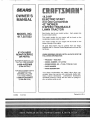
OWNER'SMANUAL
o Assembny
, Operation
Customer IResponsibnBities
o Service and Adjustments
oRepair Parts
CAUTION:
Read and follow
all safety
rules
and instructions
before
operating
this equipment.
SAFETY
Practices RULES
for Ride-On
Safe Operation
Mowers
&
IMPORTANT:
THIS COT:TiNG MACHINE ISCAPABLE
OF AMPUTATING
HANDS AND FEET AND THROWING
FAILURE TO OBSERVE THE FOLLOWING SAFETY {NSTRUCTIONS
COULD RESULT IN SERIOUS INJURY
Io
GENERAL
•
Read, understand, and follow Nil instructions in the manual
and on the machine before starting.
=
Only allow responsible adults, who are familiar with the
instructions, to op.erate the machine_
Clear =the area of objects such as rocks, toys, wire, etc,
which could be picked up and thrown by the blade.
Be sure the area is clear of other people before mowing. Stop
machine if anyone enters the area
Never carry passengers..
Do not mow in reverse unless absolutely necessary. Always
look down and behind before and while backing•
Be aware of the mower discharge direction and do not point
it at anyone. Do not operate the mower without either the
entire grass catcher or the guard in place
SIow down before turning
Never leave a running machine unattended. Always turn off
blades, set parking brake, stop engine, and remove keys
before dismounting.
Turn off blades when not mowing..
,
=
,
°
,,
°
,,
,,
=
,,
,,
°
,,
II,
OPERATION
II!.
o
o
Before and when backing, took behind and down for small
children.
-
Never carry children. They may fall off and be seriously
injured or interfere with safe machine operation
Never allow children to operate the machine.
Use extra care when approaching blind corners, shrubs,
trees, or other objects that may obscure vision
•
=
IV.
SERVICE
o
Use extra care in handling gasoline and other fuels They are
flammable and vapors are explosive,
Use only an approved container
Never remove gas cap or add fuel with the engine
running Allow engine to cool before refueling.. Do not
smoke.
Never refuel the machine indoors.
Never store the machine or fuel container inside where
there is an open flame, such as a water heater.
Never run a machine inside a closed area.
o
°
OPERATION
o
=
DO:
*
,,
o
°
Mow up and down slopes, not across.
Remove obstacles such as rocks, tree limbs, etc.
Watch for holes, ruts, o_ bumps_ Uneven terrain could
overturn the machine. Tall grass can hide obstacles.
Use slow speed° Choose a low gear so that you will not have
to stop or shift while on the slope.
Follow the manufacturer's
recommendations
for wheel
weights or counterweights to improve stability.
Use extra care with grass catchers or other attachments.
These can change the stability of the machine.
°
=
o
Keep all movement on the slopes slow and gradual Do not
make sudden changes in speed or direction._
o
Avoid starting or stopping on a slope tf tires lose traction,
disengage the blades and proceed slowly straight down the
slope
DO NOT:
Keep children out of the mowing area and under the watchful
care of another responsible adult
Be alert and turn machine off if children enter the area.
•
Slopes are a major factor related to loss-of-control and tipever
accidents, which can result in severe injury or death, All slopes
require extra caution If you cannot back up the slope or if you feel
uneasy on it, do not mow it,
,,
•
°
CHILDREN
Tragic accidents can occur if the operator is not alert to the
presence of children Children are often attracted to the machine
and the mowing activity, Never assume that children will remain
where you fast saw them
Stop engine before removing grass catcher or unclogging
chute.
Mow only in daylight or good artificial light•
Do not operate the machine while under the influence of
alcohol or drugs
Watch for traffic when operating near or crossing roadways..
Use extra care when loading or unloading the machine into
a trailer or truck.
SLOPE
OBJECTS: '..
OR DEATH.
Keep nuts and bolts especially blade attachment bolts, tight
and keep equipment in good condit on
Never tamper with safety devices..
Check their proper
operation regularly
Keep machine free of grass, leaves, or other debris build-up.
Clean oil or fuel spillage. Allow machine to cool before
storing..
Stop and inspect the equipment if you strike an object
Repair, if necessary, before restarting
Never make adjustments or repairs with the engine running.
Grass catchercomponents
are subject to wear, damage, and
deterioration, which could expose moving parts or allow
objects to be thrown. Frequently check components and
replace with manufacturer's recommended parts, when necessary..
Mower blades are sharp and can cut Wrap the blade(s) or
wear gloves, and use extra caution when servicing them.
Check brake operation frequently
Adjust and service as
required.
o
o
o
o
=
o
1
tant safety
precautions.
It .means
CAUTION!!!
Look
for this BECOME
symbol to ALERT!!!
point out imporYOUR
SAFETY
Donot turn on slopes unless necessary, and then, turn slowly
and gradually downhill, if possible..
Do not mow near drop-offs, ditches, or embankment&
The
mower could suddenly turn over if a wheel is over the edge
of a cliff or ditch, or if an edge caves ino
Do not mow on wet grass Reduced traction could cause
sliding,_
Do not try to stabilize the machine by putting your foot on the
ground°
Do not use grass catcher on steep slopes.
i ,,i,
IS INVOLVED.
i_l,
'l,I,L
CAUTION:
Always disconnect spark
plug wire and place wire where it cannot
contact spark plug in order to prevent
accidental starting when setting up,
transporting,
adjusting
or making
repairs.
2
/
':
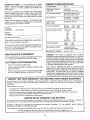
PRODUCT
CONGRATULATIONS
on your purchase of a Sears
Tractor, it has been designed, engineered and manufactured to give you the best possible dependability and
performance,
HORSEPOWER:
GASOLINE
14.0
CAPACITY
AND TYPE:
,:Should
you experience any, problem you cannot easily
remedy, please contact your nearest Sears Authorized
Service CentedDepartmenL
We have competent, welltrained technicians and the proper tools to service or repair
this tractor,
Please read and retain this manual., The instructions will
enable you to assemble and maintain your unit properly,
Always observe the "SAFETY RULES"
MODEL
NUMBER
SPECIFICATIONS
OIL CAPACiTY:
W/FILTER:
W/O FILTER:
PLUG:
RC12YC
VALVE CLEARANCE:
INTAKE:
EXHAUST:
.0015" - 0030"
0020" - .0035"
GROUND SPEED (MPH):
FORWARD:
I st
2nd
3rd
4th
5th
6th
REVERSE:
A Sears Maintenance
Agreement
uct.. Contact your nearest Sears
FRONT:
REAR:
CHARGING
3 AMPS BATTERY
5 AMPS HEADLIGHTS
SYSTEM:
Read and observe
o
Follow a regutar schedute
the safety
rule&
in maintaining,
TWO YEAR WARRANTY
30-35 FT LBS
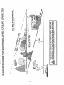
In the state of California the above is required by law
(Section 4442 of the California Public Resources Code),
Other states may have similar law& Federal laws apply on
federal lands., A spark arrester for the muffler is available
through your nearest Sears Authorized Service Center/
Department (See REPAIR PARTS section of this manual),
caring for and
using your tractor_,
Follow the instructions under "Customer Responsibilities" and "Storage" sections of this owner's manual,,
UMITED
14 PSi
12 PSi
WARNING:
This tractor is equipped with an internal
combustion engine and should not be used on or near any
unimproved forest-covered, brush-covered or grass-covered land unless the engine's exhaust system is equipped
with a spark arrester meeting applicable local or state laws
(if any),, If a spark arrester is used, it should be maintained
in effective working order by the operator.,
is available on this prodstore for details.,
CUSTOM ER RESPONSIBnLITIES
o
102
1 35
2.10
3.14
4.0O
512
1.58
TIRE PRESSURE:
BLADE BOLT TORQUE:
AGREEMENT
4..0 PINTS
35 PINTS
CHAMPION
DATEOF PURCHASE
MAgNTENANCE
.....
040")
SERIAL
NUMBER
YOU SHOULD RECORD BOTH SERIAL NUMBER AND
DATE OF PURCHASE AND KEEP IN A SAFE PLACE
FOR FUTURE REFERENCE.
REGULAR
SAE 10W-30 (above 32°F)
SAE 5W-30 (befow 32°F)
(GAP:
THE MODEL AN D SERIAL NUMBERS WILL BE FOUND
ON A PLATE UNDER THE SEAT,
_UNLEADED
OIL TYPE (API-SF/SG):
SPARK
917.,257552
5 QUARTS
,..._
ON ELECTRIC
START RIDING EQUIPMENT
For two (2) years from the date of purchase, if this riding equipment is maintained, lubricated and tuned up according to the
instructions in the owner's manual, Sears will repair or replace, free of charge, any parts found tO be defective in material or
workmanship.
This Warranty does not cover:
o
,
o
•
Expendable items which become worn during normal use, such as blades, spark plugs, air cleaners and belts,
Tire replacement or repair caused by punctures from outside objects, such as nails, thorns, stumps, or glass.
Repairs necessary because of operator abuse, negligence, improper storage or accident or the failure to maintain the
equipment according to the instructions contained in the owner's manual,,
Riding equipment used for commercial or rental purposes,
UMITED
90 DAY WARRANTY
ON BATTERY
For ninety (90) days from date of purchase, if any battery included with this riding equipment proves defective in maledal or
workmanship and our testing determines the battery will not hold a charge, Sears witf replace the battery at no charge.
WARRANTY SERVICE
CENTER!DEPARTMENT
IS AVAILABLE BY RETURNING
IN THE UNITED STATES
THE RIDING
EQUIPMENT
TO THE NEAREST
SEARS SERVICE
This Warranty gives you specific legal rights, and you may also have other rights which may vary from state to state
SEARS,
ROEBUCK
AND CO,., D/817 WA, HOFFMAN
3
ESTATES,
ILLINOIS
60179
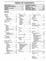
TABL
OF CONTENTS
SAFETY RULES ............................................................
2
PRODUCT SPECIFICATIONS .......................... .. ......;.,3
CUSTOMER RESPONSIBILITIES ..................... 3, 15-18
WARRANTY ..................................................................
3
TRACTOR ACCESSORIES ..........................................
5
ASSEMBLY .............................................................
7-10
OPERATION ..........................................................
11-14
MAINTENANCE SCHEDULE .....................................
15
SERVICE AND ADJUSTMENTS ........... . ............ ,.. 19-23
STORAGE ...................................................................
24
TROUBLESHOOTING ...........................................
25-26
REPAIR PARTS - TRACTOR ................................
28-45
REPAIR PARTS - ENGINE ....................................
46-51
PARTS ORDERING/SERVICE
............... BACK COVER
BNDEX
A
E
O
.........................................................
5
Electrical:
Oil:
Interlocks and Retays ...........................
22
Cold Weather Conditions .............
13,17
Adjustments:
Schematic
27
Engine ..........................................................
17
Brake ........................................................
21
Wiring Diagram .........................................
28
Sterage ................................................................
24
Carburetor .....................................................
23
Mower
Engine:
Operation .................................................
11-14
Front-To-Back ..................................
20
Air Filter .......................................................
17
Operating Mower .........................................................
I3
Side-To-Side ............................................
20
Air Screen ............................................................
18
Options:
Throttle Control Cable ......................23
Cooling Fins ...........................................................
18
Accessodes .............................................
5
Oil Change .......................................................
17
Air Filter, Engine ...................................................
17
Spark Arrester ...................................................
3,38
Oil Level ...........................................................
13
Air Screen, Engine .................................................
18
Oil Type ....................................................
13,17
Assembly ....................................................................
7-10
P
Preparation .....................................................
13
......................................................
Accessories
B
Repair Parts ...............................................
46-51
Parking Brake ...........................................
11-12
Starting ..............................................................
14
Parts Bag .....................................................................
6
Storage ..............................................................
24
Parts, Replacement/Repair
.................
28-45
Product Specifications ........................................
3
F
Battery:
Chmging .................................................
8
Cleaning ..............................................16
Installation ..........................................................
9
Filter:
R
Levels ..................................................................
8,16
Air Filter ..............................................................
17
Preparation ...................................... 8
Fuel ..........................................................
18
Repair Parts ...................................................
28-45
Starting with Weak Battery .................
22
Fuel:
Storage ...................................................................
24
S
Type ..................................................................
13
Terminals ....................................................
16
Storage .......................................................
24
Safety Rules .......................................................
2
Belt:
Fuse ..........................................................................
22
Seat ................................................................................
8
Motion Drive
Service and Adjustments ...................19-23
Removal/Replacement
................21
H
Carburetor ......................................................
23
Mower Belt(s)
Fuse .............................................................
22
Hood Removal/Installation ......................22
Removal/Replacement
.............. 21
Hood Removal/Installation
...............22
Blade:
Motion Drive Belt
L
Sharpening ............................................
16
Remova!/Replacement
..................
21
Replacement ..................................................
16
Leveling Mower Deck .....................................
20
Mower Belt(s)
Brake Adjustment ..............................................
21
Lubrication:
Remova!/Replacement
................21
Chart .....................................................15
Mower Adjustment
C
Front-to-Back ................................20
Engine ............................................,........
17
Side-to-Side ....................................
20
Carburetor Adjustment ...................................
23
Mower Removal/instaUation ........... 19
M
Controls, Tractor ........................................11
Tire Care ......................................
8,16,22
Maintenance Schedule ................................
15
Customer Responsibilities ....................
15-18
Slope
Guide
Sheet
......................................
55
Mower:
Engine:
Air Filter ........................................ t7
Spark Plug(s) ..............................................18
Adjustment, Front-to-Back ...................
20
Air Screen ................................... 18
Adjustment, Side-to-Side ............. 20
Specifications ......................................................
3
Cooling Fins ...........................................
18
Blade Replacement ................................
16
Starting the Engine ........................... 13-14
Engine Oil .....................................
13,17
Blade Sharpening ................................
16
Steering Wheel ......................................................
7,21
Fuel Filter ...............................................
18
Cutting Height ................................................
12
Stopping the Tractor ......................................
12
Spark Plug(s) ...................................
18
Installation ............................................
19
Tractor':
Storage ...............................................................
24
Operation ................................................
13
Battery .........................................................
16
Removal ......................................................
19
Blade ........................................................
16
T
Mowing Tips .....................................................
14
Lubrication Chart .................................
15
Muffler
...............................................................
18
Throttle
Control
Cable
Adjustment ........23
Maintenance Schedule ..................
15
Spark Arrester ...................................
3,38
Tire Care ..............................8,16,22
Tires ..........................................................
8,16,22
Transaxle ..............................................
17
Troubleshooting Chart .............................
25-26
Cutting Height, Mower ..................................
12
Transaxle .......................................................
17
W
4
Warranty .......................................................................
3
Wiring Diagram .....................................................
28
Wiring Schematic .......................................................
27
ACCESSORIES
AN
ATTACHMENTS
These accessories and attachments were available through most Sears retail outlets and service centers when the tractor was purchased.
Most Sears stores can order .these !terns fo[ you when. youprovide the mode.l r_umber of your tractor,
..
MAINTENANCE
ENGINE
SPARK PLUG
GAS CAN
ENGINE OIL
FUEL STABILIZER
BLADES
BELTS
,..,,%
PERFORMANCE
Sears offers a wide variety of attachments that fit your tractor_ Many of these are listed below with brief explanations of how they can help
you, This list was current at the time of publication; however, it may change in future years _ more attachments may be added, changes
may be made in these attachments, or some may no longer be available or fit your model,. Contact your nearest Sears store for the
accessories
and attachments
that are available for your tractor.
Most of these attachments do not require additional hitches or conversion kits (those that do are indicated) and are designed for easy
attaching and detaching.
SNOW BLADE forsnow removal only. 14-inch high, 48-inch wide
blade clears 42-inch path when angled left or right Raises, lowers
with side lever. Adjustable skids; replaceable, reversible scraper
bar. (Use with tire chains and wheel weights and/or rear drawbar
weight. )
SNOWTHROWER has 40-inch swath. Drum-type auger handles
powdery and wet/heavy snow, Mounts easily with simple pin
arrangement.. Discharge chute adjusts from tractor seat.. 6-inch
diameter spout discharges snow 10 to 50 feet, Lift controlled at
tractor seat. (Use with chains and wheel weights and/or rear
drawbar weight,.)
SPRAYERS use 12-vott DC electric motor that connects to the
tractor battery or other 12-volt source
Includes booms for
automatic spraying and hand held wand for spot spraying_ Wand
has adjustable spray pattern. For applying herbicides, insecticides, fungicides and liquid fertilizers.
SPREADER/SEEDERS
make seeding, fertilizing, and weed killing easy,. Broadcast spreaders are also useful for granular deicers and sand,
AERATOR promotes deep root growth for a healthy lawn. Tapered 25-inch steel spikes mounted on 10-inch diameter discs
puncture holes in soil at close intervals to let moisture soak in.
Steel weight tray for increased penetration..
BAGGER lets you collect
grass clippings and leaves for a
healthier, neater looking lawn.. Two Permanex containers hold
30-gallon plastic bags_.
BUMPER protects front end of tractor from damage,
CARTS make hauling easy,. Variety of sizes available, plus
accessories such as side panel kits, tool caddy, cart cover,
protective mat and dolly.
CORING AERATOR takes small plugs out of soil to allow moisture and nutrients to reach grass roots
36-inch swath. 24
hardened steel coring tips, 150 Ib. capacity weight tray.
EASY OIL DRAIN VALVE makes oil changes easier, faster.
FRONT NOSE ROLLER canters in front of mower deck to reduce
chances of "scalping" on uneven terrain.
GANG HITCH lets you tow 2 or3 pull-behind attachments at once,
such as sweepers, dethatchers, aerators (not for use with rollers,
carts or other heavy attachments),.
GAUGE WHEELS on both sides of the mower deck reduce
chances of "scalping" on uneven terrain. For mower decks not so
equipped.
MULCH RAKE/DETHATCHER
loosens soil and flips thatch and
matted leaves to fawn surface for easy pickup,. Twenty spring tine
teeth, Useful to prepare bare areas forseeding. Available for front
or rear mounting.
HIGH PERFORMANCE
REEL-ACTION
SPRING TINE DETHATOHER
covers 36-inch wide path and
tosses thatch into large hopper. Mounts behind tractor,
MULCHING CLOSE-OUT PLATE KIT, once installed, lets you
mulch, discharge or bag clippings (bagger optional) without
changing blades.. For models not equipped as 34n-1 Convertible
mowers.. See "MOWER" in the Repair Parts section of this
manual.
SWEEPERS let you collect grass clippings and leaves.
TILLER has 5 hp engine and 36-inch swath to prepare seed beds,
cultivate and compost garden residue Tiller has its own built-in
lilt and depth control system and does NOT require a sleeve hitch.
Fits any lawn, yard or garden tractor. Simply hook up to the tractor
drawbar and go! Optional
accessories
convert unit for
dethatching, aerating, hilling., without tools
TIRE CHAINS are heavy duty; closely spaced extra-large cross
links give smooth ride, outstanding traction.
TRACTOR CAB has heavy duty vinyl fabric over tubular steel
frame, ABS plastic top; clear plastic windshield offers 360 degree
visibility Hinged metal doors with catch. Keeps operator warm
and dry. Remove vinyl sides and windshields for use as sun
protector in summer, Optional accessories
include:
tinted/
tempered solid safety glass windshield with hand operated wiper;
12-volt amber caution light for mounting on cab top.
VACS for powerful collection of heavy grass clippings and leave&
Optional wand attachment to pick up debris in hard-to-reach
places.. VAC/CHIPPER includes a chipper-shredder,
WEIGHT BRACKET for drawbar for snow removal applications.
Uses (1) 55 lb. weight°
WHEEL WEIGHTS for rear wheels provide needed traction for
snow removal or dozing heavy materials
RAMP TOPS AND FEET let you load and unload tractor from a
pickup truck. Use with 2 x 8 or 2 x 10 lumber.
ROLLER for smoother lawn surface.
364nch wide, 184nch
diameterwater-tight
drum holds up to 390 lbs. of weight. Rounded
edges prevent harm to tdrf.. Adjustable scraper automatically
cleans drum,
5
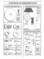
CONTENTS OF HARDWARE PACK
.....
:
..................................
: ,,,,,i,i
'':
Parts Bag contents
'
Parts packed separately in carton
shown full size
...................
i ....
i
,i
Seat
Battery acid
Metal
Scr'ews
(2)
Sheet
O
#t0-t6
(1) Locknut
x 1/2
3/8-24
Mulcher
Plate
Steering
Wheel
(1) Large Flat Washer
Steering
Boot
(1) Hex Bolt
1/2-13 x 1
(1) Shoulder Bolt
5/16-18
OwnerOs Manual
Parts Ba
Parts bag contents
not shown
_
Q
(2) Shoulder'
Bolts
(2) Washers 3/8
x 7/8 x 14 Gauge
full size
lock Nuts
(2)Center-
Wheels
(2) Gauge
(1) Lock
Washer
1/2
(1) Washer
17/32 x 1_3/16 x 12 Ga
_ok
Assemblies
__
#t
x 5/8
(2) 0Screws
(2) Lock
Washers
,
#10
[__
Steering Wheel
, Adapter
Steering
Wheel
Insert
Bushing
Steering
3/16x
3/4 x 16
(2) Washers
Gauge
_
(2) Weld
Nuts #10
<_
(2) Keys
1
2)
Hex xBolts
1/4_20
3/4
'!
f
(2) Hex
Nuts
1/4-20
_
1'
f
t' ............
(2) Washers
9/32 x 5/8 x 16
Gauge
(2) Lock
Washers
1/4
t5 Slope sheet
6
Battery Caps
and instructions
ASSEMBLY
Your new tractor has been assembled at the factory with exception of those parts left unassembled for shipping purposes,,
To ensure:safe and proper operation of your tractor all parts and hardware you =.assemblemus t be t ghtened:secur,#ly, .Use,..
the correct tools as necessary to insure proper tightnes&
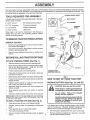
TOOLS REQUIRED
STEERING
FOR ASSEMBLY
A socket wrench set will make assembly easier. Standard
wrench sizes are listed,
(1) 5/16" wrench
3/4" Socket w/drive ratchet
(2) 7/t6" wrenches
Tire pressure gauge
(1) 1/2" wrench
Phillips Screwdriver
(1) 9/16" wrench
Utility knife
FLAT WASHER
STEERING
.....
_"--._ _
FROM CARTON
WHEEL
METAL
_
SCREW
STEERING
'
BUSHING
ADAPTER
CARTON
o
Remove all accessible loose parts and parts cartons
from carton (See page 6)
.
Cut, from top to bottom, along lines on all four corners
of carton, and lay panels flat,,
-
Check for any additional loose parts or cartons and
remove.,
STEERING
SHAFT
(ASSEMBLY
POSITION
BEFORE ROLLING TRACTOR OFF SIK_D
ATTACH
/
(' _:i:"
_v'_;_.
STEERING
UNPACK
INSERT
HEX LOCKNUT
When right or left hand is mentioned in this manual, it
means when you are in the operating position (seated
behind the steering wheel)°
TO REMOVE TRACTOR
WHEEL
STEERING
WHEEL
I
TAB
HOLE
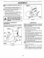
(See Fig. 1)
°
Slide the steering bushing over the steering shaft.
•
Raise steering shaft forward until screw holes in dash
line up with steering bushing., Install two (2) sheet
metai screws and tighten securely,.
TAB SLOT
STEERING
(SHIPPING
SHAFT
POSITION)
o
Position steering boot over steering shaft,.
.
Place tabs of steering boot over tab slots in dash and
push down to secure.
°
Slide steering wheel adapteronto uppersteering shaft.
o
Position front wheets of the tractor so they are pointing
straight forward
HOW TO SET UP YOUR TRACTOR
.
Position steering wheel so cross bars are horizontal
(left to right) and slide onto adapter,,
PREPARE
-
Assemble large flat washer and 3/8-24 Iocknut and
tighten securely,,
•
Snap steering wheel insert into center of steering
wheel.
FIG. I
Wash hands or clothing immediately if
accidentally in .contact with battery acid.
Do not smoke.
Fumes from
battery acid are explosive.
Raise attachment tift lever to its highest position°
°
Release parking brake by depressing clutch/brake
pedal,
Place gearshift lever in neutral (N) position,
Rol! tractor backwards off skid.
o
o
°
Remove banding holding discharge guard up against
tractor,
charged
Read the instructions included with the
battery vent caps. Always wear gloves,
clothing and goggles to protect your
hands, skin and eyes.
OFF SKID (See Fig, 8)
°
(See Figs. 2A and 2B)
CAUTION: Wear eye and face shield.
°
Remove protective plastic from tractor hood and grill,,
IMPORTANT:CHECK FOR AND REMOVE ANY STAPLES
IN SKID THAT MAY PUNCTURETIRES WHERE TRACTOR
IS TO ROLL OFF SKID,.
TO ROLL TRACTOR
BA'N'ERY
Your tractor has a battery charging system which is sufficient for normal use. However, periodic charging of the
battery with an automotive charger will extend its life,
7
°
See instructions packed with vent caps in parts bag.
o
Remove cardboard packing from seat pan, r_ ise seat
pan and open battery box door..
ASSEM
LY
.
Remove battery from tractor to fill with acid and charge.
iNSTALL
°
Fill battery with acid° Fill each ceil until it reaches the
bottom of the vent wells,, Do not overfill
Adjust seat before tightening adjustment bolt.
°
Allow battery to stand and settle for at least thirbj
minute& After standing, check the battery cell acid
level If below the vent wells, add more acid until the
correct level is reached.
While battery is standing (after'adding
acid) and later, while
battery is being charged, continue with assembly of tractor',
IMPORTANT:
TO MAXIMIZE
THE LIFE OF YOUR
BATTERY,
IT IS NECESSARY
THAT THE BATTERY
BE
CHARGED
BEFORE
USE.
FAILURE
TO CHARGE
BATTERY
CAN RESULT
IN A SHORTENED
BATTERY
LIFE,
*
Charge battery at a rate of 6 amperes for 1 hour. Use
a 12 volt battery charger_ Observe all safety precautions required for battery charging,
o
Check the acid level after the battery is charged. If the
acid has fallen below the correct level, add distilled or
iron free water°
o
Check battery case for leakage to make sure that no
damage has occurred in handling°
.
Dispose of excess battery acid. Neutralize acid for
disposal by adding it to two gallons of water in a five
gallon plastic container.. Stir with a wooden or plastic
paddle while adding baking soda until the addition of
more soda causes no more foaming.
o
°
Remove cardboard packing on seat pan.
.
Place seat on seat pan and assemble shoulder bolt.
°
Assemble adjustment bolt, lock washer and flat washer
loosely. Do not tighten,.
.
Tighten shoulder bolt securely
=
Lower seat into operating position and sit on seat.
°
Slide seat until a comfortable position is reached which
allows you to press clutch/brake pedal all the way
down.
°
Get off seat without moving its adjusted position,,
o
Raise seat and tighten adjustment bolt securely,,
SEAT
SEAT PAN
Install the vent caps to cover the vent wells° Wash the
top of the battery with water' to remove any acid, then
wipe dry.
°
SEAT (See Fig. 3)
SHOULDER
BOLT
FLAT WASHER
Follow instructions on how to install battery,,
ADJUSTMENT
BOLT
.OCK WASHER
FIG. 3
SEAT PAN
CHECK TiRE
BATTERY
BOX DOOR
PRESSURE
The tires on your' tractor were overinflated at the factory for
shipping purposes,. Correct tire pressure is important for
best cutting performance_
=
Reduce tire pressure to PSI shown in "PRODUCT
SPECIFICATIONS" on page 3 of this manual,
CHECK
For best cutting results, mower housing should be properly
leveled.
See "TO LEVEL MOWER HOUSING" in the
Service and Adjustments section of this manual°
FIG 2A
CHECK
BELTS
VENT CAP
CUT AWAY VIEW
DECK LEVELNESS
WELL
FOR
PROPER
POSiTiON
OF
ALL
See the figures that are shown for replacing motion and
mower blade drive belts in the Service and Adjustments
section of this manual. Verify that the belts are routed
correctly.
BATTERY
ACID
LEVEL
CHECK
BRAKE
SYSTEM
After you learn how to operate your tractor, check to see
that the brake is'properly adjusted, See "TO ADJUST
BRAKE" in the Service and Adjustments section of this
manual.
FIG. 2B
8
INSTALL
..................
- -
BATTERY
......
,
(See Figs. 4 and 5)
.... ,
=,__
_:.,
,,,:""
'4,:
CAUTION: Do not short battery terminals. Before installing battery, remove
metal bracelets, wristwatch bands,
rings, etc.
Positive terminal must be connected
first to prevent sparking from accidental grounding.
o
Lift seat to raised position..
=
Open battery box doer..
•
Be sure battery drain tube is attached to battery box.
•
Lower battery into battery box with battery terminals
toward front of tractor.
°
First connect RED battery cable to positive (+) terminal
with hex bolt, flat washer, lock washer and hex nut as
shown. Tighten securely.
°
Connect BLACK grounding cable to negative (-) terminal with remaining hex bolt, flat washer, lock washer
and hex nut. Tighten securely..
o
Close battery box door.
BATTERY
BOX DOOR
;
FIG. 5
ASSEMBLE
Open battery box door for:
°
inspection
VENT CAPS
i
for secure connections
GAUGE
WHEELS
TO
MOWER
DECK (See Fig. 6)
(to tighten hard-
ware).
Assemble gauge wheels with tractor on a flat level surface°
°
Inspection for corrosion.
,
Testing battery,
o
Jumping (if required).,
•
Periodic charging.,
o
Adjust mower to desired cutting height (See "TO ADJUST MOWER CUTTING HEIGHT" in the Operation
section of this manual),
With mower in desired height of cut .position, gauge
wheels should be assembled so they are slightly off the
groun& Install gauge wheel in appropriate hole with
shoulder bolt, 3/8 washer and 3/8-16 focknut and
tighten securely..
BATTERY
BOX DOOR
=
Repeat for opposite side installing gauge wheel in
same adjustment hole..
GAUGE WHEEL
MOUNTING
BRACKET
\,
\
_'/___
(NEGATIVE)
BLACK CABLE
(POSITIVE)
RED
LOCK
WASHER
HEX
FLAT
HEX
BOLT
FIG. 6
POSITIVE (+) TERMINAL
NEGATIVE
(-) TERMINAL
FIG. 4
9
LY
iNSTALL
7B)
•
NIULCHER
PLATE
(See Figs.7 A & ......
......
DEFLECTOR
.... SHIELD
......
Install two latch hooks to mulcher plate using screw,
washer', took washer, and weld nut as shown°
NOTE: Pre-assemble weld nut to latch hook by inserting
weld nut from the top with hook pointing down.
•
Tighten hardware securely.
o
Raise and hold deflector shield in upright position.
o
Place front of mutcher plate over front of mower' deck
opening and slide into place, as shown_
Hook front latch into hole on front of mower deck°
°
Hook rear latch into hole on back of mower deck.
CAUTION:
LATCH
HOOKS
Do not remove discharge
guard when
attachingRaise
muicher
from mower.
and plate
hold
and allow it to rest on plate while in
operation.
TO CONVERT
DISCHARGING
TO BAGGING
FIG. 7B
CHECKLIST
OR
BEFORE YOU OPERATE AND ENJOY YOUR NEW
TRACTOR, WE WISH TO ASSURE THAT YOU RECEIVE
THE BEST PERFORMANCEAND
SATISFACTION FROM
THIS QUALITY PRODUCT
Simply remove mulcher plate and store in a safe place.
Your mower is now ready for discharging or' installation of
c _tional grass catcher' accessory,
LOCK
WASHER
WELD.
NUT
PLEASE REVIEW THE FOLLOWING
HOOK POINTS
DOWN
WELD NUT
FROM
#"
All assembly instructions have been completed..
#"
No remaining loose parts in carton.
J
Battery" is properly prepared and charged°
1 hour at 6 amps),.
v"
Seat is adjusted comfortably
#"
All tires are properly inflated. (For' shipping purposes,
the tires were ovednflated at the factory).
,/
Be sure mower deck is properly leveled side-to-side/
front-to-rear for best cutting results. (Tires must be
properly inflated for leveting)o
,/
Check mower and drive beffs. Be sure they are routed
properly around pulleys and inside all belt keepers.
J"
Check wiring. See that all connections are still secure
and wires are properfy clamped.
-'_
HOOK
HOOK
LOCK
WASHER
WELD
NUT
WASHER
CHECKLIST:
(Minimum
and tightened securely.
WHILELEARNING HOWTO USE YOUR TRACTOR, PAY
EXTRA A TTENTtON TO THE FOLLOWING IMPORTANT
ITEMS.:
MULCHER
PLATE
FIG. 7A
v"
Engine oil is at proper level
#"
Fuel tank is filled with fresh, clean, regular unleaded
gasoline.
Become familiar with all controls - their location and
function. Operate them before you start the engine.
,/
J
10
Be sure brake system is in safe operating condition_
OPERATmON
.........
._
• ...........
, ,
,,
• ...........
,,,,
.........................
....
KNOWYOURTRACTOR
READ THIS OWNER'S
NANUAL
AND SAFETY
RULES
BEFORE
OPERATING
Compare the illustrations with your tractor to familiarize yourself with the location of various controls
this manual for future reference,,
ATTACHMENT
CLUTCH LEVER
YOUR TRACTOR.
and adjustments,
Save
IGNITION SWITCH
THROTTLE/CHOKE
CONTROL
ATTACHMENT
LIFT LEVER
CLUTCHIBRAKE
PEDAL
PARKING
LEVER
BRAKE
HEIGHT
ADJUSTMENT
KNOB
GEARSHIFT
LEVER
FIG. 8
Our tractors conform to the safety standards of _he American National Standards Institute.
ATTACHMENT CLUTCH LEVER* Used to engage mower
blades or other attachments mounted to your tractor_
GEARSHIFT
the tractor.
LEVER - Selects the speed and direction of
ATTACHMENT LIFT LEVER - Used to raise and lower
mower deck or other attachments mounted to your tractor
IGNITION SWITCH - Used to start and stop the engine,
PARKING BRAKE LEVER - Locks clutch/brake pedat into
the brake pos{tion,
CLUTCH/BRAKE
PEDAL - Used for declutching and
braking the tractor and starting the engine,,
HEIGHT ADJUSTMENT KNOB- Used to adjust the mower
height,
THROTTLE/CHOKE
CONTROL - Used for starting and
controling engine speed°
LIFT LEVER PLUNGER - Used to release attachment lift
lever when changing its position°
LIGHT SWITCH - Turns the headlights on and off,,
'11
OPERATION
....
ii!,,
!,
:.......................
,-,...............
:i x:,;;;¸
......................
i:iiii i_ii::ii¸
i¸
ii:iii...........
::_:
:i::i
::::
..................................................
The operation of any tractor can result in foreign qbjects thrown into the eyes, wh!ch can
result in severe eye damage. Always wear safety glasses or eye shields while operating
your tractor or performing any adjustments or repairs. We recommend a wide vision safety
mask over the spectacles or standard safety glasses.
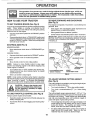
TO MOVE FORWARD
(See Fig. 9)
HOW TO USE YOUR TRACTOR
TO SET PARKgNG
BRAKE
(See Fig. 9)
The direction and speed of movement
gearshift lever.
Your tractor is equipped with an operator presence sensing
switch. When engine is running, any attempt by the
operator to leave the seat without first setting the parking
brake will shut off the engine.
o
Depress clutch/brake
and hold_
pedal into full "BRAKE" position
o
Start tractor with clutch/brake pedal depressed
gearshift lever in neutral (NI) position,
°
Move gearshift lever' to desired
and
position°
ATTACHMENT CLUTCH
LEVER "ENGAGED"
POSITION
"DISENGAGED"
(SEE RG. 9)
MOWER BLADES o
is controlled by the
,
Slowly release clutch/brake pedal to start movement.,
IMPORTANT: BRING TRACTOR TO A COMPLETE STOP
BEFORE SHIFTING OR CHANGING GEARS. FAILURE
TO DO SO WILL SHORTEN THE USEFUL LIFE OF YOUR
TRANSAXLE..
Place parking brake lever' in "ENGAGED" position and
release pressure from clutch/brake pedal. Pedal should
remain in "BRAKE" position., Make sure parking brake
will hold tractor secure.,
STOPPING
AND BACKWARD
Move attachment clutch lever to "DISENGAGED"
sition.,
po-
GROUND DRIVE°
Depress clutch/brake
°
Move gearshift
ENGINE *
o
pedal into full "BRAKE" position..
lever to neutral (N) position°
Move throttle control to slow (,_)
position.,
NOTE;
Failure to move throttle control to slow (,_)
position and allowing engine to idle before stopping may
cause engine to "backfire",
,
°
Turn ignition key to "OFF" position and remove key.
Always remove key when leaving tractor to prevent
unauthorized use..
CLUTCH/BRAKE PEDAL
"DRIVE" POSITION
HEIGHT
ADJUSTMENT'
KNOB
FIG. 9
Never use choke to stop engine.
NOTE; Under certain conditions when tractor is standing
idle with the engine running, hot engine exhaust gases may
cause "browning" of grass. To eliminate this possibility,
always stop engine when stopping tractor on grass areas,
TO ADJUST
MOWER
CUTTING
HEIGHT
(See Fig. 9)
The cutting height iscontrolled by turuing the height adjustrnent knob in desired direction
TO USE THROTTLE
CONTROL
Always operate engine at full throttle°
Operating engine at Iess than full throttle reduces the
battery charging rate.
=
Full throttle offers the best bagging and mower performance.
Turn knob clockwise (1_)
to raise cutting heighL
°
Turn knob counterclocleMse (1_-'_)to lower cutting
height.
The cutting height range is approximately 1-1/2" to 4'L The
heights are measured from the ground to the blade tip with
the engine not r'unning. These heights are approximate
and may vary depending upon soil conditions, height of
grass and types of grass being mowed.
(See Fig. 9)
•
o
12
•
The average lawn should be cut to approximately 2-1/2
inches during the cool season and to over 3 inches
dunng hot months. For healthier and better looking
lawns, mow often and after moderate growth.
°
For best cutting performance, grass over 6 inches in
height should be mowed twice. Make the first cut
relatively high; the second to desired height.
OPERATION
TO OPERATE
MOWER
(See Fig.
TO TRANSPORT
10)
Your tractor is equipped with an operator presence sensing
switch. Any attempt by the operator to leave the seat with
the engine running and the attachment clutch engaged will
shut off the engine.
=
Raise attachment lift to highest position with attachment lift control.
o
When pushing ortowing your tractor, be sure gearshift
lever is in neutral (N) position.
o
°
Select desired height of cut
Lower mower with attachment
.
Do not push or tow tractor at more than five (5) MPH.
°
Start mower blades by engaging attachment
control.
o
TO STOP MOWER BLADES - disengage attachment
clutch control°
"
r,,,
A
' .....
lift control
I' 'l'"',',l,UI,,
NOTE: To protect hood from damage when transporting
your tractor on a truck or a trailer, be sure hood is closed and
secured to tractor, Use an appropriate means oftying hood
to tractor (rope, cord, etc.)..
clutch
BEFORE
..........
CHECK
without either the entire grass catcher,
on
mowers Do
so not
equipped,
disCAUTION:
operate or
thethe
mower
charge guard in place.
STARTLING THE ENGBNE
ENGINE
OIL LEVEL
(See Fig. 17)
o
The engine in your tractor has been shipped, from the
factory, already filled with summer weight oil.
=
Check engine oil with tractor on level ground.
=
Unthread and remove oil fill cap/dipstick; wipe oil off°
Reinsert the dipstick into the tube and rest oil fill cap on
the tube, Do not thread the cap onto the tube. Remove
and read oil level,. If necessary, add oil until "FULL"
mark on dipstick is reached. Do not overfill°
=
For cold weather operation you should change oil for
easier starting (See "OIL VISCOSITY CHART" in the
Customer Responsibilities section of this manual).
•
To change engine oil, see the Customer Responsibilities section in this manual
ADD GASOLINE
=
Fill fuel tank,, Use fresh, clean, regular unleaded
gasoline. (Use of leaded gasoline will increase carbon
and lead oxide deposits and reduce valve life),
IMPORTANT; WHEN OPERATING IN TEMPERATURES
BELOW 32°F(0°C), USE FRESH, CLEAN WINTER GRADE
GASOLINE TO HELP INSURE GOOD COLD WEATHER
STARTING.
FIG. 10
TO OPERATE
WARNING:
Experience indicates that alcohol blended
fuels (called gasohol or using ethanol or methanol) can
attract moisture which leads to separation and formation of
acids during storage° Acidic gas can damage the fuel
system of an engine while in storage° To avoid engine
problems, the fuel system should be emptied before storage of 30 days or longer. Drain the gas tank, start the
engine and let it run until the fuel lines and carburetor are
empty. Use fresh fuel next season, See Storage Instructions for additional information,
Never use engine or
carburetor cleaner products in the fuel tank or permanent
damage may occur,
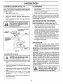
ON HILLS
CAUTION:
Do not drive up or down
hills with slopes greater than 15 ° and
do not drive across any Slope.
°
Choose the slowest speed before starting up or down
hills.
°
Avoid stopping or changing speed on hills
°
If slowing is necessary, move throttle control lever to
slower position°
°
If stopping is absolutely necessary, push clutch/brake
pedal quickly to brake position and engage parking
brake.
•
Move gearshift lever to 1st gear. Be sure you have
aItowed room for tractor to roll slightly as you restart
movement,
o
To restart movement, slowly release parking brake and
clutch/brake pedal.
°
Make all turns slowly
13
OPERAT|O
TO START
ENGINE
(See Fig. 9)
When st'a_tIff_j6r,gine for' the first time or if engine has run
out of fuel, it will take extra cranking time to move fuel from
the tank to the engine
•
Depress clutch/brake pedal and set parking brake.
o
Place gearshift lever in neutrai (N) position°
°
Move attachment clutch to "DISENGAGED"
°
Move throttle control lever to choke (N) position for
cold engine start. For warm engine start, move throttle
control to fast (,_) position_
°
Insert key into ignition and turn keyclockwiseto"START"
position and release key as soon as engine starts. Do
not run starter continuously for- more than fifteen
seconds per minute. If engine does not start after
several attempts, move throttle control to fast (,_)
position, wait a few minutes and try again..
t
C .....
position.
-
When engine starts, move throttle control to desired
position..
=
Allow engine to warm up for a few minutes before
engaging drive or' attachments.
,J
FIG. 11
MULCHING
MOWING
TiPS
IMPORTANT:
FOR BEST PERFORMANCE,
KEEP
MOWER HOUSING FREE OF BUILT-UP GRASS AND
TRASH. CLEAN AFTER EACH USE.
The special mulching blade will recut the grass clippings many times and reduce then] in size so that as
they fall onto the lawn they will disperse into the grass
and not be noticed Also, the mulched grass will
biodegrade quickly to provide nutrients for the lawn.
Always mulch with your highest engine (blade) speed
as this will provide the best recutting action of the
blades_
NOTE: If at a high altitude (above 3000 feet) or in cold
temperatures (below 32°F), the carburetor fuel mixture
may need to be adjusted for best engine performance_ See
"TO ADJUST CARBURETOR" in the Service and Adjustments section of this manual..
o
Avoid cutting your lawn when it is wet. Wet grass tends
to form clumps and interferes with the mulching action.
The best time to mow your lawn is the early afternoon=
At this time the grass has dried and the newly cut area
will not be exposed to the direct sun°
MOWUNGTIPS
°
Tire chains cannot be used when the mower housing is
attached to tractor.
=
o
Mower should be properly leveled for best mowing
performance° See "TO LEVEL MOWER HOUSING" in
the Service and Adjustments section of this manual
The left hand side of mower should be used for trimming.
For best results, adjust the mowercutting height so that
the mower cuts off only the top one-third of the grass
blades (See Fig. 12)_ For' extremely heavy mulching,
reduce your width of cut on each pass and mow slowly.
°
Certain types of grass and grass conditions may require that an area be mulched a second time to completely hide the clippings. When doing a second cut,
mew across or perpend!cular to the first cut path°
o
Change your cutting pattern from week to week. Mow
north to south one week then change to east to west the
next week. This will help prevent matting and graining
of the lawn.
o
=
Drive so that clippings are discharged onto the area
that has been cut. Have the cut area to the right of the
machine_ This will result in a more even distribution of
clippings and more uniform cutting_
°
When mowing large areas, start by turning tb the right
so that clippings will discharge away from shrubs,
fences, driveways, etc, After one ortwo rounds, mow
in the opposite direction making left hand turns until
finished (See Fig. 11).
o
If grass is extremely tail, it should be mowed twice to
reduce toad and possible fire hazard from dried clippings. Make first cut relatively high; the second to the
desired heighL
°
Do not mow grass when it is wet.. Wet grass will plug
mower and leave undesirable clumps. Allow grass to
dry before mowing.
o
Always operate engine at full throttle when mowing to
assure better mowing performance and proper discharge of material Regulate ground speed by selecting a low enough gear to give the mower cutting
performance as well as the quality of cut desired.
°
When operating attachments, select a ground speed
that will suit the terrain and give best performance of
the attachment being used..
MAX 1/3
FIG. 12
14
ESPONS!B UTIES
CUSTO
L
...............
,,
,,: ....
i..........
............ ,.,
i,,
_,,_ .....
:: ::. : .: .....
, ,,,,,
................
AS YOU COMPLETE
..............
check
..............
B_ke"Operatio'n
,,,I,
.............
"'_
Check Tire Pressure
T
_
_
Check' for Loose Fasteners ......
R
i .......
!
_#'
_
...........
I
.......
..........
Sharpen!Replace
Mower Btades ...............
'Lubrication
Chart
.............
_............
C
,
:'. _'7
_4
_
I
..............
Check Battery Level/Recharge
0
Clean Battery and Terminals
6_
a
Check Transaxle
6/
,,
Be.(s)
Ten i0' .....................
......
_
....
".....
....
, ...
............... , .........
...........
•.
.._
.................
[
Replace'"0i!
"siean
E
Fiite;"ilf
Engine coo]ing
.;; .....
.......
6/
...................
,,
::
,.....................
_#2
equipp'ed)
............
...............
_
....
i" .......................
......
.
_,2
Fins
Replace Spark Plug
___
....'
6##=
" ....................
6## ' _#' ..........
_/2
....
Replace Fuel Filter
6#4
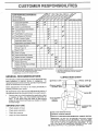
Change more often when operating under a heavy toad er in high ambient temperatures
Service more often when operating in dirty er dusty conditions
If equipped with oil fiiler, change oil every 50 hours
Replace blades more oflen when mowing in sandy soil
GENERAL
-_
t_._ii ....
RePIace Air Fiiier Paper Cartridge
12 34-
!:::::!
.......
Inspect Muffler/Spark'Arresier
N
.........
6/2
N _c'eanAirScreen
G
:
6#4'
Ctean Air Filter
E
.....................
_#'5
.................
Eng'i'n'e0,,
6##
.....................
Adjust Motion Drive Belt(s) Tension
change
...............
_
Cooling
Check Engine Oil Level
_
.....
.
T
'.
5 - If equipped 'Mth adjustable system
6- Not required if equipped wilh mainlenanoe-lree battery
7 - Tighten tronl axle pivm bolt 1o 35 tt 4bs maximum,
De net overlighlen
RECOMMENDATUONS
The warranty on this tractor does not cover items that have
been subjected to operator abuse or negligence.
To
receive full value from the warranty, operator must maintain
tractor as instructed in this manual
LUBRICATION
(_)SPINDLE
CHART
ZERK_
SPINDLE
®
®
BEARING
Some adjustments will need to be made periodically to
properly maintain your tractor.
ZERK
BEARING
Al! adjustments in the Service and Adjustments section of
this manual should be checked at least once each season.
Once a year you should replace the spark plug, clean
or replace air filter, and check blades and belts for
wear_ A new spark plug and clean air filter assure
proper air-fuel mixture and help your engine run better
and last longer.
BEFORE
EACH
Check engine oil level
o
Check brake operation,
°
•
Check tire pressure
Check for toose fasteners,
ZERK
®
G
CLUTCH
PIVOT(S)
USE
•
ZERK
GEARSHIFT(_)
PIVOTS
(_SAE
30 OR 10W30 MOTOR OIL
(_GENERAL
PURPOSE GREASE
® REFER TO CUSTOMER
15
RESPONSIBILITIES
"ENGINE"
SECTION
IMPORTANT;
DO NOT OIL OR GREASE
THE PIVOT POINTS
WHICH HAVE SPECfAL NYLON BEARINGS..
VISCOUS
LUBRiCANTS WILL ATTRACT
DUST AND DIRT THAT WILL SHORTEN
THE LIFE OF THE SELF-LUBRICATING
BEARINGS.
IF YOU
FEEL THEY MUST BE LUBRICATED,
USE ONLY A DRY, POWDERED GRAPHtTE
TYPE LUBRICANT
SPARINGLY.
PO
IL
ES
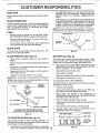
To check blade balance, you will need a 5/8" diameter
steel bolt, pin, ora cone batancer. (When using a cone
balancer, follow the instructions supplied with bat-
o
anGer,)
o
BRAKE OPERATION
If tractor requires more than six (6) feet stopping distance
at high speed in highest gear, then brake must be adjusted.
(See %'O ADJUST BRAKE" in the Service and Adjustments section of this manual).
Slide blade on to an unthreaded portion of the steel bolt
or pin and hold the bolt or pin parallel with the ground.
If blade is balanced, it should remain in a horizontal
position. If either end of the blade moves downward,
sharpen the heavy end until the blade is balanced.
NOTE: Do not use a nail for' balancing blade. The lobes of
the center hole may appear to be centered, but are not.
TIRES
•
Maintain proper air pressure in ati tires (See "PRODUCT SPECIFICATIONS"
on page 3 of this manual).
•
Keep tires free of gasoline, oil, or insect control chemicals which can harm rubber
•
Avoid stumps, stones, deep ruts, sharp objects and
other hazards that may cause tire damage
BLADE
CARE
For best results mower blades must be kept sharp_ Replace bent or damaged blades.
BLADE
REMOVAL
FIG. 14
(See Fig. 13)
BATTERY (See Fig. 15)
•
Raise mower to highest position to allow access to
blades_
•
Remove hex bolt, lock washer and fiat washer securing
blade
°
Install new or resharpened blade with trailing edge up
towards deck as shown.
o
Reassemble hex bolt, lock washer and flat washer in
exact order as shown_
Your tractor has a battery charging system which is sufficient for normal use_ However, periodic charging of the
battery with an automotive charger will extend its life
=
Acid solution level in each battery celt should be even
with bottoms of vent wells_ Add only distilled or iron free
water' if necessary. Do not overfill.
°
Keep battery and terminals clean.
o
Keep battery bolts tight.
o Tighten bolt securely (30-35 Ft. Lbs. torque).
IMPORTANT: BLADE BOLT IS GRADE 8 HEATTREATED
=
Keep vent caps tight and srnaU vent hotes in caps open.
°
Recharge at 6 amperes for t hour,
NOTE: We do not recomrnend sharpening blade - but ifyou
do, be sure the blade is balanced°
TO CLEAN BATTERY AND TERMINALS
Corrosion and dirt on the battery and terminals can cause
the battery to "leak" power_
MANDREL
ASSEMBLY
BLADE
*A GRADE 8 HEAT TREATED BOLT CAN BE
IDENTIFIED BY SIX LINES ON THE BOLT HEAD.
=
Remove terminal guard_
o
Disconnect BLACK battery cable first then RED bah
tery cable and remove battery from tractor°
o
Wash battery with solution of four tablespoons of
baking soda to one gallon of water_ Be careful not to get
the soda solution into the cells.
°
Rinse the battery with plain water and dry
o
Clean terminals and battery cable ends with wire brush
until brighL
.
Coat terminals with grease or petroleum jelly,
°
Reinstall battery (See "INSTALL BATTERY"
Assembly section of this manual)°
CUT AWAY VIEW
FIG. 13
[
TO SHARPEN
BLADE
VENTCAP
!
VENT WELL
(See Fig. 14)
BATTERY
CELL ACID
LEVEL
Care should be taken to keep the blade balanced_ An
unbalanced blade will cause excessive vibration and eventual damage to mower and engine.
°
/
in the
The blade can be sharpened with a rite or on a grinding
wheel Do not attempt to sharpen whiie on the mower.
16
FIG. 15
RESPONSJ
CVSTO
V-BELTS
TRANSAXLE
Your engine will not run properly using, a dirty air filter;
Clean the foam pre-cleaner after every 25 hours of operation or every season, Service paper cartridge every 100
hours of operation or eve ry season, whichever occurs firsL
Service air cleaner more often under dusty conditions.
.
Remove knob and cover.
COOLING
Keep transaxle free from build-up of dirt and chaff which
can restrict cooling,
Remove wing nut and air cleaner from base°
TO SERVICE PRE-CLEANER
o
ENGUNE
Slide foam pre-cleaner off cartridge
LUBRICATION
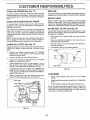
Only use high quality detergent oil rated with API service
classification SF or SG. Select the oil's SAE viscosity grade
according to your expected operating temperature°
SAE VISCOSITY
30"
O"
-20 _
TEMPERATURE
-10"
RANGE
32"
0_
40 _
ANTICIPATED
605
B0°
1'0_
BEFORE
Wash it inliquid detergent and water,,
o
Squeeze it dry in a clean cloth,
o
Saturate it in engine oil,, Wrap it in clean, absorbent
cloth and squeeze to remove excess oil
°
1,
-20 °
o
TO SERVICE CARTRIDGE
GRADES
1
.30"
ES
AIR FILTER (See Fig. 17)
........Check V-betts for deterioration and wear, after 100 hours of
operation and replace if necessary, The belts are not
adjustable, Replace belts if they begin to slip from wean
°F
°C
tL
20 b
NEXT
,
30 _
100°
40"
Gently tap the flat side of the paper cartridge to dislodge dirt_ Do not wash the paper cartridge or use
pressurized air, as this will damage the cartridge,,
Replace a dirty, bent, or damaged cartridge.
Reinstall the pre-cfeaner (cleaned and oiled) over the
paper cartridge,
OIL CHANGE
Reassemble air cleaner, wing nut, cover and tighten
knob securely_
FIG. 16
NOTE: Although multi-viscosity oils (5W30, 10W30 etc.)
improve starting in cold weather, these mufti-viscosity oils
will result in increased oil consumption when used above
32°F. Check your engine oil level more frequently to avoid
possible engine damage from running low on oito
COVER KNOB
AIR CLEANER
COVER
WING NUT
RUBBER
GROMMET
FOAM
PRE-CLEANER
Change the oil after the first two hours of operation and
every 50 hours thereafter or at least once a year if the
tractor is not used for 50 hours in one year,
Check the crankcase oil level before starting the engine
and after each eight (8) hours of operation. Tighten oil fill
cap/dipstick securely each time you check the oil level°
TO CHANGE ENGINE OIL (See Figso16 & 17)
AIR CI.EANER
BASE
Determine temperature range expected before oil change.
All oil must meet API service classification SF or SG_
•
Be sure tractor is on level surface,.
.
Oil wilt drain more freely when warm,
Catch oil in a suitable container.
o
Remove oil fill cap/dipstick, Be careful not to allow dirt
to enter the engine when changing oil,
o
Remove drain plug,,
°
After oil has drained completely, replace oil drain plug
and tighten securely
°
Refill engine with oil through oil fill dipstick tube. Pour
slowly. Do not overfill,, For approximate capacity see
"PRODUCT SPECIFICATIONS"
on page 3 of this
manual.
PAPER CARTRIDGE
OIL FILL
CAP/DIPSTICK
AIR
OIL DRAIN
PLUG
FIG. 17
Use gauge on oil fill cap/dipstick for checking level.,
Insert dipstick into the tube and rest the oil fill cap on the
tube. Do not thread the cap onto the tube when taking
reading. Keep oil at "FULL" line on dipstick. Tighten
cap onto the tube securely when finished.
'I7
J
¢USTO
RESPONSJ
LITIE
i
CLEAN
A!R SCREEN
MUFFLER
(See Fig. 17)
Inspect and replace corroded muffler and spark arrester (if
equipped) as it could create a fire hazard and/or damage.
Air' screen must be kept free of dirt and chaff to prevent
engine damage from overheating_ Clean with a wire brush
or compressed air to remove dirt and stubborn dried gum
fibers°
CLEAN
AIR INTAKE/COOLING
SPARK PLUGS
Replace spark plugs at the beginning of each mowing
season or after every 100 hours of operation, whichever'
occurs first. Spark plug type and gap setting are shown in
"PRODUCT SPECIFICATIONS" on page 3 of this manual
AREAS
To insure proper cooling, make sure the grass screen,
cooling fins, and other external surfaces of the engine are
kept clean at all times.
IN-LINE
FUEL FILTER
(See Fig. 19)
Every 100 hours of operation (more often under extremely
dusty, dirty conditions), remove the blower' housing and
other cooling shrouds. Clean the cooling fins and external
surfaces as necessary. Make sure the cooling shrouds are
reinstalled.
The fuel filter should be replaced once each season° If fuel
filter becomes clogged, obstructing fuel flow to carburetor,
replacement is required.
°
NOTE: Operating the engine with a btocked grass screen,
dirty or plugged cooling fins, and/or cooling shrouds removed will cause engine damage due to overheating°
With engine coot, remove filter and plug fuel line
sections.
°
Place new fuel filter in position in fuel line with arrow
pointing towards carburetor.
Be sure there are no fuel line leaks and clamps are
properly positioned.
ENGINE
OIL FILTER
=
(See Fig. 18)
Replace the engine oil filter every season or every other oil
change if the tractor is used more than 100 hours in one
year.
= Drain oil from engine crankcase (See "TO CHANGE
ENGINE OIL" in this section of this manual, through
step remove drain plug).
=
Remove oil filter and wipe off filter adapter_
=
Apply a thin coating of new engine oil to the rubber
gasket on replacement oil filter..
o
Install replacement oil filter on filter adapter. Turn oil
filter clockwise until rubber gasket contacts the _ter
adapter, then tighten filter an additional 1/2 turn_
Fil! crankcase with new oil (See ''TO CHANGE ENGINE OIL" in this section of this manual). For approximate capacity see "PRODUCT SPECIFICATIONS" on
page 3 of this manual.
o
o
o
Immediately wipe up any spilled gasoline.
CLAMP
CLAMP
FUEL FILTER
FIG. 19
CLEANING
Start the engine and check for oi! teaks. Correct any
leaks before placing engine into full operation.
OIL FILTER
=
Clean .engine, batte_,
matter'.
seat, finish, etc° of all foreign
=
Keep finished surfaces and wheels free of all gasoline,
oil, etc_
=
Protect painted surfaces with automotive type wax_
We do not recommend using a garden hose to clean your
tractor unless the electrical system, muffler, air filter and
carburetor are covered to keep water ouL Water in engine
can result in a shortened engine _ife.
FIG. 18
18
_ .........
1
:
,,
,.,
:::...:: ....
r_,:.....
,''1 '
.
;_._,
_
''
::"::................
;_;,;;
.........
:
......
" --
,_;_;,_;,_
$ERVUCE ANDADJUSTMENTS
CAUTION:
=
•
°
o
o
°
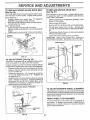
BEFORE PERFORMING ANY SERVICE OR ADJUSTMENTS:
Depress
clutch/brake
fully(N)and
set pa'rking brake, ........
.....
Place gearshift
lever inpeda|
neutral
positron.
Place attachment clutch in "DISENGAGED"
position.
Turn ignition key "OFF" and remove key.
Make sure the blades and all moving parts have completely stopped.
Disconnect spark plug wire from spark plug and place wire where it cannot come in contact with
plug.
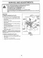
TRACTOR
TO REMOVE
MOWER
(See Fig. 20)
Mower will be easier to remove from the right side of tractor_
o
Place attachment clutch in "DISENGAGED"
o
Move attachment lift lever forward to lower mower to its
towest position,
°
Roll belt off engine puliey_
°
Disconnect clutch rod from clutch lever by removing
retainer spring,.
.
Disconnect anti-sway bar from chassis bracket by
removing retainer spnng_
°
Disconnect suspension arms from rear deck brackets
by removing retainer springs.
=
Disconnect front links from deck by removing retainer
springs°
Raise lift lever to raise suspension arms. Slide mower
out from under tractor.
°
CLUTCH
position.
SUSPENSION
ARMS
MOWER
RETAINER
SPRING
ANTI-SWAY
Raise attachment lift lever to its highest position°
°
Slide mower undertractorwith
side of tractor_
°
Lower lift lever to its lowest position..
=
Install mower in reverse order of removal instructions_.
BAR
RETAINER
SPRINGS
(BOTH SIDES)
(See Fig. 20)
o
ENGINE
PULLEY
SPRINGS
(BOTH SIDES
IMPORTANT:
IF AN ATTACHMENT OTHER THAN THE
MOWER iS TO BE MOUNTED TO THE TRACTOR, THE
R.H. AND L°H. SUSPENSION ARMS MUST BE REMOVED
FROM TRACTOR
TO INSTALL
SPRING
FIG. 20
discharge guard to right
19
ERVJCE AND ADJUSTMENTS
TO LEVEL MOWER HOUSING
To obtain the best cutting results, the mower housing
should be adjusted so that the front is approximately 1/4" to
3/4" lower than the rear when the mower is in its highest
position.
Adjust the mower while tractor is parked on level ground or
driveway°
Make sure tires are properly inflated (See
"PRODUCT SPECIFICATIONS" on page 3 of this manual).
If tires are over or' undednflated, you will not properly adjust
your mower.
Check adjustment on right side of tractor. Measure distance"D" directly in front and behind the mandrel at bottom
edge of mower housing as shown.
SIDE-TO-SIDE ADJUSTMENT (See Figs. 21 and 22)
.
Raise mower' to its highest position.
°
At the midpoint of both sides of mower, measure hei,ght
from bottom edge of mower to ground_ Distance A' on
both sides of mower' should be the same or within I/4"
of each other_
o
If adjustment is necessary,
side of mower only.
make adjustment on one
•
To raise one side of mower, tighten lift link adjustment
nut on that side.
°
To lower one side of mower, loosen lift link adjustment
nut on that side_
NOTE: Each full turn of adjustment
height about 1/8".
°
Recheck
measurements
FRONT-TO-BACK
nut will change
o
Before making any necessary adjustments, checkthat
both front links are equal in length° Both links should be
approximately 10-3/8".
=
If links are not equal in length, adjust one link to same
length as other link_
o
To lower front of mower loosen nut "E" on both front
links an equal number of turn&
°
When distance "D" is 1/4" to 3/4" lower at front than
rear, tighten nuts "F" against trunnion on both front
links,
o
To raise front of mower, loosen nut "F" from trunnion on
both front link& Tighten nut "E" on both front links an
equal number of turns,,
When distance "D" is t/4" to 3/4" lower at front than
rear, tighten nut"F" against trunnion on both front links.
mower
=
after' adjusting.
ADJUSTMENT
(See
Figs. 23 and 24)
IMPORTANT:
DECK MUST BE LEVEL SIDE*TO-SIDE.
IF
THE FOLLOWING
FRONT-TO-BACK
ADJUSTMENT
IS
NECESSARY,
BE SURE TO ADJUST BOTH FRONT LINKS
EQUALLY
SO MOWER
WILL STAY LEVEL SIDE-TOSIDE,
BOTTOM EDGE
OF MOWER TO
GROUND
°
Recheck side-to-side adjustment,
o
Recheck side-to-side adjustmenL
MANDREL
BOTf'OM EDGE
OF MOWER TO
GROUND
FIG. 23
BOTH FRONT LINKS MUST BE EQUAL IN LENGTH
FIG. 21
NUT "E"
NUT "F"
LIFT LINK ADJUSTMENT
FRONT LINKS
NUT
TRUNNION
FIG. 24
FIG. 22
20
SERVICE AND ADJUSTMENTS
TO REPLACE MOWER
(See Fig. 25) ..............
BLADE
DRIVE BELT
_, :........
_.....
TO REPLACE
(See Fig. 27)
The mower blade drive belt may be replaced without tools.
Park the tractor on level surface. Engage parking brake.,
MOTION
DRIVE
BELT
Park the tractor on level surface, Engage parking brake°
For assistance, there is a belt installation guide decal on
bottom side of left footrest..
BELT REMOVALo Remove mower from tractor (See '%0 REMOVE
MOWER" in this section of this manual).
•
Work belt off both mandrel pulleys and idler pulleys_
o
Pull belt away from mower.,
BELT INSTALLATION ,
Install new belt in reverse order of removal.,
Make su re belt is in all pulley grooves and inside all belt
guides,
o
Install mower in reverse order of removal instructions,
o
Remove mower (See 'q'O REMOVE MOWER" in this
section of this manual..)
°
•
o
Remove upper belt keeper..
Remove belt from stationary idler and clutching idler..
Pull belt slack toward rear of tractor. Remove belt
upwards from transaxle pulley by deflecting belt keepers..
,
Pull belt toward front of tractor and remove downwards
from around engine pulley..
,
Install new belt by reversing above procedure,
IMPORTANT;
MAKE SURE UPPER BELT KEEPER IS
POSITIONED PROPERLY BETWEEN LOCATOR TABS,
IDLER
MANDREL
PULLEY
ENGINE PULLEY
LOCATOR
TABS
CLUTCHING
IDLER
BELT
KEEPER
FIG. 25
IDLER
TO ADJUST
BRAKE
(See Fig, 26)
Your tractor is equipped with an adjustable brake system
which is mounted on the right side of the transaxle,
TRANSAXLE
PULLEY
if tractor requires more than six (6) feet stopping distance
at high speed in highest gear, then brake must be adjusted,,
°
Depress clutch/brake pedal and engage parking brake..
o
Measure distance between brake operating arm and
nut "A" on brake rod..
o
If distance is other than 1-!/2", loosen jam nut and turn
nut "A" until distance becomes 1-1/2". Retighten jam
nut against nut "A".
o
Road test tractor for proper stepping distance as stated
above. Readjust if necessary, If stopping distance is
still greater than six (6) feet in highest gear, further
maintenance is necessary° Contact your nearest authorized service center/department..
FIG. 27
WITH PARKING BRAKE "ENGAGED"
TO ADJUST
STEERING
WHEEL
ALaGNMENT
If steering wheel crossbars are not horizontal (left to right)
when wheels are positioned straight forward, remove steering wheel and reassemble per instructions in the Assembly
section of this manual.
NUT "A"
JAM NUT
FRONT WHEEL
TOE-iN/CAMBER
The front wheel toe-in and camber are not adjustable on
your tractor.. If damage has occurred to affect the front
wheel toe-in or camber, contact your nearest authorized
service centeddepartment.
FIGo 26
21
ERV|CE AN
TO REMOVE WHEEL
(See Fig, 28)
ADJUSTMENTS
FOR REPAIRS
NEGATIVE TERMINAL
POSITIVE TERMINAL
o
Block up axis securely_
o
Remove axle cover, retaining ring and washers to allow
wheel removal (rear wheel contains a square key - Do
not iose)_
•
Repair' tire and reassemble.
o •On rear wheels only: align grooves in rear wheel hub
and axle, Insert square key.
=
Replace washers and snap retaining ring securely in
axle groove,.
°
Replace axle cover.
CHASSIS
CABLES
POSITIVE
WASHERS
TERMINAL
NEGATIVE
CHARGED
BATTERY
TERMINAL
FIG. 29
RING
TO REPLACE
o
°
t
AXLE
_"'_
SQUARE
KEY
(REAR WHEEL ONLY)
,,
FIG. 28
.
TO START ENGINE
(See Fig, 29)
WITH A WEAK
BATTERY
HEADLIGHT
BULB
Raise hood,
Pull bulb holder out of the hole in the backside of the
grill.
Replace bulb in holder and push bulb holder securely
back into the hole in the backside of the grill.
Close hood.
INTERLOCKS
AND RELAYS
Loose or damaged wiring may cause your tractor' to run
poorly, stop running, or prevent it from starting_
Check wiring. See electrical wiring diagram in the
Repair Parts section of this manual,
TO REPLACE
FUSE
Replace with 30 amp automotive-type plug-in fuse,
fuse holder is located behind the dash_
If your battery is too weak to start the engine, it should be
recharged,,
if "jumper cables" are used for emergency
starting, follow this procedure:
IMPORTANT:
YOUR TRACTOR IS EQUIPPED WITH A 12
VOLT NEGATIVE
GROUNDED
SYSTEM
THE OTHER
VEHICLE
MUST
ALSO
BE A 12 VOLT
NEGATIVE
GROUNDED
SYSTEM.
DO NOT USE YOUR TRACTOR
BATTERY TO START OTHER VEHICLES,.
TO REtVIOVE HOOD AND GRILL ASSEMBLY
(See Fig, 30)
o
o
°
0
TO ATTACH JUMPER CABLES ,
°
o
Raise hood.
Unsnap headlight wire connector,
Stand in front of tractor_ Grasp hood at sides, tilt toward
engine and lift off of tractor.
To replace, reverse above procedure,
Connect each end of the RED cable to the POSITIVE
(+) terminal of each battery, taking care not to short
against chassis.
Connect one end of the BLACK cable to the NEGATIVE (-) terminal of fully charged battery.
Connect the other' end of the BLACK cable to good
CHASSIS GROUND, away from fuel tank and battery_
HEADLIGHT
WIRE
CONNECTOR
TO REMOVE CABLES, REVERSE ORDER HOOD
•
°
The
BLACK cable first from chassis and then from the fully
charged battery.
RED cable last from both batteries_
22
FIG. 30
SERVUCE AND ADJUSTMENTS
IENGBNE
ACCELERATION
TO ADJUST
THROTTLE
(See Fig. 31)
CONTROL
°
CABLE
The throttle control has been preset at the factory and
adjustment should not be necessary. Check adjustment as
described below before loosening cable._ If adjustment is
necessary, proceed as foIIows:
•
With engine not running, move throttte controt lever
from slow (-_) to choke (t\) position, Slowly move
lever from choke (I\!) to fast (_) position,
°
Check to see if hole in throttle lever and hole in speed
control bracket are aligned_
•
if holes are not aligned, loosen cable clamp screw and
align the holes by inserting a pencil or a t/4" drill bit
through both holes.
-
Pull throttle cable up to remove slack and tighten cable
clamp screw. Remove alignment pencil or drill bit.
TO ADJUST
CARBURETOR
TEST -
Move:throttlecontrolleverfromslow
(_)tofast(_)
position, if engine hesitates or dies, turn idle fuel
adjusting needle out (counterclockwise) 1/8 turn. Repeat test and continue to adjust, if necessary, until
engine accelerates smoothly.
High speed stop is factory adjusted.
Do not adjust damage may result.
IMPORTANT:
NEVERTAMPER
WITH THE ENGINE
GOVERNOR, WHICH IS FACTORY SET FOR PROPER
ENGINE SPEED OVERSPEEDING THE ENGINE ABOVE
THE FACTORY
HIGH SPEED SETTING
CAN BE
DANGEROUS IF YOU THtNKTHE ENGINE-GOVERNED
HIGH SPEED NEEDS ADJUSTING, CONTACT YOUR
NEAREST
AUTHORIZED
SERVICE
CENTER/
DEPARTMENT, WHICH HAS PROPER EQUIPMENT AND
EXPERIENCE
TO
MAKE
ANY
NECESSARY
ADJUSTMENTS
CABLE CLAMP
SCREW
(See Fig. 32)
The carburetor has been preset at the factory and adjustment should not be necessary. However, minor adjustment may be required to compensate for differences in fuel,
temperature, altitude or load. If the carburetor does need
adjustment, proceed as follows:
SPEED CONTROL
in general, turning the adjusting needles in (clockwise)
decreases the supply of fuel to the engine giving a leaner
fuel/air mixture_ Turning the adjusting needles out (counterclockwise) increases tile supply of fuet to the engine giving
a richer fueVair mixture.
IMPORTANT:
DAMAGE
SEATS IN CARBURETOR
TURNED IN TOO TIGHT
PRELIMINARY
TO THE NEEDLES AND THE
MAY RESULT IF NEEDLE IS
THROTTLE
FIG. 31
SETTING -
°
Be sure you have a clean air filter and the throttle
control cable is adjusted properly (see above)
o
With engine off turn idle fuel adjusting needle in (clockwise) closing it finger tight and then turn out (counterclockwise) 1 turn°
IDLE SPEED ADJUSTING
SCREW
FINAL SETTING o
Start engine and allow to warm for five minutes. Make
final adjustments with engine running and shift/motion
control lever in neutral (N) position.
°
Idle spee_
- With throttle control lever in slow
(._)
position, engine should idle at 1750 RPM. If
engine idles too slow or fast, turn idle speed adjusting
screw in or out until correct idle is attaine&
°
idle fue! needle settinq - With throttle control lever in
slow (-_) position, turn idle fuel adjusting needle in
(clockwise) until engine begins to die and then turn out
(counterclockwise) approximately 1/8 to 1/4 turn to
obtain best low speed performance.
.
Recheck idle speed.
1
/
IDLE FUEL ADJUSTING
NEEDLE
FIG. 32
Readjust if necessary
23
LEVER
ENGIINE
Immediately prepare your tractor +for storage at the end of
the season or' if the tractor' will not be used for 30 days or
more°
FUEL SYSTEM
I
I
_
J _ _
t _
| _
CAUTION: Never store the tractor with
gasoline in the tank inside a building
where fumes may reach an open flame
or spark.
Allow the engine to cool
before storing in any enclosure.
IMPORTANT:
IT IS IMPORTANT
TO PREVENT
GUM
DEPOSITS
FROM
FORMING
IN ESSENTIAL
FUEL
SYSTEM PARTS SUCH AS CARBURETOR,
FUEL FILTER,
FUEL HOSE, OR TANK DURING
STORAGE.
ALSO,
EXPERIENCE
iNDICATES
THAT ALCOHOL
BLENDED
FUELS (CALLED
GASOHOL
OR USING ETHANOL
OR
METHANOL)
CAN ATTRACT
MOISTURE WHICH LEADS
TO SEPARATION
AND FORMATION
OF ACIDS DURING
STORAGE.
ACIDIC
GAS CAN DAMAGE
THE FUEL
SYSTEM OF AN ENGINE WHILE IN STORAGE.
I
|
J
TRACTOR
Remove mower from tractor for' winter storage. When
mower is to be stored for a period of time, clean it thoroughly, remove all dirt, grease, leaves, etc.. Store in a
clean, dry area.
o
Clean entire tractor (See "CLEANING" in the Customer
Responsibilities section of this manual).,
o
Inspect and replace belts, if necessary (See belt replacement instructions in the Service and Adjustments
section of this manual).
=
Lubricate as shown in the Customer Responsibilities
section of this manual.
o
Be sure that all nuts, bolts and screws are securely
fastened° Inspect moving parts for damage, breakage
and wear. Replace if necessary.
•
Touch up all rusted or chipped paint surfaces; sand
lightly before painting.
Fully charge the battery for storage.
•
After a period of time in storage, battery may require
recharging.
o
o
Drain the fuel tank.
o
Start the engine and tet it run until the fuel lines and
carburetor are empty.
o
Never use engine or carburetor cleaner products in the
fuel tank or' permanent damage may occur,.
Use fresh fuel next season,.
o
NOTE:
Fuel stabilizer is an acceptable alternative in
minimizing the formation of fuel gum deposits during storage_ Add stabilizer to gasoline in fuel tank or storage
container. Always follow the mix ratio found on stabilizer
container. Run engine at least 10 minutes after adding
stabilizer' to allow the stabilizer to reach the carburetor. Do
not drain the gas tank and carburetor' if using fuel stabilizer.
ENGINE
OIL
Drain oil (with engine warrn) and replace with clean engine
oil., (See "ENGINE" in the Customer Responsibilities
section of this manual).
BATTERY
°
o
CYLINDERS
To help prevent corrosion and power' leakage during
long periods of storage, battery cables should be
disconnected and battery cleaned thoroughly (see 'q'O
CLEAN BATTERY AND TERMINALS" in the Customer Responsibilities section of this manual),.
After' cleaning, leave cables disconnected and place
cables where they cannot come in contact with battery
terminals,.
o
Remove spark plug(s).
=
Pour one ounce of oil through spark plug hole(s) into
cylinder(s).
o
Turn ignitionkeyto"START"
to distribute oil.
=
Replace with new spark plug(s).
position for a few seconds
OTHER
°
Be sure battery drain tube is securely attached.
o
Do not store gasoline from one season to another°
•
tf battery is removed from tractor for storage, do not
store battery directly on concrete or damp surfaces..
o
Replace your gasoline can if your can starts to rust.
Rust and/or dirt in your gasoline will cause problems°
°
If possible, store your tractor indoors and cover' it to
give protection from dust and dirt.
°
Cover your tractor with a suitable protective coyerthat
does not retain moisture._ Do not use plastic. Plastic
cannot breathe which allows condensation to form and
will cause your tractor to rust°
IMPORTANT: NEVER COVER TRACTOR WHILE ENGINE
AND EXHAUST AREAS ARE STILL WARM
24
TROUBLESHOOTaNG
PROBLEM
........
CAUSE. .
Wilt not start
. .
1
Out of fuel
2,
3,
4
5,
6,
7,
Engine not "CHOKED"
Engine flooded.,
Bad sparkplug.
Dirty air filter,
Dirty rue! filter
Waterin fuet
8.
9
t O,
....
,
•r,
POINTS
CORRECTION
:. ,:::-:-
t
Fill fuel tank
properly,.
2,
3,
4
5
6,
7,,
Loose or damaged wiring.,
Carburetor out of adjustment.
Engine valves out of adjustmenL
8,
9,
I0
See "TO START ENGINE" in Operation sectton_
Wait several minutes before attempting to start.,
Replace spark plug
Clean/replace air filter,
Replace fuel filter,
Drain fuel tank and carburetor, refill tank with fresh
gasoline and replace fuel filter
Check all wiring,
Contact an authorized service center/department,
Contact an authodzed service center/department
' .......
Hard to start
t.
2,
3
4.
5
6,
7..
8,
Dirty air filter.
Bad spark plug
Weak or dead battery
Dirty fuel filter.
Stale or dirty fuel
Loose or damaged wiring.
Carburetor out of adjustment.,
Engine valves out of adjustment..
1.
2,
3,
4,
5
6
7,,
8
Cleanfreplace air fitter
Replace spark plug.
Recharge or replace battery,
Replace fuel filter..
Drain fuel tank and refill with fresh gasoline_,
Check all widng_
Contact an authorized service centertdepartment
Contact an authorized service center/department,
Engine will not turn over
1
2
3,
4.
5,
6
7,
8,.
9
Clutch/brake pedal not depressed.,
Attachment clutch is engaged,.
Weak or dead battery.
Blown fuse.
Corroded battery terminals,
Loose or damaged wiring
Faulty ignition switch°
Faulty solenoid or starter,
Fautty operator presence switch(as),
1
2.
3,,
4.,
5
6
7,
8,
Depress clutch/brake pedal,
Disengage attachment clutch
Recharge or replace battery,
Replace fuse,
Clean battery terminals,
Check al_wiring,,
Check/replace ignition switch
Check/replace solenoid or starter
g
Contact an authorized
Engine clicks but will not
start
1
2,
3,
4
Weak or dead battery,,
Corroded battery terminals
Loose or damaged wiring,,
Faulty solenoid or starter.
I
2,
3
4
Recharge or replace battery,,
Clean battery terminals
Check all wiring,
Check/replace solenoid or starter.
Loss of power
1.
2.
3
4,
5.
6
7,
8
9
Cutting too much grass/too fast..
Throttle in "CHOKE" position.
Build-up of grass, leaves and trash under mower.,
Dirty air filter,
Low oil level/dSrtyoil
Faulty spark plug
Dirty fuel filter
Stale or dirty fuel
Water in fuel
1,
2.
3
4
5,
6,
7
8,
9
Set in "Higher Cut" positiontreduce speed,.
Adjust throttle control,
Clean underside of mower housing,
CEeanlreplace air filter,
Cileck oil level/change oil,,
Ctean and regap or change spark plug,
Replace fuel filter,
Drain fue! tank and refill with fresh gasoline
Drain fuel tank and carburetor, refill tank with fresh
gasoline and replace fuel filter
Connect and tighten spark plug wire,
Clean engine air screentfins
Clean!replace muffler..
Checkal] wiring
Contact an authorized service center/department
Contact an authorized service center/department,
.........
r,,
10..
1!
12
13
t4
15,
Excessive
vibration
service center/department,
.............
Spark plug wire loose
Dir_ engine air screen/fins.
Dirty/clogged muffler
Loose or damaged wiring
Carburetor out of adjustment,
Engine valves out of adjustment
1.
2
Worn, bent or loose blade
Bent blade mandrel
3,
Loose/damaged
10,,
tt
t2,
I3
14
15.
1
2
3,
part(s)
25
Replace blade, Tighten btade bolt.
Replace blade mandrel
Tighten loose part(s), Replace damaged
parts_,
TROUBLESHOOTING
CORRECTION
CAUSE
PROBLEM
POINTS
Engine continues to run
when operator leaves seat
with attachment clutch
engaged
1,_ Faulty operator-safety presence control system
Poor' cut - uneven
1.
2
Worn, bent or loose blade,
Mower deck not level
3
4,
Buildup of grass, leaves, and trash under mower,
Bent blade mandrel,
5.
Clogged mower deck vent holes from buildup of
grass, leaves, and trash around mandrels.
1,
Check wiring, switches and connections, If not
corrected, contact an authorized service center/
department.
Replace blade,. Tighten blade bolt
Level mower deck,
Clean underside of mower housing,
Replace blade mandrel
Clean around mandrels to open vent holes,
Mower blades will not
rotate
1,
Obstruction
1,.
Remove obstruction,.
2
3
4
Worn/damaged mower drive belt,
Frozen idter pu]iey
Frozen blade mandrel
2.
3,
4.
Replace mower drive belt,
Replace idler pufley
Replace blade mandrel_
Poor grass discharge
1,
2.
3
4
5,
6,
7.
8
Engine speed too slow,
Travel speed too fast
Wet grass
Mower deck not level.,
Lowluneven tire air pressure.
Worn, bent or loose blade,
Buildup of grass, leaves and trash under mower,
Mower drive belt worn,
1,,
2.
3,
4.
Place throttle control in"FAST" posilion.
Shift to slower speed.
Allow grass to dry before mowing,
Level mower deck.
9..
10,
11
Blades improperly installed.
improper blades used,.
Clogged mower deck vent holes from buildup of
grass, leaves, and trash around mandrels,.
Headlight(s) not working
(if so equipped)
_,_:_ ........
in clutch mechanism,
1,
2.
3,.
4
5
5
6
7,.
8.
9
10
1
Check tires for proper air pressure,
Replace/sharpen blade. Tighten blade bolt
Clean underside of mower housing
Replace mower drive bell
Reinstall blades sharp edge down
Replace with blades listed in this manual.
Clean around mandrels to open vent holes,.
1.
Switch is "OFF",.
1.
Turn switch "ON",
2.
3.
4
5,
Bulb(s) burned out..
Faulty light switch.
Loose or damaged widng,_
Blown fuse
2.
3,
4,
5.
Repface bulb(s),
Check/replace light switch
Check wiring and connections
Replace fuse
t
2
3,
4
Bad battery ceil(s).
Poor cable connectiqns.
Faulty regulator (if so equipped),.
Faulty alternator,
1.
2,
Replace battery.
Check/clean atl connections,
3
4
Replace regulator,
Replace alternator,
1.
Engine throttle control not set at "SLOW"
position for 30 seconds before stopping engine.
:--::7--7 .....
Battery will not charge
Engine "backfires"
when turning engine
"OFF"
26
Move throttle control to =SLOW" position and allow
to idle for 30 seconds before stopping engine,
TRACTOR
- - MODEL NUMBER
917,257552
SCHEMATIC
BLACK
RED
BATTERY
I
RED
I
;.',, :
RED
FUSE 30 AMP..
STARTER
BLACK
WHITE
i
J
t
SOLENOID
l_
J
CLUTCH / BRAKE
(PEDAL UP)
WHITE
SEAT SWITCH
(NOT OCCUPIED)
WHITE
I
I
!
J
-1
I
,
B_cK_)
BLACK
GROUNDING
CONNECTOR
@
SPARK
@-------4_
PLUG
BLACK
(_
!
CHARGING
SYSTEM OUTPUT
3 AMP DC @ 3800 RPM
UaHTINa
SYSTEM
oumPLrr
sAM_ACe =600aPM_
YOUR TRACTOR 1S
_
EQUIPPED WITH A SPECIAL
1_,
_
ALTERNATOR SYSTEM.
Iz
THE LIGHTS ARE NOT
!_
CONNECTED TO THE
I ' ......
NOTE
M
B
_
I
AFTER FIRE SOLENOID
S
IGNITION
UNIT
28VOLTS
AC MIN. @ 3600 RPM
(CHARGING
SYSTEM DISCONNECTED)
' "_
DIODE
'
2_
=ALTERNATOR !i
,
I'
.........
i \_.A._AJkj_
,4VOLTS
ACM,N; _o; a_,;(UeH,SOFF_
,
BATTERY,
BUTHAVETHEIR
,L40_ __
1
HEADLIGHTS
_
-
t BROWN
BLACK
OWN ELECTRICAL SOURCE
;_'-i __-'_'____
i
v T
"---J
"T"_
BECAUSE OF THIS, THE
HEADLIG.HT
i
BRIGHTNESS OFTHE LIGHTS
SWITCRL---(6
|
IGNITION SWITCH
WILL CHANGE WITH ENGINE
(OFF)
POSITION
CIRCUIT
SPEED. AT IDLE THE LIGHTS
WILL DIM. AS THE ENGINE IS
WIRING INSULATED CLIPS
OFF
M +G
SPEEDED UP, THE LIGHTS
ON
B+L
NOTE:
1FWIRING INSULATED
WILL BECOME THEIR BRIGHTEST.
/-2
START
B + S + L
CLIPS WERE REMOVED FOR
SERVICING OF UNIT, THEY
SHOULD BE REPLACED TO
NON-REMOVABLE
---_j_-REMOVABLE
PROPERLY SECURE YOUR WIRING.
CONNECTIONS
CONNECTIONS
I
0
27
7
REPAIR PARTS
TRACTOR
- - MODEL
NUMBER
917,257552
ELECTRICAL
22
21
/
I
26
40
I
I
|
_ 42
41
36
36 35
34
39
39
\
,\
/
/
32
/
/
I
30
-_
I
T
I
I
I
I
I
I
/
\
' 31
1
l
/
\
\
29
x
28
/
REPAIR PARTS
TRACTOR--
MODEL NUMBER
917.257552
ELECTRICAL
KEY
NO.
PART
NO.
':1
121265X
2
3
4
5
6
7
8
9
I9
20
21
74760412
STD551025
STD551125
!21264X
STD54t025
109238X
129965
109596X
STD551125
73350400
136850
22
24
25
26
28
29
30
31
32
33
34
35
36
38
39
40
41
42
43
44
45
49
70
4152J
4799J
146147
108824X
4207J
121305X
144921
140400
141226
140403
t10712X
t08236X
STD601005
140336
109553X
!46057
7I 110412
131563
145673
73800400
140844
11151000
142621
NOTE:
DESCRIPTION
Battery, 12 Volt, 25 Amp
1/4-20 UNC x !/2
Bolt, Hex Head 1/4-20 unc x 3/4
Washer
Washer
Caps, Battery
Nut
Tube, Plastic, 12"
Box, Battery
Clamp, Hose
Washer, Lock
Nut, Hex, Jam 1/4-20 UNC
Harness, Light Socket
(Includes Key # 33)
Bulb, Light
Cable, Battery, 6 Gauge, Red, 11"
Cable, Battery, 6 Gauge, Red
Fuse, 30 Amp
Cable, Ground, 6 Gauge, Black, 12"
Switch, Plunger
Switch, ignition
Nut, Ignition
Cover, Key Switch
Key, Ignition
Switch, Light
Bracket, Clutch Switch
Screw
Bracket, Interlock Switch
Switch, interlock, Clutch, 4 Terminal
Harness, Ignition
Bolt, Hex Head, Fin. 1/4-20 x 3/4
Cover, Terminal, Red
Solenoid
Nut Lockw/Insert 1/4-20 UNC
Adapter Ammeter Rectangular
Washer Lock internal 5/8
Harness Engine
All component dimensions given in U.S. inches
1 inch = 25.4 mm
29
REPAIR PARTS
TRACTOR
CHASSIS
- - MODEL
NUMBER
917.257552
AND ENCLOSURES
17
\
21
.....
_22
21
18
25
26
29
14
19
1
28
26
14-...I
I
4 ---..._
-3
*
33
P
10
38
34
39
3O
26
14
REPAmR PARTS
TRACTOR
CHASSIS
-- MODEL NUMBER
917.257552
AND ENCLOSURES
KEY
NO.
PART
NO.
1
2
3
4
6
7
8
9
10
11
13
14
15
145501
140356
17490612
19131216
145206
126842X
I2647tX
140637X013
72140608
135464
126276X
17490608
74180512
16
17
18
19
21
22
24
25
26
27
28
29
30
31
33
34
35
38
39
100
--
STD541431
t31445X459
126938X
17521312
122933X
124479X
STD523710
19131312
STD541437
17030814
140137
124029X
140001X459
136619
145244X459
'145243X459
STD533707
139886
139887
105037X
5479J
DESCRIPTION
Chassis Assembly
Drawbar
Screw, Thd.. Roll.. 3/8-16 x 3/4
Washer 13/32 x 3/4 x 16 Gauge
Saddle
Shield Ht Hood Kohl/Diao Engine
Clip,Insulator
Dash
Bolt, Carriage 3/8-16 x3/4
Panel, Dash, L.Ho
PaneL, Dash, R.Ho
ScrewThdrol 3/8-16 x 1/2
Screw, Machine, Truss Head
5/16-18 UNC x 3/4
Nut
Hood Assembly
Bumper, Hood
Screw, Sltd Hex Hd W/PL Washer
Rivet, Ratchet, Nylon
Washer, Nylon °28 x °75 x o'I9
Bolt
Washer 13/32 x 13/t6 x 12 Gauge
Nut
Screw Spiderloc Hex Hd #8 x 7/8
Grill
Lens, Headlight Bar, Clear
Fender
Bracket, Fender
Footrest, L.H.
Footrest, Roll.
Bolt
Pivot Bracket Assembly, Loll..
Pivot Bracket Assembly, R.H
Strip Foam 18"
Plug, Button
NOTE: AII component dimensions given in U.S. inches
1 inch = 25.4 mm
3t
REPAIR PARTS
TRACTOR
- - MODEL
NUMBER
917.257552
DRIVE
""L _//90
31
88 87
86
81
72
56
84
66
t
86
88
58
13
21
87
18
5
19
5
18
6
45
32
52
6
62
35
36
37
34
26
22
75
32
27
REPAURPARTS
TRACTOR
- - MODEL
NUMBER
917.257552
DRIVE
KEY
NO.
1
2
3
4
5
6
8
10
11
12
13
14
15
18
19
21
22
24
25
26
27
28
29
30
31
32
34
35
36
37
38
39
40
41
42
44
45
46
PART
NO.
142603
146682
123666X
!2000028
121520X
17490512
141003
760204t6
105701X
1915'1216
74550412
STD551125
74780544
STD523710
STD541437
t06933X
130804
STD541237
106888X
STD551037
STD561210
145204
124236X
130807
127275X
STD523107
!22424X
120183X
STD551062
STD571810
'123674X
STD523727
4470J
109070X
19131312
105706X
110812X
t2000039
DESCRIPTION
Transaxle, Dana, 6 Speed,
Model Number 4360-79
Spring, Extension, Brake
Pulley, Transaxle
Ring, Retainer
Strap, Torque
Screw, Thdo, Roll.. 5/16-!8 x 3/4
Lever, Shift
Pin, Cotter
Washer, Shift Plate
Washer 15/32 x 3/4x 16 Gauge
Bolt, 1/4-28 UNF Gr 8 w/Patch
Washer
Bolt, Hex Head 5/16-18 x 2-3/4
Bolt
Nut
Knob
Rod, Brake
Nut
Spring, Brake Rod
Washer
Pin
Rod, Parking Brake
Cap, Parking Brake, Red
Bracket, Transaxle
Keeper, Belt, L.H,
Bolt
Shaft Assembly, Foot Pedal
Bearing, Nylon
Wasller
Roll Pin
Pulley, Idler, Flat
Bolt
Spacer, Split .395 x.59
Keeper, Belt, Retainer
Washer 13/32 x 13/16 x 12 Gauge
Bearing, Nylon
Washer, Hardened
Ring, Klip
KEY
NO.
PART
NO.
47
48
49
50
51
52
53
55
56
57
58
59
6!
62
63
64
65
66
70
72
74
75
76
77
78
80
81
82
83
84
85
86
87
88
89
90
100
127783
123789X
123205X
STD523715
STD541437
STD541431
105710X
105709X
STD523712
130801
t27274X
140312
17490612
8883R
140186
M747810100
STD551143
I29921
134683
19132012
109502X
121749X
STD581075
123583X
121748X
131488
136932
123782X
19171216
132182
73530400
71208
19212016
12000008
139964
124346X
19111216
DESCRIPTION
Pulley, idler, V-Groove, Plastic
Bellcrank Assembly
Retainer, Belt
Bolt
Nut
Nut, Crowniock 5/16-18 UNC
Link, Clutch
Spring, Clutch Return
Bolt, Fin Hex 3/8-16 x 1-1/4
V-Belt, Ground Drive
Keeper, Belt, R_H.
Keeper, Belt, Center Span
Screw, Thd. Roll. 3/8-16 x 3/4
Cover, Pedal
Pulley, Engine
Bolt, Hex
Washer
Keeper, Belt, Engine, L.H,
Guide, Mower Drive Belt, R.H.
Washer 13/32 x 1-1/4 x 12 Gauge
Spacer, Split .80 x .94
Washer 25/32 x 1-1/4 x 16 Gauge
E-Ring
Key, Square 2.0 x .1845/o1865
Washer 25/32 x 1-5/8 x t6 Gauge
Arm, Shift
Shaft Assembly
Spring, Torsion
Washer 17/32 x 3/4 x 'I6 Gauge
Tie Rod
Nut, Nylock
Bushing, Pivot
Washer
E-Ring
Console, Shift, 6 Speed, N/Ignition
Nut, Self-Threading, Washer Hd 1/4
Washer 11/32 x 3/4 x 16 Gao
NOTE: All component dimensions given in U.S. inches
1 inch = 25.4 mm
3
"' ....
REPAIR PARTS
TRACTOR
.- = MODEL NUMBER
917.257552
STEERING ASSEMBLY
/
t
/
.....
i
46
47
14
46
26
3
43
3O
/
11
/
I
12
29
/
/
28
lO
34
30
1
I
\
f/
t
\
\I
7
43
REPAIR PARTS
TRACTOR
STEERING
- - MODEL
NUMBER
917.257552
ASSEMBLY
KEY
NO.
PART
NO.
1
2
3
4
5
6
7
8
9
10
11
12
13
14
15
16
17
t8
t9
20
21
22
121472X
142033
135227
135228
6266H
121748X
19272016
12000029
3366R
130468
STD55t137
73610600
110438X
74011056
73901000
132624
132614
57079
124035X
126684X
STD551125
71070410
23
24
25
26
27
28
29
30
32
36
37
38
39
40
41
42
43
46
47
127501
109816X
124036X
126847X
136874
19131416
17490612
STD561210
130465
132196
STD611005
126805X
19133808
STD541537
104820X
t24417X
121749X
121232X
6855M
DESCRIPTION
Steering Wheel
Front Axle Assembly
Spindle Assembly, L,.H.
Spindle Assembly, RH.
Bearing, Race, Thrust, Hardened
Washer 25/32 x I-5/8 x 16 Gauge
Washer 27/32 x 1-1/4 x 16 Gauge
Ring, Klip
Bearing, Steering Column
Link, Drag
Washer, Lock
Nut, Hex, Fin. 3/8-24 UNF
Spacer, Bearing, Front Axle
Bolt, Hex Head 5/8-!t UNC x 3-1/2
Nut, Lock, Flange 5/8-11 UNC
Pin, Axle 5/8 x 1.55/1.54
Shaft Assembly, Steering
Washer, Thrust .515 x .750 x _033
Support, Shaft
Washer, Shim 1/4 x 5/8 x .062
Washer
Screw, Hex Socket Head
1/4-20 x 5/8
Pittman Shaft Assembly
Nyliner, Snap-In
Bracket, Steering
Bushing, Link, Drag
Gear, Sector
Washer 13/32 x 7/8 x 16 Gauge
Screw, Thdo, Roll. 3/8-16 x 3/4
Pin
Rod, Tie
Bushing, Steering
Screw
Insert, Steering Wheel
Washer 13/32 x 2-3/8 x 8 Gauge
Gripco Nut
Adaptor, Steering Wheel
Boot, Steering Shaft
Washer 25/32 x 1-1/4 x 16 Gauge
Cap, Spindle
Fitting, Grease
NOTE: All component dimensions given in US
I inch = 25.4 mm
35
inches
REPAIR PARTS
TRACTOR
-- MODEL NUMBER
917.257552
SEAT ASSEMBLY
I4
$
KEY
NO.
PART
NO.
t
2
3
4
5
6
7
8
9
10
12
t3
14
14O123
140551
STD523710
19131610
1450O6
STD541437
124181X
17490616
19131614
t40552
121246X
121248X
72050411
DESCRIPTION
Seat
Bracket, Pivot, Seat
Bolt
Washer 13/32 x 1 x 10 Gauge
Clip, Push-In Hinged
Nut
Spring, Seat
Screw, Thd+, RoE 3/8-16 x I
Washer 13/32 x 1 x 14 Gauge
Pan, Seat
Bracket, Switch Mounting
Bushing, Snap
Bolt, Carriage t/4-20 x 1-3/8
KEY
NO.
PART
NO.
15
16
17
21
22
23
134300
121250X
123976X
139888
STD541431
74780814
24
25
26
19171912
127018X
STD551150
DESCRIPTION
Spacer, Split .28 x +88
spring
Locknut, Flange 1/4 Grade 5
Bolt, Shoulder 5/16+18 UNC
Nut
Bolt, Hex Head, Fin.
1/2-13 x 7/8 Grade 5
Washer 17/32 x 1-3/16 x t2 Gauge
Bolt, Shoulder 5/16-18 x .62
Washer, Lock
NOTE: All component dimensions given in U+& inches
1 inch = 25°4 mm
36
REPARRPARTS
TRACTOR
-= MODEL NUMBER
917.257552
DECALS
9
13
2
6
3
15
7
/
7
15
16
10
19
11
8
12
13
21
1
t4
KEY
NO.
1
2
3
4
5
6
7
8
9
10
11
12
PART
NO.
138955
132266
143735
143736
132674
133644
142241
133178
128314
137537
4900J
I46046
WHEELS
.18
DESCRIPTION
KEY
NO.
Decal,
Decal,
Decal,
Decal,
Decal,
Decal,
Decal,
Decal,
Decal,
Decal,
Decal,
Decal,
13
14
15
16
17
18
19
21
-----
Operating Instruction
Insert Strg Std Auto USA
Hood, RH
Hood, L.H
Grill, LT4000
Customer Maintenance
Side Panel
Mower, 3 tn One
Fender, Craftsman
Caution, English
Clutch/Brake, English
V-Belt Drive Schematic
131473
136832
142244
140837
133179
145245
I3'1265
138836
138311
t45247
147289
t47291
DESCRIPTION
Decal, Chassis, 6 Speed/42"
Decal, V-Belt Schematic
Decal, Insert Hood 14HP OHV
Decal, Parking Brake Saddle
Decal, Mower QC System
Pad Footrest Rbr Sqo Craftsman 95
Decal, Lightbox, Grill
Decal, Dash Lawn Tractor Sit
Decal, Lift Handle
Fastner Pop*In Footrest
Owner's Manual, English
Owner's Manual, Spanish
& TIRES
KEY
NO.
1--_._,,._
2-.-..--__._._.,_
5,8
1
2
3
4
4,10
7
3,9
6..-........_p
PART
NO.
11
37
PART
NO.
59192
65139
106222X
59904
5
6
7
8
9
10
106732X427
278H
9040H
106108X427
106268X
7152J
11
104757X
DESCRIPTION
Valve Cap, Tire
Stem, Valve
Tire, Front
Tube, Front Tire
(Not Provided, Service Item Only)
Rim, Front
Fitting, Grease (Front Wheel Only)
Bearing, Flange (Front Wheel Only)
Rim, Rear
Tire, Rear
Tube, Rear Tire
(Not Provided, Service Item Only)
Cap, Axle
REPAIR PARTS
TRACTOR
- _ MODEL
NUMBER
917.257552
ENGINE
72
4
17
33
37
31
18
23
21
22
29
\
OPTIONAL
20
EQUIPMENT
Spark Arrester
38
REPAIR PARTS
TRACTOR
-- MODEL NUMBER
917+257552
ENGINE
KEY
NO.
1
2
PART
NO.
132760
17720410
3
4
14
15
16
17
18
19
20
21
22
23
24
29
30
3t
32
33
37
38
137510
137350
13280328
13200300
STD551225
M740108025
136718
105839X
105838X
STD551025
123650X
128953X
STD601005
137180
127057X
109202X
123549X
123487X
137040
---
40
44
t24028X
17490412
46
62
72
77
19091416
STD551!31
STD523105
STD551031
NOTE:
DESCRIPTION
Control, Throttle
Screw, Hex Head, Thread Cutting
!/4-20 x 5/8
Engine, Kohler, Cmd-L 14 Dual V N/F
Muffler
Nipple, Pipe 3/8 NPT x 3
Elbow, Standard 90 °, 3/8-'18 NPT
Washer
Bolt, Hex
Shield, Heat
Receptacle, 1/4 Turn
Retainer, 1/4Turn
Washer
Stud, 1/4 Turn
Shield, Heat
Screw
Arrestor, Spark
Strip, Foam
Tank, Fuel
Cap Assembly, Fuel Tank, Vented
Clamp, Hose
Line, Fuel
Plug, Oil Drain
(Order From Engine Manufacturer)
Bushing, Snap, Fuel Line
Screw, Hex Washer Head, Thd+, Roll
1/4-20 x 3/4
Washer 9/32 x 7/8 x 16 Gauge
Washer, Lock
Bolt, Hex Hd 5/16+18 Uric x 1/2
Washer 5/16 x 3/4 x 16 Ga.
All component dimensions given in U,.S+inches
1 inch = 25.4 mm
39
REPAIR PARTS
TRACTOR
MOWER
- = MODEL
NUMBER
917.257552
LiFT
28
27
26
24
23
22
5
21
30
3
4
6
6
11
12
13
I
19
l
20
13
15
32
19
13 --_
32
40
._
161718
20
20
REPAIR PARTS
TRACTOR
MOWER
- - MODEL NUMBER
917.257552
LIFT
KEY
NO.
PART
NO.
1
2
3
4
5
6
7
8
10
11
12
13
15
16
17
18
136973
122507X
105767X
12000002
19211621
120183X
125631X
122365X
t22512X
139865
139866
4939M
127218
73350800
130171
73800800
19
20
21
22
23
24
25
26
27
28
29
30
31
32
139868
3146R
19151216
12000037
i10807X
1913"1016
2876H
76020308
126971X
73350600
138057
1108!0X
1403O2
73540600
NOTE:
DESCRIPTION
Lift Lever Inner Wire Assembly
Shaft Assembly, Lift
Pin, Groove
E-Ring
Washer 21/32 x 1 x 21 Gauge
Bearing, Nylon
Grip, Handle, Fluted
Button, Plunger, Red
Spring
Link, Lift, L.H.
Link, Lift, RoHo
Retainer Spring
Link, Front
Nut, Hex, Jam 1/2-13 UNC
Trunnion
Locknut, Hex, with Washer Insert
1/2-13 UNC
Arm, Suspension, Rear
Retainer Spring
Washer 15/32 x 3/4 × 16 Gauge
Ring, Klip
Nut, Special
Washer 13/32 x 5/8 x 16 Gauge
Spring
Pin, Cotter 3/32 x 1/2
Rod, Adjust, Lift
Nut, Hex, Jam 3/8-!6 UNC
Knob, Infinite Height Adjustment
Trunnion, Depth Stop
Bearing Pvt. Lift Spherical
Nut Crownlock 3/8-24
Aft component dimensions given in U.So inches
1 inch = 25°4 mm
41
REPAIR PARTS
TRACTOR42" MOWER
- MODEL
NUMBER
917.257552
DECK
76
77
f
73
105
102
34
/
33
32
106
\
21 22
_3
24
16
28
29
18
42
27
REPAnR PARTS
TRACTOR=
42" MOWER
= MODEL NUMBER
917'257552
DECK
KEY
NO,
PART
NO.
I
2
3
4
5
6
8
9
10
!1
12
13
144393
STD533107
138017
138440
STD624008
130832
850857
STD551137
140296
134149
129895
137645
14
t5
16
17
18
19
20
21
22
23
24
25
26
27
28
29
30
31
32
33
34
35
36
37
40
41
43
44
45
46
48
49
50
51
52
53
54
128774
110485X
140329
7211061O
721405O5
132827
136888
STD541431
134753
131267
105304X
123713X
110452X
130968
!91!1016
131491
138776
129963
129861
137266
STD533717
133835
131494
STD551037
STD541437
133551
14OO83
140088
STD624003
137729
133944
133940
131340
STD541410
139888
131845
133943
DESCRIPTION
Mower Housing
Bolt
Bracket Assembly,Sway Bar, Front
Bracket Assembly; Sway Bar
Retainer Spring
Arm, Suspension, Rear
Bolt, Hex 3/8-24 x 1.25 Grade 8
Washer, Lock
Washer, Hardened
Blade, Mulching
Bearing, Ball
Shaft Assembly, Mandrel, Vented
(Includes Key Number 6)
Housing, Mandrel, Vented
Bearing, Bail, Mandrel
Stripper, Vented Mower Deck
Bolt, Carriage 3/8-'16 x 2-!/4
Bolt, Carriage 5/16-t8 x 5/8
Bolt, Shoulder
Baffle, Vortex
Nut, Crownlock
Stiffener Bracket
Bracket, Deflector
Cap, Sleeve
Spring, Torsion, Deflector
Nut, Push
Shield, Deflector
Washer ! 1/32 x 5/8 x 16 Gauge
Rod, Hinge
Screw Thdrol Hex Head Zinc Mwr
Washer, Spacer
Pulley, Mandrel
Nut, Toplock, Flanged
Bolt
Fastner, Christmas Tree
Pulley, Idler, Flat
Washer 13/32 x t x 12 Gauge
Nut
Rod, Pivot, with Nibs
Rod, Clutch, Secondary, with Nibs
Guard, Mandrel, L°H.
Retainer
Screw, Thd,. Roll 1/4-20 x 5/8
Washer, Hardened
Roller Assembly, Cam Follower
Bolt, Shoulder #10-24 Grade 5
Locknut
Bolt, Shoulder 5/16-18 UNC
Arm Assembly, Pad, Brake
Washer, Hardened
KEY
NO,
PART
NO.
55
56
58
59
67
68
71
72
73
74
75
76
77
78
79
80
81
82
83
84
85
92
101
102
'I03
104
105
106
111
112
113
114
115
116
117
118
119
121
--
140084
122052X
140086
141043
106932X
144200
142427
131870
127847
121748X
12000029
128903
127845
140334
127498
128759
73350600
142028
120958X
144394
72140620
STD541437
136420
7'1161010
19061216
STD551110
130758
2029J
140353
132262
17490512
73510500
72110504
137644
133957
73930600
STD551037
143723
130794
145411
DESCRIPTION
Arm, Idler
Spacer, Retainer
Spring Torsion Brakes 42"
Guard Tuv Idler (94)
Knob, Round 3/8-16 UNC
V-Belt
Rod, Clutch, Primary, with Nibs
Spring, Return
Arm, Clutch, Secondary
Washer 25/32 x 1-5/8 x 16 Gauge
Ring, Klip
Bolt, Shoulder 3/8-16 UNC x 1 ,.44
Keeper, Spring
Arm, Clutch, Primary
Bushing, Large, Brass
Spring, Mower Clutch
Nut, Hex Jam 3/8-16 Unc
Trunnion, Adjo 94
Washer Sintered
Keeper Belt Idler Fixed
Bolt, Carriage 3/8-16 x 2-1/2 Gr.. 5
Nut
Mulcher Cover
Screw
Washer #10
Washer, Lock
Latch Assembly, Bagger
Nut, Weld
Bracket, Gauge, Wheel L.H.
Bracket, Gauge, Wheel R_H
Screw Thdrol 5/t6-18 x 3/4
Nut, Hex, Keps 5/16-18 UNC
Bolt, Carriage 5/16 UNC x 1/2
Bolt, Shoulder
Wheel, Gauge
Nut, Center!ock 3/8-16
Washer 3/8 x 7/8 x 14 Ga,.
Bracket, Extruded Gauge Wheel
Mandrel Assembly (Includes Key
Numbers 8-10, 12-15, 31 and 32)
Mower Deck, Complete (Standard
Deck, Does Not Include Mulching,
Key Nos,. 101-106 and Gauge
Wheel Components, Key NOSo11112t)
NOTE: All component dimensions given in U.S inches
1 inch = 254 mm
43
REPAIR PARTS
TRACTOR
DANA
TRANSAXLE
- MODEL
=- MODEL NUMBER
NUMBER
917.257552
4360-79
21
22
19
2O
2
25
3O
31
26
32
27
33
34
35
36
38
39
37
19
52
40
/
41
42
54
6
44
45
55
17
46
47
56
48
57
49
20
51
6O
\
62
//_3
19
59
64
65
68
69
61
/
72
52
44
REPAIR PARTS
TRACTOR
DANA TRANSAXLE
KEY PART
NO. NO.
1
2
142671
2274J
3
4
5
6
7
8
9
10
11
12
13
14
15
16
17
18
19
20
21
22
23
24
25
26
27
28
29
30
3t
32
33
34
35
36
37
38
134400
105904X
105905X
138235
134399
134791
138241
142672
134793
142673
120415X
142674
138234
110078X
105909X
105910X
1059tlX
142675
138246
138236
7381050.0
142676
2244J
1059t6X
120470X
110070X
142677
142681
120405X
108980X
120406X
134796
105925X
2232J
!08978X
110079X
39
40
124639X
120472X
- MODEL
-= MODEL
NUMBER
NUMBER
917.257552
4360-79
KEY PART
NO. NO.
DESCRIPTION
Housing, Upper
Screw, Self-Tapping, Large
1/4-20 x.734
Bali, Detent
Spring, Detent
Screw, Set
Kit, Shifter Assembly
Boot, Shifter
Screw, Tapping w/Sealer
Square Ring
Ring, Retaining
*Assembly, Kit, Shim ,625 Shaft
Bearing, Flange
Washer, Plain °632 x 1_38 xo046
Key, Woodruff, #9
Assembly, Kit, Input Shaft
Pinion, Bevel, 14 Teeth
Ring, Retaining
Chain, 24 Pitches
Bearing, Flange
Gear, Spur, !4 Teeth
Collar, Clutch
Assembly, Kit, Clutch Keys
Locknut 5/16-24
Shaft, intermediate
Key, Woodruff, #6I
Ring, Retaining
Sprocket, 18 Teeth
Spacer
Gear, Spur, 37 Teeth
Gear, Spur, 35 Teeth
Gear, Spur, 30 Teeth
Gear, Spur, 25 Teeth
Gear, Spur, 22 Teeth
Gear, Spur, !9 Teeth
Washer, Plain °640 x 1o37 x o061
Washer, Plain ..632 x 1.00 x .026
Spacer ..630 x 1..00 x .i69
Assembly, Gear, Combination of
12 Teeth and 35 Teeth
Shaft, Idler
Spacer .635 x _.875x °755
41
42
43
44
45
46
47
48
49
50
51
52
53
54
55
56
57
58
59
60
61
62
63
64
65
66
67
105928X
110084X
134394
120473X
142678
142679
120407X
106589X
120408X
105937X
2226J
134401
2264J
120474X
1!0081X
105941X
110071X
120952X
110082X
120475X
142680
120961X
7294J
108989X
120953X
120954X
134799
68
69
70
71
138244
108996X
120956X
106596X
72
73
120951X
120416X
*
**
Sprocket, 9 Teeth
Gear, Bevel, 42 Teeth
* Assembly, Kit, Shim .750 Shaft
Shaft, Drive
Gear, Spur, 12 Teeth
Gear, Spur, 15 Teeth
Gear, Spur, 20 Teeth
Gear, Spur, 25 Teeth
Gear, Spur, 28 Teeth
Gear, Spur, 31 Teeth
Washer, Plain _632 x 1_.00x °060
Washer, Neoprene
Washer, Plain °758 x 1o25 x .031
Axle, L.H.,
Gear, Miter, 15 Teeth
Ring, Retaining
Gear, Spur, 32 Teeth
Shaft, Cross
Gear, Miter, 15 Teeth
Axle, R_H.
Housing, Lower
Puck, Friction
Disc, Brake
Spacer
Jaw, Brake
Pin, Dowel
Screw, Self-Tapping, Large
5/16-18 x 2°25
Lever, Actuating
Washer, Plain o321 x 1o00 x ,.055
Bracket, Anti-Rotation
Screw, Self-Tapping, Large
5/16-18 x 1.44
Puck, Friction
Grease
Use in combinations to maintain proper clearances
Order Key No. 15
NOTE:
45
DESCRIPTION
All component dimensions
1 inch = 25.4 mm
given in U.S.. inches
REPAIR PARTS
TRACTOR
KOHLER
ENGINE
- - MODEL
- - MODEL NUMBER
NUMBER
CV14S,
TYPE NUMBER
......
BLOWER
917.257552
HOUSING
..................
ill,,llll
AND
1452
ii,ll
,,
BAFFLES
ii......
\
6_
1
I
5
9
1
E.G,._Co._ROL'S
i
10
cRANKsHAFT'
I
8
2
3
/
t2
5
6
46
_6
REPAURPARTS
TRACTOR
KOHLER
ENGINE
- - MODEL
- - MODEL NUMBER
NUMBER
CV14S, TYPE NUMBER
AIR INTAKE
KEY PART
NO. NO,
1
2
3
4
5
6
7
8
9
10
12 341 01
12 096 06
I2 100 01
X-25-63
12 083 08
12 083 05
12 072 03
12 086 01
12 041 02
12 094 01
917.257552
1452
BLOWER HOUSING AND BAFFLES
KEY PART
NO. NO.
DESCRIPTION
1
2
3
4
5
Knob, Air Cleaner Cover
Cover, Air Cleaner
Wing Nut
Washer, Plain 1/4
Precleaner Element
Element, Air Cleaner
Stud, Mounting Plate
Screw, Mounting Plate Stud
Gasket, Air Cleaner
Base, Air Cleaner
DESCRIPTION
SM_0545010
12 146 07
12 027 14
12 313 03
12 063 08
Screw, Mounting M5 x 08 x 10 (12)
Plate, Blower Housing
Housing, Blower
Grommet, Blower Housing
Baffle, Cylinder Head
NOT ILLUSTRATED
- - 12 113 28
Decal, Horsepower
ENGINE CONTROLS
NOT ILLUSTRATED
- - 12 113 27
Decal, Air Cleaner
KEY PART
NO. NO.
EXHAUST
KEY PART
NO. NO.
DESCRIPTION
1
M-0829033
2
3
4
5
6
12 041 03
M-0841080
12 126 11
12 445 01
M-0645025
Stud, Exhaust Manifold
M8 x 1.25 x 20 (2)
Gasket, Exhaust Manifold
Nut, Muffler Mounting M8 x 1_.25(2)
Bracket, Muffler
Strap, Lifting
Screw, Lifting Strap
M6 x 1..0 x 25 (2)
---
12 522 01
t2 755 01
Short Block
Gasket Set
CRANKSHAFT
KEY PART
NO. NO.
1
2
12 014 02
!2 139 0t
DESCRIPTION
1
2
3
4
5
12 079 07
12 237 01
SM-0645016
SM-0545016
12 536 01
6
7
8
9
10
11
SM-0443025
12 089 11
12 089 04
12 089 19
SM-0641060
SM-0642025
12
13
14
15
12
25
12
25
090
158
079
158
05
11
0I
08
Linkage, Choke
Clamp, Cable
Screw, Hex Head M6 x 1 o0 x 16 (2)
Screw, Cable Clamp
Control, Speed Assembly (Includes
Key Numbers 6 through 8)
Screw
Spring, Choke Adjust
Spring, Choke Return
Spring, Governor
Nut, Governor Arm M6 x t.0
Screw, Governor Arm
M6 x 1 ..0 x 25
Lever, Governor
Bushing
Linkage, Throttle
Bushing
NOTE: All component dimensions given in U.S.. inches
1 inch = 25.4 mm
DESCRIPTION
Crankshaft
Plug, Cup
47
_EPAUR PARTS
TRACTOR
KOHLER
ENGINE
- - MODEL
-- MODEL NUMBER
NUMBER
917.257552
CV14S, TYPE NUMBER
1452
-FUEL
SV_TEM
'l
,, ill
(_1o
9
"8
11
4
20
/
/
7
_
23
24
_25
2
/
3O
24
11
48
REPARR PARTS
TRACTOR-KOHLER
ENGINE
- - MODEL
NUMBER
MODEL NUMBER
CV14S, TYPE NUMBER
FUEL SYSTEM
KEY PART
NO. NO,
1
12 853 26
2
3
12 04t 02
I2 053 32
4
5
6
7
8
9
10
11
12
13
14
15
16
17
18
19
20
21
22
23
24
25
26
27
28
29
30
31
32
12 041 01
12 089 04
12 079 07
12 265 01
X-426-9
25 353 02
25 050 02
12 368 01
12 089 09
12 086 04
12 089 09
12 146 03
25 086 27
12 144 09
I2 144 08
12 089 10
1214602
t2 337 01
t2 757 02
12 041 05
!2 104 01
12 041 06
12 757 09
SM-0641060
X-25-63
X_22-11
M-0629122
12 43i 01
12 086 07
917.257552
CYLINDER
HEAD, VALVE AND BREATHER
KEY PART
NO, NO.
DESCRIPTION
Kit, Carburetor
(includes Key Numbers 2 thru 6)
Gasket, Air Cleaner
Carburetor Assembly
(For Information Only- Not
Available Separately)
(includes Key Numbers 11 thru 26)
Gasket, Carburetor (2)
Spring, Choke Return
Linkage, Choke
Deflector, Heat
Clamp, Hose (2)
Fuel Line, 3"
Filter, Fuel
Needle, idle, Fuel Adjust
Spring, Idle Fuel
Screw, Idle Speed Adjust
Spring, Idle Speed
Plate, Throttle
Screw, Throttle Plate (2)
Shaft, Throttle with Lever and Seal
Shaft, Choke
Spring, Choke Return
Plate, Choke
Jet, Main
Kit, Float
Gasket, Bowl
Bowl, Fuel
Gasket, Bowl Retainer Screw
Kit, Solenoid Assembly
Nut, Carburetor M6 x 1.0 (2)
Washer, Plain 1/4
Washer, Internal Tooth I/4
Stud, Carburetor M6 x 1.0 x 1t0 (2)
Sleeve, Insulating
Screw, Ground Wire
1
2
3
4
5
6
7
8
12 318
12 351
12 411
12 041
12 0t7
12 017
12 016
12 016
12 112
12 086
NOT ILLUSTRATED
12 757 03
Kit, Carburetor Repair
12 755 09
Kit, High Altitude Jet
12 518 05
Lead, Solenoid, Black, 5", 14
Gauge, Uninsuiated Push-On Tabs
41 518 34
Lead, Ground, Green, 5", t8 Gauge
Insulated Grip Barrel Eyelets
49
DESCRIPTION
02
01
01
08
01
02
01
02
13
15
9
10
11
12
13
14
t5
16
12 089 15
12 173 01
12 755 03
12 089 01
X_426-9
12 326 03
12 468 05
SM-0645020
17
t8
19
20
21
22
12 096 07
M-0640034
24 194 01
24 186 01
1214613
SM-0545010
23
24
12 018 01
12 4O2 01
NOTE:
1452
Head, Cylinder
Lifter, Valve (2)
Rod, Push (2)
Gasket, Cylinder Head
Valve, Intake, Standard Size
Valve, intake, °25" Oversize
Valve, Exhaust, Standard Size
Valve, Exhaust, ..25" Oversize
Spacer, Head Bolt Exhaust Port
Screw, Cylinder Head
M10 x 1.5 x 80 (5)
Spring, Exhaust Valve
Cap, Valve Spring (2)
Kit, Retainer (2)
Spring, Intake Valve
Clamp, Hose (2)
Hose, Breather
Washer, Flat
Screw, Valve Cover
M6 x 1.0 x 20 (5)
Cover, Valve with Nipple
Screw, Rocker Arm M6 x 1 x 34 (2)
Ball, Rocker Pivot (2)
Arm, Rocker (2)
Plate, Guide
Screw, Breather Reed Retainer
M5 x 0..8 x 10
Retainer, Breather Reed
Reed, Breather
All component dimensions given in U.S,, inches
t inch = 2&4 mm
REPAIR PARTS
TRACTOR
KOHLER
ENGINE--
..................
IGNITION
i i,i1,11,1,
MODEL
i,iii
-- MODEL NUMBER
NUMBER
CV14S,
917.257552
TYPE NUMBER
1452
ii................
OIL PAN / LUBRICATION
/ELECTRICAL
...........
,....... [
I
L_Z
S
17 _,,_
2 -3
J-,o
\
11
STARTING
CRANKCASE
SYSTEM
I
4
22
20
13
_7
1
i
: 50
REPAUR PARTS
...... '
TRAcToR
KOHLER
ENGINE
- - MODEL
MODELNuIvIBER
NUMBER
917.257552
CV14S, TYPE NUMBER
IGNITION / ELECTRICAL
CRANKCASE
KEY PART
NO. NO.
KEY PART
NO. NO,
1
2
3
4
5
6
7
8
9
10
12 086 14
12 468 03
12 162 01
M-0639016
12 112 0t
1215702
X-42-15
12 025 25
41 155 02
M-0548025
11
SM_0545010
12
13
14
15
16
17
12 154 02
12 085 03
12 132 02
X-728-1
12 584 01
SM_0545020
DESCRIPTION
Screw, FIywhee! MI0 x 1_5 x 4&8
Washer, Flywheel
Screen, Grass
Screw, Fan M6 x 1 x 13 (4)
Spacer, Fan (4)
Fan
Key
Flywheel Assembly
Connector
Screw, Stator Mounting
M5 x 0.8 x 25 (4)
Screw, Stator Harness Clip
M5 x 0.8 x 10 (2)
Clip, Stator Harness
Stator Assembly, 15 Amp
Spark Plug
Clip, Cable
Module, ignition
Screw, Ignition Module
M5 x 0.8 x 20 (2)
v
2
3
4
5
6
7
8
9
10
11
NOT ILLUSTRATED
12 518 01
Lead, White, Ground To Kill (19",
18 Gauge, Fully Insulated Push-on
Tab and Uninsulated Push-on Tab
Terminals)
55 755 01
Kit, Diode
12
13
OIL PAN / LUBRICATION
14
KEY PART
NO. NOo
15
16
17
18
19
2O
21
22
23
24
I
2
3
4
5
6
7
8
9
10
12 038 01
I2 153 03
12 153 02
12 123 O4
SM-0545020
12 153 01
12 162 02
12 096 03
SM-0545016
M-1051025
11
12
13
14
15
16
17
18
19
20
21
12126 02
12 089 03
12 462 01
12 208 01
12 050 0I
12 136 01
X-75-10
12 393 01
t2 032 04
12 096 02
SM-0545016
22
23
24
12 032 03
SM-0839045
12199 33
DESCRIPTION
Dipstick Assembly (Includes #2)
O-Ring, Dipstick
O-Ring, Upper Oil Fill Tube
Tube, Oil Fill
Screw, Oil Fill Tube M5 x 0,,8 x 20
O-Ring, Lower Oil Fill Tube
Screen, Oil Pickup
Cover, Oil Pickup Screen
Screw, Screen Cover
Screw, Oil Pump Relief Valve
Bracket M10 x 1,,5 x 25
Bracket, Oil Pump Relief Valve
Spring, Oil Pump Relief Valve
Piston, Oil Pump Relief Valve
Body, Oil Pump Relief Valve
Filter, Oil
Adapter, Oi! Filter
Plug, Square Head, Solid 3/8 NPTF
Oil Pump Assembly
O-Ring, Oil Pump Cover
Cover, Oil Pump
Screw, Oil Pump Cover
M5 x 0.8 x 16 (3)
Seal, Oil (P.T,,O,. End)
Screw, Oil Pan M8 x 1 ,,25 x 45 (12)
Pan, Oil
.
1452
DESCRIPTION
.
12 032 03
12 030 01
12 030 02
12 030 03
12 445 02
M-0839025
12 380 03
12 010 04
12 089 18
12 422 08
12 422 09
12 422 10
12422 11
12 422 12
12 422 13
12 422 07
12 144 04
1287401
12 874 02
12 874 03
12 018 02
12 108 01
12 108 02
12 108 03
12 067 01
12 067 02
12 380 01
12 043 05
SM-0631005
12 144 02
52 139 09
12 144 01
SM-0631015
12 032 01
Xo25-102
12 380 04
Block, Cylinder (Use Short Block,
Part Number 12 522 01)
Seal, Crankshaft
Bearing, Crankshaft, Standard
(Flywheel End)
Bearing, Crankshaft .25" oversize
Bearing, Crankshaft ,.50" oversize
Strap, Lifting
Screw, Lifting Strap M8 x 1..25 x 22
Dowel, Locating (4)
Camshaft Assembly (includes #8)
Spring, Actuating
Shim, Camshaft
Shim, Camshaft (as required)
Shim, Camshaft (as required)
Shim, Camshaft (as required)
Shim, Camshaft (as required)
Shim, Camshaft (as required)
Shim, Camshaft (as required)
Shaft, Balance
Piston w!Ring Set, Standard
Piston w!Ring Set 25" oversize
Piston w!Ring Set ..50" oversize
Retainer, Piston Pin (2)
Ring Set, Standard
Ring Set ..25" oversize
Ring Set .50" oversize
Connecting Rod, Standard
Connecting Rod .25" oversize
Pin, Governor Regulating
Gear, Governor Assembly
Washer, Governor Gear Thrust
Shaft, Governor Gear
Plug, Cup
Shaft, Governor Cross
Washer, Governor Shaft
Seal, Governor Cross Shaft
Washer, Plain 1/4
Pin, Governor Hitch
STARTING SYSTEM
KEY PART
NO. NO,
DESCRIPTION
M-0839070
2
3
4
5
6
7
8
9
12
12
12
12
12
12
I2
t2
468
098
755
755
227
170
086
243
01
05
12
06
01
02
02
0I
Screw, Bendix Starter
M8 x 1 °25 x 70 (2)
Washer (2)
Starter Bendix (Includes #4-10)
Kit, Drive (fnc]udes Key Number 5)
Kit, Drive Parts
Cap, Drive End
Armature
Screw, Hex Flange
Cap, Commutator End
(includes Key Number 10)
Kit, Brush
10 52 755 15
NOT ILLUSTRATED
5235701
Lubricant, Starter
51
NOTE:
All component dimensions given in U_S. inches
1 inch = 25.4 mm
OTE$
•
_
i _
52
SERVICE ....OTES
..... Ii,,
53
SERVICE NOTES
54
0
J
-i
m
-r
z
C_
LLI
0
w
!!
o_
0
LL.
00
LU
0
.=!
o]
0
1--.
0
0
/
LL.
/
LLI
a
/
/ o
Z
0
/
/
LU
i
LU
0
0
/
/
u)
55
®
OWNER'S
ANUAL
MODEL NO.
917o257552
14.0 HP
ELECTRIC START
3 in One Convertible
42" MOWER
6 SPEED TRANSAXLE
LAWN TRACTOR
Each tractor has its own model number_ Each engLne has
its own model number,.
The model number for your tractor wil! be found on the
model plate located under the seat,.
The model number for your engine will be found on the
blower- housing of the engfne,
All parts listed herein may be ordered from any Sears,
Roebuck and Co, Service Center/Department and most Retail Stores
IF YOU NEED
REPAIR SERVICE
OR PARTS:
FOR REPAIR SERVICE, CALL
THIS TOLL FREE NUMBER:
1-800-4-REPAIR
(1-800-473-7247)
WHEN ORDERING REPAIR PARTS, ALWAYS
FOLLOWING INFORMATION:
= PRODUCT-
GIVE THE
TRACTOR
° MODEL NUMBER - 917.257552
o ENGINE MODEL NO. - CV14S, TYPE NO. 1452
° PART NUMBER
o PART DESCRIPTION
FOR REPLACEMENT PARTS
INFORMATION AND
ORDERING, CALL THIS
TOLL FREE NUMBER:
1-800-FON-PART
(1-800-366-7278)
147289
10.27,94
Your Sears merchandise has added value when you
consider Sears has service units nationwide staffed with
Sears trained technicians ...... professional
technicians
specifically trained to insure that we meet our pledge to
you, we service what we sell
Printed in U,SA.