1
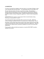
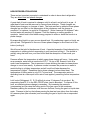
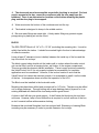
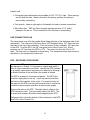
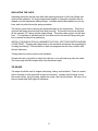
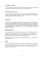
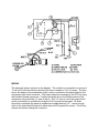
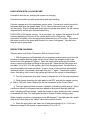
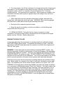
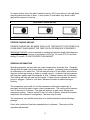
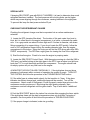
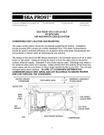
372 ROUTE 4 BARRINGTON, NH 03825 USA
TEL (603) 868-5720
FAX (603) 868-1040 1-800-435-6708
E-Mail:[email protected]
www.seafrost.com
ENGINE DRIVE R-12 SYSTEM
OPERATION & INSTALLATION
INSTRUCTIONS
NOTICE OF RESPONSIBILITY
It is the SEA FROST intent to provide the safest, most accurate and detailed instructions. SEA
FROST cannot be responsible for problems or damage caused by omissions, inaccuracy or
interpretation of these instructions.
SEA FROST is a registered trademark
Aspects of the SEA FROST design are covered by
US Patent #4,356,708
1
START UP PROCEDURE
for
RECENTLY COMMISSIONED
SEA FROST ENGINE DRIVE SYSTEMS
ATTENTION new SEA FROST owner or operator! PLEASE DO NOT
OPERATE THE REFRIGERATION SYSTEM UNTIL YOU READ THIS.
WARNING! Your SEA FROST System can be severely damaged and your warranty
will be invalid if these steps are not followed closely.
BREAK-IN PERIOD. DURING THE FIRST TWO HOURS OF OPERATION OF A NEW
COMPRESSOR, LIMIT RUNNING TIMES TO THIRTY MINUTES (FOUR SEPARATE
THIRTY MINUTE OPERATIONS WITH A REST PERIODS OF AN HOUR OR MORE)
AND ENGINE SPEEDS TO BELOW 1200 RPM.
1) Locate the SEA FROST Receiver/Filter/Drier (RFD). The location of this part varies
from boat to boat, but it is often found in the engine compartment, in a locker, or
beneath the cabin sole. It is a gray metal can about 8 inches high and 2.5 inches in
diameter, with brass fittings connecting it to copper tubing. (If you do not locate the
RFD quickly, follow the route of 3/8" refrigeration copper tubing, the smaller diameter
tube, from the engine compartment to the icebox. Along the route you will find the RFD,
along with other SEA FROST components). The RFD has a sight glass for viewing the
flow of refrigerant.
2) Start the boat's engine. Check to be sure the engine is pumping water.
3) Locate the SEA FROST Control Panel. With the engine running at a fast idle (900 to
1200 rpm), and while looking into the sight glass, have a helper turn the timer knob past
"10" to cock the switch and start the compressor. The engine should load, slowing
slightly.
4) MONITOR THE SIGHT GLASS CONTINUALLY. White foam should appear in the
sight glass indicating that the refrigerant is present. This foam may disappear quite
quickly, but IF NO FOAM IS EVIDENT, that is, if the sight glass does not show a
presence of refrigerant within a minute of operation the system is dead flat. DO NOT
CONTINUE TO OPERATE THE SYSTEM. OPERATION IN THIS MODE WILL RUIN
THE COMPRESSOR. Switch off the 12-volt panel breaker to prevent operation until the
problem is corrected. CALL US AT 603-868-5720.
2
5) If white foam is evident watch closely for a transition from foam to clear. A clear
sight glass indicates a sufficiently charged system. This point can be missed if proper
attention is not given. A FULL SIGHT GLASS AND AN EMPTY GLASS LOOK THE
SAME. It is possible for the sight glass to show large, almost stationary bubbles even
when the charge is sufficient, so it is important to differentiate between "foam" and
larger “bubbles”. The foam condition has velocity and direction, but the larger bubbles
are nearly stationary. If the foam does not clear the system is low on charge. CALL US
AT 603-868-5720 for trouble shooting and correction help.
There are three conditions of charge indicated by the sight glass:
1) A black or clear glass and no cooling indicates no charge. Turn off the
compressor at once.
2) A white foaming glass and some cooling indicates the system is undercharged or
has lost charge. Refer to the manual regarding leak checking and recharging.
3) A black glass and proper cooling indicates all is well.
RFD SIGHT GLASS DETAIL
EMPTY OR CLEAR
STATIONARY BUBBLES
FOAM/LOW
6) Feel the SEA FROST Block or Plate in the ice box five minutes after engaging the
timer switch. If the sight glass clears yet the Block temperature does not drop after 5
minutes of operation, CALL US AT 603-868-5720.
7) The compressor in a Sea Frost R-12 Engine Drive system is designed for R-12
only. Use of any refrigerant other than R-12 will damage the seals in your
compressor.
3
CONTENTS
OPERATION
GENERAL DESCRIPTION
ICE MAKING
MAINTENANCE
ZINC, CONDENSER: SKETCH
INSTALLATION
TUBE HANDLING, CUTTING, BENDING
COMPRESSOR, INSTALLATION
PULLEY MOUNTING
BELTS, COMPRESSOR
CONDENSER
BLOCK
VALVE CONTROL UNIT
SWAGELOK FITTINGS, MAKE-UP & RECONNECTING
RECONNECTING PRE-SWAGED FITTINGS
HOSE-TO-COMPRESSOR FITTINGS
RUNNING THE LINES; INSULATING LINES
RFD (RECEIVER FILTER DRIER
ELECTRICAL SYSTEM; WIRING; CONTROL PANEL; TIMER
WIRING DIAGRAM
ASSEMBLY INSPECTION CHECK LIST
REFRIGERANT HANDLING
ACCESS TO THE SYSTEM: SERVICE PORTS
TAPPING A CAN OF REFRIGERANT
CHARGE HOSE; VENTING THE CHARGE HOUR
CHANGING CANS; GAUGES
LEAK CHECKING
EVACUATION WITH VACUUM PUMP
NEW SYSTEM CHARGING
READING THE SIGHT GLASS
PROPER CHARGE AMOUNT: MAXIMUM CHARGE
CHECKING THE REFRIGERANT CHARGE
DISCHARGING THE SYSTEM
TROUBLE SHOOTING
RFD EXCHANGE
TROPICAL OPERATION MAINTENANCE
PRESSURE CHARTS
4
5
5
7
8
9
11
12
12-13
14
14
14
15
17
18-20
20
20
21
22
24
25
26
27
27
27
28
28
29
31
31
32
33
34
35
35
36
37
38-40
OPERATION ~ GENERAL DESCRIPTION
The SEA FROST Engine Drive is a cold storage refrigeration system powered by the
boat's engine. Cold storage is attained by rapidly freezing the solution contained in the
plate, creating a captive (replenishable) block of ice. The system uses a compressor
belt-driven by the boat's engine. The compressor has an electromagnetic clutch
controlled by the timer switch on the SEA FROST control panel. Refrigerant from the
compressor is piped to the SEA FROST Block or plate(s) in the icebox.
BREAK-IN PERIOD
REFER TO THE START UP PROCEDURE IN THE BEGINNING OF THIS MANUAL.
EVERY TIME THE SYSTEM IS RESTARTED FROM WARM, CHECK TO BE SURE IT
IS COOLING BEFORE OPERATING THE COMPRESSOR EXTENSIVELY.
OPERATION
STEP 1.
To operate the system, the engine must be running. This system is water-cooled and
depends on water being pumped by the engine. Water flow is most important, therefore
CHECK THE WATER FLOW FROM THE BOAT'S EXHAUST BEFORE OPERATION.
STEP 2. THE TIMER
The system may be operated at any engine speed and is not affected by heel angle.
When not under way, a fast idle will give good performance. Turn the timer switch
clockwise past "10" to cock the switch. From this "10" position, the switch may be
overridden to ""OFF" or advanced to the desired running time. The spring wound timer
will turn off by it’s self. When the timer is started, the red lamp will go on and the engine
should see a slight rpm drop (larger engines will be less affected).
Within 5 minutes you will notice the plate getting cold. After about a half hour, the plate
will become very cold and if the timer is on, the compressor may cycle on and off. The
maximum cold storage is generally attained within an hour. However you might
experiment with two shorter periods a day. There is no limit to "on" time.
WARNING: After 5 minutes of operation, check for a drop in the plate’s temperature by
feeling the plate with your hand. If no noticeable cooling has occurred, turn off the timer
switch. Check the charge level and check the water flow from the exhaust. TO
PROTECT THE COMPRESSOR, DO NOT OPERATE the system if this temperature
drop is not noted.
5
A SUGGESTION
As soon as the engine has stopped or the timer has run out, the plate will begin to warm
up as it absorbs heat (cools) the icebox. You might decide that it is a good idea to run
the unit in the last minutes of the day to provide ice for drinks. Short periods of
operation whenever the engine is on for other purposes will be beneficial. Maximum
storage will require that the plate be frozen. The plate may thaw (be above freezing)
and still not require running in refrigeration applications. Monitor the box temperature
itself.
DEFROSTING will be required. A heavy layer of frost or ice will reduce cooling.
Defrosting is very important in freezers.
Two shorter periods a day may be better than a long one once a day. When the
holdover freezing is complete the benefit of running is only to delay warming. There is
some help in that cooling of the contents of the box will increase holdover time but heat
("cold") moves slowly and it will be more efficient to wait and run again later. Using this
method the most rapid storage is developed, dissipated to the box and contents then
regenerated.
Experimentation will provide the best instruction on how the SEA FROST should be
operated on your boat.
6
ICE MAKING
WITH THE BLOCK SYSTEM
The best way to make Ice is by freezing the metal ice trays to the top of the block. Spill
some water on top of the block before an insulating layer of frost builds up, and then
place the trays on the block. This water under the trays provides the thermal contact
necessary and freezes within minutes, holding the trays securely.
If the block is well frosted, it may be necessary to allow the top surface of the Block to
defrost before operating the system to make ice. If the block is well frozen several
batches of ice can be made with out operating the compressor. By the same token ice
making does not require compressor operation for the whole period ice is forming.
MAKING ICE IN PLASTIC
Making ice in plastic self-closing bags will prevent spilling and make large amounts of
ice. A good method is to use a bag within a bag. Fill the inner bag with water, seal it,
and dry off the outside surface. The outer bag should be wetted to freeze it to the block.
Because the block freezes quickly, trays and bags hold fast. When the ice is ready, the
inner bag may be easily removed. Hit the frozen bag with a winch handle to break it up.
WITH VERTICAL TRAYS
Fill the vertical trays with water and hang them on the stainless steel rod on the face of
the plate. Try to get some water between the tray and the plate surface to increase the
thermal contact (to increase freezing ability).
The trays may take time to freeze after the plate is frozen and the engine compressor
has been switched off.
HARVESTING VERTICAL TRAYS
Plan to wait some time after the trays are frozen for them to thaw in a sink or away from
the plate in the refrigerator. When the outside surface is wet invert the tray and let the
ice slide out.
STORAGE OF ICE CUBES
After ice has been made and harvested, store it in sealable plastic bags in the
refrigerator or in the freezer. Leaving the ice in trays in contact with the block or plate
will allow the ice to melt if the plate goes above freezing.
7
MAINTENANCE
Like your engine, your SEA FROST needs periodic checking.
ROUTINELY CHECK:
1. Check the refrigerant charge, never operate the system without proper charge.
2. Check belt tension and condition.
3. Check compressor mounting and compressor bracket bolts.
4. Maintain the condenser zinc. Failure to maintain the zinc anode will cause
damage to the system.
5. Check all components and all bilge and engine room fittings for corrosion and wear.
BE SURE TO LOCATE AND INSPECT ALL FITTINGS AND COMPONENTS IN THE
SYSTEM. KNOW THE LOCATION OF ALL CONNECTION POINTS. Spray with a rust
inhibitor regularly. Corrosion unchecked in the marine environment will severely reduce
the life of your system.
6. Winter storage will require that the water-cooled condenser be flushed and filled with
an antifreeze solution to avoid damage from freezing. If the condenser is to be left dry
flushing with a good amount of fresh water to remove salt deposits is recommended.
CLEANING
The plate’s surface protects itself with layer of oxidation. You might find after a long
period of storage the plate will look chalky. This will not effect operation and is easily
cleaned up with a pot scrubber and soap.
TROPICAL OPERATION MAINTENANCE
A system that has operated for several years in the tropics or is in service in the tropics
may need condenser cleaning with muriatic acid. Refer to the data sheet on page 37.
8
DETAIL OF CONDENSER ZINC ASSEMBLY
To change the zinc, first close the engine seacock. Using two 7/16 open-end wrenches,
hold the brass plug and remove the outer nut. Carefully bend the ground strap away
form the plug. Remove the plug. Water will drain from the condenser. Using pliers hold
the zinc and unthread the plug. Should the zinc break in the holder, it may be cleaned
by heating the plug holder with a propane torch to melt the remaining zinc. Thread the
new zinc into the plug. Snug with pliers making sure that the zinc is not cracked or
stressed by over tightening. Use a pipe thread sealant on the plug thread. BE AWARE
THAT THIS IS A TAPERED PIPE THREAD. Thread the plug into the condenser
housing about 3/4 of the length of the plug. This should seal the connection.
EXCESSIVE TIGHTENING WILL STRESS THE CONDENSER HOUSING. Open the
seacock and check for leaks. Reassemble the ground strap and nut. NOTE that this is
an electrical connection. The brass plug and the ground strap should be free of
corrosion and oxidation. The final assembly should be sprayed with, or similar rust
inhibitor.
9
HOW REFRIGERATION WORKS
There are two important concepts to understand in order to learn about refrigeration.
They are latent heat and phase changes.
A great deal of heat is required to change a solid to a liquid, and a liquid to a gas. A
great deal of heat must be removed to reverse these changes. These changes are
called phase changes, or changes of state. The heat removed or added at these phase
changes has no effect on the temperature of the substances until the change is
complete. For instance, ice melts at 32 degrees F. Water freezes at 32 degrees F also.
Ice and water will remain at 32 degrees F until the freezing or melting process is
complete. Latent heat is this hidden energy required to make or break the bonds in a
phase change.
By evaporating liquid to a gas, we can absorb heat. By condensing a gas to a liquid, we
give up heat. Refrigeration is the use of these phase changes to move heat out of the
icebox (cooling it).
We all know that cold is the absence of heat. A practical example of heat absorption by
evaporation is rubbing alcohol evaporating in your hand and cooling it. The alcohol is
actually using the heat from your hand to boil and the absorption of heat cools your
hand.
Pressure affects the temperature at which a gas phase change will occur. Using water
as an example, water boils at sea level at 212.F. On top of Mt. Everest it boils at a
much lower temperature. The air pressure is lower allowing the water-to-steam phase
change to occur more easily. A pressure cooker increases the pressure on water to
restrict boiling to a higher temperature and will cook food faster because the
temperature is higher. Remember that a phase change involves latent heat. The
temperature of boiling water is only 212.F at sea level. The evaporation action is
absorbing heat at a rate equal to the rate of heat applied, preventing further temperature
rise.
Let's look at Refrigerant-12. R-12 will boil at minus 21 degrees F at sea level. By
evaporating liquid R-12 in the SEA FROST plate, heat is absorbed. To dispose of this
heat, a condensing phase change is necessary. By increasing the pressure
(compressing) we can raise the boiling point of the gas vapor at the condenser.
Seawater passing the condenser coils removes the heat, forcing the gas to a liquid state
again. Pressure is the key that allows passing the heat we have taken from the icebox
to a warmer place (the sea water) and converting the gas to liquid to be re-evaporated
again.
10
By causing R-12 to boil (evaporate) in the SEA FROST plate, we use the heat energy in
the plate. This activity cools the liquid solution in the plate, causing it to change phase
(freezing to a solid). By freezing this solution, we have increased its heat absorption
capacity more than 100 times. When the cycle is stopped (the compressor is turned off)
the plate will begin to absorb the heat that leaks through the insulation in the icebox.
The absorption will be at a constant temperature until the phase change to liquid
(melting) is complete. This is the principle of holdover refrigeration and the function of
your SEA FROST.
INSTALLATION
WORK HABITS
Installer's care should be stressed. No matter how good SEA FROST equipment is, its
performance and life are in the hands of the installer. To insure your work:
1. Read and understand this manual.
2. Follow Swagelok instructions carefully.
3. Install RFD last, the same day the system is charged.
4. Spend enough time leak-checking to be sure there are no leaks.
5. Thanks from all of us who have to guarantee your work.
There are two contaminants that will give you problems in a refrigeration system. They
are WATER and DIRT. Moisture is always present and cannot be eliminated; water in
this case refers to puddles and drops. Dirt is any solid. The installer's habits will be
most important in ensuring a trouble-free start-up. We have added a large receiver filter
drier (RFD) to take care of all dirt and moisture that might get into the system during a
careful installation. Moisture in the system is boiled off when the system is evacuated,
or it is captured in the desiccant. There is a screen in the expansion valve to prevent
dirt from plugging the valve.
Excess moisture that the RFD can't handle will plug the expansion valve with ice. This
ice stops the cycle. The only cure is to discharge the refrigerant, replace the RFD, reevacuate the system, and recharge it. This remedy takes time and is somewhat costly.
Keep the system clean and dry!
TUBE HANDLING
Installation is quite simple. All the copper tube comes to you with the ends capped.
Any routing of the tube must be done with the tube either taped or capped. Cap both
tube ends after each cut. Spare caps have been included.
Work with only one line at a time, and uncap only one end at a time.
11
TUBE CUTTING
Use only a tube cutter, hacksawing or any other method will introduce chips to the
system and distort the tube, making connections difficult and leak-prone. A small
miniature cutter is essential for this work. CUT SLOWLY to avoid a ridge on the inside
of the tube. We do not recommend reaming or dressing the cut, as it is very easy to get
chips of copper in the system that may cause trouble.
TUBE BENDING
Make all but the long sweep bends with a spring bender; one kink and the line must be
rerun. Don't add any more fittings than are absolutely necessary. Route all lines in
such a way that they are most direct but out of the way. Several inches of the end of
the tube going to a connector must be straight and round. Again, keep everything
sealed until you are ready to make that connection.
THE COMPRESSOR
The compressor is the first component to mount when installing the SEA FROST
system.
12
In mounting the compressor, consider the following:
When mounted, the compressor must not lay over on its axle axis more than 45
degrees from vertical. The port fittings, clutch coil wire, and the ground screw indicate
the top of the compressor.
The two service ports at the rear of the compressor must be accessible following
mounting of the compressor; servicing the system requires attaching charge hoses to
these ports. These ports are ¼” flare fittings with Schrader valves and sealed with
caps. The caps must be installed on the port to prevent it from leaking.
Allow clearance for compressor hose assemblies and belt adjustment if the
compressor is mounted under the engine. An optional low profile head is available that
requires no clearance and allows the hoses to exit straight back. Hoses with straight
compressor fittings are available as an option.
We recommend that the compressor be driven by its own belt. A single hi-power
"A" belt is all that is required to drive the compressor.
The compressor should be driven by a pulley five inches in diameter. The
compressor speed ratio should not exceed the crankshaft speed of the engine. This
ratio will give proper cooling at a fast idle and also allow operation at cruising RPM's.
The compressor will draw up to two horsepower, so it must be ruggedly bolted.
The extra pulley on the compressor may be used to drive a pump or alternator.
Engine motion is a torsional load concentric around the crankshaft. At the
crankshaft center, the engine is stationary which allows off-engine mounting of the
compressor. The compressor is not affected by side loads on the clutch pulley since
the construction of the free wheel pulley puts all load on the compressor case. This
protects the compressor bearing and shaft seal from failure and leaks from load. The
compressor is a very smooth device and may be hard mounted on the engine beds or
other structural members attached to the hull. It will not introduce any vibration or noise
by this mounting, and in many cases a much stronger mount is possible. The drive belt
will not transmit any engine vibration to the boat. The compressor pulley and the engine
drive pulley are large and will provide plenty of belt contact without excessive tightening,
so off-mounting will not "ground-out" a flex mounted engine.
The compressor may be mounted to a fabricated bracket that is bolted to the
engine.
A jackshaft may be used to drive the compressor.
The compressor may rotate in either direction.
13
PULLEY MOUNTING ON ENGINES
IT IS IMPERATIVE THAT THE EXTRA PULLEY BE MOUNTED TO THE ENGINE
CRANK PULLEY USING LOCK WASHERS OR THREAD LOCK ADHESIVE.
FAILURE TO LOCK ATTACHMENT BOLTS WILL ALLOW THE BOLTS TO LOOSEN,
CAUSING DAMAGE AND POSSIBLE DANGER FROM FLYING PARTS.
BOLTS SHOULD BE TIGHTENED TO A TORQUE SETTING RECOMMENDED FOR
THE DIAMETER AND GRADE OF BOLT BEING USED.
RECOMMENDED ADHESIVE/SEALANT: Loctite 271
COMPRESSOR BELTS
Various belts are available with an "A" section (1/2" 60 degree V). Specify a high power
belt. Fractional horsepower belts will stretch and wear rapidly. Cogged belts and kevlar
strand reinforced belts are available but not essential.
Belt length is measured on the back edge of a belt. An easy way to get a belt size is to
wrap masking tape around the pulleys with the compressor in the loose position. Break
the tape in one place and peel it off. Measure the tape to get the belt length. When the
belt size is determined record the brand and part number. Each belt manufacture has a
different sizing.
CONDENSER
The condenser should be connected into the raw
water line to the engine after the in-line strainer.
The SEA FROST condenser will not restrict water
flow to the engine, but be certain to avoid
restrictions in the water line by ensuring sufficient
hose diameter from the through hull to engine.
It may be connected on the discharge side of the
engine's raw water pump, but it must be connected
before any recirculating loops to the engine to be
certain it receives the full flow of the coldest water.
It MUST be mounted vertically: the zinc element is
at the bottom.
14
The zinc anode must be accessible as periodic checking is required. For best
service access to the zinc, mount the condenser with the zinc away from the
bulkhead. There is an alternate zinc location on the bottom allowing the plastic
plug and the zinc plug to be swapped.
Water must enter the bottom of the condenser and exit the top.
The bracket is designed to clamp to the middle section.
Be sure water fittings are made tight. A leaky water fitting may prevent engine
pump priming by leaking air into the circuit.
BLOCK
The SEA FROST Block is 6 1/4" x 9" x 13 3/4" (excluding the mounting tab). It must be
solidly fixed within the icebox. It should be mounted high in the box to take advantage
of natural convection.
Leave at least 2" clearance (more is better) between the inside top of the box and the
top of the block for ice trays.
The block copper tubing should exit the icebox wall to a place where the valve control
unit can be fitted, such as a hanging locker, sail locker, or the engine compartment.
This may provide the cleanest easiest installation. There is some moisture created by
the Valve/Control Unit if it is not properly insulated so accessibility for insulation
application must be considered. However, if the ice box location is such that the
Valve/Control Unit cannot be mounted outside, it is acceptable to install it on the inside
of the box. Its temperature does not effect the operation of the VCU.
The Block must be installed in the horizontal mode.
Mounting tabs have been drilled and countersunk for 1/4" bolts. The tabs may be drilled
out for larger fasteners. Through bolting with a large backing plate of plywood or to an
existing bulkhead will distribute the load and provide a good mount.
A cleat or shelf will also give good support. A shelf below the block may be used as a
cold zone. However, keep in mind that airflow is required to cool all sections of the box,
so don't constrict airflow with excessive shelving.
Be aware that a molded fiberglass liner has a sloped wall. Shimming or lowering Block
mounting may be necessary in order to provide clearance for ice trays.
15
A drilling template should be made. Drill 1 1/4" holes for the refrigerant tubes completely
through the icebox wall if the V/C/U is externally fitted. This allows recesses for the
white nylon bulkhead fittings on the block, and also facilitates removal of the block
without having to ruin the connection tubes by cutting off the Swagelok nuts and
ferrules. The larger holes also allow adding a moisture seal to any wooden bulkhead
that has been drilled by filling the holes with the spray foam provided.
Note that the fittings on the block are not connection points; there are no internal joints
in this system. Therefore field repairs cannot be made if the copper tubes are damaged
or cut too short.
809 PLATES
SEA FROST holdover plates mount with a
"Wellnut" expandable neoprene blind hole
fastener. A template or the part itself
should be used to locate the mounting
holes. Drill 1/4" pilot holes then increase
them to 1/2". Install the screw into the
mounting tab then screw the Wellnut onto
the screw. Install the plate pushing the
rubber mounts into the pre-drilled holes.
Tighten the screws.
PLATE LOCATION
The plate size, location, and plumbing are designed for each application.
16
VALVE CONTROL UNIT
For appearance and convenience of installation, the valve control unit mounts outside
the icebox. However, in certain applications it may be necessary to mount it inside.
Two Swagelok fittings fasten it to the block tubing protruding through the icebox wall.
Before cutting the tubing:
1. Leave a minimum of 1 ¼” of tube beyond the bulkhead.
2. Allow room for wrench access.
Ninety-degree elbows can be factory installed on the valve control unit to reduce the
space requirements if necessary.
The tubing will support the valve control unit.
The tubing must bottom in the fitting. A pencil mark 1" from the tube end should be
flush with the fitting nut face when the tube is seated in the fitting.
The VCU will attract moisture if not properly insulated. Be sure it is accessible for
proper insulating after the system has been leak checked and operationally tested.
For final installation of this unit see the Swagelok instructions.
17
NOTES ON SWAGELOK FITTINGS
Swagelok fittings come to you completely assembled, finger tight. (Pieces a, b, and c in
Drawing #1 are already together). They are ready for immediate use.
Disassembly before use can result in dirt and foreign material getting into the fitting and
causing leaks. If disassembly is necessary, reassemble per drawing.
This is double ferrule system. The most serious installation problem encountered with
SEA FROST is the improper assembly of these fittings. Be absolutely sure that you
assemble all fittings as in Drawing #1.
To ease assembly slacken the fitting nut slightly before pushing onto the tube, then
retighten with fingers before tightening with a wrench. This is to avoid cross threading.
Step 1. Always leave two inches of straight, undistorted tubing leading to all Swagelok
fittings to allow proper connection.
Step 2. Prior to inserting 1/2" tubing into Swagelok tube fitting, make a pencil mark one
inch from end of tube as a guide. Prior to inserting 3/8" tubing, make a pencil mark 5/8"
from the end of the tube as a guide.
Step 3. Insert clean, smooth tubing with the pencil mark into the Swagelok tube fitting.
You can be sure the tube is resting firmly on the shoulder of the fitting when the pencil
mark is flush with the nut.
Step 4. Tighten the Swagelok nut to a wrench snug* position. Scribe the nut with a
pencil at the 6:00 o'clock position (see drawing, step # 2).
* Wrench snug is the first point in the assembly tightening when the tube cannot be
pulled from the fitting, (when the ferrules tighten enough to contact the tubing).
Step 5. While holding the fitting body with a back-up wrench, tighten the nut one-andone-quarter turns (1+1/4). To do so, watch the scribe mark, make one complete
revolution, and continue to the 9:00 o'clock position. (See drawing, step #3).
18
DRAWING 1
STEP 1
Simply insert the tubing into the
SWAGELOK tube fitting. Make sure that
the tubing rest firmly on the shoulder of the
fitting and that the nut is wrench snug.
STEP 2
Before tightening the SWAGELOK
nut, scribe the nut at the six o'clock position
STEP 3
Now, while holding the fitting body steady
with a backup wrench, tighten the nut 1 1/4
turns. Watch the scribe mark, make one
complete revolution and continue to the
9 o'clock position. By scribing the nut at 6
o'clock position as it appears to you, there
There will be no doubt as to the starting
position. When tightened 1 1/4 turns to the
9 o'clock position you can easily see that
the fitting has been properly installed
19
SWAGELOK FITTINGS ARE TO BE TIGHTENED TO A TORQUE SPEC, NOT
INFINITE TIGHTNESS. BE SURE YOUR STARTING POINT IS WRENCH SNUG. A
DISTORTED TUBE MIGHT GIVE A FALSE STARTING POINT.
When making all connections, USE TWO WRENCHES. Don't allow the fittings to turn or
twist when tightening.
RECONNECTING PRE-SWAGED FITTINGS
Connections can be disconnected and retightened many times. When reconnecting,
insert the tubing with pre-swaged ferrules into the fitting until the front ferrule seats in
the fitting. Tighten the nut by hand. Rotate the nut about one-quarter turn with a
wrench (or to original one-and-one-quarter tight position). Then snug slightly with the
wrench.
SWAGELOK PERFORMANCE
Swagelok fittings have built-in spring interaction between the ferrules. This
compensates for temperature changes and allows the fittings to be reconnected many
times. As the fitting is tightened, a burnishing occurs between the body of the fitting and
the ferrules and between the ferrules and the tube. This action provides the tightest
connection available.
HOSE TO COMPRESSOR FITTINGS
Remove the plastic caps and rubber plugs
from compressor ports. Save these parts.
To install a tube "O" ring fitting on the
compressor, inspect the hose ends to be
sure they are clean and free from burrs.
Apply a drop of oil to the backside of the
nut. This will lubricate the nut to allow
proper tightening. Install the proper "O"
ring on the hose fitting. Uncap the
compressor port. Insert the correct fitting
in the compressor port. Tighten the nut
wrench snug. Using a back up wrench on
the compressor port, tighten one quarter of
a turn more. This fitting should feel tighter
than a SWAGELOK. The elbow should
not move when tightening is complete.
20
RUNNING THE LINES
PLANNING
The hose assemblies connecting the compressor to the copper tubing allow for
movement of the compressor after installation to enable work on and around the engine
with out having to disconnect the system. Leave some slack in the hoses and have
them directed the same way to allow compressor movement as necessary for access to
anticipated repair areas. Hose sets without adequate slack will stress the hose fittings
at the compressor causing failure of the fitting.
Keep tube runs as short as possible. The suction (return) line should be as direct as
possible with minimum bends.
The RFD is fitted with a sight glass. This glass must be visible for charging and
servicing the system. It can be viewed from up to a 45-degree angle but not from the
bottom or side. A mirror installed above the glass is one way of saving a poorly planned
installation. Avoid this if possible. Be sure the sight glass is visible!
Observe the inlet/outlet on RFD. It is labeled. The glass is offset toward the outlet.
The RFD should be installed only after all the lines are run and all other fittings are
made.
21
Helpful tools
• Coil spring-type tube benders are available for 3/8"-1/2" O.D. tube. These springs
are slid over the tube. Bend is formed in the spring, and then the spring is
removed by unscrewing.
• Ford wrench: Jaws at right angle to the handle for hard to access connections.
• Mini tube cutter: "IMP" by Gould Imperial requires less than 1 1/2" radius
clearance for the cut. This is essential to trim the block or plate tubing.
LINE CONNECTION PLAN
The compressor hose with the smaller elbow fitting attaches to the discharge side of the
compressor. The other end of the hose has a 3/8" Swagelok fitting. 3/8" tube runs from
the hose to the top of the condenser. From the bottom of the condenser, 3/8" tube runs
to the RFD. From the RFD, the 3/8" tube goes to the Valve Control Unit. Some
systems use 1/4" tube from the RFD to VCU. The return line from the VCU is 1/2"
tube. This line runs to a Swagelok-to-hose fitting. The compressor hose then returns to
the elbow on the compressor suction port.
RFD ~ RECEIVER FILTER DRYER
Because the RFD contains desiccant to absorb moisture and
the absorption is limited, it is important to unpack and install it
after all other connections are made. Leaving the RFD installed
on a partially open system may reduce its capacity by allowing it
to absorb moisture in free air before the system is sealed.
The RFD is a reservoir for excess refrigerant. The RFD also
contains a sight glass in the top. A pick-up tube extends from
the bottom of the canister to the outlet. For proper function of
the reservoir the RFD must be positioned as close to vertical as
possible to ensure proper operation at various heel angles.
Observe the inlet on the RFD. The sight glass is offset on the
RFD toward the outlet. The lines easily support the RFD. The
tie wraps with screws will hold the tubes supporting the RFD.
Refrigerant flow is from the bottom of the condenser to the RFD,
then to the Valve Control Unit.
22
INSULATING THE LINES
Insulating should be the last step after leak checking because it will cover fittings that
must be leak-checked. On long uninterrupted lengths of tubing the insulation can be
slipped over the tube before adding fittings. Insulation should be installed only on dry
lines, and only after the acrylic spray procedure.
The suction return line is carrying the expanded vapor to the compressor. This line is
cold and will attract moisture and frost when running. The suction return line includes
all the exposed 1/2" tubing and the larger fittings. The entire valve control unit will also
frost. It is important to insulate the line, the valve control unit and all fittings along the
line to prevent moisture from gathering.
INSTALL THE INSULATION IN A MANNER THAT WILL NOT TRAP WATER AROUND
A LOW POINT. Trapping salty bilge water in the insulation will reduce the operating life
of tubing and fittings. If the insulation is split and wrapped over the tube, install it with
the spit side down.
Tubing within the icebox need not be insulated.
Closed cell foam is provided to insert the tube into, or to split and wrap onto the tubes.
The foam wrap should be taped with vinyl electrician's tape.
TIE WRAPS
Tie wraps should be used to support the wiring, tubing, and insulation. There is a screw
hole in the end of each wrap that is used for mounting. Loosely loop the wrap, mount
the screw loosely, snug the wrap, tighten the screw, and trim the excess. Be sure not to
leave a sharp edge that might cut someone.
23
ELECTRICAL SYSTEM
The electrical system for the SEA FROST system includes a control panel comprised of
a timer switch, pilot light, circuit breaker, and the valve control unit.
CONTROL PANEL LOCATION
In choosing a location for the control panel, find the best location within the cabin
nearest the cockpit and engine controls. The panel is not waterproof. The system may
want to be activated whenever the engine is run.
OPERATION
With 12-volts (DC) available to the panel, turning the timer clockwise will engage the
compressor clutch, indicated by the pilot light. Turning the timer to “O” or shutting off
the 12v supply will shut off the unit. In the latter case, the timer will run down by itself.
If the system is turned on when the engine is off, the compressor clutch will engage, but
no cooling will take place. The light will come on, and normal operating current will be
drawn from the battery.
AMPERAGE DRAW
The compressor clutch will draw 3 to 3.5 amps per hour at 12 volts when the timer is
operated. A 24-volt system will draw 1.5 to 1.75 amps per hour. The timer panel
breaker is rated at 7-amps per hour and the wire is rated to about 20-amps per hour.
The supply to the timer should have at least a 10-amp breaker.
Because the compressor is switched on only when the engine is on, no power is taken
from the batteries.
TIMER
The timer is a spring wound device that must be "cocked" in order for it to disconnect
when it returns to the "off" position. For this reason, it is necessary to turn it clockwise
past "10". After the timer is cocked, it may be set to any time reading and may be
manually overridden to "off".
24
WIRING
The electrical system is shown in the diagram. The red wire is connected to a source of
12 volts (DC) and should be protected by a fuse or breaker of 10 to 15 amps. The blue
wire is the power to the compressor clutch, and is connected to the black pigtail on the
compressor with a butt connector. The brown wires are connected to the VCU by using
the insulated female connectors. Connect the white wire to the Phillips screw on the
compressor along with the 3 ft. wire in the kit. This 3 ft. wire is run to the engine block
and is connected to a suitable bolt using the 3/8" ring terminal provided. All wires
should be routed after the panel is installed and supported every 18". Leave enough
slack in the wire behind the panel to allow removal of the panel for service. Cut off any
excess wire before making the connector.
25
DISPLACING OIL IN NEWLY INSTALLED COMPRESSOR
The compressor is shipped with the proper amount of oil for the system. The oil must
be displaced from the cylinders before the compressor may be turned by the boat's
engine. After completing all the connections, turn the outer face of the compressor
drive disk for at least five turns by hand.
ASSEMBLY INSPECTION CHECK LIST
1. Check the lines to be sure they are properly routed. Check to see that the
compressor discharge connects to the top of the condenser and the water line enters
the bottom of the condenser.
2. Check to see that the RFD is installed observing the inlet-outlet.
3. Check that the RFD sight glass can be seen.
4. Check all the connections with wrenches to be sure they have been made up.
5. Check the belt and compressor bolts for tightness.
6. Check to make sure the compressor is mounted in an upright position.
7. Check the panel wiring by starting the timer switch. The pilot lamp should come on,
and compressor clutch should click.
8. Check the neatness of the installation: sufficient service accesses, secure wiring,
and make sure tubing is supported to prevent damage and chafing.
9. Check the condenser zinc access to see that it is serviceable.
26
REFRIGERANT HANDLING
SEA FROST is charged with REFRIGERANT-12. R-12 is the common name and
number given to the chemical composition DICHLORODIFLUOROMETHANE
(CC12F2). It is almost odorless, nontoxic, non-corrosive, non-irritating, and nonflammable. Its boiling point is -21.F at sea level. It was used in most household
refrigerators and in auto air conditioning systems. R-12 is now available in 30 lb
cylinders.
Refrigerant is either a vapor or liquid. To supply vapor to a system, keep the refrigerant
can in the upright position. To supply liquid to the system, invert the can, valve top
down. Be sure the can is handled carefully to ensure the correct refrigerant condition is
supplied.
SAFETY
R-12 is non-toxic, however, liquid R-12 will freeze skin. It's especially dangerous to the
irreparable tissues of the eyes. --WEAR EYE PROTECTION-WARNING. When charging or working on the system with the engine running, watch
out for MOVING BELTS AND PULLEYS. Loose clothes and long hair can pull you into
a belt. PLEASE BE CAREFUL.
WARNING. NEVER OPERATE A SYSTEM WITH THE HIGH SIDE (DISCHARGE)
OPEN TO THE REFRIGERANT SUPPLY. Pressurization of the supply can beyond its
normal pressure could cause it to burst.
ACCESS TO THE SYSTEM ~ SERVICE PORTS
The service ports are two small, capped Schrader valves on the compressor. The ports
are labeled "D" and "S", or "Discharge" and "Suction". The valves are the access to the
system and the caps are to seal the system. Without the caps the valves may leak. Be
sure the caps are installed tightly after charging or service.
TAPPING A CAN OF REFRIGERANT
Be sure the can of R-12 is clean and dry. Any contaminants on the top of the can or in
the hose will enter the system. First, install the clamp assembly on the top of the can.
Next, screw the valve wheel into the valve body, closing the valve. The metal point will
protrude from the gasket, but it will make its own seal while piercing the can. Be certain
that the gasket is present and is smooth and elastic. Now, with the can upright, screw
the valve body assembly into the clamp on the can, turning until the point pierces the
can and the rubber gasket has sealed. The can is now tapped.
27
VENTING THE CHARGE HOSE
To avoid pulling air or other contaminants into the system, it is necessary to vent the air
out of the hoses that are used to carry R-12 into the system. To vent the hose, open
the can tap valve with the can upright (vapor) to allow pressure to escape and then
make the connection as this vapor is escaping. Follow this procedure when adding
refrigerant to an evacuated system or to a system low on charge.
CHANGING CANS
Close the valve on the empty can. Unscrew the can from the valve body. Some
pressure may be present. Let this drop before completely removing the can tap. Switch
the clamp to the other can, and rethread onto the valve body.
GAUGES
Gauges must be used in the evacuation and charging. They will provide information on
system performance.
Gauge sets consist of two gauges installed in a manifold with two valves. The left
gauge (blue) is a compound device, it indicates pressure and also vacuum. The right
gauge (red) indicates pressure only. The valves open a center port (yellow) to the left
or right side respectively. Operation of the valve is only necessary when moving
refrigerant or evacuating. With the valves closed, the gauges read the pressures of the
connection points. The red hose is connected to the discharge side of the compressor;
the blue hose is connected to the suction side.
28
Charging with the gauges should be done through the blue side. The center hose is
connected to the can tap. Be sure to vent the hoses to displace any air that might be in
them.
TO INSTALL GAUGES ON A CHARGED SYSTEM, with the system off, attach the
hoses to the compressor. Vent the hoses at the manifold body by loosening the fittings
for a few seconds.
TO REMOVE THE GAUGES, turn off the compressor, wait for the pressure readings to
equalize, and then rapidly unscrew the hoses at the compressor. Re-cap the service
ports.
Keep your gauges clean. Inspect the rubber gaskets on hoses, leak-check gauge valve
packing and all hose connections. Prior to use, any oil should be blown out of the
hoses. The end of the hose that contains the depressor core is the end, which attaches
to the compressor service port. Check and reset the "O" on the low side gauge, if
necessary.
LEAK CHECKING
After all the equipment is mounted and connected, leak testing should be performed.
This is a very important step, which should be done with diligence. A leak will cripple
this system. Please take the time needed to be sure all connections are tight.
ABOUT PRESSURES
Refrigerant in a saturated condition, part liquid and part vapor will exert a pressure that
is a function of its temperature. The higher the temperature the higher the pressure.
Avoid leak checking in cold weather.
A refrigerant leak will show up under moderate pressure. A leak is not a function of
pressure once the pressure is high enough to show up on leak-checking equipment.
To leak check a new system, install the gauges and a can of refrigerant on the suction
port of the compressor. With the can in the inverted (liquid) position, open the valve and
feed in about 1/2 of a can of refrigerant, shaking the can, adding more if needed. Close
the valve and begin an inspection of all connections you have made.
In cold weather, it is possible to raise the pressure in the system by warming the plate
with a light bulb.
29
There are two ways to leak-check a pressurized system:
1. Soap bubbles (a solution of dish soap and water works well).
2. Electronic leak detector (probe senses presence of halide refrigerant molecules).
TO CHECK WITH BUBBLES
Soap each connection and observe all sides of the connection with a bright light and a
mirror. A leak will blow bubbles. Without careful examination and plenty of pressure
this test is not reliable.
TO CHECK WITH AN ELECTRONIC DETECTOR
Slowly trace the area with the probe. Refrigerant is heavier than air; trace below the
fitting. Most units can be calibrated to home in on a leak. We use and recommend
electronic detection. TIF brand detectors can accurately detect leaks as low as 1/2 oz
loss per year. This sensitivity exceeds SEA leak specifications. Be sure to test the
operation of the detector.
IF A LEAK IS DETECTED
Try tightening the fitting nut slightly more. If the leak is not stopped, it is possible that
the fitting was assembled incorrectly. Discharge the refrigerant, and then disconnect
the fitting for inspection.
SPECIAL NOTES
• Be aware that propellants and solvents in sprays and foams may upset electronic
detectors.
• To confirm a leak detected with a detector use bubbles and be sure it is a leak and
not some erroneous vapor that is upsetting the machine.
• Electronic detectors do not function below 40.F.
• A good leak detector is able to pick up leaks as low as 1/2 oz per year.
After satisfactory leak testing, evacuate the system.
30
EVACUATION WITH A VACUUM PUMP
Evacuation removes air, readying the system for charging.
Evacuate the system only after pressurizing and leak checking.
Connect a gauge set to the compressor service ports. If pressure is noted recover the
refrigerant and when the gauge reads "O" psi, connect the center hose to a high
vacuum pump. Start the pump and slowly open the gauge hand wheel. As the vacuum
drops below 20 inches open the hand wheel fully.
EVACUATE to the highest vacuum. On a new clean, dry, system, this requires 30 to 45
minutes depending on the size of the system and the size of the pump. When
evacuation is finished, close the gauge hand wheel and turn off the pump. Disconnect
the center hose from the pump and connect it to a can of refrigerant. Vent the hose
from can tap to gauge body.
NEW SYSTEM CHARGING
This procedure must follow "Evacuation With A Vacuum Pump".
1. With the gauge set still attached to the compressor suction service port from the
previous procedure and the gauge valves closed, attach the refrigerant can to the
center hose of the gauge set (yellow). Open the supply valve and purge the yellow
hose by cracking the hose end fitting at the gauge set. Open the low side gauge and
add about 10 oz of R-12 to the system, then close the gauge wheel. Now perform a
second complete leak check as before. If leak is found, correct the leak immediately,
discharge system, re-evacuate, then begin this step "1" again. Pumping the system
down, evacuating, with a leak in the system pulls air into the system, contaminating it.
2. Turn the compressor drive disk 5 times to displace the oil in the new compressor.
3. While closely observing the sight glass in the RFD, and with the engine running
at 1000 to 1200 rpm, have a helper turn on the compressor at the Control Panel.
4. The sight glass will show a stream of bubbles, indicating a partial charge. When
a sufficient amount of refrigerant has been added to the system the sight glass will
clear, indicating sufficient charge. Install the charge as vapor shaking the can if needed
to accelerate the flow. The timer panel should be turned off while changing cans.
When charging a system in temperatures over 80 degrees F. the sight glass will usually
clear as the return line as the Valve Control Unit becomes frosted.
5. When the sight glass runs clear, top off with approximately 4 oz. (1/4 of can).
Maximum charge for the system is approximately 18 oz of R-12.
31
6. On a new system, turn off the compressor for several minutes after charging, and
then restart it. Run the engine at slow speed, less than 1200 rpm, with several on/off
compressor cycles. Allow 1 to 2 minutes "off" periods between 2 to 15 minutes
operating periods. This equalizes the oil distribution. When charging is complete, stop
compressor and allow entire system to equalize and for the fittings to dry: an hour in
most conditions.
7. When observation and test operations have been complete, disconnect the
charge hose, and replace the service port caps. WARNING: When removing gauges,
allow pressures to settle before removing the discharge side hose.
8. Re-check all the connection points for leaks.
9. Spray the acrylic rust coating, or similar rust inhibitor, on all the fittings and
components when they are dry.
10. BREAK-IN PERIOD. During the first four hours of operation of a new
compressor, limit running times to thirty minutes with an hour rest period and engine
speeds to below 1200 rpm. Monitor charge level.
READING THE SIGHT GLASS
A clear sight glass when the compressor is operating signifies a sufficiently charged
SEA FROST Engine Drive System. To determine the meaning of "clear", notice the
appearance of the RFD sight glass when the system is at rest with the compressor off.
This is a "clear" glass.
WARNING: A clear sight glass can also indicate a completely EMPTY system. Any
time the compressor is started, a white stream of foam should appear in the sight glass
indicating that refrigerant is present. This foam may disappear quite quickly, but IF NO
FOAM IS EVIDENT, the system is empty. DO NOT OPERATE THE SYSTEM if empty.
Operation in this mode will ruin the compressor. Turn off the main breaker to the control
panel to prevent operation until system can be properly leak tested and recharged.
White fast moving foam with the compressor operating indicates an insufficient charge
level. Watch closely for a transition from foam to total liquid, indicated by a clear sight
glass. This transition point can be missed if proper attention is not given. Also, IT IS
POSSIBLE for the sight glass to show large bubbles even when the charge is sufficient,
so it is important to differentiate between "foam" and "bubbles". The foam condition has
velocity and direction; the bubbles are large, temporary, and nearly stationary. Do not
try to chase away these larger bubbles with more refrigerant. Overcharging must be
avoided. Air in the system may give a false sight glass reading, which could lead to
overcharging. If in doubt, discharge a suspected overcharged system and charge.
MONITOR THE SIGHT GLASS CONTINUALLY since the glass will not indicate when
the system is overcharged.
32
In a warm system, when the plate is above freezing (32.F) upon start-up, the sight glass
may take several minutes to clear. A cold system, in cold water, may show a clear
glass within seconds of start-up.
RFD SIGHT GLASS DETAIL
EMPTY OR CLEAR
STATIONARY BUBBLES
FOAM / LOW
PROPER CHARGE AMOUNT
PROPER CHARGE WILL BE MORE THAN 14 OZ, TOPPING OFF THE SYSTEM TO A
CLEAR SIGHT GLASS ABOUT THE TIME THE PLATE REACHES 32 DEGREES F.
MAXIMUM CHARGE can be computed by multiplying liquid line length (the distance in
feet of 3/8" tubing from bottom of condenser to VCU) by 1/3 ounce of R-12, and then
adding 12 ounces. DO NOT EXCEED THIS AMOUNT.
GENERAL INFORMATION
Operating pressures will vary with rpm, water temperature, and water flow. Generally,
the high side will peak with a warm plate in two minutes. Increasing pressure indicates
an overcharge or no water flow. The low side will drop to 25 psi rapidly, and will then
drop two pounds per minute or faster to a slight vacuum. However, low side pressure
will drop more rapidly when the seawater is cold. A deeper vacuum will be indicated.
This reading will vary with rpm and line length. A deep vacuum indicates the valve is
frozen or plugged. Failure to "pull down" indicates the valve is malfunctioning or
flooding.
The temperature control will cut out the compressor clutch when evaporator is
saturated, and will cut back in upon a rise in temperature. This cycling will be random
from 30 seconds to 3 minutes. The plate will continue to gain some storage with
compressor cycling. There is no limit to the "on" time of system, however the system
may freeze the contents of a refrigerator. The timer may be reset.
The compressor case will feel warm due to its double head and internal discharge
passage.
Every valve control unit has been operated prior to shipment. There are no field
superheat adjustments.
33
SPECIAL NOTE
If charging SEA FROST gear with BULK CYLINDERS, it is hard to determine how much
refrigerant has been installed. The feed pressure with a bulk cylinder can be higher
which may cause skipping through the condenser, causing bubbles in the sight glass.
To prevent this keep the feed pressure below 20 psi.
CHECKING THE REFRIGERANT CHARGE
Checking the refrigerant charge must be incorporated into a routine maintenance
schedule.
1) Locate the RFD (receiver filter drier). The location of this part varies from boat to
boat, but it is often found in the engine compartment, in a locker, or beneath the cabin
sole. It is a gray metal can about 8 inches high and 2.5 inches in diameter, with brass
fittings connecting it to copper tubing. If you do not locate the RFD quickly, follow the
route of 3/8" refrigeration copper tubing, the smaller diameter tube, from the engine
compartment to the icebox. Along the route you will find the RFD along with other SEA
FROST components). The RFD has a sight glass for viewing the flow of the refrigerant.
2) Start the boat's engine. Check to be sure the engine is pumping water.
3) Locate the SEA FROST Control Panel. With the engine running at a fast idle (900 to
1200 rpm), and while looking at the sight glass in the RFD, have a helper turn the timer
knob past "10" to cock the switch and start the compressor. The engine should load.
An empty system will put very little load on the engine.
4) MONITOR THE SIGHT GLASS CONTINUALLY. If the sight glass does not show
presence of refrigerant within a minute of operation the system is empty. TURN OFF
THE SYSTEM, and follow the procedure in the TROUBLESHOOTING section.
5) If the white foam is evident watch closely for the transition to "clear. If the glass
indicates insufficient charge level, additional charge will be needed. Turn off the
compressor. Attach a can of Refrigerant-12 with a properly vented charge hose to the
compressor suction service port. Monitoring the sight glass continually, start
compressor and add refrigerant until the glass clears. Top off with about 4 additional
ounces.
6) Feel the SEA FROST plate in the icebox five minutes after engaging the timer switch.
If the sight glass clears yet the plate’s temperature does not drop after 5 minutes of
operation, turn the system off and follow the procedure in TROUBLE SHOOTING.
7) If the proper charge is indicated, make ice go sailing.
34
DISCHARGING THE SYSTEM
Before the connections can be disconnected, the refrigerant charge must be
discharged. Connect a gauge set to the suction service port and slowly vent the
refrigerant through the open hose regulating the gauge valve prevent oil or liquid from
being discharged into the recovery machine. Recover all refrigerant until the system
reads 10” of vacuum for 10 minutes.
TROUBLESHOOTING
The most common problems that can occur in a SEA FROST Engine Drive System are:
1. Loss of refrigerant charge resulting from leaks.
2. Moisture or dirt plugging the valve.
3. Compressor malfunction due to loss of refrigerant charge.
4. High-pressure cutout switch cycling due to overcharging.
STEP 1. Gather information as to the nature of the problem before continuing operation
of the system. A leak often leaves a trace of oil. Inspect fittings, hoses, and tubing for
wear, corrosion, and chafe. Operate the compressor as little as possible until the
trouble is corrected.
High pressure switch cycling is indicated by the compressor and indicator lamp turning
off when starting a warm system, or if the cooling water is not flowing. Determine the
condition by checking water flow from the engine exhaust. If the water flow is not at
fault recover some refrigerant. At one-minute discharge intervals, try to operate the
compressor. Shut off the hand wheel valve on manifold gauge set before operating.
Proceed until the compressor stays on without cycling during initial pull down. Check
the sight glass for proper charge. Be sure sight glass still clears.
If icebox and SEA FROST plate is warm and pressure readings are below 50 psi with
compressor off (in 50 degree F or higher ambient conditions), pressurize system with R12 and leak-check. After leaks have been located, repaired, and tested, install new
RFD (Receiver/filter/drier) - see instructions below in Step 3.
If pressure reading is over 50 psi with compressor off, proceed to check charge level via
sight glass and charge if needed. Charge loss indicates a leak that MUST be
corrected.
STEP 2. If a system continues to operate inefficiently after Step 1, check for moisture
or dirt plugging the valve. Run the system, observing closely the gauge readings and
plate temperature, noting the following.
35
If system is warm upon start-up, a DIRT-PLUGGED Valve will show an immediate deep
vacuum reading on low side. Contact Sea Frost for cleaning techniques.
Moisture plugged valves are indicated by deep vacuum readings on low side after 1 to 5
minutes operation from warm, followed by any combination of these symptoms:
• High side compressor discharge fitting temperature drops from hot to warm
• Suction line from Valve Control Unit remains warm.
• Compressor load on engine drops.
Moisture enters either through a low side leak or during initial installation and will freeze
at Valve Control Unit, reducing or eliminating refrigeration. Turning off system and
allowing valve to warm above freezing, and then restarting may temporarily solve the
problem. If not, change RFD.
STEP 3. To change a saturated RFD, allow system to warm to ambient temperature,
preventing moisture from condensing in circuit upon opening. A light bulb in icebox will
speed the warming of plate. Recover the refrigerant from the system through the
suction service port SLOWLY to prevent liquid and oil from escaping. WARNING:
BEFORE DISASSEMBLY OF ANY PART MAKE SURE CHARGE IS COMPLETELY
RECOVERED. With a backup wrench holding the brass body of the Swagelok fittings,
loosen and back off the nuts. The tubing may be pulled out of the fittings. Remove the
RFD. Replace only with an identical unit.
Install a new RFD, observing proper inlet ("IN") position. Refrigerant flow is from the
condenser to the "IN" side. The sight glass is offset toward the "out" side. Remake the
Swagelok fittings (1 ¼ turn from wrench snug. Leak check, evacuate and charge.
NOTE: To ensure removal of system moisture use a high vacuum pump, and evacuate
the system with the highest possible ambient and plate temperatures. A light bulb or
heat lamp in contact with plate is a good technique.
MOISTURE IS A SYMPTOM. Carefully leak check the low side of the system if
moisture becomes a problem. Moisture leaks in!
36
MAINTENANCE FOR UNITS IN TROPICAL WATERS
ZINCS
This is the most important procedure. A full flow sea frost condenser without a zinc or
without the bonding strap connected will last a very short time. Be sure to check the
wear by inspection. Replace every six months or sooner if inspection reveals excessive
wear.
If the zinc breaks in the brass plug, remove the remaining zinc by melting it with a
propane torch.
ALKALI SCALE
Condensers will scale after several years in warm water causing higher head pressures
due to the scale interfering with the heat exchange. Remove the zinc and plug the hole
in the condenser with a 3/8” npt pipe plug. Warning: leaving the zinc in place makes a
big battery upon adding acid. This will produce heat and smoke. Don't forget to remove
the zinc. Remove the top hose on the condenser and pour muriatic acid into the
condenser until it boils out the top.
WARNING: Be sure to follow safety precautions on the muriatic acid container.
Most muriatic acid is bottled at 5%-7%. This concentration is what we recommend.
Boiling (foaming) will stop in (4 or 5 minutes. There is no danger of damage to the
condenser. Reconnect hose to the engine and start the engine with the through hull
open. After a minute or two of operation to flush out the acid, shut off the engine and
through hull and replace the zinc.
CLUTCH COILS
These fail from heat breaking down the wire insulation in the winding. Damaging heat
can be caused by operation with too much charge and by scaling. Clean the
condenser. Be sure the charge is minimum for a clear glass. No more than 24 ozs is
needed for most systems. A single plate or block system will need less than 24 ozs of
refrigerant.
37
38
39
40