1
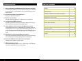
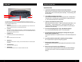
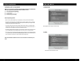
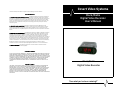
Covert Video Systems The limited warranty stated herein is subject to all of the following terms and conditions. TERMS AND CONDITIONS 1. NOTIFICATION OF CLAIMS: WARRANTY SERVICE: If Purchaser believes that the product is defective in material or workmanship, then written notice with an explanation of the claim shall be given promptly by Purchaser to the Manufacturer but all claims for warranty service must be made within the warranty period. No repair or replacement of any product or part thereof shall extend the warranty period as to the entire product. The specific warranty on the repaired part only shall be in effect for a period of ninety (90) days following the repair or replacement of that part or the remaining period of the product parts warranty, whichever is greater. Clock/Radio Digital Video Recorder User’s Manual 2. EXCLUSIVE REMEDY: ACCEPTANCE: Purchaser’s exclusive remedy and the Manufacture’s sole obligation is to supply all labor necessary to repair any product found to be defective within the warranty period. Purchaser’s failure to make a claim as provided in paragraph 1 above or continued use of the product shall constitute an unqualified acceptance of such product and a waiver by Purchaser of all claims thereto. 3. EXCEPTIONS TO LIMITED WARRANTY: The Manufacturer shall have no liability or obligation to Purchaser with respect to any product requiring service during the warranty period which is subjected to any of the following: abuse, improper use, negligence, accident, modification, failure of the end-user to follow the operating procedures outlined in the user’s manual, failure of the end-user to follow the maintenance procedures in the service manual for the product, attempted repair by non-qualified personnel, operation of the product outside of the published environmental and electrical parameters, or if security seal has been defaced, altered, or removed. The Manufacturer also excludes from warranty coverage products located outside the United States, and consumable items such as fuses and batteries. Items not manufactured by Backgrounds Unlimited, Inc but included in system bought by Purchaser are limited to original manufacturer’s warranty and will be repaired by Backgrounds Unlimited, Inc. on cost of material basis. 4. PROOF OF PURCHASE: The purchaser’s dated invoice must be retained as evidence of the date of purchase and to establish warranty eligibility. DISCLAIMER OF WARRANTY EXCEPT FOR THE FOREGOING WARRANTIES, THE MANUFACTURER HEREBY DISCLAIMS AND EXCLUDES ALL OTHER WARRANTIES, EXPRESS OR IMPLIED, INCLUDING, BUT NOT LIMITED TO ANY AND/OR ALL IMPLIED WARRANTIES OF MERCHANTABILITY, FITNESS FOR A PARTICULAR PURPOSE AND/OR ANY WARRANTY WITH REGARD TO ANY CLAIM OF INFRINGEMENT THAT MAY BE PROVIDED IN SECTION 2-312(3) OF THE UNIFORM COMMERCIAL CODE AND/OR ANY OTHER COMPARABLE STATE STATUE. THE MANUFACTURER HEREBY DISCLAIMS ANY REPRESENTATIONS OR WARRANTY THAT THE PRODUCT IS COMPATIBLE WITH ANY COMBINATION OF NON-MANUFACTURER’S PRODUCTS PURCHASER MAY CHOOSE TO CONNECT TO THE PRODUCT. LIMITATION OF LIABILITY THE LIABILITY OF THE MANUFACTURER, IF ANY, AND PURCHASER’S SOLE AND EXCLUSIVE REMEDY FOR DAMAGES FOR ANY CLAIM OF ANY KIND WHATSOEVER, REGARDLESS OF THE LEGAL THEORY AND WHETHER ARISING IN TORT OR CONTRACT, SHALL NOT BE GREATER THAN THE ACTUAL PURCHASE PRICE OF THE PRODUCT WITH RESPECT TO WHICH SUCH CLAIM IS MADE. IN NO EVENT SHALL THE MANUFACTURER BE LIABLE TO PURCHASER FOR ANY SPECIAL, INDIRECT, INCIDENTAL, OR CONSEQUENTIAL DAMAGES OF ANY KIND INCLUDING, BUT NOT LIMITED TO, COMPENSATION, REIMBURSEMENT OR DAMAGES ON ACCOUNT OF THE LOSS OF PRESENT OR PROSPECTIVE PROFITS OR FOR ANY OTHER REASON WHATSOEVER. Clock/Radio Digital Video Recorder “See what you’ve been missing!!” INTRODUCTION APPENDIX The Clock/Radio DVR is a Digital Security System designed to record/retrieve up to 1 channel of video at the same time. It adopts a digital image compression technology to compress the input channel video streams, and uses a SD Memory to record the compressed video stream. The Clock/Radio DVR is manufactured to satisfy international safety standards. Review the following safety precautions to avoid injury and prevent damage to the system or any products connected to it. Some things to remember before use: 2 • Use a proper power source. Do not operate this product from a power source that applies more than the specified voltage (AC120V). • Do not operate in wet and dusty conditions. Keep product surfaces clean and dry. Avoid placing the Clock/Radio DVR in areas like a damp basement or a dusty hallway. • Do not expose this product to rain or use near water. If the product gets wet, unplug it and contact an authorized dealer immediately. • Do not operate with suspected failures. If there are any unusual sounds or smells are coming from the Clock/Radio DVR, unplug it immediately and contact an authorized dealer or service center. • Handle the Clock/Radio DVR carefully to avoid damaging the product. If you accidentally drop the system on any surface, it may cause a malfunction. If the Clock/Radio DVR doesn’t work properly due to physical damage, contact an authorized dealer for repair. 19 23 TROUBLESHOOTING 9. What is the limitation of the SD Memory size that I can install in the system? A standard capacity SD Memory not a high capacity is required. Most 1-2GB cards are standard capacity. Some 4GB Memory cards are standard capacity but most are high capacity. 10. How can I erase all data on the hard disk drive? Refer to your computer documentation. 11. Why do I need a password? You need a password to SD Memory. The password is for your protection. 12. I forgot my password. What should I do? Press the "Pause" button five times and it will reset the settings to the factory default. The password will reset to the factory default of (0000). 13. Can my desktop PC read the video data on SD Memory in the system? The file format used in the unit is not supported by any PC operating systems, including Windows or Linux, so you can’t access the SD Memory using your PC. But if you use the exclusive viewer, you can access the system’s SD Memory using your PC. The software for the SD Memory PC viewer is on the CD provided with the system. 14. What happens if I install my PC SD Memory into the device? You can use a PC SD Memory in the Micro DVR. However, once it runs in the system, it will delete any PC operating system and files on the SD Memory. 15. What kind of SD Memory should I purchase to run the system? Standard capacity SD Memory, not high capacity. 16. What is the capacity to record? Most standard capacity SD memory is from 1—2GB of storage. Some 4GB Memory cards are also standard but most are high capacity. 18 TABLE OF CONTENTS Overview 4 Remote Controller Panel 5 Setup Procedures 6 SD Memory Installation and Connection to a Monitor 7 OSD Menu and Main Menu 8 Record Mode and Video Quality 9 Event Mode 10 Alarm Setup and Motion Setup 11 Schedule Setup and Search 12 Sub Menu 13 Password Change and Time Set 14 Brightness and Video 15 Memory Sync and Reset Default Settings 16 Troubleshooting 17 Appendix 19 Warranty information 20 OVERVIEW TROUBLESHOOTING Rear View of Clock/Radio TROUBLESHOOTING 1 3 2 4 6 1. I pushed the menu button but it doesn’t show the menu directory. When the unit is in record mode no button on the front panel will work. The red light below the REC button is on when the system is recording. To end recording, press the STOP button. 2. I see an SD error message on the screen. If you see the error messages such as “SD Memory Check Fail”, “SD BUSY Error”, “SD initial is Error”, pull out and put in the hard disk drive or replace the SD memory. Also make sure that SD rack is firmly locked. 3. I push the record button but nothing records. Make sure that there are no slash ( -- ) signs on the Record Schedule Menu. If you see any slash ( -- ) signs, change it to the “T” sign using the select button. Or change it to the “S” sign if there are any sensors installed on the system and you prefer motion sensor recording. 4. Can I record everything 24 hours 7 days a week without stopping? Yes. In the Record Schedule Menu, select “T” for all time periods. 5. Can I prevent other people from stopping the recording while I am gone? Would creating a password do it? The only way to prevent this is to place the device in a room where nobody else can enter. 6. Can I still record all the events while I review the previous recording? No. The system doesn’t support recording during playback. 7. How long is the warranty period? One year after the date of purchase. We will gladly offer replacement for all defective units. 8. What is the correct format for using a SD Memory? You may not need to change the format / FAT32 after you purchase SD Memory and install it into the device. Check the documentation that came with your SD Memory. 5 This chapter briefly describes the functions of the Clock/Radio DVR. These features can also be activated by using the remote control. For more details on the set-up and operation of the system, refer to the Clock/Radio DVR MENU section. 1. VIDEO OUT Connect the Clock/Radio DVR to a TV or monitor using a BNC cable. If you connect one of the VIDEO OUT ports to the VCR, you can backup data with the VCR. 2. AC 120 Volt This is used to connect AC adapter jack for DC power. Connect the power adapter to the Clock/ Radio DVR. Use only the AC adapter that comes with the unit. The Clock/Radio DVR contains a power supply that is enclosed in the unit. 3. SD MEMORY SLOT The SD Memory slot holds the standard SD Memory card. 4. Cover This cover hides the SD Card and record LED. 5. 4 RECORD LED This light indicates the system is recording. The record LED illuminates in red while the system is recording. 6. Cover Removal Tool. Use this tool to remove the SD cover. 7. RECORD Button Press the RECORD button to record. Located on the bottom of the radio. 17 MICRO DVR MENUS REMOTE CONTROL 7.5 MEMORY SYNC The index file is automatically generated and stored in SD card inserted into the unit. If the index file does not match to the files actually stored in the SD card, users can synchronize the index file list and actual file list. While synchronizing, the process percentage is displayed. 8. DEFAULT To reset the Micro DVR settings back to the factory default, press the NEXT button UP 5 times. After resetting, the password will return to the default value (0000) and all the settings on the menu will return to the default. Resetting the unit back to factory default will not erase any video data on the SD memory. 16 1. REC: The button to start recording. 2. MENU: The button to display the on screen menu. 3. UP/DOWN: The buttons to choose a menu field. 4. FF: The button to playback recorded video faster. REW: The button to play recorded video backward. 5. REW: The button to play recorded video backward. 6. FF: The button to playback recorded video faster. 7. PLAY: The button to start video playback. 8. STOP: The button to stop playback. 9. PAUSE: The button to pause video playback. 10. MUTE: The button to pause audio. 11. ENT: The button to choose or change a menu option or values in a menu field. 12. SEARCH: The button to find recorded files in SD memory. 13. MODE: The button to switch between playback and recording mode. 5 SETUP PROCEDURES OVERVIEW ON SET-UP PROCEDURES MICRO DVR MENUS 7.3 BRIGHTNESS Below is an overview of the installation steps required to operate the Clock/Radio DVR. Each step is explained in detail in the Hardware Installation section. (1) (2) (3) (4) (5) Insert a standard capacity SD MEMORY. Connect the system to a TV set or monitor. Connect the power. Plug the unit in to turn the power on. Start TV Monitoring and recording. General Operating Advice: • Make sure that a standard SD Memory, not high capacity is inserted. (See Hardware Installation) • The firmware used in this device is compatible with your computer’s operating system (i.e. Windows). Therefore, you can take the SD memory card from this system and install it in your computer to view recorded video. (Refer to the PC Viewer manual.) • You will see a blue screen with no camera images. When the system starts up, it enters the default operational state: VIEW mode. In this mode, the unit does not record nor play the recorded stream. It just shows the current images from the camera connected to the device. Select brightness value among low, medium and high. • The default recording setting for this system is set to 30 frames per second and normal video quality. If you use 1GB SD Memory, the Clock/Radio DVR can record for 2 hours in a row approximately. • There is an exception to entering the VIEW mode at start up. If the power is turned off while recording 7.4 VIDEO (i.e. a power failure), the device will enter POWER RECOVERY mode at start up and detect that it has been shut down by a power failure, it will then reinitiate the recording process. Refer to the Hardware Installation section for more information on installation procedures. Select video format between NTSC and PAL. 6 15 15 MICRO DVR MENUS HARDWARE INSTALLATION 7.1 PASSWORD CHANGE SD MEMORY INSTALLATION 1. Format Micro SD Memory Insert Micro SD memory into SD card slot on your PC and format it in FAT32. *In case there is no card slot on your PC, use additional memory reader device. 2. Insert Micro SD Memory into SD slot on the Clock/Radio DVR. After formatting, take SD Memory from your PC and insert it into SD slot on the Clock/Radio DVR located in the battery compartment on the bottom of the clock/radio. 3. Backup recorded files in SD Memory. When SD Memory storage is full, the recorded files can be backed up on your PC. Insert the Micro SD card on your PC and move the files you want to back up to the HDD on your PC by using windows explorer. You can check each recorded file through the AK Viewer software. SanDisk SD is recommended due to the compatibility with the Clock/Radio DVR. There is no guarantee of compatibility with other makers’. A standard capacity SD card is recommended not a high capacity one. CONNECTING THE CLOCK/RADIO DVR TO YOUR TV SET OR MONITOR The Factory Default Password is 0000. To enter this number, press the UP/DOWN button on the remote controller. Once you input the current password, set a new six digit password using the numbered buttons UP, REW, DOWN, FF on the remote controller. Then, confirm your new password by entering the number again. 1. Video Input/Output Connection (For TV / monitor screen display) 7.2 TIME SET Configure current time and ‘day light saving’ option. When you set up current time, the field order should be as follows: 2007/11/30 = year/month/day 19:44:32 = hour/minute/second 7.2.1 DAY LIGHT SAVING (ON/OFF): SELECT ‘ON’ when you want to use day light saving time. You can set up a time of period when day light saving is applied. 14 To display the Clock/Radio DVR’s picture, the video output signal needs to be transferred to your TV set or monitor. Any TV set that has a VIDEO INPUT terminal is suitable for displaying the picture. The figure above shows the video signal line connection. Using a BNC cable, connect the VIDEO IN terminal of your TV to the VIDEO OUT terminal of your Clock/Radio DVR. NOTE: The BNC cable required for this connection does not come packaged with the Clock/Radio DVR. 7 MICRO DVR MENUS 1. ACCESS TO OSD MENU MICRO DVR MENUS 6.1 SEARCH METHOD: There are three ways to search recorded files; TIME, EVENT, BOTH (TIME & EVENT). 6.1.1 SEARCH MODE—TIME: Enter period of time when recorded files were generated. 6.1.2 SEARCH MODE—EVENT: When you select ‘EVENT (or BOTH) on SEARCH MODE’, additional search conditions open; ALARM / EMERG (Emergency) / MOTION You can select the additional conditions up to 3 (ALARM / EMERG / MOTION) among them. 6.1.3 SEARCH MODE—BOTH: Configure search condition as both ‘TIME’ and ‘EVENT’. Press ‘MENU’ button on remote controller to access to the OSD menu. Please refer to the ‘Remote Control’ section for use with the buttons. Password is ‘0000’ as default. The password can be changed on ‘[SUB MENU]->[PASSWORD CHANGE]’. In order to select cameras for recording, set recording quality, schedule recording times and to set other operation parameters, you will need to access the Clock/Radio DVR’s menu. Numerals can be selected by pushing up/down button on the remote controller. 2. MAIN MENU In the main menu, the ‘indicator ‘’ will be shown on the left of each menu. Press ‘UP/DOWN’ button on the remote controller to select a desired menu. After placing ‘’ on the desired menu and press ‘ENTER’ button to go in the menu. 8 7. SUB MENU To change a password, navigate to PASSWORD CHANGE in the SUB MENU and press the select button [ENT]. The following screen will appear: 13 MICRO DVR MENUS 5.2.1 MOTION (ON / OFF): Select ‘ON’ if you want to use motion detection. MICRO DVR MENUS 3. RECORD MODE 5.2.2 SESITIVITY (LOW / NORMAL / HIGH): You can select the extent of sensitivity for motion detection. The higher the sensitivity is, the better the reaction the Clock/Radio DVR has to small motion. 5.2.3 MOTION MARK (ON / OFF): Select ‘ON’ if you want to display motion mark on the monitor. 5.3 SCHEDULE SETUP 3. RECORD MODE 3.1 OVERWRITE (ON/OFF): If this option is ON, recording keeps going on by deleting old recorded files when SD memory storage capacity is full. If it is OFF, the recording session stops when all SD Memory is full. 3.2 PRE ALARM (ON/OFF): If this option is ON, event recording starts several seconds ahead of actual event triggered time. The alarm pre-recording time differs according to video quality setting. The recording time can be scheduled on this menu. Up to 4 schedules can be set up. Configure period of time when recording is available. 4. VIDEO QUALITY 6. SEARCH 4. VIDEO QUALITY The recorded files in SD Memory can be easily searched through the ‘SEARCH’ menu. After entering the searching option into the fields, click ‘SEARCH’ to retrieve search results 12 4.1 LEVEL (HIGH / NORMAL / LOW): Select desired video level from ‘LOW’ to ‘HIGH’. Compression Bitrate for High: 1.2Mbps Compression Bitrate for Normal: 750Kbps Compression Bitrate for Low: 500Kbps 9 MICRO DVR MENUS 4.2 POST RECORDING TIME: Post recording time means the time between one event and the next second to 30 minutes can be entered. MICRO DVR MENUS 5.1 ALARM SETUP 4.3 FRAME RATE NTSC: Selectable among 0.1 / 0.2 / 0.5 / 1 / 3 / 6 / 15 / 30 PAL: Selectable among 0.1 / 0.2 / 0.5 / 1 / 5 / 6 / 8 / 12.5 / 30 4.3.1 PRE RECORDING TIME High: up to 5 seconds for pre-recording available Normal: 750Kbps / up to 8 seconds for pre-recording available Low: 500Kbps / up to 10 seconds for pre-recording available 4.3.2 CURRENT IMAGE: This shows the storage space used in SD memory. 4.3.3 REMAIN MEMORY: This shows remaining storage capacity for further recording. 4.3.4 REMAIN TIME: This shows remaining time for further recording. NOTE 1: 1.3.1 to 1.3.4 are automatically entered when video quality is set. You cannot change the values. NOTE 2: The higher the video quality, the clearer the image will be during playback. The lower the video quality, the more space you will save on the SD memory. NOTE 3: The video quality in View Mode is not affected by the video quality setting. These settings only affect the video quality during playback of recorded video. 5. EVENT MODE 5.1.1 ALARM INPUT (ON / OFF): Select ‘ON’ if you want to use alarm input device. 5.1.2 TYPE: Select alarm input type between ‘NO’ and ‘NC’ NC: NORMAL CLOSE NO: NORMAL OPEN NOTE: In NORMAL-CLOSE mode, if an intruder cuts the cable line that connects the sensor to the device, sensor recording starts automatically. In NORMAL-OPEN mode, if an intruder cuts the cable line that connects the sensor to the unit, the sensor recording will not start. 5.1.3 ALARM OUTPUT (ON / OFF): Select ‘ON’ if you want to use alarm output device. 5.1.4 TYPE: Select alarm output type between ‘NO’ and ‘NC’. 5.2 MOTION SETUP 10 11 MICRO DVR MENUS 4.2 POST RECORDING TIME: Post recording time means the time between one event and the next second to 30 minutes can be entered. MICRO DVR MENUS 5.1 ALARM SETUP 4.3 FRAME RATE NTSC: Selectable among 0.1 / 0.2 / 0.5 / 1 / 3 / 6 / 15 / 30 PAL: Selectable among 0.1 / 0.2 / 0.5 / 1 / 5 / 6 / 8 / 12.5 / 30 4.3.1 PRE RECORDING TIME High: up to 5 seconds for pre-recording available Normal: 750Kbps / up to 8 seconds for pre-recording available Low: 500Kbps / up to 10 seconds for pre-recording available 4.3.2 CURRENT IMAGE: This shows the storage space used in SD memory. 4.3.3 REMAIN MEMORY: This shows remaining storage capacity for further recording. 4.3.4 REMAIN TIME: This shows remaining time for further recording. NOTE 1: 1.3.1 to 1.3.4 are automatically entered when video quality is set. You cannot change the values. NOTE 2: The higher the video quality, the clearer the image will be during playback. The lower the video quality, the more space you will save on the SD memory. NOTE 3: The video quality in View Mode is not affected by the video quality setting. These settings only affect the video quality during playback of recorded video. 5. EVENT MODE 5.1.1 ALARM INPUT (ON / OFF): Select ‘ON’ if you want to use alarm input device. 5.1.2 TYPE: Select alarm input type between ‘NO’ and ‘NC’ NC: NORMAL CLOSE NO: NORMAL OPEN NOTE: In NORMAL-CLOSE mode, if an intruder cuts the cable line that connects the sensor to the device, sensor recording starts automatically. In NORMAL-OPEN mode, if an intruder cuts the cable line that connects the sensor to the unit, the sensor recording will not start. 5.1.3 ALARM OUTPUT (ON / OFF): Select ‘ON’ if you want to use alarm output device. 5.1.4 TYPE: Select alarm output type between ‘NO’ and ‘NC’. 5.2 MOTION SETUP 10 11 MICRO DVR MENUS 5.2.1 MOTION (ON / OFF): Select ‘ON’ if you want to use motion detection. MICRO DVR MENUS 3. RECORD MODE 5.2.2 SESITIVITY (LOW / NORMAL / HIGH): You can select the extent of sensitivity for motion detection. The higher the sensitivity is, the better the reaction the Clock/Radio DVR has to small motion. 5.2.3 MOTION MARK (ON / OFF): Select ‘ON’ if you want to display motion mark on the monitor. 5.3 SCHEDULE SETUP 3. RECORD MODE 3.1 OVERWRITE (ON/OFF): If this option is ON, recording keeps going on by deleting old recorded files when SD memory storage capacity is full. If it is OFF, the recording session stops when all SD Memory is full. 3.2 PRE ALARM (ON/OFF): If this option is ON, event recording starts several seconds ahead of actual event triggered time. The alarm pre-recording time differs according to video quality setting. The recording time can be scheduled on this menu. Up to 4 schedules can be set up. Configure period of time when recording is available. 4. VIDEO QUALITY 6. SEARCH 4. VIDEO QUALITY The recorded files in SD Memory can be easily searched through the ‘SEARCH’ menu. After entering the searching option into the fields, click ‘SEARCH’ to retrieve search results 12 4.1 LEVEL (HIGH / NORMAL / LOW): Select desired video level from ‘LOW’ to ‘HIGH’. Compression Bitrate for High: 1.2Mbps Compression Bitrate for Normal: 750Kbps Compression Bitrate for Low: 500Kbps 9 MICRO DVR MENUS 1. ACCESS TO OSD MENU MICRO DVR MENUS 6.1 SEARCH METHOD: There are three ways to search recorded files; TIME, EVENT, BOTH (TIME & EVENT). 6.1.1 SEARCH MODE—TIME: Enter period of time when recorded files were generated. 6.1.2 SEARCH MODE—EVENT: When you select ‘EVENT (or BOTH) on SEARCH MODE’, additional search conditions open; ALARM / EMERG (Emergency) / MOTION You can select the additional conditions up to 3 (ALARM / EMERG / MOTION) among them. 6.1.3 SEARCH MODE—BOTH: Configure search condition as both ‘TIME’ and ‘EVENT’. Press ‘MENU’ button on remote controller to access to the OSD menu. Please refer to the ‘Remote Control’ section for use with the buttons. Password is ‘0000’ as default. The password can be changed on ‘[SUB MENU]->[PASSWORD CHANGE]’. In order to select cameras for recording, set recording quality, schedule recording times and to set other operation parameters, you will need to access the Clock/Radio DVR’s menu. Numerals can be selected by pushing up/down button on the remote controller. 2. MAIN MENU In the main menu, the ‘indicator ‘’ will be shown on the left of each menu. Press ‘UP/DOWN’ button on the remote controller to select a desired menu. After placing ‘’ on the desired menu and press ‘ENTER’ button to go in the menu. 8 7. SUB MENU To change a password, navigate to PASSWORD CHANGE in the SUB MENU and press the select button [ENT]. The following screen will appear: 13 MICRO DVR MENUS HARDWARE INSTALLATION 7.1 PASSWORD CHANGE SD MEMORY INSTALLATION 1. Format Micro SD Memory Insert Micro SD memory into SD card slot on your PC and format it in FAT32. *In case there is no card slot on your PC, use additional memory reader device. 2. Insert Micro SD Memory into SD slot on the Clock/Radio DVR. After formatting, take SD Memory from your PC and insert it into SD slot on the Clock/Radio DVR located in the battery compartment on the bottom of the clock/radio. 3. Backup recorded files in SD Memory. When SD Memory storage is full, the recorded files can be backed up on your PC. Insert the Micro SD card on your PC and move the files you want to back up to the HDD on your PC by using windows explorer. You can check each recorded file through the AK Viewer software. SanDisk SD is recommended due to the compatibility with the Clock/Radio DVR. There is no guarantee of compatibility with other makers’. A standard capacity SD card is recommended not a high capacity one. CONNECTING THE CLOCK/RADIO DVR TO YOUR TV SET OR MONITOR The Factory Default Password is 0000. To enter this number, press the UP/DOWN button on the remote controller. Once you input the current password, set a new six digit password using the numbered buttons UP, REW, DOWN, FF on the remote controller. Then, confirm your new password by entering the number again. 1. Video Input/Output Connection (For TV / monitor screen display) 7.2 TIME SET Configure current time and ‘day light saving’ option. When you set up current time, the field order should be as follows: 2007/11/30 = year/month/day 19:44:32 = hour/minute/second 7.2.1 DAY LIGHT SAVING (ON/OFF): SELECT ‘ON’ when you want to use day light saving time. You can set up a time of period when day light saving is applied. 14 To display the Clock/Radio DVR’s picture, the video output signal needs to be transferred to your TV set or monitor. Any TV set that has a VIDEO INPUT terminal is suitable for displaying the picture. The figure above shows the video signal line connection. Using a BNC cable, connect the VIDEO IN terminal of your TV to the VIDEO OUT terminal of your Clock/Radio DVR. NOTE: The BNC cable required for this connection does not come packaged with the Clock/Radio DVR. 7 SETUP PROCEDURES OVERVIEW ON SET-UP PROCEDURES MICRO DVR MENUS 7.3 BRIGHTNESS Below is an overview of the installation steps required to operate the Clock/Radio DVR. Each step is explained in detail in the Hardware Installation section. (1) (2) (3) (4) (5) Insert a standard capacity SD MEMORY. Connect the system to a TV set or monitor. Connect the power. Plug the unit in to turn the power on. Start TV Monitoring and recording. General Operating Advice: • Make sure that a standard SD Memory, not high capacity is inserted. (See Hardware Installation) • The firmware used in this device is compatible with your computer’s operating system (i.e. Windows). Therefore, you can take the SD memory card from this system and install it in your computer to view recorded video. (Refer to the PC Viewer manual.) • You will see a blue screen with no camera images. When the system starts up, it enters the default operational state: VIEW mode. In this mode, the unit does not record nor play the recorded stream. It just shows the current images from the camera connected to the device. Select brightness value among low, medium and high. • The default recording setting for this system is set to 30 frames per second and normal video quality. If you use 1GB SD Memory, the Clock/Radio DVR can record for 2 hours in a row approximately. • There is an exception to entering the VIEW mode at start up. If the power is turned off while recording 7.4 VIDEO (i.e. a power failure), the device will enter POWER RECOVERY mode at start up and detect that it has been shut down by a power failure, it will then reinitiate the recording process. Refer to the Hardware Installation section for more information on installation procedures. Select video format between NTSC and PAL. 6 15 15 MICRO DVR MENUS REMOTE CONTROL 7.5 MEMORY SYNC The index file is automatically generated and stored in SD card inserted into the unit. If the index file does not match to the files actually stored in the SD card, users can synchronize the index file list and actual file list. While synchronizing, the process percentage is displayed. 8. DEFAULT To reset the Micro DVR settings back to the factory default, press the NEXT button UP 5 times. After resetting, the password will return to the default value (0000) and all the settings on the menu will return to the default. Resetting the unit back to factory default will not erase any video data on the SD memory. 16 1. REC: The button to start recording. 2. MENU: The button to display the on screen menu. 3. UP/DOWN: The buttons to choose a menu field. 4. FF: The button to playback recorded video faster. REW: The button to play recorded video backward. 5. REW: The button to play recorded video backward. 6. FF: The button to playback recorded video faster. 7. PLAY: The button to start video playback. 8. STOP: The button to stop playback. 9. PAUSE: The button to pause video playback. 10. MUTE: The button to pause audio. 11. ENT: The button to choose or change a menu option or values in a menu field. 12. SEARCH: The button to find recorded files in SD memory. 13. MODE: The button to switch between playback and recording mode. 5 OVERVIEW TROUBLESHOOTING Rear View of Clock/Radio TROUBLESHOOTING 1 3 2 4 6 1. I pushed the menu button but it doesn’t show the menu directory. When the unit is in record mode no button on the front panel will work. The red light below the REC button is on when the system is recording. To end recording, press the STOP button. 2. I see an SD error message on the screen. If you see the error messages such as “SD Memory Check Fail”, “SD BUSY Error”, “SD initial is Error”, pull out and put in the hard disk drive or replace the SD memory. Also make sure that SD rack is firmly locked. 3. I push the record button but nothing records. Make sure that there are no slash ( -- ) signs on the Record Schedule Menu. If you see any slash ( -- ) signs, change it to the “T” sign using the select button. Or change it to the “S” sign if there are any sensors installed on the system and you prefer motion sensor recording. 4. Can I record everything 24 hours 7 days a week without stopping? Yes. In the Record Schedule Menu, select “T” for all time periods. 5. Can I prevent other people from stopping the recording while I am gone? Would creating a password do it? The only way to prevent this is to place the device in a room where nobody else can enter. 6. Can I still record all the events while I review the previous recording? No. The system doesn’t support recording during playback. 7. How long is the warranty period? One year after the date of purchase. We will gladly offer replacement for all defective units. 8. What is the correct format for using a SD Memory? You may not need to change the format / FAT32 after you purchase SD Memory and install it into the device. Check the documentation that came with your SD Memory. 5 This chapter briefly describes the functions of the Clock/Radio DVR. These features can also be activated by using the remote control. For more details on the set-up and operation of the system, refer to the Clock/Radio DVR MENU section. 1. VIDEO OUT Connect the Clock/Radio DVR to a TV or monitor using a BNC cable. If you connect one of the VIDEO OUT ports to the VCR, you can backup data with the VCR. 2. AC 120 Volt This is used to connect AC adapter jack for DC power. Connect the power adapter to the Clock/ Radio DVR. Use only the AC adapter that comes with the unit. The Clock/Radio DVR contains a power supply that is enclosed in the unit. 3. SD MEMORY SLOT The SD Memory slot holds the standard SD Memory card. 4. Cover This cover hides the SD Card and record LED. 5. 4 RECORD LED This light indicates the system is recording. The record LED illuminates in red while the system is recording. 6. Cover Removal Tool. Use this tool to remove the SD cover. 7. RECORD Button Press the RECORD button to record. Located on the bottom of the radio. 17 TROUBLESHOOTING 9. What is the limitation of the SD Memory size that I can install in the system? A standard capacity SD Memory not a high capacity is required. Most 1-2GB cards are standard capacity. Some 4GB Memory cards are standard capacity but most are high capacity. 10. How can I erase all data on the hard disk drive? Refer to your computer documentation. 11. Why do I need a password? You need a password to SD Memory. The password is for your protection. 12. I forgot my password. What should I do? Press the "Pause" button five times and it will reset the settings to the factory default. The password will reset to the factory default of (0000). 13. Can my desktop PC read the video data on SD Memory in the system? The file format used in the unit is not supported by any PC operating systems, including Windows or Linux, so you can’t access the SD Memory using your PC. But if you use the exclusive viewer, you can access the system’s SD Memory using your PC. The software for the SD Memory PC viewer is on the CD provided with the system. 14. What happens if I install my PC SD Memory into the device? You can use a PC SD Memory in the Micro DVR. However, once it runs in the system, it will delete any PC operating system and files on the SD Memory. 15. What kind of SD Memory should I purchase to run the system? Standard capacity SD Memory, not high capacity. 16. What is the capacity to record? Most standard capacity SD memory is from 1—2GB of storage. Some 4GB Memory cards are also standard but most are high capacity. 18 TABLE OF CONTENTS Overview 4 Remote Controller Panel 5 Setup Procedures 6 SD Memory Installation and Connection to a Monitor 7 OSD Menu and Main Menu 8 Record Mode and Video Quality 9 Event Mode 10 Alarm Setup and Motion Setup 11 Schedule Setup and Search 12 Sub Menu 13 Password Change and Time Set 14 Brightness and Video 15 Memory Sync and Reset Default Settings 16 Troubleshooting 17 Appendix 19 Warranty information 20 INTRODUCTION APPENDIX The Clock/Radio DVR is a Digital Security System designed to record/retrieve up to 1 channel of video at the same time. It adopts a digital image compression technology to compress the input channel video streams, and uses a SD Memory to record the compressed video stream. The Clock/Radio DVR is manufactured to satisfy international safety standards. Review the following safety precautions to avoid injury and prevent damage to the system or any products connected to it. Some things to remember before use: 2 • Use a proper power source. Do not operate this product from a power source that applies more than the specified voltage (AC120V). • Do not operate in wet and dusty conditions. Keep product surfaces clean and dry. Avoid placing the Clock/Radio DVR in areas like a damp basement or a dusty hallway. • Do not expose this product to rain or use near water. If the product gets wet, unplug it and contact an authorized dealer immediately. • Do not operate with suspected failures. If there are any unusual sounds or smells are coming from the Clock/Radio DVR, unplug it immediately and contact an authorized dealer or service center. • Handle the Clock/Radio DVR carefully to avoid damaging the product. If you accidentally drop the system on any surface, it may cause a malfunction. If the Clock/Radio DVR doesn’t work properly due to physical damage, contact an authorized dealer for repair. 19 23 Covert Video Systems The limited warranty stated herein is subject to all of the following terms and conditions. TERMS AND CONDITIONS 1. NOTIFICATION OF CLAIMS: WARRANTY SERVICE: If Purchaser believes that the product is defective in material or workmanship, then written notice with an explanation of the claim shall be given promptly by Purchaser to the Manufacturer but all claims for warranty service must be made within the warranty period. No repair or replacement of any product or part thereof shall extend the warranty period as to the entire product. The specific warranty on the repaired part only shall be in effect for a period of ninety (90) days following the repair or replacement of that part or the remaining period of the product parts warranty, whichever is greater. Clock/Radio Digital Video Recorder User’s Manual 2. EXCLUSIVE REMEDY: ACCEPTANCE: Purchaser’s exclusive remedy and the Manufacture’s sole obligation is to supply all labor necessary to repair any product found to be defective within the warranty period. Purchaser’s failure to make a claim as provided in paragraph 1 above or continued use of the product shall constitute an unqualified acceptance of such product and a waiver by Purchaser of all claims thereto. 3. EXCEPTIONS TO LIMITED WARRANTY: The Manufacturer shall have no liability or obligation to Purchaser with respect to any product requiring service during the warranty period which is subjected to any of the following: abuse, improper use, negligence, accident, modification, failure of the end-user to follow the operating procedures outlined in the user’s manual, failure of the end-user to follow the maintenance procedures in the service manual for the product, attempted repair by non-qualified personnel, operation of the product outside of the published environmental and electrical parameters, or if security seal has been defaced, altered, or removed. The Manufacturer also excludes from warranty coverage products located outside the United States, and consumable items such as fuses and batteries. Items not manufactured by Backgrounds Unlimited, Inc but included in system bought by Purchaser are limited to original manufacturer’s warranty and will be repaired by Backgrounds Unlimited, Inc. on cost of material basis. 4. PROOF OF PURCHASE: The purchaser’s dated invoice must be retained as evidence of the date of purchase and to establish warranty eligibility. DISCLAIMER OF WARRANTY EXCEPT FOR THE FOREGOING WARRANTIES, THE MANUFACTURER HEREBY DISCLAIMS AND EXCLUDES ALL OTHER WARRANTIES, EXPRESS OR IMPLIED, INCLUDING, BUT NOT LIMITED TO ANY AND/OR ALL IMPLIED WARRANTIES OF MERCHANTABILITY, FITNESS FOR A PARTICULAR PURPOSE AND/OR ANY WARRANTY WITH REGARD TO ANY CLAIM OF INFRINGEMENT THAT MAY BE PROVIDED IN SECTION 2-312(3) OF THE UNIFORM COMMERCIAL CODE AND/OR ANY OTHER COMPARABLE STATE STATUE. THE MANUFACTURER HEREBY DISCLAIMS ANY REPRESENTATIONS OR WARRANTY THAT THE PRODUCT IS COMPATIBLE WITH ANY COMBINATION OF NON-MANUFACTURER’S PRODUCTS PURCHASER MAY CHOOSE TO CONNECT TO THE PRODUCT. LIMITATION OF LIABILITY THE LIABILITY OF THE MANUFACTURER, IF ANY, AND PURCHASER’S SOLE AND EXCLUSIVE REMEDY FOR DAMAGES FOR ANY CLAIM OF ANY KIND WHATSOEVER, REGARDLESS OF THE LEGAL THEORY AND WHETHER ARISING IN TORT OR CONTRACT, SHALL NOT BE GREATER THAN THE ACTUAL PURCHASE PRICE OF THE PRODUCT WITH RESPECT TO WHICH SUCH CLAIM IS MADE. IN NO EVENT SHALL THE MANUFACTURER BE LIABLE TO PURCHASER FOR ANY SPECIAL, INDIRECT, INCIDENTAL, OR CONSEQUENTIAL DAMAGES OF ANY KIND INCLUDING, BUT NOT LIMITED TO, COMPENSATION, REIMBURSEMENT OR DAMAGES ON ACCOUNT OF THE LOSS OF PRESENT OR PROSPECTIVE PROFITS OR FOR ANY OTHER REASON WHATSOEVER. Clock/Radio Digital Video Recorder “See what you’ve been missing!!”