1
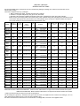
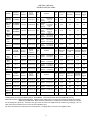
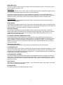
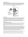
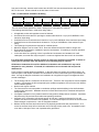
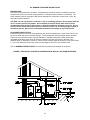
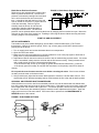
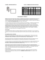
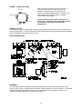
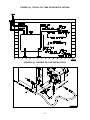
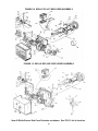
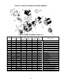
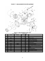
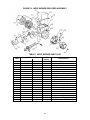
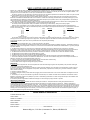
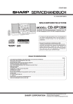
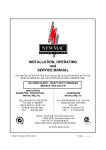
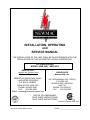
INSTALLATION, OPERATING and SERVICE MANUAL THE INSTALLATION OF THE UNIT SHALL BE IN ACCORDANCE WITH THE REGULATIONS OF THE AUTHORITIES HAVING JURISDICTION. OIL-FIRED BOILER MODEL: NBR-2001 NBR-2002 HEAD OFFICE MARKETING / PRODUCTION Newmac Mfg. Inc. DEBERT AIR INDUSTRIAL PARK, LANCASTER CRESCENT P.O. BOX 9, DEBERT NOVA SCOTIA, BOM 1G0 PHONE: 902-662-3840 FAX: 902-662-2581 EMAIL: [email protected] WAREHOUSE Newmac Mfg. Inc. 430 SPRINGBANK AVE., SOUTH P.O. BOX 545 WOODSTOCK, ONTARIO N4S 7Y5 PHONE: 519-539-6147 FAX: 519-539-0048 NOTICE TO HOMEOWNER: READ THESE INSTRUCTIONS SAVE THESE INSTRUCTIONS 2210150 REVISED APRIL 2007 Subject to change without notice Printed: ________________________ NBR 2001 / NBR 2002 GENERAL INSTRUCTIONS It is the responsibility of the consignee of the unit to examine the package for damage and, if found to note the same on the Carrier’s Bill of Lading The boiler is shipped in three (3) **packages: 1. Boiler complete with casing. Domestic hot water coil is optional. 2. Oil burner **complete with primary relay, photo-cell, and nozzle. 3. Standard control package complete with pressure relief valve; aquastat relay & well; drain valve; tridicator; flexible oil line; burner wiring cable; lockout switch wiring cable; aquastat wiring cable; pipe fittings and instruction manual. A barometric draft regulator may be included in the control package, but is not used on a Newmac Sealed Vent System. The control package is cartooned and shipped inside the boiler crate MODEL NBR-90V NBR2-90V NBR-98V NBR2-98V NBR-111V NBR2111V NBR-90V NBR2-90V NBR-98V NBR2-98V NBR-111V NBR2111V NBR-126V NBR2126V NBR-144V NBR2144V NBR-158V NBR2158V NBR-177 NBR2-177 NBR-91 NBR2-91 NBR-100 NBR2-100 NBR-113 NBR2-113 NBR-127 NBR2-127 NBR-91 NBR2-91 NBR-100 NBR2-100 NBR-113 NBR2-113 NBR-127 NBR2-127 NBR-145 NBR2-145 NBR-160 NBR2-160 NBR-179 NBR2-179 RIELLO BURNERS B.T.U.H. OUTPUT B.T.U.H. INPUT (USGPH) AFUE % BF3 90,000 100,368 (0.72) 85.5 BF3 98,000 108,732 (0.78) 85.2 BF3 111,000 125,460 (0.90) 83.9 BF5 90,000 100,368 (0.72) 85.5 BF5 98,000 108,732 (0.78) 85.2 BF5 111,000 125,460 (0.90) BF5 126,000 BF5 NOZZLE Delavan Hago Delavan Hago 0.60 X 60 B 0.60 X 60 ES 0.65 X 60 B 0.65 X 60 ES Delavan Hago 0.75 X 60 B 0.75 X 60 ES Delavan Hago Delavan Hago 0.60 X 60 B 0.60 X 60 ES 0.65 X 60 B 0.65 X 60 ES 83.9 Delavan Hago 142,188 (1.02) 84.3 144,000 167,280 (1.20) BF5 155,000 BF5 PUMP INSERTION p.s.i. Inches TURBULATOR SETTING AIR SETTING DESIGN GROSS STACK F° 145 3-1/4” 1.5 4.4 300 145 3-1/4” 2 5 320 145 3-1/4” 3 7 375 145 3-1/4” 0.0 3.3 300 145 3-1/4” 0.5 3.6 340 0.75 X 60 B 0.75 X 60 ES 145 3-1/4” 1.5 3.8 375 Delavan Hago 0.85 X 60 B 0.85 X 60 ES 145 3-1/4” 2.0 4.2 410 82.2 Delavan Hago 1.00 X 60 B 1.00 X 60 ES 145 3-1/4” 2.5 4.5 460 184,008 (1.32) 81.6 Delavan Hago 1.10 X 60 B 1.10 X 60 ES 145 3-1/4” 3.5 5 500 177,000 210,494 (1.51) 82.0 3-1/4” 4.0 7.0 550 91,000 101,762 (0.73) 85.8 150 3-1/4” 1.5 3.4 300 40 F3 100,000 111,520 (0.80) 85.3 150 3-1/4” 2.0 3.6 315 40 F3 113,000 128,248 (0.92) 84.1 150 3-1/4” 3.0 4.3 380 40 F3 127,000 144,976 (1.04) 83.9 150 3-1/4” 3.0 5.0 415 40 F5 91,000 101,762 (0.73) 85.8 150 3-1/4” 0.5 1.9 300 40 F5 100,000 111,520 (0.80) 85.3 150 3-1/4” 1.0 2.0 315 40 F5 113,000 128,248 (0.92) 84.1 150 3-1/4” 1.5 2.2 380 40 F5 127,000 144,976 (1.04) 83.9 150 3-1/4” 2.0 2.6 415 40 F5 145,000 170,068 (1.22) 81.9 150 3-1/4” 2.5 2.9 460 40 F5 160,000 188,190 (1.35) 81.8 150 3-1/4” 3.5 3.5 500 40 F5 179,000 213,282 (1.53) 81.4 1.25 X 60 B 1.25 X 60 ES 0.60 X 60 B 0.60 X 60 ES 0.65 X 60 B 0.65 X 60 ES 0.75 X 60 B 0.75 X 60 ES 0.85 X 60 B 0.85 X 60 ES 0.60 X 60 B 0.60 X 60 ES 0.65 X 60 B 0.65 X 60 ES 0.75 X 60 B 0.75 X 60 ES 0.85 X 60 B 0.85 X 60 ES 1.00 X 60 B 1.00 X 60 ES 1.10 X 60 B 1.10 X 60 ES 1.25 X 60 B 1.25 X 60 ES 145 40 F3 Delavan Hago Delavan Hago Delavan Hago Delavan Hago Delavan Hago Delavan Hago Delavan Hago Delavan Hago Delavan Hago Delavan Hago Delavan Hago Delavan Hago 150 3-1/4” 4.0 4.3 560 *Install Beckett Low Firing Rate Baffle (3708) on AFG70MDSS. † Danfoss AS Nozzle with AFG70MBSS Burner only. Model Nomenclature: NBR denotes NBR-2001. Model numbers suffixed with V are approved for Newmac Sealed Vent System. NBR2 denotes NBR-2002. Model numbers suffixed with V are approved for Newmac Sealed Vent System. ** Riello 40 F3 & 40 F5 burners may have air tube in separate box. Use air settings as a guide only. Set burner air to give a trace of smoke. Re-adjust burner air to reduce CO2 reading by 1 to 1.5%. Take measurements with the burner cover & air ducts installed (if any). See burner manufacturer’s instructions for more information. If settings differ, use those on the appliance label 1 NBR 2001 / NBR 2002 GENERAL INSTRUCTIONS MODEL BECKETT BURNERS B.T.U.H. OUTPUT B.T.U.H. INPUT (USGPH) AFUE % NOZZLE 0.65 X 60 B 0.65 X 60 B PUMP INSERTION AIR SHUTTER AIR BAND p.s.i. Inches SETTING SETTING DESIGN GROSS STACK F° AFG70MBSS NBR-96V AFG70MDSS NBR2-96V * 96,000 107,338 (0.77) 87.5 Delavan Hago Danfoss NBR-109V AFG70MBSS NBR2AFG70MDSS 109V * 110,000 124,066 (0.89) 86.2 Delavan Hago Danfoss NBR-122V AFG70MBSS NBR2AFG70MDSS 122V 123,000 140,794 (1.01) 84.8 Delavan Hago Danfoss AFG70MDSS 141,000 164,492 (1.18) 83.1 AFG70MDSS 157,000 184,008 (1.32) 82.2 NBR-171 NBR2-171 AFG70MDSS 172,000 203,524 (1.46) 82.6 MODEL CARLIN BURNERS B.T.U.H. OUTPUT B.T.U.H. INPUT (USGPH) AFUE % EZ-1 121,000 140,794 (1.01) 84.0 Delavan Delavan 0.85 X 60 W 0.85 X 60 B 140 3-1/4” 0.85 / 1.00 0.80 410 EZ-1 139,000 164,492 (1.18) 82.7 Delavan Delavan 1.00 X 60 W 1.00 X 60 B 140 3-1/4” 0.85 / 1.00 1.00 460 EZ-1 152,000 181,220 (1.30) 81.9 Delavan Delavan 1.10 X 60 W 1.10 X 60 B 140 3-1/4” 1.10 / 1.25 1.10 500 EZ-1 171,000 206,312 (1.48) 81.0 Delavan Delavan 1.25 X 60 W 1.25 X 60 B 140 3-1/4” 1.10 / 1.25 1.35 550 AERO BURNERS B.T.U.H. OUTPUT B.T.U.H. INPUT (USGPH) AFUE % NBR-94 NBR2-94 HF-US-2X-5 93,000 104,550 (0.75) 85.4 Delavan 0.75 X 70 B 100 3-1/4” N/A 3/16 300 NBR-105 NBR2-105 HF-US-2X-5 105,000 118,490 (0.85) 84.8 Delavan 0.85 X 70 B 100 3-1/4” N/A 1/4 320 NBR-119 NBR2-119 HF-US-2X-5 122,000 139,400 (1.00) 84.0 Delavan 1.00 X 70 B 100 3-1/4” N/A 3/8 370 NBR-134 NBR2-134 HF-US-2X-5 134,000 153,340 (1.10) 83.5 Delavan 1.10 X 70 B 100 3-1/4” N/A 1/2 390 NBR-151 NBR2-151 HF-US-2X-5 151,000 174,250 (1.25) 82.7 Delavan 1.25 X 70 B 100 3-1/4” N/A 3/4 430 NBR-140V NBR2140V NBR-156V NBR2156V NBR-120V NBR2120V NBR-137V NBR2137V NBR-153V NBR2153V NBR-170 NBR2-170 MODEL Delavan Hago Danfoss Delavan Hago Danfoss Delavan Hago Danfoss 0.65 X 60 AS† 0.75 X 60 B 0.75 X 60 B 0.75 X 60 AS† 0.85 X 60 B 0.85 X 60 B 0.85 X 60 AS† 1.00 X 45 B 1.00 X 45 ES 1.00 X 45 AS 1.00 X 45 B 1.00 X 45 ES 1.00 X 45 AS 1.10 X 45 B 1.10 X 45 ES 1.10 X 45 AS NOZZLE NOZZLE 140 4-1/2” 7.0 0.0 300 140 4-1/2” 9.0 0.0 330 140 4-1/2” 10.0 1.0 360 140 4-1/2” 10.0 1.5 450 175 4-1/2” 10.0 2.0 500 175 4-1/2” 10.0 1.0 540 PUMP INSERTION p.s.i. Inches PUMP INSERTION p.s.i. Inches POSITIONING AIR BAND BAR SETTING TURBULATO R SETTING AIR BAND SETTING inches open DESIGN GROSS STACK F° DESIGN GROSS STACK F° *Install Beckett Low Firing Rate Baffle (3708) on AFG70MDSS. † Danfoss AS Nozzle with AFG70MBSS Burner only. Model Nomenclature: NBR denotes NBR-2001. Model numbers suffixed with V are approved for Newmac Sealed Vent System. NBR2 denotes NBR-2002. Model numbers suffixed with V are approved for Newmac Sealed Vent System. Use air settings as a guide only. Set burner air to give a trace of smoke. Re-adjust burner air to reduce CO2 reading by 1 to 1.5%. Take measurements with the burner cover & air ducts installed (if any). See burner manufacturer’s instructions for more information. If settings differ, use those on the appliance label. 2 BOILER INSTALLATION INSTALLATION REGULATIONS This unit should be installed in accordance with the regulations of the authority having jurisdiction. In Canada the installation must conform to CSA Standard B139, "The Installation Code for Oil Burning Equipment." In the United States, the National Fire Protection Association Standard NFPA 31 should be followed. Check with provincial, state, or local codes concerning clearances, venting system requirements and other regulations governing installation. Some codes may vary from the requirements set forth in this manual. FOUNDATION To ensure the boiler is on a level foundation and above any possible dampness, a cement pad is recommended. CLEARANCES The minimum clearances to combustible construction are as follows: 6" Side: 6” Top: 6” Rear: 6” Front: 24" Flue Pipe: 9" Approved Floor Type: Combustible Allow sufficient room for servicing. FOR YOUR SAFETY: Do not store or use gasoline or flammable vapors and liquids in the vicinity of this or any other appliance. VENTING PRODUCTS OF COMBUSTION Chimneys The required minimum flue pressure is -0.02 inches of water column. The required minimum overfire pressure is -0.005 inches of water column. Locate the boiler as close to the chimney or flue as possible. The maximum draft is obtained by keeping elbows and pipe length to a minimum. Install the flue pipe with a gradual rise of at least 1/4" per foot from the boiler to the flue. Do not extend the flue pipe beyond the inside wall of the chimney. Refer to Table 8 (a) and Table 8 (b) for proper sizing and Figure 19 for optimizing chimney draft. The owner shall provide a chimney constructed to comply with the following specifications: (a) The chimney must be absolutely smoke tight throughout its entire length, and must extend at least three feet (3') above a flat roof or two feet above the ridges of peak roofs. (b) If built of a single thickness of brick or of cement blocks, it shall be lined throughout its entire length with fire clay lining, having not less than three-fourths inch (3/4") thickness. Flue lining is to be laid in mortar and made air tight. If the chimney is of the prefabricated type, it must be an approved class "A" chimney or type "L" Vent for interior. (c) The boiler flue must have no other openings for attaching any fireplace, stove, range, gas or ventilating connection unless the equipment is appropriately certified. (d) If it is necessary to offset the flue, it must be done in such a manner as not to reduce the gross crosssectional area or create a ledge or obstruction, where loose material may lodge. (e) Flue pipe connections must be secured with metal screws. CAUTION: Oil-fired appliances shall be connected to flues or vents having sufficient draft at all times to ensure safe and proper operation of the appliance. Barometric Draft Regulator The Listed/Certified draft regulator must be installed between the appliance and the chimney, within easy reach for adjustment and free from obstruction. Use larger or multiple draft regulators for chimneys with strong draft. Follow the draft regulator manufacturer's instructions for proper installation. Power Venting Consult installation codes for requirements and approvals governing power venters and draft inducers. Follow the instructions supplied with them for proper installation. 3 Newmac Sealed Vent System Consult the GENERAL INSTRUCTIONS of this manual for approved burners. Follow the instructions supplied with the SVS system for proper installation. PIPING Locate the boiler as close as possible to the center of the heat distribution system and make sure the top is level. Typical Piping Layouts are shown in Figure 10 and Figure 11. Radiant Floor Piping Only pipe certified for in floor applications should be used. Cross-linked polyethylene (PEX) pipe with the ASTM F876 designation is widely used. Polybutylene (Poly B) has a lower temperature and pressure rating than PEX and is more susceptible to kinking. Non-metallic pipes must have an oxygen diffusion barrier to prevent oxygen molecules from passing through their walls. Oxygen entering the hydronic system may cause degradation of the components. AIR PURGE Air in water at normal atmospheric conditions promotes corrosion. Since corrosion is a chemical reaction and chemical reactions increase with temperature, at boiler operating temperatures the corrosion factor must not be overlooked. Air can also cause noise and circulation problems. Once in operation and purged of air the only source of new air should be the makeup water. Automatic air vents placed at high points in the piping system usually will relieve this problem. Installation of a microbubble resorber air eliminator (Spirovent) in the supply line is highly recommended. Chemical Additives A corrosion inhibitor is required to further guard against oxygen in the system and growth of anaerobic bacteria. Glycol should only be used if the possibility of freezing exists--a non-toxic propylene glycol must be used. Glycol significantly decreases the system efficiency, therefore the minimum amount should be used. ELECTRICAL CONNECTIONS Standard boiler models are rated at 120 V, 60 Hz, 1-Phase, 15 Amp Fuse. Other voltages are available. Refer to the certification label prior to making electrical connections. Follow the National Electrical Code as well as provincial, state, and local regulations. Figure 12 shows a standard wiring schematic. WARNING: Make sure the electrical lockout switch is operating properly. Power to the burner should be interrupted when the front access cover is opened or removed. THERMOSTAT The thermostat should be located on an interior wall free from drafts approximately 5 feet above floor level. The operation of the burner is normally controlled by the room thermostat, which may be set for the temperature desired, typically 70 F. If a higher or lower temperature is desired, the indicator should be set to the proper point on the scale. To shut down the burner at any time, turn the main power switch off. To prevent short cycling, the heat anticipator must be set at 0.2 amps as indicated in Figure 1. This adjustment shuts the burner down to prevent the room temperature from exceeding the thermostat setting. FIGURE 1 Heat Anticipator WARNING: The heat anticipator will BURN OUT if 25 volts are applied directly to the thermostat by shorting out the primary control during testing or incorrect wiring. If this happens the thermostat warranty is void. 4 GAUGES The pressure and temperature gauge supplied with the boiler has a 1/4” NPT connection. Refer to Figure 9 for its location. TANKLESS DOMESTIC HOT WATER COIL For boilers equipped with tankless coils, installing the aquastat in the top tapping is not recommended. Mounting the aquastat on the coil plate allows the burner to respond faster to flow through the tankless coil increases the availability of domestic hot water. In area where hard water may be a problem, a water softener is recommended. Mineral deposits will reduce heat transfer and restrict flow. An indirect storage tank is recommended if high consumption of domestic hot water is anticipated. BACKFLOW PREVENTER To prevent contamination of potable water a backflow preventer is required. Be sure the inlet side is connected to the domestic water supply. Do not use a single check valve for this purpose. FLOW CHECK VALVES Use a flow check to prevent thermal siphoning or gravity flow when the circulator is off. Pump differential is required to open the valve. Observe flow direction when installing these valves. PRESSURE RELIEF VALVE A 30 p.s.i pressure relieve valve is supplied with the appliance to protect against excessive water pressure caused by thermal expansion of the water or emergency steam conditions caused by runaway overfiring. It has 3/4” NPT for connection to the top (highest point) of the boiler. Refer to Figure 9 for its location. Orient the valve vertically and so that blow off is directed out of harms way. To avoid water damage, a drain pipe of the same size as the valve outlet can be connected --it must be pitched down. An occasional drip from the valve is normal. Do not install a shut off valve between the outlet and disposal site. The blowdown pipe should terminate about six inches from the floor for unrestricted flow, preferably near a floor drain. Replacement valves should have the same rating as the original one and be ASME approved. Relief valves are rated according to B.T.U.H. LOW WATER CUT-OFF Some jurisdictions may require a safety control to guard against low water situations. A ¾ NPT tapping is provided to mount this control directly on the boiler PRESSURE REGULATING VALVE A pressure regulating valve is not part of the standard controls package. Since local regulations may require installation of this type of valve they are available as an option from Newmac. The function of this control valve is to regulate the boiler feed water to 12 or 15 psig to compensate for the water main working pressure which may be excessive. For convenience these valves incorporate an internal bypass for fast filling and air purging of the system. It must be mounted in a horizontal position in the cold water supply upstream from a shut-off valve. Be sure the flow direction arrow is pointing toward the system. EXPANSION TANK Water expands as it is heated. Normal operation requires the boiler and piping to be full of water. As the water is heated an airtight tank located above the boiler provides a place for the additional volume of water to go. With a compression tank air trapped in the system will migrate to the upper part of the tank above the water level. The tank should be sized based on the boiler output rating and the water capacity of the system. AQUASTAT CONTROL This control has a probe mounted in a well and immersed in the boiler water to sense temperature. It is thermally operated with three settings to regulate boiler water temperature for space heating equipment and domestic hot water service. The operation of the Honeywell control as shown in Figure 2 is discussed here. Refer to Figure 9 for its location. High Limit Setting: This setting regulates burner operation. When the high limit setting is reached on temperature rise dangerous overheating of the boiler is prevented by cutting power to the burner. The temperature has to fall by 10 F before power is restored . Note: The high limit must be set at least 20 F higher than the low limit setting. 5 Low Limit Setting: This setting controls the minimum standby temperature. It regulates circulator and burner operation. When the low limit setting is reached as the boiler water temperature increases the burner circuit breaks and the pump starts circulation of hot water. The circulator continues to operate to satisfy the call for heat from the thermostat until the water temperature falls 10 F below the set point. The burner circuit makes when the water temperature falls 10 F below the low limit set point. Differential Setting: This setting only effects the low limit operation. The circulator make and burner break temperature can be elevated by raising this setting. This temperature will be the set point temperature plus the difference between the differential setting and 10 F. The differential setting does not change the burner make and circulator break temperature. The recommended aquastat settings are as follows: HI 180 LO 160 DIFF 20 Aquastat Control Operating Sequence with Room Thermostat Calling: The burner starts if the boiler water temperature is less than 170 F. With the low limit set at 160 and the differential set at 20 F, the circulator starts on a temperature rise at 170 F. The circulator runs distributing hot water through the system until the temperature falls to 150 F. When the high limit setting of 180 F is reached the burner shuts off. The burner will restart as the temperature falls by 10 F to 170 F. Aquastat Control Operating Sequence with Room Thermostat not Calling: With the low limit set at 160 and the differential set at 20 F the burner shuts off at 170 (low limit setting minus 10 F plus the differential setting). The burner restarts when the boiler water temperature falls below 150 F (low limit setting minus 10 F). FIGURE 2 Honeywell L8124L. OPTIONAL AQUASTAT CONTROLS The Honeywell L7124U Electronic Aquastat is approved as an alternate control. White Rodgers 8B43A601 is certified. Honeywell L6006A and L4006A can also be used. CIRCULATOR Flush the system to remove foreign matter. Operate the circulator for 5 minutes immediately after filling the system to purge air pockets. 6 MIXING METHODS A method of mixing is required for boiler protection with low temperature systems. The minimum return water temperature required is 135 F. Mixing Valves A three-way mixing valve can be used in most conventional systems such as baseboard radiation as long as a minimum return water temperature of 135 F can be maintained. A four-way mixing valve is commonly used for radiant floor applications. This will allow blending to maintain the relatively high boiler loop temperatures while sustaining the lower temperatures required for radiant floor heating. Most mixing valves can be controlled manually or with an automatic motor. Injection Systems Controls for mixing using variable speed injection pumps, on/off injection pumps and on/off injection valves are readily available. ZONE VALVES Conventional zone valves operate in either a fully open or fully closed position. Most are normally closed until the thermostat calls for heat. Some models have an end switch that activates the circulator when the valve is fully open. Some newer valves are designed to modulate flow. ANTI-SCALD VALVES An automatic thermostatically controlled tempering valve is required to prevent scalds. It should be located approximately 10 inches below the domestic hot water supply outlet. This will keep the valves bimetallic thermostat element from sensing non-flowing hot water. Manually operated valves are not suitable for use as anti-scald valves. HOT WATER EXTENDER TEMPERING VALVES A good quality valve is recommended to mix the domestic hot water supplied by the tankless coil or indirect storage tank with the cold water supply to produce a comfortable temperature. The ability of the valve to maintain a constant temperature is proportional to the quality of the valve. The valve must be installed according to the valve manufacturer’s instructions with a suitable balancing valve and thermal heat trap if specified. DHW BALANCING VALVE A modulating type valve should be used to achieve the desired blend of hot and cold water. FLOW RESTRICTOR A flow restrictor valve is often used for constant flow, energy conservation and water management. These valves are useful where high temperature is required and flow rate can be reduced. Flow restrictors are available that are designed for tankless heater applications. For systems with pressures exceeding 50 psi it is good practice to install a flow restrictor. OUTDOOR RESET CONTROL This control adjusts the water temperature supplied to the distribution system according to the required heating load. The supply water is controlled automatically based on the correlation between the required supply water temperature and actual outdoor temperature. Boiler outdoor reset should not be used is a tankless coil is used. GATE VALVES Gate valves are designed for component isolation. They should be fully open or fully closed. A ball valve can be used as a lower cost alternative. GLOBE VALVES Flow regulation can be accomplished with globe valves. 7 BLOCKED VENT SWITCH The WMO-1 blocked vent control is required on Newmac oil-fired and combination furnaces or boilers installed in Canada. The WMO-1 switch must be installed on the chimney vent pipe for Newmac oil fired furnaces and boilers; and installed on the burner plate for Newmac combination wood/oil or coal/oil fired furnaces. Do not use the WMO-1 Blocked Vent Switch with the Newmac Sealed Vent System (SVS). Refer to the Newmac and Field Controls Instructions enclosed in the WMO-1 package. Wiring WMO-1 WMO-1 Limit N Primary Control T T F F Cad Cell Connect WMO-1 at appliance junction box (except CL series) Motor CL series combination furnaces: Connect WMO-1 at the burner control junction box Ignition Burner FUEL SYSTEMS Fuel not heavier than No. 2 fuel oil must be used. The oil tank must be of an approved type--ULC labeled in Canada and ULI labeled in the United States. Install the oil storage tank or tanks according to local codes and regulations. The supply tank should be kept at least 1/4 full. Suction and return lines should be of the same diameter and extend to the same depth in the tank. An emergency oil shut-off valve should be installed as required by local ordinance. This can be manual, electric solenoid, or vacuum operated. An oil safety valve that cuts the fuel supply unless a vacuum is created by the pump is recommended. Any leaks in the system will prevent oil from flowing. Suntec PRV or Webster OSV valves are recommended. COMBUSTION AND VENTILATION AIR Free air for combustion and ventilation must be permanently provided to the boiler room. Combustion air refers to the total air requirements of the fuel burning appliance. This includes air for the combustion process and air to provide chimney draft (dilution air). Ventilation air ensures free circulation of air in the room where the appliance is located to keep ambient temperatures within safe limits under normal conditions. Boilers installed in tight houses, in houses with unbalanced air flows, or in enclosed spaces are very likely to have homeowners complain of smoke, fumes, burner lockouts, and excessive fuel consumption. This is more prevalent in post 1985 construction due to the tighter building construction as prescribed by the latest building codes. Regulations are relatively specific on the minimum allowable quantities of ventilation and combustion air required once the space category is determined. However, every house is subjected to different internal and external conditions and regulations vary among localities. With this in mind, Newmac requires provision for combustion and ventilation air as specified in Table 1. Table 1 is based on; relevant codes and regulations, assumptions, generalizations, and simplifications. Values indicated in Table 1 are based on the maximum input rating. However, in making combustion and ventilation analysis the aggregate input rating of all appliances in the space must be considered. The installation of additional oil-fired appliances may require more combustion and ventilation air. Allowances must also be made for the blocking effect of louvers, grilles and screens. If the design and 8 free area is unknown, assume wood louvers have 20-25% free area and metal louvers and grilles have 60-75% free area. Screens should not be less than 1/4 inch mesh. Table 1 Combustion & Ventilation Air Sizing FLOOR AREA (Square feet) SPACE CATEGORY more than 1,150 1,150 or less Unconfined Confined Vertical Ducts & Direct Opening Sizes Free Area L X W (QTY) Dia. (QTY) (in.2) (in. X in.) (in.) 37 6 X 6 (1) 7 (1) 92 6 X 8 (2) 8 (2) Horizontal Duct Sizes (in.) Free Area L X W (QTY) Dia. (QTY) (in.2) (in. X in.) (in.) 37 6 X 6 (1) 7 (1) 184 8 X 12 (2) 11 (2) The free area of ducts specified in Table 1 assume air is conveyed from outdoors. The following should be kept in mind when using Table 1: All applicable codes and regulations must be followed. Unconfined free area values for openings to outdoors are based on 1 sq in per 5,000 Btu/hr of the maximum input rating. Confined free area of vertical ducts is based on 1 sq in per 4,000 Btu/hr of the maximum input rating. Confined free area of horizontal ducts is based on 1 sq in per 2,000 Btu/hr of the maximum input rating. Two openings of equal size are required for confined spaces. Maximum length of run for ducts is 50 ft. Duct size allowances must be made for longer runs. Ducts should be designed or insulated to prevent condensation. If insulating, a minimum insulation value of R-3 is required. In the case where one opening or duct is specified and combustion and ventilation air is still inadequate, a second duct may be required. Locate one high and the other low for air circulation. It is particularly important to duct the cold air as close to the appliance as possible. A means of closing the air openings when the appliance is not operating may be required. Guidelines to determine the need for additional combustion and ventilation air may not be adequate for every situation. If in doubt, it is advisable to err on the safe side and provide additional air. Figure 3 shows a typical appliance installation. In this case there is a furnace and a water heater in an enclosed space--both require ventilation and combustion air which is delivered by the top and bottom air ducts. As long as adequate combustion and ventilation air is supplied, this type of arrangement offers several advantages: The incoming cold air is confined to the furnace room. Therefore, the occupants are less susceptible to drafts. Cool outdoor air will be tempered by the ambient temperature of the furnace room before it enters habitable spaces. Noise levels may be reduced. The furnace will be less susceptible to combustion spillage and backdrafting in low draft situations reducing odor and smoke. Moderate amounts of smoke and fumes will be contained and expelled safely outdoors. Incomplete combustion of any carbon based fuel may produce deadly carbon monoxide. Ventilation may dilute any CO produced under abnormal operating conditions. Adequate air for combustion will yield the proper air fuel ratio. Appliances burning fuel rich will produce soot and burn excessive fuel quantities. A 1/8 inch thick deposit of soot on the surface of the heat exchanger is equivalent to 1 inch of fiberglass insulation. Modern efficient furnaces and boilers tend to be physically smaller than their predecessors. As a result, hot surfaces such as flue connectors are not as high as they used to be. A separate furnace room with a “child proof” door is an important safety precaution. 9 OIL BURNER OPERATING INSTRUCTIONS BURNER CARE This burner is fully automatic in operation. All adjustments should be made by a qualified technician. Keep the burner free from excess dirt and moisture. Oil leaks should be tended to immediately. The motor should be given a few drops of SAE 20 non-detergent oil at least two or three times a year. No other parts require lubrication. CAUTION: Do not use gasoline, crankcase or any oil containing gasoline. Do not tamper with the unit or controls--call the serviceman. Do not attempt to start the burner when excess oil has accumulated, when the unit is full of vapor or when the combustion chamber is very hot. Do not start the burner unless the cleanout doors are secured in place. Do not burn garbage or paper in the heating system. Never leave combustible materials such as paper or rags near the unit. OIL BURNER INSTALLATION Install the oil nozzle in the burner firing assembly, and check the adjustments. Figure 5 and Table 2 can be used to obtain the correct electrode settings. These settings are critical for proper burner operation. Some burner manufacturers have a gauge available for setting the electrodes. Most burners with adjustable heads have preset stops to ensure the distance from the nozzle face to the face of the retention head (“Z” dimension) is correct. Set the air tube insertion depth according to Figure 6 and Table 2. This is the distance from the face of the mounting flange to the face of the retention head. Use the GENERAL INSTRUCTIONS in this manual for preliminary air settings for the burner. FIGURE 3 APPLIANCE LOCATED IN CONFINED SPACE WITH ALL AIR FROM OUTDOORS 10 Riello Burner End Cone Protector FIGURE 4 Riello Burner End cone Protector Riello burners are equipped with a ceramic fibre sleeve to protect the end cone. The end cone protector is mounted by rotating it back and forth as it is slid over the burner end cone and air tube. It should be flush with the face of the end cone or extend no more than ¼” beyond the end of the tube assembly. Refer to Figure 4. Carefully insert the burner air tube into the combustion chamber without damaging or moving the ceramic sleeve. The end cone protector can be replaced without removing the burner by swinging the front smoke box open. Mount the oil burner on the 4 lugs of the smoke box. Installing or removing the burner without removing the burner mounting flange is not recommended. START-UP AND ADJUSTMENT SET-UP INSTRUMENTS The installer must use a suitable draft gauge, smoke tester, carbon dioxide tester, 0-750 F stack thermometer, 0-200 psi oil pressure gauge, 0-30 in. Hg. vacuum gauge, and 0-220 F thermometer to properly set-up the burner. 1. Turn on supply power and set the thermostat above room temperature. 2. Open all oil lines and valves. 3. Make sure the oil pump by-pass plug is correctly located for a one or two pipe system. Bleed the oil pump (refer to pump manufacture's instructions). 4. Adjust the air band on the burner until a #1 smoke or less is reached using a smoke tester. If a smoke tester is unavailable, slowly close the air band until the fire becomes smoky. Slowly increase the air until a small amount of smoke is observed at the flame tips. - If the unit fails to start, check: (a) oil supply; (b) ignition electrodes and transformer; (c) cad cell. - If the burner goes off on safety, do not push the reset button on the primary control for at least 10 minutes. Do not push the reset button more than once before correcting the cause. If the burner still does not start, press the reset on the burner motor. 5. Using a draft meter, adjust the barometric draft regulator to measure -0.02 inch water column. This requires that a 5/16" diameter sampling hole be made between the flue collar and the draft regulator. SEASONAL OR EXTENDED SHUT DOWN PERIODS When the burner is not to be used for an extended period of time, set the thermostat at its lowest value, turn off the main switch and close the oil burner supply valve. If the heating unit room is damp, protect the burner against dirt and moisture with a light cover. To resume operation, remove the cover and inspect the burner. Remove any dirt and debris gently to avoid the need to adjustment the air band. Open the supply valve and turn on the main switch. If the burner fails to operate see the MAINTENANCE & SERVICE section of this manual. FIGURE 5 ELECTRODE SETTINGS 11 FIGURE 6 BURNER INSERTION TABLE 2 DIMENSIONAL RELATIONSHIPS E Riello Beckett AFG Aero Carlin HF-US EZ-1 5/32" 1/8" 1/8" to 5/32" 7/16" 7/32" 5/16" 1/16" 1/16" 1/8" 1/16" Z Refer to Turbulator Setting 1-3/8" 1-3/4" 1-1/8" Use Positioning Bar E 3-1/4" 4-1/2" 4-1/2" 3-1/4" 3-1/4" F3 F5 BF3 BF5 MB MD A 5/32" 5/32" B 13/64" 7/16" C 5/64" to 7/64" MAINTENANCE & SERVICE Maintenance and servicing must be done by a qualified burner technician or shortened boiler life and poor efficiency may result. Under Tests and Observations and Requirements in CSA B139, the installer is required to perform tests to ensure proper and safe operating conditions. Newmac requires the installer to fill out the INSTALLER INFORMATION sheet found in this manual. The heat exchanger and firetubes should be inspected on an annual basis. If cleaning is required, open or remove smoke boxes--take care not to break the ceramic liners or gaskets. Use a wire brush (available from Newmac) to loosen scale and soot and a vacuum cleaner to remove it from the boiler. Replace gaskets if necessary before closing or replacing the smoke boxes. A layer of soot on the heat exchanger surfaces and firetube walls will reduce heat transfer and can increase fuel consumption significantly. A 1/32” layer of soot acts as an insulator and can result in a 3% increase in oil burned. Likewise a 1/16” layer may result in an average fuel loss of 8%. OIL FILTER The oil filter should be cleaned or replaced at least once a year by the serviceman. Use a 10 micron or better filter. We recommend General Filters Model GF-CGF10 (refill GF-K10GF) or Garber Model 11BVR. OIL PUMPS & FUEL SYSTEMS Make sure the by-pass plug is correctlly located for a one or two pipe system. Failure to do so may damage the pump. Generally, for 3/8” copper tubing the vertical lift should not exceed 8 feet and the horizontal run should be limited to 30 feet. Do not exceed 10 p.s.i. inlet line pressure. Single pipe systems are recommended for gravity feed or when the tank outlet is at a higher elevation than the pump inlet. Refer to Figure 8 (a). The inlet vacuum should be no more than 6" Hg. Two pipe systems are recommended for lift feed or when the pump inlet is at a higher elevation than the tank outlet. Install the return line termination higher than the supply intake as shown in Figure 8 (a). Generally, the inlet vacuum should be no more than 12" Hg. Correct piping is critical to long-term operation of the fuel system. Never use compression fittings. Minimize the resistance to flow due to excessive line lengths; high lift; and unnecessary fittings, kinks and bends. This will decrease the running vacuum and the risk of air seperation. A “Tigerloop” fuel oil deaerator may improve the performance of poorly designed fuel oil delivery systems. Pressure Check Install the pressure gauge directly on the gauge or nozzle port. Adjust to the pressure specified by Newmac for the nozzle input rating. Refer to the GENERAL INSTRUCTIONS in this manual or the certification label. 12 FIGURE 7 TYPICAL OIL PUMP GAUGE PORT NOZZLE PORT INLET PORT BLEED PORT INLET PORT RETURN & BY-PASS PORT Each oil burner should have its own suction line. A common return line can be used as long as the diameter is large enough. Check valves are not required on properly installed systems. Service on fuel units should not be attempted without a suitable vacuum and pressure gage. The information presented here is intended as a guide only. For piping system design data, consult the installation instructions from the pump manufacturer. FLEXIBLE OIL LINE The flexible oil supply line shipped with the boiler must be installed between the oil pump and the oil line from the storage tank. For a two pipe system a similar flexible return line is required and may be obtained from your distributor. See Figures 8 (a) and 8 (b). FRONT ACCESS DOOR WARRANTY The following information is required to process warranty claims, owner’s name and address; serial number; model number; installation date; and name, address and phone number of installer. A “Returned Goods Number” must be issued by Newmac prior to acceptance of returned goods. Refer to your LIMITED LIFETIME WARRANTY for terms and conditions. 13 FIGURE 8 (a) TYPICAL OIL TANK PIPING INSTALLATIONS FIGURE 8 (b) FLEXIBLE OIL LINE INSTALLATION 14 FIGURE 9 DIMENSIONS & CONTROL LOCATION 15 FIGURE 10 TYPICAL PIPING LAYOUT 16 FIGURE 11 TYPICAL RADIANT FLOOR PIPING LAYOUT 17 FIGURE 12 (a) STANDARD WIRING SCHEMATIC – Riello & Carlin 18 FIGURE 12 (b) STANDARD WIRING SCHEMATIC – Beckett & Aero 19 20 FIGURE 13 NBR 2001 EXPLODED ASSEMBLY TABLE 3 NBR-2001 / NBR-2002 PARTS LIST Item NBR-2001 Part NBR-2002 Part No. No. Description 1A 1B 4110194A 4110194 4110220 3/16" Pressure Vessel Assembly 1/4" Pressure Vessel Assembly 2 3100219 3100219 Fire Tube 3 4110198 4110198 Front Smoke Box 4 2030192 2030192 Smoke Box Liner – Front 5 2080078 2080078 Smoke Box Gasket ( 76-1/2" Long) 6 4110199 4110199 Rear Smoke Box 7 2030193 2030193 Smoke Box Liner – Rear 8 4110197 4110223 Casing – Top 9 4110195 4110221 Casing - Right Side 10 4110196 4110222 Casing - Left Side 11 4060240 4060240 Combustion Tube SS Insert 12 4110190 4110190 Smoke Box Brackets 13 2080044 14 2190047-J 15 4110182 16 3070002 3070005 Insulation, Fiberglass 17 4050207 4050207 Burner / Lockout Switch Cable 18 4050203 4050203 Aquastat / Lockout Switch Cable - 4 Wire 19 4050193 4050193 Aquastat / Circulator Cable - 3 Wire 20 2190067 2190067 Burner Lockout Switch 21 4110191 4110191 Lockout Switch Junction Box Cover 22 4110192 4110192 Lockout Switch Junction Box 23 4110205 4110205 Smoke Box Hinge 24 3100227 3100227 Hinge Pin 25 4110189 26 2190068 2190068 Flexible Oil Line * 27 2190071 2190071 Flexible Oil Line to Pump Adapter * 28 2190070 2190070 Flexible Oil Line to Tube Adapter * 29 2130036 2130036 Sight Glass Retainer 30 2080061 2080061 Sight Glass 31 2080060 2080060 Sight Glass Gasket 32 2010028 2010028 Aquastat - Honeywell L8124L * 33 A 2010049 2010049 Aquastat Well, Honeywell 123870AB * (NBR2001 Less Coil and NBR2002) 33 B 2010029 34 2190085 2190085 Tridicator * 35 2190004 2190004 Pressure Relief Valve, 3/4 FPT X 3/4" FPT * 36 3100244 3100244 Firetube Baffle 37 A 5400009PP 5400009PP 37 B 5400007 5400007 Oil Burner - Riello F5 37 C 2110050 2110050 Oil Burner - Beckett AFG70MDSS, NM802 37 D 5400034 5400034 Oil Burner – Beckett AFG70MDSS c/w pre & post purge, NM804 37 E 2110164 2110164 Oil Burner - Carlin EZ-1, 9785700BNBR2 37 F 5400057 5400057 Oil Burner - Carlin EZ-1 c/w pre & post purge 37 G 2110156 2110156 Oil Burner - Aero HF-US-2X-5 2170010 2170010 Cleanout Brush 2190004 2190004 Pressure Regulating Valve, 1/2" NPT Threaded Coupling X 1/2" NPT 2060005 2060005 Circulator, Grundfoss, UP 15-42F, 1 Spd, 50628206J2 2060006 2060006 Circulator Flange Kit, Grundfoss, Cast Iron, 519603 2190007 2190007 Zone Valve 2010008 2010008 Thermostat 2010057 2010057 Thermostat - White Rodgers 1F30 2010080 2010080 Digital Thermostat (Mercury Free) - Erie T201C 5010132 5010132 Standard Control Package (NBR2001 Less Coil and NBR2002) 5010133 Standard Control Package (NBR2001 c/w Coil) 2210150 2210150 Service Manual * 2190063 2190063 1/2" Drain Valve 2190073 2190073 Reducer Bushing, 1-1/4" MPT X 1/2" FPT 2190062 2190062 3/4" X 4" Pipe Nipple * 2190038 2190038 3/4" NPT BI Plug * 2190074 2190074 1-1/4" NPT BI Plug * 2010062 2010062 Surface Strap-on High Limit Control, White-Rodgers 1127-2 2040019 2040019 5" Barometric Draft Regulator Coil Flange Gasket Domestic Hot Water Coil - 5 GPM Coil Plate Coil Drip Tray Aquastat Well, Honeywell 123871AB * (NBR2001 c/w Coill) Oil Burner - Riello BF5 c/w post purge These items are included in the Standard Control Package 21 FIGURE 14 RIELLO F3 & F5 EXPLODED ASSEMBLY FIGURE 15 RIELLO BF3 & BF5 EXPLODED ASSEMBLY Item 49 Riello Burner End Cone Protector not shown. See FIG 13 for its location. 22 TABLE 4 RIELLO BURNER PARTS LIST ITEM F3 & F5 PART NUMBER BF3 & BF5 1 2 1 1 3 3 4 5 6 8 10 11 12 13 14 15 16 17 18 19 20 21 22 23 24 25 26 27 28 29 30 32 33 34 35 36 38 40 41 42 43 44 45 46 47 48 2 4 6 7 8 9 10 11 12 13 20 14 15 16 17 18 19 22 21 24 25 5 32 32 33 34 40 40 41 41 42 43 44 44 45 45 46 46 47 48 48 3 23 26 26 27 29 30 31 35 36 37 49 RIELLO 3007232 3007233 3008019 3008023 3006992 3006571 3006993 3005847 3007077 3007028 C7010002 3005719 3006925 3007203 3007029 3007156 3007268 3007087 3002278 3006553 3002279 3007802 3000443 3005843 3007315 3007316 3002280 C7001029 3005854 3000932 3005856 N/A 3000878 3007204 3007207 3007208 3007824 3005844 3005708 3007221 3007222 3948873 3948973 3006968 3006977 3006966 3006965 3006969 3006973 3006324 3006323 3006330 3006329 3005869 3007592 3007594 3007568 C5283000 3008020 3008024 3007901 3007630 3000681 3008021 3007707 3007628 3007627 C7001025 C7001026 NEWMAC BURNER MODEL F3 F5 BF3 DESCRIPTION BF5 X X X X 2090043 2060007 2020018 2010045 2010048 2080058 X X X X X X X X X X X X X X X X X X X X X X X X X X X X X X X X X X X X X X X X X X X X X X X X X X X X X X X X X X X X X X X X X X X X X X X X X X X X X X X X X X X X X X X X X X X X X X X X X X X X X 2090041 X X X 2210141 2210143 X X X X X X X X X X X X X X X X X X X X X X X X X X X X X X X X X X X X X X X X X 2110172 2110173 2030016 X X X X X X X X X X X X X 23 X X X X X X X X X X X X X X X X Burner back cover Burner back cover Burner cover Burner cover Pipe connector-supply 3/8" NPT/metric adapter-male Pipe connector-return ¼" NPT/metric adapter-female Crushable metal washer 3/8" ID O-ring - pump pressure regulator O-ring - pump cover Pump screen Valve stem Plate - valve stem retainer O-ring valve stem,upper O-ring valve stem,lower Nozzle outlet fitting Crushable metal washer 5/8" ID Primary control sub-base Coil U-bracket retainer nut Coil Pump Pump drive key Motor Air tube cover plate Air tube cover plate Photo cell Primary control 530 SE/C Semiflange (2 Req'd) Adjustable mounting flange Mounting gasket Regulator Hydraulic air shutter Manual Air Shutter Air intake housing Air intake housing Air intake housing Capacitor 12.5 uF Fan Chassis front plate Air intake housing Short combustion head - 6" Short combustion head - 6" Turbulator disc Turbulator disc Electrode support Nozzle adapter Nozzle oil tube - short Nozzle oil tube - short Regulator assembly - short Regulator assembly - short Electrode assembly - short Electrode assembly - short Electrode porcelain End cone assembly - short End cone assembly - short Bleeder Electrical fitting Oil supply tube & adapter fitting Oil supply tube & adapter fitting Plug Gasket burner cover Manual air damper regulator Air damper Cover screw and washer Filter assembly Plug-cover opening-burner reset Two line conversion kit Two line conversion kit End Cone Protector, Ceramic Fibre FIGURE 16 BECKETT BURNER EXPLODED ASSEMBLY TABLE 5 BECKETT BURNER PARTS LIST ITEM PART NUMBER BECKETT NEWMAC 1 5877 2 3709 4198 3492 3493 5941 21805U 2999 2454 21844U 2256 5636 51771U 3708 3 4 7 9 10 11 12 13 14 17 18 21 27 28 36 47 48 48 49 5770 21877U 2-13 1-49 3384 3383P 5913 5912 58020002 580571 7456U 21755U 7006 2090024 BURNER MODEL AFG70MBSS AFG70MDSS NM801 NM803 NM802 NM804 X X X X X X X X X X X X X 2020019 2090056 2090011 2060012 X X X X X X 2090064 2090044 X X 2090072 X X X X X X X X X X X X X X X X X X X X X X X X X X X 2110014 X X X X X 2090062 2090069 2090067 2090065 2010006 X X X X X X X X X X 24 X X X DESCRIPTION Burner Housing Assembly Air Shutter Retaining Screws Air Band Escutcheon Plate Adjusting Plate Assembly PSC Drive Motor Blower Wheel Coupling Pump (Clean Cut A2EA – 6520) Pump Nozzle Port Fitting Connector Tube Assembly Electronic Ignitor Low Firing Rate Baffle Electrode Assembly Junction Box Kit Valve Stem (Clean Cut) Nozzle Adapter – Single Electrode Clamp 3-3/8U Static Plate 2-3/4U Static Plate Burner Head, Type V1 Burner Head, Type L1 7" SS Air Tube c/w Welded Flange (4.5”) 7" SS Air Tube c/w Welded Flange (4.5”) Primary Relay, Honeywell R7184B Primary Relay, Honeywell R7184P Valve Coil Cad Cell C554A1455B Honeywell FIGURE 17 CARLIN BURNER EXPLODED ASSEMBLY TABLE 6 CARLIN BURNER PARTS LIST ITEM 1 2 3 4 5 7 7 8 9 10 11 12 13 PART NUMBER CARLIN NEWMAC 9785700BNBR2 2110164 9785732J137V 2110165 9786101 98022 41000SOCAS 40200-02 60200-02 27813 98304 34397 34470 75564 77594 77586 81570 4015300K 81695 77933 2060004 2090058 BURNER MODEL EZ-1 EZ-1 PP X X X X X X X X X X X X X X X X X X X X X X X X X X X X X X X 25 DESCRIPTION EZ-1 Burner EZ-1 Burner c/w pre & post purge 7" Air Tube c/w Welded Flange Motor, PSC, 1/6 HP Electrode wire, Set of 2 Nozzle Line / Adapter Assembly 14 KV Transformer / Ignitor Primary Control, Interrupted Duty Primary Control, Interrupted Duty, pre & post purge Oil Valve (In Pump) Fuel Unit, Std. Single Stage, Suntec A2VA-7116 Fuel Unit, Suntec A2VA-2116 Oil Line, 3/16 OD, Std. Fuel Unit to Oil Valve Oil Line, 3/16 OD, Std. Fuel Unit to Nozzle Line Coupling, for Std. Fuel Unit, Approx. 2-3/8" OAL Air Band Air Shutter Head Positioning Bar Kit Flame Detector Cad Cell Assembly c/w Harness Blower Wheel FIGURE 18 AERO BURNER EXPLODED ASSEMBLY TABLE 7 AERO BURNER PARTS LIST ITEM 1 2 3 4 5 6 7 8 9 10 19 25 26 27 28 33 100 PART NUMBER AERO 35222100 35040000 35161000 26200005 35152329 35171223 2060004 35382740 35141900 35202202 35330000 35203901 35193201 35182400 NEWMAC 2090016 QTY REQ'D 1 1 1 1 1 1 1 1 1 1 1 4 1 1 1 1 1 1 1 1 2090017 2110157 2020011 2090021 2090011 2060004 2090002 2110005 2080050 2010002 2010006 26 DESCRIPTION HF-US Housing Blast Tube, 5" Mounting Flange - Fixed Flange Spacer Air Band, 6 Hole Motor 1/7 HP, 3450 rpm Fan, 508-229 – HF-US - (S) SV Coupling Pump Transformer, 2721-456 End Cone, AFC-2X Blast Tube Screw (specify length) Slide Plate Slide Plate Locking Screw Air Band Locking Nut Oil Line Assembly Oil Burner Mounting Gasket, 1/8" Electrode Assembly Primary Control, Honeywell R8184G CAD Cell, Honeywell C554A1455B FIGURE 19 COMMON CHIMNEY DRAFT PROBLEMS 27 TROUBLESHOOTING CHART PROBLEM Burner Motor Fails to Start CAUSE Thermostat Burner Start--No Flame Burner Locks out on Safety Burner Motor Overload Tripped Ceased Pump Faulty Primary Relay Oil Supply Air Leak in Oil Supply Line Oil Line Plugged or Kinked Oil Filter Clogged Electrode Setting Loose or Dirty Nozzle Ignition Transformer Burner Motor Overload Trips Ceased Pump Faulty Primary Relay Cad Cell Oil Line Restricted Plugged Fuel Pump Cold Oil Poor Combustion Burner Ignition Delayed Fumes & Odors From Burner Air Leak in Oil Supply Line Loose or Dirty Nozzle Faulty Oil Pump Oil Supply Line Electrode Setting Cracked Electrodes Wrong Nozzle Low Oil Pressure Excess Air Faulty Transformer Insufficient Combustion Air Inadequate Flue Draft Pump Seal Leaking Nozzle Assembly Adjustment Burner Adjustment Blast Tube Burned Off End Cone Wrong or Burned Off Incorrect Insertion Dirty Burner Fan Damaged Chamber Clogged Flue Passages Nozzle After Drip Unspecified Nozzle 28 CORRECTION Check for Broken Wires Tighten Connections Clean Contacts Replace Thermostat Press Rest Button Repair or Replace Repair or Replace Check Oil Supply Tighten Fittings or Replace Line Clean or Repair Replace or Clean Adjust Electrodes Replace Nozzle Replace Transformer Press Rest Button Repair or Replace Repair or Replace Clean or Replace Clear Restriction Clean Strainer Change to #1 Oil Adjust Air Settings Ensure Draft is Adequate Tighten Fittings or Replace Line Replace Nozzle Repair or Replace Pump Ensure Properly Designed Adjust Electrodes Replace Electrodes Use Specified Nozzle Adjust to Correct Setting Adjust Air Setting Replace Transformer Provide Combustion Air Provide Specified Draft Repair Pump Ensure Setting is Correct Check Using Instruments Check Blast Tube Check End Cone Measure Insertion Depth Clean Blades Check Chamber Clean Flue Passages Check Fuel Delivery System Replace Nozzle TROUBLESHOOTING CHART PROBLEM Not Enough Heat CAUSE Firing Rate Too Low Dirty Heat Exchanger Too Much Heat Inadequate Domestic Hot Water Excessive Oil Consumption Relief Valve Blows Off Short Cycling Improper Aquastat Settings System Air Locked Poor Combustion Undersized Capacity Distribution System Faulty Thermostat or Location Defective Primary Control Faulty Thermostat or Location Faulty Oil Pump Improper Aquastat Settings Firing Rate Too High Flow Control Valve Stuck Open Oversized Capacity Distribution System Aquastat Set Too Low Aquastat Defective Aquastat Location Tempering Valve Defective Excessive Water Pressure Dirty Coil Mixing Valve Not Properly Set Excessive DHW Consumption System Air Locked Firing Rate Too Low Oil Pump Pressure Too Low Coil Inlet & Outlet Reversed Poor Combustion Excess Air Inadequate Flue Draft Insufficient Combustion Air Oil Supply Electrode Setting Wrong Nozzle Fuel System Leaking Faulty Oil Pump Pressure Reg. Valve Setting Expansion Tank Too Small Expansion Tank Water Logged Expansion Tank Bladder Leak Defective Relief Valve Improper Aquastat Settings Over-Firing Faulty Thermostat or Location Heat Anticipator Set Too Low Defective Primary Relay 29 CORRECTION Use Higher Input Nozzle Clean Heat Exchanger Flush Boiler Water Change Settings Purge Air Adjust Using Instruments Size Based on Heat Loss Ensure Proper Design Repair, Replace, or Relocate Repair or Replace Repair, Replace. or Relocate Check for Proper Pressure Change Settings Reduce Nozzle Size Repair or Replace Size Based on Heat Loss Ensure Proper Design Change Settings Repair or Replace Mount on Coil Plate Repair / Install Tempering Valve Reduce Flow Rate Flush Coil Adjust Mixing Valve Install Indirect Water Heater Purge Air Install Larger Nozzle Increase Pump Pressure Pipe as Specified Adjust Using Instruments Adjust Air Setting Provide Specified Draft Provide Combustion Air Check Oil Supply Adjust Electrodes Use Specified Nozzle Check Fuel System Repair or Replace Pump Set Below 25 psi. Increase Size or Add Another Drain Expansion Tank Replace Replace Relief Valve Change Settings Use Specified Nozzle Size Repair, Replace, or Relocate Adjust Heat Anticipator Repair or Replace Relay TROUBLESHOOTING CHART PROBLEM Burner Pump Whine Hydronic System Noise CAUSE Suction Line Air Leak Pipe Expansion Trapped Air in Hydronic System First Fill Inadequate Deareation Low System Pressurization Water-Logged Expansion Tank Expansion Tank too Small Diaphragm Ruptured Low Flow Velocity Burner Air Tube Burn-Off Inadequate Time for Deaeration Blocked Flue Passages Unspecified Burner Unspecified Nozzle Incorrect Head Wrong / Misaligned Static Plate Chimney Down Drafting Poor Over-Fire Draft Over-Firing Incorrect Insertion Frequent Sooting Premature Corrosion Reduced Draft Delayed Ignition Unspecified Burner Unspecified Nozzle Incorrect Head Return Water Too Cold Non Oxygen Barrier Piping Anaerobic Bacteria in System Make-Up Water Entering Oxygen in System 30 CORRECTION Tighten Connections Provide Free Movement Install Expansion Compensator Install Piping Offset Eliminate Long Straight Rigidly Supported Runs Purge Air From System Use High Point Vents Use a Central Deaerator such as an Air Scoop or Microbubble Resorber Install Circulator on Supply Side Install Expansion Tank on Inlet Side of Circulator Adjust Feed-Water Valve to Maintain a Minimum of 5 psig at Top of System at all Times Clear Expansion Tank Use Larger Expansion Tank Install Multiple Expansion Tanks Replace Expansion Tank Use Correct Size Piping Use Properly Sized Circulator Reduce Excessive Pipe Length Allow 3 days for air to purge Clean Boiler Replace Burner Install Correct Nozzle Install Correct Head Install Correct Plate or Align Install Chimney Cap Increase Draft at Breech Correct Chimney Problems Use Specified Nozzle Use Specified Pressure Use Correct Air Tube Assembly Adjust Flange Add Combustion Air Adjust Burner Settings Replace Burner Install Correct Nozzle Install Correct Head Ensure Minimum Return 135 F Use Oxygen Barrier Piping Add Corrosion Inhibitor Properly Size Expansion Tank Install Automatic Air Vents IMPORTANT HOMEOWNER INSTRUCTIONS 1. AN EMERGENCY POWER SWITCH IS REQUIRED TO BE INSTALLED IN A CONVENIENT LOCATION AT A SAFE DISTANCE FROM THE BURNER. THIS SWITCH INTERRUPTS THE ELECTRICAL SUPPLY CIRCUIT TO THE APPLIANCE. MAKE SURE YOU ARE AWARE OF ITS LOCATION AND THE OFF POSITION IS CLEARLY MARKED. 2. KEEP THE SPACE CLEAR AROUND THE APPLIANCE WITHIN THE SPECIFIED CLEARANCES TO COMBUSTIBLES. 3. ENSURE THE SUPPLY OF COMBUSTION AIR TO THE APPLIANCE IS NOT OBSTRUCTED OR CUT-OFF. 4. MAINTAIN PROPER VENTILATION OF THE APPLIANCE AREA. 5. MAINTAIN FREE AIR FLOW THROUGH THE RETURN AIR REGISTERS. * 6. CONTACT SERVICE PERSONNEL BEFORE REMODELLING. 7. CONTACT SERVICE PERSONNEL FOR ANNUAL SERVICE AND MAINTENANCE. 8. CONTACT SERVICE PERSONNEL FOR AIR FILTER REPLACEMENT. * 9. CONTACT SERVICE PERSONNEL BEFORE AND AFTER EXTENDED PERIODS OF APPLIANCE INOPERATION. 10. THE BURNER IS FULLY AUTOMATIC IN OPERATION. ALL ADJUSTMENTS SHOULD BE MADE BY A QUALIFIED TECHNICIAN. DO NOT PUSH THE RESET BUTTON MORE THAN ONCE. CAUTION : DO NOT ATTEMPT TO START THE BURNER WHEN EXCESS OIL HAS ACCUMULATED, WHEN THE APPLIANCE IS FULL OF VAPOUR, OR WHEN THE COMBUSTION CHAMBER IS VERY HOT. 11. CAUTION : DO NOT TAMPER WITH THE APPLIANCE OR CONTROLS—CALL YOUR SERVICE PERSONNEL. 12. DO NOT USE GASOLINE, CRANKCASE OIL, OR ANY OIL CONTAINING GASOLINE 13. ALWAYS KEEP THE OIL SUPPLY VALVE SHUT OFF IF THE BURNER IS SHUT DOWN FOR AN EXTENDED PERIOD OF TIME. 14. DO NOT START THE BURNER UNLESS THE BLOWER ACCESS DOOR IS SECURED IN PLACE. 15. NEVER BURN GARBAGE OR PAPER IN THE HEATING SYSTEM, AND NEVER LEAVE PAPER OR RAGS AROUND THE APPLIANCE. * FURNACES ONLY 31 INSTALLER INFORMATION NAME: INSTALLER INFORMATION COMPANY: INSTALLATION DATE: THE HOMEOWNER SHOULD TELEPHONE ( ) FOR SERVICE OR ADDITIONAL INFORMATION. MODEL: APPLIANCE INITIAL TEST AND SERVICE INFORMATION 1 FUEL INPUT (USGPH) 2 FUEL PRESSURE (PSIG) 3 FLUE PRESSURE (INCHES W.C.) 4 OVERFIRE PRESSURE (INCHES W.C.) 5 NOZZLE ANGLE / PATTERN 6 C0 PERCENT 7 BURNER MODEL 8 FLUE GAS TEMPERTURE (F ) 9 ROOM TEMPERTURE (F ) 10 SMOKE NUMBER (BACHARACH) 11 FUEL GRADE NUMBER 12 WATER PRESSURE 13 SUPPLY TEMPERATURE (F ) 14 RETURN TEMPERATURE (F ) 15 TEMPERATURE RISE (F ) 16 LIMIT CONTROL FUNCTIONING PROPERLY 17 PRIMARY CONTROL SHUT OFF TIME (IGNITION FAILURE) 18 PRIMARY CONTROL SHUT OFF TIME (FLAME FAILURE) 2 O O o o o 32 NBR (LIMITED) B0ILER WARRANTY Effective July 1, 1995 and subject to the following conditions Newmac Manufacturing Inc. warrants the Oil Fired BOILER, to the original owner purchaser, under normal use and repair, against defects in workmanship and materials for a period of one calendar year from the date of original installation. This warranty does not cover nozzles, filters, etc. that may be contaminated at time of installation. The burner, controls or any other electrical or mechanical components not manufactured by Newmac are warranted for a period of one year from date of original installation by their respective manufacturers; most burners have 3 years. Effective July 1, 1995 and on the date of original installation Newmac warrants for a period of twenty (20) years to the original purchaser that the Boiler Shell of the NBR Oil Fired BOILER will be free from defects in material and workmanship provided however, this warranty shall apply only to the original installation of the BOILER in a single dwelling unit used without interruption by the purchaser as his or her principal residence. This warranty is subject to the conditions and exceptions of warranty listed below. Under the above warranty Newmac Mfg. at its option will repair or replace the shell under the above terms or offer the then current applicable retail price of a boiler shell towards a new equivalent BOILER. Proof of original purchase will be required. The warranty must be registered within 30 days of installation or the following pro-rated warranty “Twenty Year Warranty” applies. Where the owner of the dwelling is not the original purchaser and in multi-family dwellings Newmac warrants the boiler shell against defects in materials and workmanship under a 20 year Limited Warranty subject to the conditions and exceptions listed below and on a prorated basis as follows of the then current retail price 0-10 Years 100% Warranty 0 of Retail Price 11-12 “ 50% “ 50% “ 12-14 “ 40% “ 60% “ 14-16 “ 30% “ 70% “ 16-18 “ 20% “ 80% “ 18-20 “ 10% “ 90% “ 20 years and over “ 0% “ 100% “ The purchaser must pay all other costs of warranty service including labor costs involving diagnostic calls and or removing, servicing and or replacing warranty parts and or warehousing charges and or freight costs. All parts are supplied F.O.B. Debert, Nova Scotia and the defective parts must be returned freight prepaid for repair and or warranty consideration when requested by Newmac Mfg. CONDITIONS This warranty refers to the Boiler SHELL only. In order for this warranty to be effective: 1. The BOILER must be installed by a qualified licensed installer and in accordance with Newmac’s installation instructions. The BOILER must also be installed in accordance with all applicable, local states, or provincial codes and the INSTITUTE of BOILER and RADIATIOR MFG.. or generally accepted equivalent standards. 2. The BOILER must operate in an environment not contaminated by halogens (such as but not limited to fluorine or chlorine) or chlorinated hydrocarbons. These corrosive chemicals entering the combustion area cause rapid deterioration of inner surfaces leading to heat exchanger failures. The BOILER must be maintained and cleaned on an annual basis by qualified personnel. Oil filters and nozzles must be changed annually. 3. The BOILER must be sized and fired correctly as stated on the label for the residence. The label must not have been defaced or removed. 4. The BOILER must not be modified from its published design or purpose. 5. The BOILER must not have been removed from the original installation site. 6. Warranty on the boiler, when used with a Floor Radiant Heat System will only be valid if tubing with complete OXYGEN BARRIER is used. 7. There must be adequate combustion air installed to the BOILER room; and in the case of sidewall venting there must be adequate ventilation air in addition to combustion air to prevent depressurization of the home. 8. Warranty components may be replaced with reconditioned parts at the discretion of Newmac Mfg. 9. Proof of original purchase will be requested under this warranty. 10. Proof of failure must be supplied in writing within (30) days of failure. EXCEPTIONS 1. All labor, freight or diagnostic calls, removal and replacement costs and warehousing charges are the responsibility of the purchaser including the return to Debert, Nova Scotia of defective parts. 2. Defects or damages caused by failure of the refractory chamber, improper installation, wiring, electrical current characteristics, accident, misuse or abuse, fire, flood, alteration and or misapplication of the product, default or delay in performance; caused by war, government restrictions, restraints, strikes, material or freezing. 3. Refractory chamber, nozzles, etc... 4. Defects or damages caused by nozzle failure and/or plugging and/or oil flow restrictions due to cold oil from outside tanks or misalignment of burner at installation. 5. This warranty in no way can be considered as a guarantee of workmanship of an installer connected with the installation of the Newmac Oil Fired BOILER or as imposing on Newmac any liability of any nature for unsatisfactory performance as a result of faulty workmanship in the installation which liability is expressly disclaimed. 6. This warranty will not be applicable if the BOILER is damaged or a result of being improperly serviced or operated. LIMITATIONS ON WARRANTY Newmac will make no express warranties other than the warranty set forth above. All implied warranties including the implied warranties of a merchantability and fitness for a particular purpose are limited to the duration of the express warranty, set forth above. Liability for incidental and consequential damages are excluded regardless of the cause. Some provinces in Canada and some states in the U.S.A. do not allow limitations on how long an implied warranty lasts so the above may not apply to you. The expressed warranties made in this warranty are exclusive and may not be altered, enlarged or changed by any distributor, dealer or any other person whatsoever. All replacement parts whether new or remanufactured, assume as their warranty period on the remaining period of this warranty. For routine service requirements contact the dealer who installed the equipment originally, or an alternate qualified and registered heating dealer or electrical. LIMITED WARRANTY REGISTRATION PLEASE PRINT OR TYPE: Owner’s Name………………………………………………………………………………………………………………………….…… Address of Installation……………………………………………………………………………………………………………….………. Date of Installation…………………………………………………………………………………………………………………………... Dealer’s Name………………………………………………………………………………………………………………………………. Dealer’s Address…………………………………………………………………………………………………………………………….. Boiler Serial No……………………………………………………….Boiler Model No…………………………………………………… Newmac Mfg. Inc., P.O. Box 9, Lancaster Cr., Debert, NS B0M 1G0 33