1
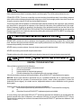
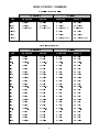
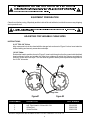
R INSTALLATION AND OPERATING INSTRUCTIONS LOWERATOR PLATE DISPENSERS Drop-In Adjustube II Drop-In Lowerator Trendline Mobile Adjustube II Trendline Mobile Dish Dispenser Mobile Adjustube II Mobile Lowerator INTENDED FOR OTHER THAN HOUSEHOLD USE RETAIN THIS MANUAL FOR FUTURE REFERENCE UNIT MUST BE KEPT CLEAR OF COMBUSTIBLES AT ALL TIMES IMPORTANT FOR FUTURE REFERENCE Please complete this information and retain this manual for the life of the equipment. For Warranty Service and/or Parts, this information is required. Model Number ! Serial Number Date Purchased WARNING: Improper installation, adjustment, alteration, service or maintenance can cause property damage, injury or death. Read the Installation, Operating and Maintenance Instructions thoroughly before installing or servicing this equipment. ! This equipment has been engineered to provide you with year-round dependable service when used according to the instructions in this manual and standard commercial kitchen practices. Phone: Fax: Toll Free: Website: E-mail: P/N 88636-00 11/05 +1 (307) 634-5801 +1 (307) 637-8071 +1 (800) 752-0863 www.apwwyott.com [email protected] APW WYOTT P.O. Box 1829 Cheyenne, WY 82003 1 APW Wyott takes pride in the design and quality of our products. When used as intended and with proper care and maintenance, you will experience years of reliable operation from this equipment. To ensure best results, it is important that you read and follow the instructions in this manual carefully. Installation and start-up should be performed by a qualified installer who thoroughly read, understands and follows these instruction. If you have questions concerning the installation, operation, maintenance or service of this product, write Technical Service Department APW/Wyott Foodservice Equipment Company, P.O. Box 1829, Cheyenne, WY 82003. SAFETY PRECAUTIONS Before installing and operating this equipment be sure everyone involved in its operation are fully trained and are aware of all precautions. Accidents and problems can result by a failure to follow fundamental rules and precautions. The following words and symbols, found in this manual, alert you to hazards to the operator, service personnel or the equipment. The words are defined as follows: ! DANGER: This symbol warns of imminenthazard which will result in serious injury or death. ! This symbol refers to a potential hazard or unsafe practice, which could result in serious injury or death. ! This symbol refers to a potential hazard or unsafe practice, which may result in minor or moderateinjury or product or property damage. ! This symbol refers to information that needs special attention or must be fully understood even though not dangerous. ! These models are designed, built, and sold for commercial use. If these models are positioned so the general public can use the equipment make sure that cautions, warnings, and operating instructions are clearly posted near each unit so that anyone using the equipment will use it correctly and not injure themselvesor harm the equipment. ! Check the data plate on this unit before installation. Connect the unit only to the voltage and frequencylisted on the data plate. Connect only to 1 or 3 phase as listed on the data plate. ! Improper installation, adjustment, alteration, service or maintenance can cause property damage, injury or death. Read the Installation, Operating and MaintenanceInstructions thoroughlybefore installing or servicing this equipment. ! The unit when installed, must be electrically grounded and comply with local codes, or in the absence of local codes, with the national electrical code ANSI/NFPA70- latest edition. Canadian installation must comply with CSA-STANDARD C.22.2 Number 0 M1982 General Requirements-CanadianElectricalCode Part II, 109-M1981-CommercialCookingAppliances. ! Local codes regarding installation vary greatly from one area to another. The National Fire Protection Association, Inc. states in its NFPA96 latest edition that local codes are Authority Having Jurisdiction when it comes to requirement for installation of equipment. Therefore, installation should comply with all local codes. ! ! WARNING: ! CAUTION: ! NOTICE: CAUTION: ! ! ! WARNING: WARNING: NOTICE: ! NOTICE: ! 2 ! Disconnect device from electrical power supply and place a Tag Out-Lockout on the power plug, indicatingthat you are working on the circuit. ! Install per the spacing requirements listed in the installation section of this manual. We strongly recommend having a competent professional install the equipment.A licensed electrician should make the electrical connections and connect power to the unit. Local codes should always be used when connecting these units to electrical power. In the absence of local codes, use the latest version of the National ElectricalCode. ! Maintenance & repair should be handled by a factory authorized agent. Before doing any maintenanceor repair, contactAPW Wyott. ! WARNING: WARNING: ! ! ! ! CAUTION: WARNING: SHOCK HAZARD - Do not open any panels that require the use of tools. Improper installation, adjustment, alteration, service or maintenance can cause property damage, injury or death. Read the Installation, Operating and MaintenanceInstructions thoroughlybefore installing or servicing this equipment. WARNING: ! ! CONTENTS Safety Precautions Maintenance General Troubleshooting Index of Model Numbers General Information Electrical Connections Equipment Preparation Adjusting for Variable China Sizes Parts Lists & Exploded Views Warranty 2 4 4 5 6 6 7 7 8 -9 11 IMMEDIATELY INSPECT FOR SHIPPING DAMAGE All containers should be examined for damage before and during unloading. The freight carrier has assumed responsibility for its safe transit and delivery. If equipment is received damaged, either apparent or concealed, a claim must be made with the delivering carrier. A) Apparent damage or loss must be noted on the freight bill at the time of delivery. It must then be signed by the carrier representative (Driver). If this is not done, the carrier may refuse the claim. The carrier can supply the necessary forms. B) Concealed damage or loss if not apparent until after equipment is uncrated, a request for inspection must be made to the carrier within 15 days. The carrier should arrange an inspection. Be certain to hold all contents and packaging material. Installation and start-up should be performed by a qualified installer who thoroughly read, understands and follows these instructions. 3 MAINTENANCE ! WARNING: surface. Never clean any electrical unit by immersing it in water. Turn off before cleaning ! Once a week or more often if necessary clean the unit thoroughly. Turn off the unit and allow it to cool. STAINLESS STEEL: To remove normal dirt or product residue from stainless steel, use ordinary soap and water (with or without detergent) applied with a sponge or cloth. Dry thoroughly with a clean cloth. Never use vinegar or corrosive cleaner. Do not use chorine based cleaners. To remove grease and food splatter or condensed vapors that have baked on the equipment, apply cleaners to a damp cloth or sponge and rub cleanser on the metal in the direction of the polished lines on the metal. Rubbing cleanser as gently as possible in the direction of the polished lines will not mar the finish of the stainless steel. NEVER RUB WITH A CIRCULAR MOTION. Soil and burnt deposits which do not respond to the above procedure can usually be removed by rubbing the surface with SCOTCH-BRITE scouring pads or STAINLESS scouring pads. ! CAUTION: Do not use ordinary steel wool as any particles left on the surface will rust. ! NEVER USE a wire brush, steel or abrasive scouring pads (except stainless), scraper, file or other steel tools. Surfaces which are marred collect dirt more rapidly and become more difficult to clean. Marring also increases the possibility of corrosive attack. NEVER use any corrosive cleaner. Use only cleaners approved for stainless steel. NEVER use cleaning solvents with a hydrocarbon base. Painted surfaces should be cleaned with a non-abrasive cleaner only (soap and water recommended). ! WARNING: SHOCK HAZARD - equipment. De-energize all power to equipment before cleaning the ! GENERAL TROUBLESHOOTING If the unit fails to operate check the following: 1. Is the unit connected to a live power source? 2. Check circuit breaker? 3. Is power switch on and pilot light glowing? 4. Check the data plate. Are you operating the unit on proper voltage? If the above checks out and you still have problems, call an APW WYOTT authorized service agency. NOTICE: Service work should be performed only by a qualified technician who is experienced in and knowledgeable with the operation of commercial gas, electric, steam cooking equipment. Contact the Authorized Service Agency for reliable service, dependable advise or other assistance and for genuine factory parts. Warranty will be void and the manufacturer is relieved of all liability if: (A) Service work is performed by other than an APW WYOTTAuthorized Service Agency or (B) Other than Genuine APW WYOTT replacement parts are installed. A current listing of all authorized APW WYOTT authorized parts/service distributors is included with this product manual at the time of shipment. In the absence of this list you can call the APW WYOTT 24 hour Service Hot Line which gives access to the nearest Authorized APW WYOTT parts/service distributor. Call 1-800-733-2203. 4 INDEX OF MODEL 1 NUMBERS DROP-IN ADJUSTUBE ADJUSTUBE II II DROP-IN TRENDLINE MOBILE BASE UNHEATED HEATED UNHEATED L-9A L-12A SL-9A SL-12A HL-9A HL-12A TL2-9A TL2-12A TL2-9A/12A HTL2-9A HTL2-12A HTL2-9A/12A HEATED ML2-9A ML2-12A ML2-9A/12A H ML3-9A ML3-12A ML3-9A/9A/12A HML2-9A HML2-12A ML2-9A/12A HML3-9A HML3-12A HML3-9A/9A/12A DROP-IN LOWERATOR DROP-IN LOWERATOR TRENDLINE MOBILE BASE UNHEATED HEATED UNHEATED HEATED L-5 L-6 L-6.5 L-7 L-8 L-9 L-10 L-12 L-5 L-6 L-6.5 L-7 L-8 L-9 L-10 L-5 L-6 L-6.5 L-7 L-8 L-9 L-10 TL2-5 TL2-6 TL2-6.5 TL2-7 TL2-8 TL2-9 TL2-10 TL2-12 TL3-5 TL3-6 TL3-6.5 TL3-7 TL3-8 TL3-9 TL3-10 TL4-5 TL4-6 TL4-6.5 TL4-7 TL4-8 TL4-9 TL4-10 HTL2-5 HTL2-6 HTL2-6.5 HTL2-7 HTL2-9 HTL2-9 HTL2-10 HTL2-12 HTL3-5 HTL3-6 HTL3-6.5 HTL3-7 HTL3-8 HTL3-9 HTL3-10 HTL4-5 HTL4-6 HTL4-6.5 HTL4-7 HTL4-8 HTL4-9 HTL4-10 ML2-5 ML2-6 ML2-6.5 ML2-7 ML2-8 ML2-9 ML2-10 ML2-12 ML3-5 ML3-6 ML3-6.5 ML3-7 ML3-8 ML3-9 ML3-10 ML4-5 ML4-6 ML4-6.5 ML4-7 ML4-8 ML4-9 ML4-10 HML2-5 HML2-6 HML2-6.5 HML2-7 HML2-8 HML2-9 HML2-10 HML2-12 HML3-5 HML3-6 HML3-6.5 HML3-7 HML3-8 HML3-9 HML3-10 HML4-5 HML4-6 HML4-6.5 HML4-7 HML4-8 HML4-9 HML4-10 5 GENERAL INFORMATION INSTALLATION: Wire the electrical cord into a junction box rated for 110 volts or 220 volts, depending on the electrical specifications of your unit. see the electrical plate on the shield for specifications. WARNING Do not attempt electrical hookup unless you have the proper tools and are qualified to do so. SPRING ADJUSTMENT: Adjustubes are factory set to an average rate. however, you may need to adjust the springs to obtain the best dispensing rate for your dinnerware. To Adjust for Rate of Rise 1. Lift the tube out of the shield. 2. Place approximately 4 inches of dinnerware into the tube, and note the height of the dinnerware above the tube. 3. Load the tube until it is approximately 3/4 full, and again note the height of the dinnerware above the tube. if the height is the same as in step 1, the rate is correct. If the height is higher than in step 1, unhook one spring from he bottom of the spring hanger, and repeat steps 2 and 3. Continue disconnecting springs from the bottom hanger until you find the proper spring combination for your dinnerware. NOTE: It is not necessary to replace the tube in the shield to place the dinnerware on the tube. leave the shield off until you find the proper adjustment. NOTE: Balance color and number of springs on all sides of the tube to provide smoothest operation. NOTE: On unheated tubes, yellow springs are stronger than silver ones (yellow are rated at 4 ounces and silver are rated at 2-1/2 ounces). On heated tubes, black springs, rated at 4 ounces, are stronger than the 2-1/2 ounce gray springs. If the height is lower than in step 1, unhook one spring from the storage bars behind the uprights and hook it onto the moveable head. Again try to balance colors and number of springs on all sides of the tube. Repeat steps 2 and 3 until a consistent dispensing rate is obtained, adding more springs as necessary. NOTE: The wire head must be centered about the spring hanger or the mechanism will bind and not move smoothly to dispense the plates. TO ADJUST FOR DISPENSING HEIGHT: Raise or lower the height of the top dish above the tube by connecting or disconnecting springs or replacing a lighter spring with a stronger one or vice-versa. TEMPERATURE ADJUSTMENT (HEATED ONLY): Remove the tube from the shield and adjust the thumbwheel located about 3 inches below the indicator light. Turn wheel up to raise the temperature and down to decrease it. ELECTRICAL CONNECTIONS ! Check the data plate on this unit to determine what voltage this unit is wired for and what voltage service to use. WARNING: 6 ! ! WARNING: IMPROPER GROUNDING COULD RESULT IN ELECTRICAL SHOCK! This appliance is equipped with a three prong (grounded) plug for your protection against electrical shock hazard and should be plugged directly into a properly grounded three prong receptacle. Do not cut or remove the groundingprong from this plug. ! EQUIPMENT PREPARATION Clean the unit before using. Wipe body and the inside of the unit with a hot, wet cloth to remove any shipping dust or protective oil. ! This unit is not intended to hold potentially hazardous foods such as un-cooked or unpreservedmeats and sausages. WARNING: ! ADJUSTING FOR VARIABLE CHINA SIZES INSTRUCTIONS: 6-1/2” TO 9-3/4” China: Align outermost hole in tube head with the storage hole as shown in Figure 1 below. Insert rods into desired setting and securely screw down rod stops. 10-3/4” China: Rotate tube head to position shown in Figure 2. Insert rods through unit so they pass inside the black head weldment below and outside the offset ring weldment to which the springs are attached. Securely screw down rod stops. This will allow for greater stability and improved rod alignment at the 10-3/4” china size. 1 3 2 Tube Head Storage Holes Figure #1 ITEM NUMBER 1 1 2 3 Figure #2 DESCRIPTION PART NUMBER Adj.Tube Head L-9A and HL-9A Adj. Tube Head L-12A and HL-12A Guide Rod Guide Rod Nut All other components are the same as the L-9 or HL-9 and the L-12 or HL-12 7 201159-00 201160-00 209315-00 209313-00 PARTS LIST & EXPLODED VIEW MODEL NUMBER TUBE DIAMETER L-5 SL-5 L-6 SL-6 L-6.5 SL-6.5 L-7 SL-7 L-8 SL-8 L-9 SL-9 L-10 SL-10 L-12 SL-12 5-1/4 6.0 6-3/4 7-1/2 8-3/8 9-3/8 10-3/8 12-1/8 S/S HEAD 201158-20 201158-21 201158-22 201158-23 201158-24 201158-25 201158-26 201158-27 HEAD WELD 205346-00 205420-00 205421-00 205422-00 205423-00 205424-00 205425-00 205347-00 OFFSET RING WELD. 204045-00 204046-00 204047-00 204048-00 204049-00 204050-00 204051-00 201165-00 4 OZ. SPRING 89023-00 89023-00 89023-00 89023-00 89023-00 89023-00 89023-00 89023-00 2-1/2 OZ. SPRING 89022-00 89022-00 89022-00 89022-00 89022-00 89022-00 89022-00 89022-00 GUIDE POST 23330-00 23330-00 23330-00 23330-00 23330-00 23330-00 23330-00 23330-00 BBC TRAY (Not Shown) 30152-00 Head Weldment S/S Head Guide Post Spring, 4 oz. or 2 ½ oz. Offset Ring Weldment 8 9 S/S Head (NOT SHOWN) Heating Element Offset Ring Weldment Thermostat Electrical Channel Insert Guide Post Spring 4 oz. Or 2 ½ oz. Push Switch & Boot Heating Element Head Weldment Pilot Light PARTS LIST & EXPLODED VIEW (UNSHIELDED - SHIELDED - UNHEATED) Notes: 10 APW WYOTT EQUIPMENT LIMITED WARRANTY APW Wyott Foodservice Equipment Company warrants it's equipment against defects in materials and workmanship, subject to the following conditions: This warranty applies to the original owner only and is not assignable. Should any product fail to function in its intended manner under normal use within the limits defined in this warranty, at the option of APW Wyott such product will be repaired or replaced by APW Wyott or its Authorized Service Agency. APW Wyott will only be responsible for charges incurred or service performed by its Authorized Service Agencies. The use of other than APW Wyott Authorized Service Agencies will void this warranty and APW Wyott will not be responsible for such work or any charges associated with same. The closest APW Wyott Authorized Service Agent must be used. This warranty covers products shipped into the 48 contiguous United States, Hawaii, metropolitan areas of Alaska and Canada. There will be no labor coverage for equipment located on any island not connected by roadway to the mainland. Warranty coverage on products used outside the 48 contiguous United States, Hawaii, and metropolitan areas of Alaska and Canada may vary. Contact the international APW Wyott distributor, dealer, or service agency for details. Time Period One year for parts and one year for labor, effective from the date of purchase by the original owner. The Authorized Service Agency may, at their option, require proof of purchase. Parts replaced under this warranty are warranted for the un-expired portion of the original product warranty only. Exceptions *Gas/Electric Cookline: Models GCB, GCRB, GF, GGM, GGT, CHP-H, EF, EG, EHP. Three (3) Year Warranty on all component parts, except switches and thermostats. (2 additional years on parts only. No labor on second or third year.) *Broiler Briquettes, Rock Grates, Cooking Grates, Burner Shields, Fireboxes: *Heat Strips: *Glass Windows, Doors, Seals, Rubber Seals, Light Bulbs: Models FD, FDL, FDD, FDDL. 90 Day Material Only. No Labor. Two (2) Year Warranty on element only. 90 Day Material Only. No labor second year. No Labor. In all cases, parts covered by extended warranty will be shipped FOB the factory after the first year. Portable Carry In Products Equipment weighing over 70 pounds or permanently installed will be serviced on-site as per the terms of this warranty. Equipment weighing 70 pounds or under, and which is not permanently installed, i.e. with cord and plug, is considered portable and is subject to the following warranty handling limitations. If portable equipment fails to operate in its intended manner on the first day of connection, or use, at APW Wyott's option or its Authorized Service Agency, it will be serviced on site or replaced. From day two through the conclusion of this warranty period, portable units must be taken to or sent prepaid to the APW Wyott Authorized Service Agency for in-warranty repairs. No mileage or travel charges are allowed on portable units after the first day of use. If the customer wants on-site service, they may receive same by paying the travel and mileage charges. Exceptions to this rule: (1) countertop warmers and cookers, which are covered under the Enhanced Warranty Program, and (2) toasters or rollergrills which have in store service. Exclusions The following conditions are not covered by warranty: *Equipment failure relating to improper installation, improper utility connection or supply and problems due to ventilation. *Equipment that has not been properly maintained, calibration of controls, adjustments, damage from improper cleaning and water damage to controls. *Equipment that has not been used in an appropriate manner, or has been subject to misuse or misapplication, neglect, abuse, accident, alteration, negligence, damage during transit, delivery or installation, fire, flood, riot or act of god. *Equipment that has the model number or serial number removed or altered. If the equipment has been changed, altered, modified or repaired by other than an Authorized Service Agency during or after the warranty period, then the manufacturer shall not be liable for any damages to any person or to any property, which may result from the use of the equipment thereafter. This warranty does not cover services performed at overtime or premium labor rates. Should service be required at times which normally involve overtime or premium labor rates, the owner shall be charged for the difference between normal service rates and such premium rates. APW Wyott does not assume any liability for extended delays in replacing or repairing any items beyond its control. In all cases, the use of other than APW Wyott Authorized OEM Replacement Parts will void this warranty. This equipment is intended for commercial use only. Warranty is void if equipment is installed in other than commercial application. Water Quality Requirements Water supply intended for a unit that has in excess of 3.0 grains of hardness per gallon (GPG) must be treated or softened before being used. Water containing over 3.0 GPG will decrease the efficiency and reduce the operation life of the unit. Note: Product failure caused by liming or sediment buildup is not covered under warranty. THE FOREGOING WARRANTY IS IN LIEU OF ANY AND ALL OTHER WARRANTIES EXPRESSED OR IMPLIED INCLUDING ANY IMPLIED WARRANTY OF MERCHANTABILITY OR FITNESS FOR PARTICULAR PURPOSES AND CONSTITUTES THE ENTIRE LIABILITY OF APW WYOTT. IN NO EVENT DOES THE LIMITED WARRANTY EXTEND BEYOND THE TERMS STATED HEREIN. 9/05 11 R Phone: Fax: Toll Free: Website: E-mail: +1 (307) 634-5801 +1 (307) 637-8071 +1 (800) 752-0863 www.apwwyott.com [email protected] APW WYOTT P.O. Box 1829 Cheyenne, WY 82003 12