1
OWNER'S
MANUAL
MODELNO,
247.384260
®
Caution:
Readand Follow
All Safety Rules
and Instructions
BeforeOperating
This Equipment
4 HORSEPOWER
4 CYCLE ENGINE
20" ROTARY
iViULCHING MOWER
Assembly
Operation
Maintenance
Service and Adjustment
Repair Parts
I,I,II,H i
i,/,_i illlll
....
SEARS,ROEBUCKANDCO., Chicago,IL 60684 U.S.A.
IMPOFITA
.. ES
FORSAFEOPERATION
,A _. ANDIORPROPERTY
OFYOURSELF
ANDOTHERS.
READANDFOLLOW
ALL INSTRUCTIONS
1NTHISMANUALBEFO
,_mL
_IJL.TO
OPERATE
YOURLAWNMOWERFAILURE
TOCOMPLYWITHTHESEINSTRUCTIONS
MAYRESULTIN PERSONAL
INJURYWHENJBIm_
_YOU
SEETHISSYMBOL-- _
DANGER:
HEEDITS WARNING.
Your lawn mower was built to be operated accordingto the rules for safe operationin this manual. As
with any type of power equipment, carelessness or error on Ihe pad of the operatorcan result in serious
injury. If you violate any of these rules, you may cause serious Injury to yourself or others°
TRAINING
Foryoursafety,usetheslopegaugeincluded
aspartofthismanual
to measureslopesbeloreoperatingthis unit on a slopedor hilly
1. Readthisowner'sguidecarefullyin itsentirety
beforeattempting
area iftheslopeisgreaterthan15`=asshownontheslopegauge,
toassembleor operatethismachineBecompletely
familiarwith
donotoperatethis uniton thatareaor seriousinjurycouldresult.
thecontrols
andtheproperuseof thismachinebeforeoperating
it. Keepthismanualin a safeplaceforfutureandregularreference
andfor ordering
replacement
parts
2 Yourrotarymowerisa precision
pieceofpowerequipment,not
PERATION
a plaything,Therefore,exerciseextremecautionatalltimesYour
Do not changetheenginegovernorsettingsor overspendthe
unit has beendesignedto performone job:to mow grass Do
engine.Excessiveenginespeedsare dangerous
not useit for any otherpurpose
2 Donotputhandsor feet nearor underrotatingparts.Keepclear
3. Neverallowchildren
under14yearsoIdto operate
a powermower
of the dischargeopeningat aHtimesas the rotatingbladecan
Children14 yearsold andovershouldonlyoperatemowerunder
causeinjury
closeparentalsuper'¢ision
Onlypersonswellacquainted
withthese
3. Stopthe bladewhen crossingg_aveldrives,walksor roads
rulesof safe operationshouldbe allowedto useyour mower.
4 After strikinga foreignobject,stop theengine,removethewire
4 Keeptheareaof operationclearof all persons,particularlysmall
from thesparkplug, andthoroughly
inspectthe mowerfor any
childrenand pets. Stopenginewhenthey are in the vicinityof
damageRepairthe damagebeforerestartingand operatingthe
your mowerto help preventblade contactor thrown objectinmower,
jury Althoughtheareaofoperationshouldbecompletelycleared
5 if theequipmentshouldstarttovibrateabnormalJy,
stoptheengine
offoreignobjects,anobjectmayhavebeenoverlookedandcouId
andcheckimmediately
forthecause.Vibrationis generally
a warnbe accidentIythrown by the mowerin anydirectionandcause
ingof trouble.
seriouspersonalinjuryto the operatoror anyothersaJtowed
in
6 Shuttheengineoff andwait untilthebladecomesto a complete
the area
stopbeforeremovingthegrasscatcheror uncloggingthechute.
PREPARATION
Thecuttingbladecontinuesto rotatefor a few secondsafter the
1. Thoroughlyinspectthe areawherethe equipmentisto be used..
engineis shut off. Neverplaceanypart of the bodyin theblade
Removealt stones,sticks wire, bonesandotherforeignobjects
areauntil you are surethe bladehasstoppedrotating,
whichcouldbe pickedupandthrownby themowertn anydirec7 Beforecleaning,
repairingor inspecting,
makecertaintheblade
tionandcausesedouspersonalinjurytotheoperatoror anyothers
andall movingpartshavestopped.Disconnect
thesparkptugwire,
allowedin thearea.Planyourmowingpatternto avoiddischarge
andkeepthewireawayfromthesparkplug to preventaccidental
of materialtoward roads,sidewalks,bystandersand the like,
starting.
2 Alwayswearsafetyglassesor eyeshieldsduringoperationor while
8 Do not run the engineindoors
performingan adjustmentor repair,to protecteyesfrom foreign
9 Nevercutgrassby pullingmowertowardyou Mowacrossthe
faceof slopes,neverup-and-down.
Exercise
extremecaution
when
objectsthat may be thrown from the machinein anydirection.
3. Wearsturdy,rough-soled
workshoesandclose-fitting
slacksand
changingdirectionon slopes.Donotmowexcesalvely
steepslopes
shirts Shirtsand pantsthat coverthe armsand legsand steelAlwaysbesureof yourfooting.A slip andtalecancauseserious
toedshoesarerecommended=
Donot wearloosefittingclothes
personal
injury.
or jewelry Theycanbe caughtin movingparts Neveroperate
10 Neveroperatemowerwithoutproperguards,platesorothersafety
a unit in barefeet, sandals,or sneakers
protective
devicesin pFace
4 Beforeworkingwithgasoline,extinguishallcigarettes,cigars,pipes
11 Mufflerand enginebecomehot and can causea burn Do not
andothersourcesof ignition Checkthefuellevelbeforestarting
touch,
the engine Gasoline
is an extremely
flammablefuel Do not fill
the gasolinetank indoors,while the engineis running,or until
enginehas beenallowedto cool for at leasttwo minutesafter
MAINTENANCE
ANDSTORAGE
running.Replacegasolinecapsecurelyand wipeoff anyspilled
1 Checkthe bladeandenginemountingbolts at frequentintervals
gasolinebeforestartingthe engineas it may causea fire or
for propertightness AJsovisuallyinspect
bladefor damage(e.g
explosion
bent, cracked).Replacewith bladewhich meetsoriginalequip5 Disengagetheself_propelled
mechanismor driveclutchon units
mentspecifications
so equippedbeforestartingthe engine
2 Keepall nuts, bolts,and screwstightto be surethe equipment
6. Thebladecontrol
handleis asafetydeviceNeverattemptto bypass
is in safeworkingcondition.
itsoperation.Doingso makesthesafetydeviceinoperative
and
3 Neverstorethemowerwithgasoline
in thetankor gascontainers
may resultinpersonalinjury throughcontactwith the rotating
inside
of a buildingwherefumesmayreachanopenflameor spark
blade.Thebladecontrolhandlemustoperateeasilyin bothdirec(e.g, gashotwaterheater).AHowtheengineto coolbeforestortions and automaticallyreturnto the disengaged
postitionwhen
released.
ingin any enclosure,
4. To reduce
fire hazard,keepthe enginefreeof grass,leavesand
7. Neverattemptto makea wheelor cuttingheightadjustment
while
excessive
oil.
the engineis running.
....................
81Ne_eTbpe-t_tethbmowetinwetgrass:Alwaysbe sureofyour ............................................
5; Checkthegrasscatcherbagfrequentlyforwearor deterioration:
................
looting. A slip and fai! cancauseseriouspersonal
injury. Keep
Replacea wornor damagedbagimmediately.Forsafetyproteca firmholdonthehandleandwork,neverrun Mowonlyin daylight
lion, replaceonly with new bag meetingoriginal equipment
or in good artificiallight
specifications_
2
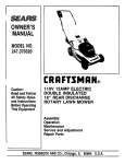
CONGRATULATIONS
on your purchase of a Sears
Craftsman Lawn Mower. l't has been designed, engineered
and manufactured to give you 'thebest possible dependability
and performance.
PRODUCT SPECIFICATIONS
iiiiii]i I
Should you experience any problem you cannot easily
remedy,
please contact
your neP,rest Sears Service
Center/Department
We have competent, well-trained technicians and the proper tools to service or repair thts unit
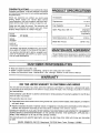
Horsepower:
Please read and retain this manual The instructi_ns wili
enable you to assemble and maintain your lawn mower
properly. Always observe the "SAFETY RULES"
Fuel Capacity'.:
MODEL
NUMBER
iiiii
]iiii]
]
LI
_
J,
4.0
Displacement:
171,9 cc
48 oz.
Spark Plug (Gap 025 in ):
Champion
RJ-19LM (or
Equivalent)
247,384260
Solid State Ignition Air Gal:.:
SERIAL
NUMBER
Blade Bolt Torque:
_0125 in,
35-40 ft lbs.
DATE OF
PURCHASE
THE MODEL AND SERIAL NUMBERS WILL BE FOUND
ON A LABEL ATTACHED TO THE REAR OF THE DECK
MAINTENANCE AGREEMENT
YOU SHOULD RECORD BOTH SERIAL NUMBER AND
DATE OF PURCHASE AND KEEP IN A SAFE PLAC:E
FOR FUTURE REFERENCE
/_ Sears Maintenance Agreement is availabfe on this
product Contact your neare_c.tSears store for details
IIIIILIIIIII
iii
iiiiiiiiiiiiiii
.................................
CUSTOMER
:
IIIII
III
III
I
I
II
...........................
i
RESPONSBBIL, JTJES
IIIII
I
I
iiiiiiiii
iiii
i
ii
i
I
•
e Read and observe the safety rules
® Follow a regular schedule in r_aintaining, caring for and using your lawn mower
o Follow the instructions under '"Maintenance" and "Storage" sections of this Owner's
:
iiiii
iiiWl
L'J_l"ll'l"l'l_l'llJLIIl_'
II
I:::
: :::
IIIII1'1
II I
I
:
::::::
::
:
iiI
Manual..
I I I
WARRANTY
OHE YEAR LIMITED WARRANTY ON CRAFTSMAHLAWN MOWER
For one year from the date of purchase, when thi_ Craftsman Lawn Mower ts maintaineo, lubricated and tunedup according to the instructions in the owner's manual, Sears wilt repair, free of charge, any defect in materiat
and workmanship.
If this Craftsman Lawn Mower is used for commercial or rental purposes, this warranty applies for only 90 days
from the date of purchase.
This warranty does not cover:
• Expendable items which become worn during normal use, such as mower blades, blade adapters, air clea_ers
and spark plugs.
• Repairs necessary because ef operator abuse or negligence, including bent crankshafts and the faille
maintain the equipment according to the instructions contained in the owner's manual..
to
WARRANTY SERVICE IS AVAILABLE BY RETURNING THE CRAFTSMAN LAWN MOWER TO THE NEAREST
SEARS SERVICE CENTER/DEPARTMENT
IN THE UNTIED STATES. THIS WARRANTY APPLIES ONLY
WHILE THIS PRODUCT IS IN USE IN THE UNITED STATES
This warranty gives you specific legal rights, and you may also have other rights which may vary from state
to state..
SEARS, ROEBUCK AND CO. Department
731CR-W Sears Tower, Chicago,
3
IL 60684
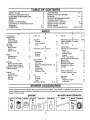
TABLE OF CONTENTS
SAFETY RULES .............................................
PRODUCT SPECIFICATIONS .....................
CUSTOMER RESPONSIBILITIES
...............
WARRANTY
.....................................
INDEX ................................................
MOWER ACCESSORIES .........................
CONTENTS OF HARDWARE PACK .............
ASSEMBLY .....................................
OPERATION .....................................
2
3
3
3
4
4
5
6, 7
8-10
MAINTENANCE .................................
SERVICE AND ADJUSTMENT
......................
STORAGE ..................................
SERVICE RECOMMENDATIONS
..................
TROUBLE SHOOTING ............................
REPAIR PARTS--MOWER
........................
REPAIR PARTS--ENGINE
..................
SLOPE GAUGE .....................................
PARTS ORDERINGtSERVlCE
.......
BACK
10, 11
12
12, t3
13
14
15, 16
17-20
21
PAGE
iNDEX
'111'"'1'1111111
'l"lll'll'l"lllll'"lllllllllllllllllllnllll
A
........................
Accessories
Adjustments:
Carburetor .......................
Cutting Height .............
Engine Speed ................
Air Filter ....................
Assembly:
Brake Cable ...............
Handle .........................
Starter' Rope .................
B
Blade:
Replacement ..................
Sharpening ...............
C
Controls:
Blade Control Handle .........
Engine Speed Control ..........
Customer Responsibilities
......
Cutting Heights ...................
E
Engine:
Lubrication ................
Speed Control ................
Starting .......................
Storage ...................
iiiiinl
nnll
nllllllll
I
F
Filter, Air ........................
4
12
9
12
11
7
6
7
10
1!
8
8
3
9
1t
8
9
12
P
Primer .........................
11
G
Gasoline:
Storage ........................
12
Tank Capacity ...............
3
Type ........................
8
H
Hardware Pack Contents ......... 5
L
Lubrication:
Engine
..................
Wheels ........................
M
Maintenance:
Agreement ..................
Air Filter .......................
Blade Care/Replacement
Engine ...................
Lubrication ................
Spark Plug ..................
Mulching Tips ..............
O
Oil:
Change .......................
Storage ....................
Type ...........................
Operating Mower ........
9, 10
R
RepairlReplacement
Parts
18-20
Responsibilities, Customer. ......
3
Rope Guide .......................
7
S
Safety Rules .......................
2
Service and Adjustments:
Blade ........................
10, 11
Carburetor ....................
12
Cutting Height ................
9
Engine
...................
12
Rear Trail ShieJd ...............
12
Service Recommendations ........ t 3
Spark Plug ..........................
t1
Specifications ......................
3
Starting the Engine ...................
9
Stopping the Mower. ..............
10
Storage ..........................
12
T
Table of Contents ...................
4
Trouble Shooting Chart
.......
14
W
Warranty ...................
3
Wheels:
Adjusting Height ..............
9
Lubrication ..........................
13
11
13
3
1I
..10, 11
1I
13
11
10
11
12
9
8, 9, !0
MOWER ACCESSORIES
These accessories were available when the mower was purchased. They are also available at most Sears retail
outlets, catalog and service center& Most Sears stores can order repair parts for you, when you provide the mode1
number of your mower.
ENGINE
Spark
Plug
¢x:=o
_==af
Air Filter
Muffler
Engine
OU
MOWER
Gas Can
Stabilizer
Blade
MAINTENANCE
Blade
Adapter
Wheels
CONTENTS OF HARDWARE PACK
(Hardware
A_
pack may contatn
extra items
which are not used on your unit. Part numbers
parentheses.)
ATTACHING
ATTACHING THE
LOWER HANDLE
Hairpinclips (714-0104)
cZ
ATTACHING
"_'t
in
THE UPPER HANDLE
Saddle
Washers
(736-0451)
l
THE STARIER
are shown
ROPE
\
C
Head
Bolts
(71 {)-1174)
l:le
Guide
(710-1205)
____._
Hex Lock Nut
t_-20 Thread
(712-0324)
ATTACHING
THE THROTTLE
CONTROL
Spring Washer
¼" LD.
(736-0175)
t_
k_=J_--
(17174) U"
EZ
SECURING THE CABLES
-._
0
INCHES
Hex Bolt
1/4-20 x 1" Long
710-0597)
Cable Ties
(726-0240)
I
2
3
Hex Nut
1/4"20 Thread
(712-0287)
i.....
ii,
r,..,.,,,,
ASSEMBLY
--
................
f
I
I
'111
_
,1_..11
IMPORTANT:
This unit is shipped WITHOUT
GASOLINE or OIL. After assembly, be certain to service engine with gasoline and oil before operating
your mower.
NOTE: Reference to right or left hand side of the
mower is observed from the operating position.
Tools Required for Assembly
(1) Pair of Pliers
(2) 7/16" Wrenches or Adjustable
(1) Flat Bladed Screwdriver
Wrenches
I Ill'
I''
iJ_l
H
INSTRUCTIONS
'1
J
jlj
UNPACKING
• Remove the lawn mower from the carton by opening the top flaps and lifting the unit out. Be careful
of the staples. Make certain all parts and literature
have been removed from the carton before the carton is discarded
• Disconnect the spark plug wire from the spark plug
and ground against the engine,
e Stretch out control cable and place on the floor,. Be
careful not to bend or kink the cable at any time during assembly
@ Lay out the contents of the hardware pack according to the illustration on page 5 for identification
k_\\
\
Lower
Handle
\
Mounting
\\ \
Bracket
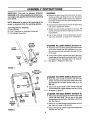
ATTACHING THE LOWER HANDLE (Hardware A)
® Attach the lower' handle by placing the bottom holes
in the lower handle over the weld pins on the handle mounting brackets extending through the rear
of the deck.
).\.
e Using a pair' of pliers, squeeze one leg of the lower'
handle against the handle mounting bracket, Insert
the hairpin clip into the inner hole in the weld pin_
-.-------See figure 1_ Repeat on other side.
FIGURE 1.
Hole In
Blade Control
lie
Cable
Bracket
Bolt
Spring
Washer
Hand
Curved
Washer
Carriage
..........................
Bolt .................
FIGURE 2.
Hex
Nut
ATTACHINGTHE UPPERHANDLE(HardwareB)
• Place the upper handle in position over the lower
handle. The hole in the side of the blade control handle (attached to the upper handle) must be on the
left side.
® Secure the upper handle to lower handle using the
curved head bolts, saddle washers and hand knobs
-._------as shown in figure 2.
ATTACHINGTHE CABLEBRACKET(Hardware D)
• Place cable bracket against the inside of the upper
handle (left hand side), The top part of the cable
bracket should be just below the blade control handle See figure 2o
e Place 114" hex bolt through cable bracket and handte_ from the inside to the outside_ ....................................................
e Secure with spring washer (cupped side against the
handle) and hex nut,,
"Z"
ATTACHINGTtlE BRAKECABLE
Fitting
\
Control
Handte
® The brake cable is attached to the engine, and has
a "Z" fitting on the loose end, Route the brake cable
below the bower handler Place end of cable through
.-.------the
hole in the bracket as shown in figure 3, Be
careful not to bend or kink the cable at any time
Push the plastic fitting until it locks into the hole in
the bracket
Hole in
sembled
proper
bladebebrake
WARNING:as shown
Brake for
cable
must
asoperation.
Plastic Fitting
e Hook the "Z" end of the brake cable into the hole
in the blade control handle from the inside to the outside as shown in figure 3,,
FIGURE 3_
SECURING THE CABLE (Hardware E)
Secure cable to the left side of the handle as foliows,
\
\
_
cable, the cable must be routed to avoid
WARNING: When attaching the control
contact with all sharp edges and hot surfaces to prevent damage to the cable,
which will render the control inoperative.
e Insert posts on cable ties into holes provided on the
handles, one on the upper handle and two on the
lower handle,, The holes may be either on the inside
•.,------or outside of the handle_;, See figure 4A
on_
Cable Tie
• Secure the cable with, the cable ties See figure 4B.
FIGURE ,I.
e Trim excess ends of cabie ties
Starter
Handle
ATTACHING THE STARTER ROPE (Hardware C)
Lock
Nut
• The starter rope is inside the top of the engine. Additional rope may be wound around the starter handle- If so, unwind the rope from [_hehandier
® With the spark plug wire disconnected
and
grounded, depress the blade control handle and pull
the rope out of the engine
Rope Guide
• Place the rope guide around the starter handle, so
the rope guide bends downward as shown in figure
-.,_'--_5 Insert the rope guide into the handle, and secure
with hex lock nut.
FINAL ASSEMBLY OF MOWER
• Make certain
securely,
FIGURE 5.
7
al! nuts and bohs are tightened
illlllllllllllll
OPERATION
.......................................
,,,,,,,,,,,
,,,,,,,,,
,,,,,,
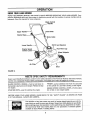
KNOWYOURLAWNMOWER
READ THIS OWNER'S MANUAL AND SAFETY RULES BEFORE OPERATING YOUR LAWN MOWER_ Compare the illustrations with your lawn mower to familiarize yourself with the location of various controls and adjustmentso Save this manual for future reference,
Blade Control
Hand Knob
Upper Ha
Starter Ro
rake Cable
Lower
Oil Fill and Dipstick
Filler Cap
Engine Speed
Control
Wheel Adjuster
Primer
Air
D_eck
FIGURE 6.
"'
IVIEETS""cPSC
SAFETY: REQUIREMENTS
'
Sears Lawn Walk-Behind Mowers conform to the safety standards of the American Nationa! Standards Institute,
and the U.S. Consumer Product Safety Commission. The blade turns when the engine is running,
BLADE CONTROL HANDLE--must
be held down to
the handle to start and run the engine, Release to stop
the engine.
STARTER ROPEwused
for starting the engine
PRiMER--pumps
additional fuel from the carburetor
to the cylinder' for use when starting a cold engine°
ENGINE SPEED CONTROL LEVER--Permits
tion of fast or stow engine speed.
BEFORE U StNG YOUR LAWN MOWER, AGAIN REFER "TO THE "SAFETY
2 OF THIS 'MANUAL. ALWAYS BE CAREFUL.
RULES"
selec-
AS SHOWN ON PAGE
The operation of any lawn mower can result in foreign objects being thrown into the
eyes, which can result in severe eye damage._ Always wear safety glasses or eye shields
..........................
before.starting power tool operation orwhile performing any,adjustments or,repairs ..............................
We recommend Wide Vision Safety Mask for over spectacles or standard glasses
available at Sears Retail or Catalog Stores.
HOWTO USEYOURMOWER
NOT use I=.lhyLor high octane g;_s0tine,Be certain
BLADE CONTROL HANDLE
container is clean and frc.=efrom rust or foreign par..
ticles Never use gasoline that "nay be stale from
long periods of storage in the container.
Your mower has a control handle which reqtJires the
operator to be behind the handle to start and run the
mower. When the operator releases the contro_ hanate the engine will stop and an interna_bra_,e helps _he
blade to stop quickly.
When the operator
change the cutting
jects in the way, the
the control handle
leave_ the (:.perating position to
heighl, pick t,p sticks c_ro_her obengine will stop automa:icaqy wheq
is released.
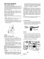
ADJUST CtJTTING HEIGHT
• Raise wheels for low cut and I.:_werwheels {or high
cUL
CAUTION: E q_erience indicates th _t alcohol blended
fuels (calted §asohol or ,jsing ethanul or methanol1 can
attract moisture which leads _o sep,_ration and formation of acids during storage. Acidic gas can damage
the fuel system of an engine white ir storage To avoid
engine problems, the fuel system ._hould be emptied
before storage tor 30 days. or longer Jse fresh fuel next
season See .'-_TORAGESECTION f3r additional infcr-l_atior_.
Never use engine or caro:Jrelor cleanser products in the
!uel tank o_ _ermanent damage m_y occur.
• Adjust cutting height to suit you, reeuimrr, ents
Medium position is best for most lawns
® To change cutting height, squeeze adjuster lever
toward wheel See figure 7 Move wheel up rjr down
to suit/out requirements Be sure z{llwbeefs are in
the same setting,
TO START ENGtNE
e Connect s!)a_k plug _,ire to spar'_ plug. Make certain the meta; loop or lhe end of t'le spark plug wire
(inside the "ubber boot) is fastened securely over the
meta_ tip _n :he spa.'.',.:ptug Se_ figure 8
Metal Loop
on Spark
Plug Wire
Boot
=IGURE 8.
e Press prirrer
FIGURE 7,
BEFORE STARTING
ENGINE
• Place unit so engine is in a level position
e Fill crankcase with oil using a h gh quality detergent'
oil classified "For service SC, ,SD, SE or SF " such
as SAE 30 (SAE 10W-30 is a_: acceptable substi
tute) DO NOT USE !OW40 OIL
Remove oil fit! cap
slowly until oil level
Crankcase capacity
ounces) DO NOT
button as follows (;old starts only)
For each in,tia! start, push primer button five (5)
times prior to starter operation -3ee figure 9 Use
sharp pus_'es, wait between each push Repeat the
above for each starter operation as necessary Do
not use primer for warm engine restarts
e Set engine s!:_eed control 1o HI _;peed
Engine Speed
mtrol Lever
and oipstick assembly. Pour oi!
is to the FULL mark on d,pstick
is approximately lq !4 p=nts (20
OVERFILL
NOTE: Crankcase oil should be changed after lirst two
(2) hours of operation and every twenty-five (25) hours
thereafter Refer to ENGINE LUBRICATION section on
page 11,
• Replace
securely
oil fill cap and dipstick
Tighten
,sap
• Fill gas tank with about one (I) quart of clean, fresh,
lead4ree grade automotive gasoline., Low-lead or
regular gasoline is an acceptable substitute. DO
/
1
LOW
FIGURE 9,
\
\
H!
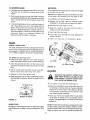
e
Hold blade control handle against upper handle.. See
figure 10. Pull starter handle quickly_ Do not allow
starter rope to snap back
TO STOP ENGINE
Release blade control handle to stop engine_ Disconnect the spark plug wire and move it away from the
spark plug to prevent accidental starting while equipment is unattended
o If desired, move engine speed control to LOW for
light mowing conditions°
MULCHING TIPS
e Under certain conditions, such as very tall grass, it
may be necessary to raise the height of cut to reduce
pushing effort and to keep from overloading the
engine and leaving clumps of grass clippings,
Starter
Handle
Handillll
1
® For extremely heavy cutting, reduce the width of cut
e Under heavy conditions cross cut for additional
mulching of surface debris,
FIGURE 10.
MAINTENANCE
,, ,,, ,,,, ,,,,,,,,,,,,,,
GENERALRECOMMENDATIONS
® Once a year' you should replace the spark plug, air
filter', and check blade for wear. A new spark plug
and air filter assures proper air-fuel mixture and
helps your engine run better and last longer.
e Follow the Service Recommendation
,,,,
,,,,,,,,,,,,ll=l=l
jll
iji
:
e Assemble bolts, washers, and nuts in the exact order
of removal.
e Use block of wood to hold blade and tighten bolt
clockwise, The recommended torque is 35-40 ft= Ibs..
Torque wrenches are available at most Sears stores
and through the catalog,
Schedule on
NOTE: The bolt used to secure the blade to engine is
specially heat-treated_ Do not substitute (See Repair
Parts)..
page 13.,
MOWER
BLADE CARE
CAUTION: A LOOSE BLADE CAN BE
DANGEROUS
AND MAY MAKE THE
ENGINE HARD TO START.
Your mower will work better with a sharp blade..
CAUTION: DISCONNECT SPARK PLUG
WIRE FROM SPARK PLUG AND PLACE
WIRE WHERE IT CANNOT COME IN CONTACT WITH THE SPARK PLUG.
Use only a Sears authorized replacement
the best cutting results..
TO REMOVE BLADE (See Figure 11):
e Turn mower on its side. Make sure air filter and carburetor are upo
blade to get
Washer
® Use a block of wood between blade and mower deck
to prevent blade from turning when bolt is removed.
Protect your hands with gloves and/or wrap blade
with heavy cloth_
Small Bo
Washer
e Remove blade bolt by turning counterclockwise. Use
a 91t6" box or open.end wrench.
"Large Bolt
TO REPLACE BLADE (See Figure 11):
FIGURE 11.
...................
e Pu t •bl ade adapter o ne ngl nec ran ks haft: ....................................................................................................................................................
e Fit blade in adapter. Be sure trailing edge of blade
is up towards engine,
NOTE: We do not recommend sharpening the blade-but if you do, be sure blade is balanced.
10
TO SHARPEN BLADE:
AIR FILTER
e The blade can be sharpened with a file or on a grinding wheel Do not attempt to sharpen while on the
mower
Your engine will not run properly an :t may be damaged
by using a dirty air filter..
e Care should be taken to keep the blade balanced
An unbalanced blade will cau_._eexcessive vibration
when running and eventual damage to mower and
engine.
TO CHANGE-" AIR FILTER (See Fi;]ure 13):
Replace the air filter every year, more often if you mow
in very dusty, dirty conditions Do not wash air filter
e Remove 1he air filter cover by turning counterclockwise to the stop and Dull away from collar
® To check blade balance, drive a nail into a beam or
o Remove filter from inside of cover
wall.. Leave about one _nch cf the stra+ght nail exposed. Place center ho+e of blade over the head of
the nai!. If blade is balanced, it should remain in a
horizontal position if either er+dof the blade moves
downward, blade is not balanced. Sharper_ the
heavy end until the blade is balanced
e Clean the +nside of the cover and the collar to
remove an_ dirt accumulation
• Insert new Iilter into cover
e Put air filter cover and filler into collar aligning the
lab with the slot.
e Push in on cover and tt.rn cloct;wise to lighten
ENGINr
Collar
ENGINE LUBRICATION
You must change the oil in the crankcase after the first
two (2) hours of operation and after each 25 hours of
tJse thereafter CHANGE THE O11..MORE FREQUENTLY IF LISED tN SANDY OR DLISTY COI',IDI [+IONS
Turn
Clockwise
To Remove
Sh
TO DRAIN OIL (See Figure 12)
e Disconnect spark plug wire _rom spark plug and
place wire where it cannot come in contact with plug.
Tab
Air Flit /
® Drain the gas tank and then turn the mower on its
side with the carburetor side ui:)and remove oil drain
plug
Air Filter
FIGURE
e Set the mower down and drain oi! into a flat pan
NOTE: Oil will drain more freely when warm
13,
CLEANING
e Replace oil drain plug, tighten firmly.
WARNING: DISCONNECT SPARK PLUG
WIRE FROM SPARK PLUG AND PLACE
WIRE WHERE IT CANNOT COME IN CONTACr WiTH THE SPARK PLUG.
e Refill crankcase with oil Refer to BEFORE STARTING ENGINE in operation see:Lion on page 9 of this
manual
Oil Drain
+,Turn Clockwise
To Tighten
Cover
Plug
Bottom of Encjine
FIGURE 12.
SPARK PLUG
@
Turn mower on its side with carburetor
O
Clean the underside of your mower after each use
by scraping t+oremove build-up of grass clippings,
leaves, dirt or other matter, tf this debris is allowed
to accumulate, it will invite rust and corrosion, and
may prevent proper mulching
O
Clean your mower and engine often to keep buildup of grass or debris from accumulating around
engine. A clogged engine runs hotter and shortens
engine life.
up
NOTE'. We DO NOT recommend using a garden hose
to clean mower unless the electrical system, muffler,
air filter and carburetor are covered to keep water out
Water in engine can result in shorlening engine life..
Change your spark plug each yea_ to make your engine
start easier and run better Set spark plug gap at .025
inch.
11
lUr ir
i, .....................
:...........:.............
i ii
uu
i
i
i
illllll,l,lllliM,ul
iiilllll
ii
ill
..............
SERVICE AND ADJUSTMENTS
TO ADJUST CUTTING
HEIGHT
Refer to "ADJUST CUTTING
section of manual,
HEIGHT"
set. Do not attempt to increase engine speed or it may
result in personal injury If you believe that the engine
is running too fast or too slow, take your mower to art
authorized Sears Service Center' for repair and ad*
justment.
in operation
CARBURETOR
Your carburetor has a non-adjustable fixed main jet for
mixture control It has been completely adjusted at the
factory° tf your engine does not operate properly due
to suspected carburetor problems, take your mower to
an authorized Sears Service Center for repair and adjustment.
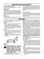
REAR TRAIL SHIELD
ENGINE SPEED
The rear trail shield, attached between the rear wheels
of your mower, is provided to minimize the possibility
that objects wilt be thrown out the rear of the mower
toward the operator,
Your engine slow and fast speeds have been factory
If the shield becomes damaged, it should be replaced
STORAGE
NOTE: GASOLINE
MUST BE REMOVED
OR
TREATED TO PREVENT GUM DEPOSITS FROM
FORMING IN THE TANK, FILTER, HOSE AND CARBURETOR DURING STORAGE
ALSO DURING
STORAGE, ALCOHOL-BLENDED
GASOLINE THAT
USES ETHANOL OR METHANOL
(SOMETIMES
CALLED GASOHOL) ATTRACTS WATER. IT ACTS
ON THE GASOLINE 'TO FORM ACIDS WHICH
DAMAGE THE ENGINE.
Your mower and engine should be prepared for offseason storage as follows:
MOWER
® Clean underside of mower housing (See "CLEANING" in maintenance section of manual).
® Inspect and replacelsharpen blade, if required (See
"BLADE CARE" in maintenance section of manual).
e Lubricate as shown in Service Recommendation
chart on page 13 of manual.
HANDLE
To remove gasoline, run engine until tank is empty and
engine stops. If you do not want to remove gasoline,
Sears Craftsman Fuel Stabilizer No_ 33500 may be
added to any gasoline left in the tank to minimize gum
deposits and acids. If the tank is almost empty, mix
stabilizer with fresh gasoline in a separate container
and add some to the tank, Always follow instructions
on stabilizer container. Then run engine at least 10
minutes after stabittzer is added to allow mixture to
reach carburetor.
e You carl fold your mowers' upper handle for storage
as shown in figure 14. Loosen the two (2) hand
knobs on sides of the handle and let the upper handle fotd down to the rear.
CAUTION: When folding handle for storage or
transportation, be careful not to bend or kink the
brake cable
You can heip keep your engine in good operating condition during storage by:
e Changing oil.
e Lubricating the piston/cylinder area by first removing the spark plug and squirting clean engine oil into the spark ptug hole. Then cover the spark plug
hole with a rag to absorb oil spray. Next, rotate the
engine by pulling the starter' two or three times.
Finally, reinstall spark plug and attach spark plug
wire.
OTHER
FIGURE 14.
ENGINE
A
WARNING: NEVER STORE YOUR LAWN
MOWER INDOORS OR IN AN ENCLOSED,
POORLY
VENTILATED
AREA
IF
GASOLINE
REMAINS
IN THE TANK.
FUMES MAY REACH AN OPEN FLAME,
SPARK OR PILOT LIGHT FROM A FURDRYER, CIGARETTE,
• Do not store gasoline from one season to another
® Replace your gasoline can if your can starts to rusL
Rust and/or dirt in your gasoline can cause
problems.
ETC.
Plastic cannot breathe which allows condensation
to form and cause the metal components of your
mower to rust
To prevent engine damage if lawn mower is not used
for more than 30 days, follow the steps below,
12
I
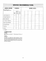
SERVICE RECORD I
SCHEDULE
SERVICE DATES
I
Fill in dates as you
complete regular service
l ................
A[Ier
First
[Every
Every
Two
25
Use
Hours
Hours
Check Engine (')il
if
Change Engine Oil
Blade Replaced
p
Air Cleaner Replaced
Spark Plug Replaced
Lubricate
p_
Mower
t
Cleaning
1
Muffler
P
"
,i CHECK
LUBRICATION
ENGINE
See "Engine
Manual_
Lubrication"
n Maintenance
Se,:tion of
WHEELS
DO NOT oil or grease the wheel bearings Viscous
lubricants will attract dust and dirt that wilt shorten the
life of the ,'}elf-lubricating wheel be_rings.. If you ._eelthe
wheels m_.tslbe lubricated, use only a dry, silicone type
lubricant ,,}paringly.
13
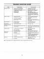
TROUBLE SHOOTING
Trouble
Engine fails to start
Engine runs erratic
Possible
1
2
3
4
5
6
7
Engine
overheats
Cause(s)
Blade control handle disengaged
Spark p+ug wire disconnected
Throttle contfot lever not in starting
Fuel tank empty, or stale fuel
Blocked fuel line
Faulty spark plug
Engine flooded
Corrective
1..
2
position
1, Spark plug w+re loose
2 B+ocked fuel line or stale fuel
3
4
5
Vent in gas cap plugged
Water or dirt in fuel system
Dirty air cleaner
1 Engine oillevel low
2. Air flow _estr+cted
Occasional skip
(hesitates) at high speed
GUIDE
3,.
4
5
6
7
Actfon
Engage blade control handie
Connect wire to spark plug.
Move throttle lever to starting position+
Fill tank with clean, fresh gasoiine
Clean fuel line
Clean, adjust gap oc replace
Remove spark plug, dry the plug. and
crank engine with plug removed and
throttle in off position Replace spark
plug, connect wire and resume starting
procedures
1.+ Connect and lighten spark plug wire
2. Clean fuel line; fill tank with clean
fresh gasoline
3 Clear vent
4 Drain fuet tank Refill with fresh fuel
5 Clean air cteaner See maintenance section
of this manual
1. Fift crankcase with proper oil
2 Clean lawn mower engine
Spark plug gap too close
Adjust gap to 030"
tdies poorly
1 Spark plug lou{ed,
2 Dirty air cleaner
Excessive
I
Cutting
2
3
Bent cutting b+ade
Bent engine crankshaft.
2
3
i
2
Engine speed too low
Wet grass
3
Excessively high grass,
1 Move throttle iever to FAST position
2 Do not mow when grass is wet; watt until
later to cut.
3 Mow once at a high cutting height, then
mow again at desired height or make a
narrower cutting swath ('U2 width)..
4 Sharpen or replace blade
vibration
Mower will not
mulch grass
fautty or gap too wide
blade loose or unbaianced
4. Dull blade
Uneven cut
t
Wheels not pos+ttoned correctly
2+ Dull blade,
Note;
For repairs beyond
the minor adjustments
l
2
Reset gap to 030" or replace spark plug
Clean air cleaner See ma+ntenance section
of this manual
i
Tighten bfade and adapter
Balance blade
Replace blade.
Contact your SEARS Service
Place all four wheels in same
height position.
2. Sharpen or replace blade.
1.
listed above, contact your nearest SEARS
14
Service Center
Center
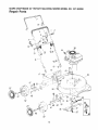
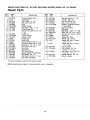
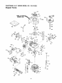
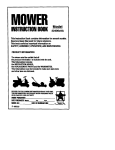
SEARS CRAFTSMAN 20" ROTARY MULCHING MOWER MODEL NO. 247.384260
Repair Parts
10
44
39
\
47
/
\
48
\
52
15
SEARS
CRAFTSMAN
20" ROTARY
MULCHING
MOWER
MODEL
NO. 247.384260
Repair Parts
PART
NO.
KEY
NO.
1
3
5
6
7
8
9
10
13
747-0748
17t 74
736-0175
7! 2-0287
720-0226
749-0756A
710-0597
7t0-1205
710-! 174
14
15
16
17
18
19
2O
21
22
23
25
29
30
3t
32
33
726-0240
749-0372B
714-0104
17098
731-0872
12935A
12936A
736-0356
712-0798
731-0981A
720-0241
682-0002
753-0485
736-0453
710_0757
742-050O
I KEY
DESCRIPTION
Control Handle Ass'y,
Cable Brkt
SpL Wash, t/4" I D,
Hex Nut 1/4-20 Thd"
Grip
Upper Handle
Hex Bolt V4-20 x t" Lg,
Rope Guide Bolt
Curved Hd Bolt 5/16-18 x 2"
Lg_
Cable Tie
Lower Handle
Hairpin Cotter
Hinge Clip
Rear Flap
Handle Bracket Ass'y,mLH,
Handle Bracket Ass'y,--R.H,
Bell-Wash, .39" ID, x 1,38"
Hex Nut 318-16 Thd.*
Hub Cap
Hand Knob
20" Deck Ass'y_
Blade Adapter Kit (Splined)
Bell-Wash. _46" toD_
Hex Bolt 7/t6-20 x 1,5" Lg.
20" Mulching Blade
*Common Hardware--May
NOTE: Specifications
Be Purchased
r NO.
PART
NO,
34
710-1055
E35 736-0169
i 36 712-0241
712-0324
143_414292
39
44
735-0639
46 738-0102
47
48
49
50
5!
52
53
736-0105
738-0507B
14832
t5262B
15261A
734-15t2A
14578
14579
55
57
746-0735
710-0654A
59
710-0603
60
736-0451
770-7192F
Locally,,
subject to change without notice or obligation
16
DESCRIPTION
Hex Bolt 3/8-24 x 1" Lg
L-Wash, 3/8" I.D.*
Hex Nut 3/8-24 Thd.
Hex [,-Nut V4,20 Thd
Engine--Craftsman
Model
143,,414292
Spark Plug Boot
Axle Bolt
Bell-Wash_ ,400" LD,, x _88"
Shld Bolt 50" Dia, x ,,357"
Spring Lever Ass'y wtKnob
Pivot Bar
Height Adj_ Plate
Wheel Ass'y, Comp,
Height Adj, Ass'y_ Comp,-R.F, & LR
Height Adj_ Ass'y_ Compo-L,F,, & R,R
Control Cable
Hex L-Wash Hd Scr
3/8-16 x 1 0" Lg.
Hex Wash, Hd. B-Tap Scr,
5/16-18 x .5" Lgo
Saddte Washer ,32" I,D,
Owner's Guide
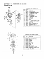
CRAFTSMAN 4 H.P, ENGINE MODEL NO. 143,414292
Repair Parts
ij_ 292
/
4O0
290
126
125
45A
30j
i
1
241
17
CRAFTSMAN
4 H.P. ENGINE
MODEL
NO. 143.414292
Repair Parts
KEY
NO.
1
PART
NO.
DESCRIPTION
KEY
NO.
35010
PART
NO.
DESCRIPTION
Cylinder Ass'y (Incl. Nos.
92
650815
Washer, Belleville
2 & 20)
93
650816
Nut, Flywheel
2
26727
Pin, Dowel
100
34443A
Solid State Ass'y,
6
33734
Element, Breather
10t
610118
Cover, Spark Plug
7
34214A
650814
Screw, Torx "1"-15Hex Washer
Breatller Ass'y. (Incl Nos 6, 8, 103
9, 12A & 12B)
Hd Sems, 10-24 x 1
8
*33735
Gasket, Breather
1t0
34961
Wire, Ground
9
30200
Screw, Hex Washer Hal.
1t9
"330t5A
Gasket, Cylinder Head
Self-Tap Seres, 10-24 x 9/16
120
34342
Head, Cylinder
12A 34695
Elbow, Breather Tube
125
29315C
Valve, Exhaust (Std) (Incl.
12B 33886
Tube, Breather
No. 151)
14
28277
Washer, Flat
125
29316C
Valve, Exhaust (1/32" oversize)
15
30589
Rod, Governor (tnct. No. 14)
(lncl, No, 151)
16
31383A
Lever, Governor
126
29314B
Valve, Intake (Std.) (IncL
17
31335
Clamp, Governor Lever
No. 151)
18
650548
Screw, Hex Washer Hd
126
29315C
Valve, Intake (1/32" oversize)
8-32 x 5/16
(Incl. No 151)
19
31361
Spring, Extension
130
6021A
Screw, Hex Flange Hd,.,
20
32600
5/16-18 x 11/2
Seal, Oil
30
35612
Crankshaft Ass'y
135
35395
Spark Plug, Resistor (Champion
40
35544
Piston, Pin & Ring Ass'y. (Std)
RJ-19LM or equivalent)
(Incl.. Nos. 41, 42 & 43)
150
31672
Spring, Valve
4O
35545
Piston, Pin & Ring Ass'y, (.010
151
31673
Cap, Lower Valve Spring
oversize) (tnct Nos. 41,
169
"27234A
Gasket, Valve Spring Box
42 & 43)
172
32755
Cover, Valve Spring Box
4O
35546
Piston, Pin & Ring Ass'y ( 020
174
650128
Screw, Hex Hd Sems,
10-24 x 1/2
oversize) (tnct. Nos 41,
42 & 43)
178
29752
Nut & Lockwasher, t/4-28
41
35541
Piston & Pin Ass'y (Std)
182
6201
Screw, Hex Hal, t/4-28 x 7t8
(incl., No. 43)
184
*26756
Gasket, Carburetor
41
35542
Piston & Pin Ass'y_ (010
185
31384A
Pipe, Intake (lnc[ No.. 224)
oversize) (Incl. No. 43)
186
34337
Link, Governor Spring
41
35543
Piston & Pin Ass'y (020
189
650839
Screw, Hex Washer Hd.
oversize) (incl No. 43)
Powerlok, 1/4-20 x 3/8
42
35547
190
35831
Lever, Brake
Ring Set, Piston (Std,)
42
35548
Ring Set, Piston (.0t0 oversize)
191
35040A
Bracket, SE Brake (Incl.
42
35549
Ring Set, Piston (.020 oversize)
No, 195)
43
20381
Ring, Piston Pin Retaining
192
34966
Link, Control
45A 32875
Rod Ass'y,, Connecting
193
35830
Spring, Extension
(Incl. No.. 46)
194
32309
Ring, Retaining
46
32610A
Bolt, Connecting Rod
195
610973
Terminal Ass'y.
27241
48
Valve, Lifter
200
33205A
Bracket Ass'y, Control (incL
50
33148A
Camshaft (Compression Release)
Nos.. 202 thru 205)
52
29914
Pump Ass'y. Oil
202
33802
Spring, Compression
69
*35261
Gasket, Mounting Flange
203
31342
Spring, Compression
70
34311C
Flange, Mounting (Incl Nos.
204
650549
Screw, FiL Hd, 5-40 x 7/16
72, 73, 75 & 80)
205
650777
Screw, Fil_ Hd, 6-32 x 21/32
72
30572
Plug, Oil Drain (Incl. No.. 73)
207
34336
Link, Throttle
*28833
73
Gasket, Oil Plug (Not required
209
30200
Screw, Hex Washer Hd Selfwith plastic oif plug)
Tap Sems,10-24 x 9f16
75
27897
Seat, Oil
215
32410
Knob, Control
8O
30574
Shaft, Governor
223
650451
Screw, Hex Hd. Seres, 1/4-20x 1
81
30590A
Washer', Flat
224
"34690A
Gasket, intake Pipe
82
30591
Gear Ass'y, Governor (Incl.
238
650932
Screw, Hex Washer Hd Shld.,
10-32 x 49t64
No. 81)
83
30588A
Spool, Governor
239
*34338
Gasket, Air Cleaner
84
29193
Ring, Retaining
241
35797
Collar, Air Cleaner
86 ..........
650488 ........................................
Screw; Hex Hd: Sems, .................................................
245 .............
35066 ......................................................
Filter; Air Cleaner (Paper) ................................
t/4-20 x 11/4
250
35065
Cover, Air Cleaner
89
611004
Key, Flywheel
260
35393
Housing, Blower
9O
611112
Flywheel
18
CRAFTSMAN
4 H.P. ENGINE MODEL NO. 143.414292
Repair Parts
-3
KEY
NO,
PART
NO.
261
30200
262
65083I
275
277
285
287
35708
650795
35000
650884
290
292
298
30705
26460
28763
300
301
34369A
35355
KE_q
NOJ,
DESCRIPTION
Screw, Hex Washer Hd SelfTap Seres, 10-24 x 9/16
Screw, He_,.Washer Hd
Powerlot_ Thd, 1/i-20 x t.,5/32
Muffler As-_/y (Incl No 277)
Screw, Her', Hd.., I/4-20 > 2_,_
Hub, Starter
Screw, He)= Washer Hd,
8-32 x t/2
Line, Fuel
Clamp, Fuel Line
Screw, He)= Washer Hd Silakeproof, 10932 x 35/64
Tank Ass'y (fncl Nos 292 & 301)
Cap, Fuel
305
306
30T
30;=
PART
NO.
35577
34265
35499
650562
3tC_ 35578
313_34080
32:" _35392
37(}A! 34346
37(}C't 35167
380 { 632569
39(} l 590621
40(} I 33238D
............
"Indicates Parts included in
Gasket Set, Ref No ,400
19
__
DESCRIPTION
~1
Tube, Oi! Fill
|
Gasket, Fill ] ube
|
"O" Ring
i
Screw, Hex Washer Hal. Shakeproof, 10-32 x V2
Dipstick Oil Fill
Spacer, Flywqeel Key
Plug, Starter
Decal, Instruction
Decal, Instruction
Carburetor (Inct No. 184)
Starter, Rewiqd
Gasket Set (Incl items
ma_ked , )
CRAFTSMAN
4 H.P. ENGINE
MODEL
NO. 143.414292
Repair Parts
PARTS LIST FOR CARBURETOR
KEY 1
NO,,1
t
5!
6 I
16!
25
27
28
29
30
I
I
I
J
]
PART
NO
DESCRIPTION
632569
6316t 5
631767
631184
631971
631616
6505O6
632527
631700
631024
632019
631028
631021
Carburetor Comp
Throttle Shaft & Lever Ass'y,
Throttle Return Spring
Dust Seal Washer
Dust Seal
Throttle Shutter
Throttte Shutter Screw
Fuel Fitting
Float Bowl
Float Shaft
Float
"O" Ring, Float Bowl to Body
inlet Needle, Seat & Clip (lncl,
No. 31)
Spring Clip
Primer Bulb/Retainer Ring
High Speed Bow! Nut
Bowl Nut Washer
Welch Plug, Atmospheric Vent
31 I 631022
35 I 632047
40 I 632071
44 1 631334
48 I 631027
PARTS
_>--4
_-,,
NOo
PART
NO_
1
2
3
4
5
6
7
8
9
10
11
12
590621
590599A
590600
590615
590601
590598
590616
590617
590618
590619
590620
590622
590535
13
590452
LIST
FOR
REWIND
STARTER
DESCRIPTION
Rewind Starter Comp
Pin, Spring (Incl, No 4)
Washer
Retainer
Washer
Spring, Brake
Dog, Starter
Spring, Dog
Puliey
Spring, Rewind
Cover, Spring
Housing Ass'y. Starter
Rope, Starter (Length 98" &
9/64" Dia)
Handle, Starter
5
.................................................................................................................................
_,_"_2 ..........................................................................................................................................................................................
2O
LO
C:
(Keep this sheet for future
m
.._
reference.)
i
i
m
I
•
!
!
I
I
I
i
I
I
I
i
I
I
I
t
I
i
I
I
I
I
:I:
-!
o)
_n
-lm
rn
-i
_n
m
0
Ill
-4
0
0
rn
-4
rn
:Z:I
Z
!3
0
rEI
-t
::1::
r'rrt
Z
m
r-
0
m
ITi
r"
o
-i
3:
:g*
:g,
:o
t
t
I11
m
rrt
:i:l
"-1
0
c::
:I:,,
r"
.,-t
m
m
Z
0
-4
e
I!l
ill
iI
it
0
"0
m
i
-4
m
o)
"/I
m
F
i
21
CRRFTSMRH®
4 HORSEPOWER
4 CYCLE ENGINE
20" ROTARY
MULCHING MOWER
Each lawn mower has its own model
engine has its own model number,
number.
Each
The model number for your lawn mower will be found on
a label attached to the rear of the deck.
The model number for the engine will be found on the
blower housing of the engine adjacent to the spark plug
All parts listed herein may be ordered through Sears,
Roebuck and Co. Service Centers and most Retail Stores.
WHEN ORDERING
THE FOLLOWING
HOWTO
PARTS
* PRODUCT-
"20"
* MODEL
NUMBER
* ENGINE
MODEL
REPAIR PARTS,
INFORMATION:
Rotary
Mulching
ALWAYS
GWE
Mower"
- 247.384260
NO. - 143.414292
* PART
NUMBER
* PART
DESCRIPTION
Your Sears merchandise has added value when you consider that Sears has service units nationwide staffed with
Sears trained technicians .... professional
technicians
specifically trained on Sears products, having the parts,
tools and the equipment to insure that we meet our pledge
to you.° _we service what we sell/'
ii ii
SEARS,
770-7192F
R901203
12/90
ROEBUCK
AND CO., Chicago,
IL
60684
U.S.A.
Printed in U.S.A.