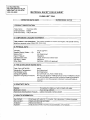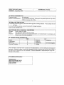
1
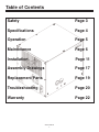
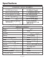
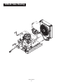
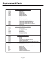
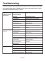
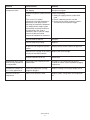
Owner’s Manual
Safety, Installation, Maintenance, and Operation
Model SRS-65
®
American Eagle, Inc.
190 State Street
PO Box 169
Garner, IA 50438
800-392-3015
Fax: 641-923-4889
www.americaneagleacc.com
Subject to Change without Notification.
© 2006 American Eagle
Manual Part No. 37246
Last Revision: 7/18/07
Introduction
American Eagle Compressors are designed to
provide safe and dependable service for a
variety of operations. With proper use and
maintenance, American Eagle Compressors will
operate at peak performance for many years.
necessary for product improvement or
commercial/production purposes. This right is
kept with no requirement or obligation for
immediate mandatory updating of this manual.
This product manual is not intended as a
training manual for beginners or unskilled
operators. This manual offers guidelines for
correct and safe usage of the compressor,
maintenance, and troubleshooting. If more
information is required or technical assistance is
needed, please contact AE Technical Support.
This manual contains information vital to the
safe use and efficient operation of this unit.
Following the information provided within this
manual can ensure the longevity of the
compressor. Carefully read and study the
operator’s manual before using the unit. Failure
to adhere to the instructions could result in
property damage or even serious bodily injury to
the operator or others close to the compressor.
Some sections of this manual contain
information pertaining to all American Eagle
manufactured compressors and may or may not
apply to your specific model.
A copy of this manual is provided with every
compressor and shall remain with the
compressor at all times. Information contained
within this manual does not cover all
maintenance, operating, or repair instructions
pertinent to all possible situations. This manual
is not binding. American Eagle reserves the
right to change, at any time, any or all of the
items, components, and parts deemed
If this manual becomes damaged, misplaced, or
unreadable at any point, or if you feel that any
part of this manual is unclear or incorrect,
please contact AE Technical Support at 800321-3741 or email at
[email protected]
For Technical Questions, Information, Parts, or Warranty, Call Toll-Free at
800-321-3741
Hours: Monday - Friday, 8:00 a.m. - 5:00 p.m. CST
Or email at the following addresses:
Technical Questions, and Information
[email protected]
Order Parts
[email protected]
Warranty Information
[email protected]
SRS-65 Manual
1
Table of Contents
Safety
Page 3
Specifications
Page 4
Operation
Page 5
Maintenance
Page 6
Installation
Page 11
Assembly Drawings
Page 17
Replacement Parts
Page 19
Troubleshooting
Page 20
Warranty
Page 22
SRS-65 Manual
2
Safety
This manual contains vital information for the safe use and efficient
operation of this unit. Carefully read the operators manual before
starting the unit. Failure to adhere to the instructions could result in
serious bodily injury or property damage.
The SRS-65 Rotary Screw Compressor will
provide safe and dependable service if operated
according to instructions. Read and understand
the safety precautions given in this manual and
on the decals attached to the shields. Failure to
do so can result in personal injury or equipment
damage.
Establish a training program for all operators to
ensure safe operation.
Do not operate the compressor unless
thoroughly trained or under the supervision of
an instructor.
Do not operate the compressor if it is damaged,
improperly adjusted or not completely or
properly assembled.
Operators and maintenance personnel must
always comply with the safety precautions.
These precautions are given here for your
safety. Review them carefully before operating
the compressor and before performing
maintenance or repairs.
Never operate the compressor with any of the
guards removed.
Do not attempt to adjust or disable the
compressors air pressure relief valve. This
valve limits the air pressure to 150 PSI.
Supervising personnel should develop additional
precautions relating to the specific work area
and local safety regulations.
The surface of the air compressor and the
plumbing between the compressor and the
cooler may reach temperatures above 150
degrees. Touching these surfaces during
operation can cause burns.
Precautions
Always wear safety equipment such as goggles,
ear plugs and head protection at all times when
operating the compressor.
Do not inspect or clean the compressor while
the power source is connected. Accidental
engagement of the tool can cause serious
injury.
The air taken in by the air compressor must be
free of flammable fumes and vapors.
Compressor speed should not exceed 8000
RPM.
Before performing any maintenance on the
compressor, place a warning tag on the
hydraulic power source or disconnect the hoses
from the compressor motor to prevent
accidental startup of the compressor.
Use and operate this air compressor only in full
compliance with all pertinent O.S.H.A.
requirements and all Federal, State and Local
codes or requirements.
Always connect hoses to the compressor before
energizing the power source. Be sure all hose
connections are tight.
SRS-65 Manual
3
Specifications
Compressor System Description
• 19-20 GPM Hydraulic System
• 2500 PSI System Pressure
• 2600 PSI Pressure Relief Setting
• 12 VDC Solenoid Control Valve
• All Steel Plumbing W/ JIC Fittings
• 6061 Aluminum Manifold
• 861 CFM, 12 Volt Cooler Fan
• Air Pressure Control Valve
• Belt Drive
• Max. Air Pressure 150 PSI
• Compressor RPM (small sprocket)
7000-7500 RPM
• 65 CFM @ 100 PSI With
Compressor Running @ 7000
RPM @ 20 GPM
General Information
• Model:
• Weight:
313 lbs.
• Cylinders:
• Delivery:
65 CFM @ 100 PSI
• Maximum Working Pressure:
150 PSI
• Relief:
2600 PSI
• Maximum Compressor Speed:
8000 RPM
• Delivery:
65 CFM @ 100 PSI (7000-7500 RPM)
• Dimensions:
29”L x 23”W x 22”H
• Electrical:
12 VDC
• Crankcase Oil Capacity:
5 Quarts
• Oil Reservoir Capacity:
Minimum: 26 Gallon Reservoir
SRS-65 Manual
4
Operation
Each compressor is bench tested under load at the factory to ensure proper break-in and operation.
While it is not necessary to follow any break-in procedure, the following checks should be made
before putting the unit into service and periodically during use.
Before Start-Up
Inspect unit for any visible signs of damage.
Check the oil level in the compressor with the dipstick on the unit. If oil is needed, use American
Eagle synthetic compressor oil (P/N C0087) or an equivalent synthetic oil. Note: There may be oil
left in the crankcase from the factory bench test. Overfilling may cause the compressor to
back blow oil. Always check the oil level and fill to the designated marking on the dipstick
before putting the unit into service.
Check hoses (air and hydraulic) for weak or worn condition and make sure that all connections are
secure.
Check the air intake filters on each head to make certain that they are clean and unobstructed.
Dirty air filters are a possible cause of reduced air output.
General Information
To use the compressor, start the vehicle engine
and engage the hydraulic system. The
compressor can now be activated using the
compressor switch. This energizes the hydraulic
solenoid sending oil to the hydraulic drive motor
and starts the compressor. Through the air
pressure switch and pilot valve, the system will
now function automatically. Once engaged,
adjust the engine speed control to ensure that
the compressor speed does not exceed 8000
RPM under load. Adjustment instructions are
provided with the speed control unit.
compressor to pump air. See head unloading
system for detailed views and adjustment
instructions on the next page.
Operating Notes:
This reciprocating compressor must not be used
for breathing air. To do so will cause serious
injury whether air is supplied direct from the
compressor source or to breathing tanks for
later use. Any and all liabilities for damage or
loss due to injuries, death and/or property
damage, including consequential damages
stemming from the use of this compressor to
supply breathing air will be disclaimed by the
manufacturer.
Air Pilot Valve Operation
(Head Unloading System)
When the hydraulic system is engaged the
compressor will pump air into the receiver until
the pressure reaches 150 psi. At this time the
air pilot valve senses the pressure in the
receiver and engages an intake valve hold-open
mechanism. The compressor will run free until
the pressure in the receiver falls below 115 psi
and the air pressure valve disengages the
intake valve hold-open mechanism to allow the
The use of this compressor as a booster pump
and/or to compress a medium other than
atmospheric air is strictly non-approved and can
result in equipment damage and/or injury. Nonapproved uses will also void the warranty.
Never use plastic pipe or improperly rated
metal pipe. Improper piping materials can burst
and cause injury or property damage.
SRS-65 Manual
5
Maintenance
The following table is a list of routine maintenance items, including service intervals. Service
intervals are listed as hours, days, or weeks, whichever occurs first. American Eagle recommends
that these service intervals be followed. Before performing any maintenance function “Lock Out” or
“Tag Out” all sources of power. Be sure all air pressure in unit is relieved. Failure to do so may
result in injury or equipment damage.
Service Intervals
Maintenance operation
Daily
Weekly
Monthly
Hourly
Drain air tanks
Check crankcase oil level
Check fittings and airlines
Check hydraulic fluid level
Inspect and clean air intake filters
Clean and operate safety valves
Clean cooling fins on radiator/cooler
Inspect check valve
12
Replace Coalescering/Separator Cartridge
Inspect and clean compressor valves
Replace hydraulic filter
6
Replace air filters/oil filter/compressor oil
3
Tighten all fittings and fasteners
3
Check all electrical connections
3
6
250
Inspect and clean air check valve
Under normal operating conditions, oil changes are required every 3 months. When operating in a
dirty environment, change the oil more frequently as your particular operating condition dictates.
USE AE SYNTHETIC COMPRESSOR OIL P/N C0087.
COMPRESSOR CRANKCASE CAPACITY IS 4 QUARTS.
General preventative maintenance includes maintaining proper fluid level in both systems and the
general cleanliness of the equipment. Proper fluids according to the specifications are required.
SRS-65 Manual
6
SRS-65 Oil Level
The oil level in the oil receiver container is an important factor for the operational reliability of the system.
Check Intervals:
1. Before starting unit.
2. Every 100 operating hours
Check Procedures:
1. Switch off the unit with main power and prevent it from accidentally being turned on.
2. Allow one full minute to pass after stopping compressor.
3. Unscrew the cap of the inlet connection pipe with the oil receiver discharged.
4. Check the oil level with the dipstick.
5. Add oil to level if necessary.
6. Tighten cap back into place and unit is ready to be put into service
7. Check for impermeability and replace the o-ring if required.
Note:
• The screw-type cap of the compressor crankcase is equipped with a pressure release hole, which
emits air/oil if the pressure has not been alleviated from the separator receiver. In this case wait a few
minutes for the pressure to release before removing cap totally.
• The oil fill is designed in such a way that the unit cannot be over filled. Any excess oil runs out the fill.
Condensation Drain
The condensation in the oil affects the operation safety and the life of the screw compressor unit.
If you operate the screw compressor unit for a short period of time and therefore at a low operation
temperature, i.e. below the switch temperature of the thermal oil bypass valve, you run the risk of
condensation collecting in the oil separator receiver. The relative humidity in the intake air determines the
quantity of condensation.
Possible Malfunctions:
• Insufficient compressor lubrication.
• Insufficient air/oil separation and high differential pressure in the purifier cartridge.
• Corrosion and rust formation due to condensation in the oil.
Drain the condensation regularly when the compressor unit is cold prior to startup.
Maintenance Procedure:
1. Switch off the main power to the unit.
2. Slowly unscrew the oil fill cap.
3. Unscrew the oil drain plug carefully and place a container underneath.
4. Drain the condensation from the separator receiver until oil starts to come out. Then replace the drain
plug.
5. Fill separator receiver with oil up to maximum, then close oil fill.
6. Switch on compressor and run for 3 minutes.
7. Check oil level and fill if necessary.
8. Dispose of condensation in accordance with local and federal regulations.
SRS-65 Manual
7
Changing the Oil
WARNING
You may change the unit oil only when the unit
has been stopped and completely discharged.
Note: Prior to changing the unit oil make sure the unit has an operating temperature 140-175°F
(60-80°C).
Maintenance Procedure:
1. Switch off the main power to the unit.
2. Slowly unscrew the oil fill cap.
3. Unscrew the oil drain plug carefully and place
a container underneath.
4. Drain the oil from the separator receiver until
oil stops draining out. Then replace the drain
plug.
5. Refill separator receiver with oil up to
maximum, then close oil fill.
6. Switch on compressor and run for 3 minutes.
7. Check oil level and fill if necessary. Oil
capacity is 5 quarts.
OIL FILL
OIL DRAIN
Oil Recommendation
Oil Requirements
Screw compressors must be operated using the most
suitable oil for operation. The compressor manufacturer
must approve this oil for use. The oil must also be
suitable for use in unfavorable conditions such as:
contamination of the intake air by gases, solvent vapors,
exhaust gases, and high ambient temperature
conditions.
High aging stability
Suitable types and brands of oil may be specified on
request. Suitable screw compressor oils can be mineral
oils, synthetic oils, and biological degradable oils.
Pour-point: 5° below lowest ambient temperature
minimum
High disperse capacity
Low emulsification tendency
Flash point: above 400°F/ 200°C
Minimum foaming
The substances and materials used in the compressor
such as seals must be taken into account when
selecting the types of oil. Corrosion or other material
degradation must not occur.
High corrosion protection
Important: Do not mix different types of oil.
Basic oil: solvate
Important: In the case of ambient temperatures close to
freezing, prevent the unit from freezing.
Operating temperature: up to 230°F / 110°C
Hydraulic or turbine oil
Viscosity class: ISO VG 68
Pipeline Materials:
The oil used in screw compressors can degrade plastics
used in air pipelines.
Viscosity at 104°F / 40°C: ca. 42-50 mm2/s (cST)
SRS-65 Manual
8
Oil Filter
The oil filter is located in front of the unit. Replace it after the first 50 hours of service.
Then replace it every 1000 hours of service after that (or as soon as differential pressure
is about 25 psig)
Maintenance procedure:
1. Switch off the main power to the unit. Fully relieve the unit
of pressure.
2. Slowly unscrew and remove the oil filter with an oil filter
wrench.
3. Grease the new filter gasket.
4. Before mounting the new filter hold it upright and fill it with
the same type of oil as the compressor crankcase.
5. Thread the new filter onto the compressor by hand without
any tools.
6. Run compressor for 3 minutes.
7. Check oil level and fill if necessary.
Oil Filter
P/N 15323
Separator Cartridge
The separator cartridge is disposable and is located on top of the filter support.
The cartridge has to be replaced at least once per year and at a maximum of 5000 operating hours. The pressure will
read above 14 psig. If intake air is often contaminated or the oil quality is poor, the cartridge will tend to clog earlier
and will need changed more often.
Maintenance Procedure:
1. Switch off the main power to the unit. Fully relieve the unit
of pressure.
2. Slowly unscrew and remove the cartridge with an oil filter
wrench.
3. Screw the new cartridge onto the filter support using only
your hands.
4. Write the date of change, and the operating hours on the
cartridge.
5. Check to make sure that the cartridge is tight.
6. Run compressor for 3 minutes.
7. Check cartridge to make sure it is tight.
SEPARATOR
CARTRIDGE
P/N 15324
Intake Filter
The air intake filter element shall be replaced every 100 hours of running time. The filter may require changing more
often if the air pollution level is higher.
Maintenance Procedure:
1. Switch off the main power to the unit. Protect the unit from
accidental re-start.
2. Open the filter lid and carefully remove dust and debris
from the intake tray.
3. Carefully remove old filter and clean or renew it.
• Clean the filter by knocking the filter against your hand.
• Clean the filter with compressed air.
4. Close filter lid.
5. Test run the compressor to ensure proper installation.
ATTENTION: Any dirt or debris that reaches the intake
will be ingested into the compressor and could cause
irreversible damage.
SRS-65 Manual
9
FILTER LID
AIR FILTER
P/ 15322
Belt Tension
Belt Deflection
NEW BELT
INSTALLATION TENSION: 98.0 lbf
TENSIONING FORCE: 6.8 lbf
BELT DEFLECTION: 9/64 in
SPAN LENGTH: 9.50 in
Force Applied
USED BELT
INSTALLATION TENSION: 65.4 lbf
TENSIONING FORCE: 4.8 lbf
BELT DEFLECTION: 9/64 in
SPAN LENGTH: 9.50 in
Span
Minimum Pressure Valve
At the factory, the relief valve is set at 64psi. When servicing the screw compressor a check of the
minimum pressure may be necessary.
Minimum Pressure Readjustment Procedure:
1. Remove the locknut.
2. Turn the adjusting screw (turning the screw in
increases the pressure).
3. Tighten locknut in place.
LOCK NUT
ADJUSTING SCREW
Hydraulic Oil Cooler/Compressor Oil Cooler
For the operational safety of the unit clean the cooler regularly. Keep the cooling fins clean, this is
a must to achieve maximum cooling from your cooler. Adequate cooling will prolong the life of your
screw compressor. To clean your cooler use compressed air, steam jet, or a cleaning agent.
Maintenance Procedure:
1. Switch off the main power to the unit. Protect the
unit from accidental re-start.
2. Remove cooler housing.
a. Discharge unit.
b. Drain oil.
c. Remove cooler.
3. Clean and remove dirt.
4. Reassemble parts onto unit.
5. Check and fill oil level.
6. Test run the compressor to ensure proper
installation and recheck oil level.
SRS-65 Manual
10
Oil Cooler
Installation
COMPONENT INSTALLATION
This section pertains to the installation of the air compressor, PTO, pump and other related items.
The instructions are intended as a guide to assist you with particular installation. These instructions
will provide only general information.
Pump Assembly:
The pump assembly may either be installed
directly on the PTO or as an optional
method, may be driven by a driveline from
the PTO. Pump manufacturers provide
specific installation information for their
products and should be consulted if
questions arise. Note: A Dual or Tandem
Hydraulic Pump is recommended when
additional hydraulically operated equipment are
added to the hydraulic system.
Electrical Connections:
From the air pressure switch there are two
(2) wires, red and black, running to the
outside of the compressor housing. Connect
the black wire to the vehicle frame or other
suitable ground. Mount a single throw
toggle switch in a convenient location and
connect the red wire from the compressor to
this switch. Connect the other switch
terminal to a fuse holder and then to a 12volt power supply. A third wire is required
from the air compressor switch when
connecting the speed control into the
system. (See drawing on next page)
PTO Assembly:
Check with the PTO manufactures
representative for specific instructions
regarding your particular make, model, and
year of vehicle. As some trucks may require
modification of the transmission cross
member and the exhaust system, the
manufacturer’s instructions should be
followed to insure proper installation of the
PTO.
Electric Speed Control:
An optional electric or electronic speed
control must be used to maintain proper
operating speed of the air compressor. The
engine speed control will automatically
increase from idle to preset speed when
engaged and decrease when disengaged.
FAN
Compressor Assembly:
Prepare the mounting location of the
compressor by locating and drilling four (4)
holes, 1/2” diameter as per the mounting
pattern of the air compressor base. Using
four (4) 3/8” x 1.25 GR-5 cap screws, 3/8”
flat washer, and 3/8” nyloc nut, secure the
compressor in place. The compressor is air
cooled, and must have a clean supply of
cooling air to the fan with minimum
restrictions. Adequate space must be
provided for proper circulation of air.
GND
LINE
CPRSR
MOTOR
SPD CTRL
PRESSURE
SWITCH
C
B
A
SRS-65 Manual
11
HYDRAULIC
MANIFOLD
C
B
A
COMPRESSOR (12V INPUT)
GROUND
SPEED CONTROL
SRS-65 Electrical Installation
RED WIRE
(NOT USED)
RED WIRE
(NOT USED)
BLACK WIRE
Temperature Gauge Installation
USE THIS PORT FOR
THE TEMP GAUGE
PROBE
DO NOT ATTEMPT TO INSTALL
TEMPERATURE GAUGE INTO THIS
PORT. DAMAGE WILL RESULT!
SRS-65 Manual
12
Component Installation Continued...
PRESSURE LINE
AIR DELIVERY
RETURN LINE
Hydraulic System:
The hydraulic system consists of the pump, oil reservoir, filters and hoses. Installed on the
compressor is a valve block assembly that controls the flow to the hydraulic motor. To this
block, a 1/2” high-pressure hose must be attached. This hose comes from the hydraulic pumps
pressure side. A 3/4” minimum low-pressure return line is connected to the oil cooler outlet and
is routed to the oil reservoir. American Eagle recommends a sufficient sized reservoir be
provided that includes the proper suction and return filters. The cooler on the compressor is
designed and sized to cool the air compressor efficiently. An auxiliary oil cooler is required
when additional hydraulically operated equipment are added to the hydraulic system. Pressure
on the return line exceeding 200 PSI can and will cause damage to the filter, cooler, and
components of the compressor hydraulic system.
Air System:
The airline is routed using a 3/4” (200 psi) air hose. This delivery line should be free
from all obstructions. When connecting to an air tank (American Eagle recommends a
minimum of a ten gallon air tank be installed to maintain proper operation of the air
compressor), a check valve must be installed.
General Install Note:
When installing any air compressor, good manufacturing processes should be used. It
is critical to allow for proper air circulation around the compressor assembly and all
heated air should be allowed to exhaust to the outside if the compressor is mounted in
an enclosed compartment. Maximum operating temperatures of the air compressor
should not be exceeded.
SRS-65 Manual
13
Compressor Pressure Switch
Kick Out (Step 1)
Pressure Setting
Adjustment Screw
(145-150 psi)
-
+
-
+
Kick On (Step 2)
Pressure Setting
Adjustment Screw
(115-120 psi)
Note: Turning adjustment screws clockwise
increases psi settings. Turning adjustment screws
counterclockwise decreased psi settings.
Location inside box of SRS Compressors
Pressure Setting Instructions:
1. Always set the kick out pressure setting first. 145 psi minimum/150 psi maximum.
2. After kick out pressure is set, adjust the kick on screw setting at 115 psi minimum/120 psi
maximum.
3. Cycle compressor to verify correct settings.
4. For questions about this procedure, please contact Stellar Customer Service (Page 1).
SRS-65 Manual
14
Typical Hydraulic Circuit for Single Stage Pump with
PN 30533
Multiple Components
Typical Hydraulic Circuit for Tandum
(Two Part) Pump with
PN 30532
Multiple Components
SRS-65 Manual
15
Typical Hydraulic Circuit for Compressor
with Auxiliary Cooler
HYDRAULIC
RESERVOIR
FILTER
FILTER SCREEN
AUXILIARY
COOLER
SUCTION PORT
SINGLE
HYDRAULIC
PUMP
COMPRESSOR
RETURN
PRESSURE
SRS-65 Manual
16
Assembly Drawings
Compressor Assembly
72
74
11
21
47
23
24
7
27
42
73
54
58 59
11
4
3
34
71
9
19
18
76
75
8
64
5 77
10
11
1
30
8
12
PART
31028
29391
17583
0523
C3075
C0910
0343
0333
C1180
27 72
C2142
C4914
C 4913
C6 1 4 5
22860
13579
12856
C0078
0479
21393
301 54
3 1 03 2
0485
0 5 22
5735
8 2 41
29
50
20
13
ITEM
1
2
3
4
5
6
7
8
9
10
11
12
13
14
15
16
17
18
19
20
21
22
23
24
25
26
40
53
36
7
33
22
38
56
15
34
39
35
37 48
16
49
68
43
55
17
31
32
51
69
15
57
44
26
2
34
45
34
70
41
66
52
46
19
63
67
25
28
57 65
60
61
8
64
63
62
14
6
QTY. ITEM PART DESCRIPTION
DESCRIPTION
QTY. ITEM PART DESCRIPTION
27 0521 WASHER 0.25 LOCK
4
BASE WLDMT CPRSR SRS65
1
53 33695 TUBE ASM 0.50 CPRSR/THERMVLV SRS65
28 19589 NUT SERT 0.25-20X0.38 OD
4
CPRSR SRS NK60-2 ROTORCOMP
1
54 21300 FTG 90 MJIC/MBSPP 12-8C40M
29 12122 BOLT 0.38X1.00 EYE 567-23-ZN
1
CAP SCR 10MMX30MM HHGR5
4
55 C0863 SWITCH PRES COMPRESSOR
WASHER 0.38 LOCK
4
30 0535 NUT .38-16 HH
1
56 8277 FTG ST L 0.25 MNPT/0.125 FNPT SPL
31 21400 FTG SWIVEL NUT/MSTR .50 8F65OX
1
57 C6245 ELBOW 0.25 OD BRASS AIR
BLOCK AL CPRSR SHD 66
1
CAP SCR 0.25-20X2.75 HHGR5
2
32 21299 FTG ADAPT MBSPP/MJIC 8-8M40M
1
58 8158 NIPPLE 0.25 X CLOSE BRASS
1
WASHER 0.31 USS FLAT ZINC
10 33 22018 VALVE THERMO R-2323 SRS40
59 21298 FTG ADAPT MBSPP/FNPT 1/4-1/4 F4OHG
NUT 0.25-20 HHGR5 NYLOC
5
34 21297 FTG 90 MBSPP/MJIC 8-8C4MX
4
60 21549 PANEL GAUGE MNT SRS40
FTG ADAPT 8-12 F5OLO-S
1
35 30667 BRKT MOTOR MNT SRS65
1
61 21649 GAUGE AIR SWICHGAGE PSB20PHL200
1
1
CAP 8FNL-S
62 21650 GAUGE OIL TEMP TSB20TVD3006125SR240
36 31042 BUSHING H X 35MM
37 34538 SPROKET GOODYEAR EAGLE PD Y-36S-H
1
FTG ADAPT ML O'RING/ML 12-F5OLO-S
3
63 C6021 CAP SCR 0.25-20X0.75 BTNHD SS
1
VALVE RELIEF CP-200-1-B-0-A-C
1
64 0340 WASHER 0.25 FLAT
38 C6188 BUSHING 1.00
VALVE SOLND
1
39 34539 SPROKET GOODYEAR EAGLE PD Y-90S-QD
1
65 22161 COUPLER 0.13 BRASS
1
40 31043 BELT GOODYEAR EAGLE PD Y1000
1
F T G 9 0 DE G
66 5419 FTG 0.50-0.25 BUSH RED BRASS
FTG ADAPT MBSPP/FNPT 1/2-1/2 F4OHG MOD 2
67 C5504 VALVE RELIEF 200#
41 31035 MOTOR HYD PLM3022SO-33S5-LOD/OF-N-C
1
NIPPLE 0.50X2.50 BRASS 80300-0825
1
42 C2269 FTG ADAPT 12-16 F5OLO
1
68 26025 CAP SCR 0.50-13X2.25 HHGR5
CAP 0.50 PIPE HEX 5406-8
43 7351 FTG ST TH ELBOW 45 DEG 12V5OLO
1
1
69 0352 WASHER 0.50 USS FLAT ZINC
HOSE CLAMP #8 RUBBER COATED
1
70 C6106 NUT 0.50-13 HHGR5 NYLOC
44 C4498 FTG ORB/JIC STRT CONNT 12-F5OX-S
1
71 4591 PLUG STR HOLLOW HEX 0.75 12-HP5ON
CAP SCR 0.25-20X0.75 HHGR5
5
45 4594 FTG STRGHT THRD CONNECT 8F5OX
1
FTG BULKHEAD 12WGTX-WLN
1
46 4593 FTG SWIVEL NUT TEE 8R6X
1
72 31422 SHROUD ASM SRS65
COOLER OIL ASM SRS65
73 19592 WASHER 0.25 FLAT NYLON
1
47 33715 HOSE 0.75(381-JC-J9-12-12-12-13.00)
1
74 9804 DECAL SRS-65
SHROUD SRS65 FAN MNT
1
48 33716 HOSE 0.75(381-JC-JC-12-12-12-14.00)
1
CAP SCR 0.31-18X1.25 HHGR5
4
49 33691 TUBE ASM 0.75 COOLER/MANIFOLD SRS65
1
75 31030 ANGLE MNT FRONT CPRSR SRS65
WASHER 0.31 LOCK
4
76 0480 CAP SCR 0.25-20X1.00 HHGR5
50 33692 TUBE ASM 0.75 AIR/BULKHEAD SRS65
1
77 0342 NUT 0.31-18 HH NYLOC
NUT SERT 0.31-18X0.50 OD
4
51 33693 TUBE ASM 0.50 COOLER/THERMVLV SRS65
1
1
52 33694 TUBE ASM 0.50 CPRSR/COOLER SRS65
1
FAN 16.00 PUSH 12 VOLT
78 C6072 BOSCH RELAY
79 19590 WIRING HARNESS
SRS-65 Manual
17
QTY.
1
1
1
1
2
1
1
1
1
1
8
6
1
1
1
2
4
2
1
1
6
2
1
2
2
1
1
SRS-65 Tube Routing
SRS-65 Manual
18
Replacement Parts
PART#
C4914
C4913
31035
34539
34538
C6188
31043
30154
C3075
33692
33691
33693
33694
33695
22018
PART#
C0863
8241
C6072
19590
21649
21650
C5504
HYDRAULIC COMPONENTS/DRIVE PARTS
DESCRIPTION
Relief Valve
Solenoid Valve
Hydraulic Motor
Sprocket (Hyd Motor)
Sprocket (Compressor)
Bushing (Hyd Motor)
Belt
Oil Cooler
Aluminum Manifold Block
Tube Assembly Air/Bulkhead 0.75
Tube Assembly Cooler/Manifold 0.75
Tube Assembly Cooler/Thermo-Valve 0.50
Tube Assembly Compressor/Cooler 0.50
Tube Assembly Compressor/Thermo-Valve 0.50
Thermo Valve
ELECTRICAL/AIR PRESSURE COMPONENT
DESCRIPTION
Pressure Switch
Fan 16.00” Pull 12 Volt
Bosch Relay
Wire Harness
Air Switch Gauge
Oil Temperature Gauge
Valve Relief 200 # (Air)
PART#
15322
15323
15324
C0087
33147
AIR/OIL FILTER COMPONENTS
DESCRIPTION
Air Filter
Oil Filter
Coalescering Filter (Separator Cartridge)
Synthetic Compressor Oil
SRS65 Compressor Service Kit (Includes all items above)
PART#
NA
NA
NA
NA
NA
29391
NA
COMPRESSOR COMPONENTS
DESCRIPTION
Inlet Solenoid Control Valve
Inlet Solenoid Control Valve Assembly Complete
Shaft Seal Kit
Shaft Bearing Kit
Solenoid 24 Volt DC
Compressor (Air End)
Separator Head Maintenance Kit
SRS-65 Manual
19
Troubleshooting
If symptoms of poor performance develop, the following chart can be used as a guide to investigate
and correct the problem. When diagnosing faults in operations of the air compressor, always check
that the hydraulic power source is supplying the correct hydraulic flow and pressure that is listed in
the compressor specification section of this manual.
Solution
Problem
Possible Cause
Compressor shuts down
with air demand:
Compressor temperature.
Low oil level.
Add compressor oil to level.
Fan not operating.
Check ground wire and fan switch/relay.
Plugged oil filter.
Replace filter.
Dirty cooler core.
Clean cooler fins.
Contaminated cooler core.
Remove and clean.
Hydraulic pressure and flow incorrect. Adjust and reset according to specifications.
Compressor will not build
up pressure:
Worn hydraulic motor.
Replace.
Air demand too great.
Tighten air hose clamps. Repair air leaks.
Air filter plugged.
Clean or replace.
Pressure switch out of adjustment
Readjust to specifications.
Faulty pressure switch.
Replace.
Compressor speed too slow.
Check hydraulic flow and pressure.
Drive belt slipping.
Readjust and tighten.
Service valve wide open.
Close valve.
Solenoid valve on.
Compressor over
pressures:
Hyd. manifold valve stuck (closed).
Clean or replace.
Defective pressure switch.
Replace.
Air control line leaking.
Check and correct.
Inlet valve stuck.
Clean and replace.
Restriction in control line (dirt/ice).
Clean and free up.
SRS-65 Manual
20
Problem
Possible Cause
Solution
Compressor Stalls:
Belt Slipping.
Readjust and tighten.
Insufficient hydraulic system pressure
or flow.
Check the following:
1. Setting on supply pressure system relief
valve.
2. Ensure adequate pressure and flow.
3. Check and see if other hydraulic system’s
activated off same hydraulic supply.
*This can occur if another
hydraulically activated component is
used off the same pump system.
Activating the secondary component
may drop hydraulic supply system
pressure/flow and leave insufficient
for compressor. Not: Even a
momentary drop in hydraulic supply
pressure or flow may initiate
compressor blowdown to commence.
Pressure relief set too low.
Readjust.
Pressure relief seals leaking.
Replace.
Air pressure set to high for hydraulic
system.
Adjust pressure switch to reduce air pressure.
Solenoid valve cartridge seals leaking
on hydraulic manifold assembly.
Replace with new cartridge.
Hydraulic reservoir low on oil.
Add to level.
Compressor noisy or loud
when starting compressor
in cold weather:
ICE buildup inside compressor from
condensation.
Engage PTO and allow hydraulic fluid to
circulate and warm system up before engaging
compressor.
Compressor synthetic oil
has a milky appearance:
Coalescering/Separator cartridge
clogged or plugged.
Replace cartridge and change compressor oil.
Excessive oil level in
compressor:
Internal crack inside oil cooler.
Replace cooler, change filters and compressor
oil.
SRS-65 Manual
21
®
Limited Warranty Statement
American Eagle warrants products designed and manufactured by Stellar to be free from defects in material and workmanship under proper use
and maintenance. Products must be installed and operated in accordance with Stellar’s written instructions and capacities. The warranty period
shall cover the following:
Twelve (12) month warranty on parts and
Twelve (12) month repair labor
The warranty period shall begin from the date recorded by American Eagle as the in-service date. This date will be derived from the completed
warranty registration card. In the event a warranty registration card is not received by American Eagle, the factory ship date will be used. New
compressors will be issued on all returns within 90 days of this factory ship date. After 90 days, American Eagle reserves the right to issue
remanufactured compressors. Regardless of in-service date, warranty coverage does not extend beyond twenty-four (24) months from date of
manufacture.
American Eagle’s obligation under this warranty is limited to, and the sole remedy for any such defect shall be, the repair and/or replacement (at
American Eagle’s option) of the unaltered part and/or component in question. American Eagle after-sales service personnel must be notified by
telephone, fax, or letter of any warranty-applicable damage within fourteen (14) days of its occurrence. If at all possible, American Eagle will ship
the replacement part within 24-hours of notification by the most economical, yet expedient, means possible. Expedited freight delivery will be at
the expense of the owner.
Warranty claims must be submitted and shall be processed in accordance with American Eagle’s established warranty claim procedure. American
Eagle after-sales service personnel must be contacted prior to any warranty claim. A return materials authorization (RMA) account number must
be issued to the claiming party prior to the return of any warranty parts. Parts returned without prior authorization will not be recognized for
warranty consideration. All damaged parts must be returned to American Eagle freight prepaid; freight collect returns will be refused. Freight
reimbursement of returned parts will be considered as part of the warranty claim.
Warranty service will be performed by any American Eagle new equipment distributor, or by any American Eagle-recognized service center
authorized to service the type of product involved, or by the American Eagle factory in the event of a direct sale. At the time of requesting
warranty service, the owner must present evidence of date of delivery of the product. The owner shall be obligated to pay for any overtime labor
requested of the servicing company by the owner, any field service call charges, and any towing and/or transportation charges associated with
moving the equipment to the designated repair/service provider.
All obligations of American Eagle and its authorized dealers and service providers shall be voided if someone other than an authorized American
Eagle dealer provides other than routine maintenance service without prior written approval from American Eagle. In the case repair work is
performed on a American Eagle-manufactured product, original American Eagle parts must be used to keep the warranty in force. The warranty
may also be voided if the product is modified or altered in any way not approved, in writing, by American Eagle.
The owner/operator is responsible for furnishing proof of the date of original purchase of the American Eagle product in question. Warranty
registration is the ultimate responsibility of the owner and may be accomplished by the completion and return of the American Eagle product
registration card provided with the product. If the owner is not sure of registration, he is encouraged to contact American Eagle at the address
below to confirm registration of the product in question. This warranty covers only defective material and workmanship. It does not cover
depreciation or damage caused by normal wear and tear, accident, mishap, untrained operators, or improper or unintended use. The owner has
the obligation of performing routine care and maintenance duties as stated in American Eagle’s written instructions, recommendations, and
specifications. Any damage resulting from owner/operator failure to perform such duties shall void the coverage of this warranty. The owner will
pay the cost of labor and supplies associated with routine maintenance.
The only remedies the owner has in connection with the breach or performance of any warranty on the American Eagle product specified are
those set above. In no event will American Eagle, the American Eagle distributor/dealer, or any company affiliated with American Eagle be liable
for business interruptions, costs of delay, or for any special, indirect, incidental, or consequential costs or damages. Such costs may include, but
are not limited to, loss of time, loss of revenue, loss of use, wages, salaries, commissions, lodging, meals, towing, hydraulic fluid, or any other
incidental cost.
All products purchased by American Eagle from outside vendors shall be covered by the warranty offered by that respective manufacturer only.
American Eagle does not participate in, or obligate itself to, any such warranty.
American Eagle reserves the right to make changes in design or improvement upon its products without imposing upon itself the same upon its
products theretofore manufactured.
This warranty will apply to all American Eagle Drawer Sets and Compressed Air Systems shipped from American Eagle’s factory after July 1,
2005. The warranty is for the use of the original owner only and is not transferable without prior written permission from American Eagle.
THIS WARRANTY IS EXPRESSLY IN LIEU OF ANY OTHER WARRANTIES, EXPRESS OR IMPLIED, INCLUDING ANY WARRANTY OF
MERCHANTABILITY OR FITNESS FOR A PARTICULAR PURPOSE. REMEDIES UNDER THIS WARRANTY ARE LIMITED TO THE
PROVISION OF MATERIAL AND SERVICES, AS SPECIFIED HEREIN. AMERICAN EAGLE INDUSTRIES, INC. IS NOT RESPONSIBLE FOR
INCIDENTAL OR CONSEQUENTIAL DAMAGES.
Revision Date: March 2006
Document Number: 37042