1
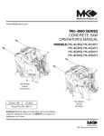
MK-4000 SERIES
CONCRETE SAW
OPERATOR’S MANUAL
www.mkdiamond.com
MODELS: MK-4000KB/G Series
MK-4000HY/G Series
Single Speed
Three Speed
MK-4036HY
Hyundai
Gas Engine
Revision 108
12.2013
Manual Part No. 168118
Caution: Read all safety and operating instructions
before using this equipment. This parts list MUST
accompany the equipment at all times.
INTRODUCTION
Congratulations on your purchase of a MK-4000 Concrete Saw. We are certain that you will be
pleased with your purchase. MK Diamond takes pride in producing the finest construction power
tools and diamond blades in the industry.
Operated correctly, your MK-4000 Concrete Saw should provide you with years of service. In order
to help you, we have included this manual. This owners manual contains information necessary to
operate and maintain your MK-4000 Concrete Saw safely and correctly. Please take the time to familiarize yourself with the MK-4000 Concrete Saw by reading and reviewing this manual.
Read and follow all safety, operating and maintenance instructions.
If you should have questions concerning your MK-4000 Concrete Saw, please feel free to call our
friendly customer service department at: 800 421-5830
Regards,
MK Diamond
NOTE THIS INFORMATION FOR FUTURE USE:
MODEL NUMBER:
SERIAL NUMBER:
PURCHASE PLACE:
PURCHASE DATE:
NOTE: For your (1) one year warranty to be effective, complete the warranty card (including the Serial Number) and mail it in as soon as possible.
2
TABLE OF CONTENTS
SAFETY Safety Message/Alert Symbols Safety Warnings
Rules for Safe Operation & Transportation
Operation & Safety Decals
Safety Decal Locations
Console Controls
Console Control Descriptions
PAGE NO.
5
6
7-8
9-10
11
12
12
PRODUCT SPECIFICATIONS
Specifications
Saw Features
Model Specifications
Instructions for Changing Blade Speed
Single Speed
Gear Box
13-15
15
15
16
17
17
INSPECTION & START-UP
Pre-Operation Checklist, Belt & Powerband
Schedule Maintenance Quick Reference
18
19
OPERATION
20-21
Blade Mounting Instructions
22
Starting Engine, Starting Instructions
Saw Guide Alignment and Adjustment, Pointer Alignment
23
Maneuvering the Saw, Dry Cutting, Wet Cutting, Speed Control-Lever Use and Adjustment
24
25
Engaging the Drive Unit, Water Hook Up
Depth Indicator and Depth Stop
26
MAINTENANCE
Engine, Air Cleaner, Arbor, Axle, Drive Unit, & Hydrostatic Drive Unit
Maintenance Schedule
Troubleshooting
27
28
29
GENERAL PRODUCT INFORMATION
Ordering, Return & Packaging Contact Information and Limited Warranty 30
31
3
MK-4000 SERIES
SAFETY
Safety precautions should be followed at all times when operating this equipment. Failure to read and
understand the Safety Precaution and Operating Instructions could result in injury to yourself and
others.
This Operation Manual has been developed to provide complete instructions for the safe and efficient
operation of the MK-4000 Concrete Saw.
Before using this saw, ensure that the person operating the equipment has read and understands all
instructions in this manual.
SAFETY MESSAGE / ALERT SYMBOLS
A safety message alerts you to potential hazards that could hurt you or others. Each safety message is
preceded by a safety alert symbol (
) and one of three words: DANGER, WARNING, or CAUTION.
DANGER
You WILL be KILLED or SERIOUSLY INJURED if you do not follow directions.
WARNING
You CAN be KILLED or SERIOUSLY INJURED if you do not follow directions.
CAUTION
You CAN be INJURED if you do not follow directions. It may also be used
to alert against unsafe practices.
Each message tells you what the hazard is, what can happen, and what you can do to avoid or
reduce injury. Other important messages are preceded by the word NOTICE.
NOTICE
You can cause PROPERTY DAMAGE to your machine if you don’t follow directions.
The safety labels should be periodically inspected and cleaned by the user to maintain good legibility
at a safe viewing distance. If the label is worn, damaged or illegible, it should be replaced. Contact
MK Diamond or your dealer for replacement.
4
MK-4000 SERIES
SAFETY
SILICA DUST WARNING
Grinding/cutting/drilling of masonry, concrete, metal and other materials with silica in their composition
may give off dust or mists containing crystalline silica. Silica is a basic component of sand, quartz,
brick clay, granite and numerous other minerals and rocks. Repeated and/or substantial inhalation of
airborne crystalline silica can cause serious or fatal respiratory diseases, including silicosis. In addition, California and some other authorities have listed respirable crystalline silica as a substance
known to cause cancer. When cutting such materials, always follow respiratory precautions.
CALIFORNIA PROPOSITION 65 MESSAGE
Some dust created by power sanding, sawing, grinding, drilling, and other construction activities contain chemicals known (to the State of California) to cause cancer, birth defects or other reproductive
harm. Some examples of these chemicals are:
• Lead, from lead-based paints
• Crystalline silica, from bricks and cement and other masonry products
• Arsenic and chromium, from chemically treated lumber
For further information, consult the following sources:
http://www.osha.gov/dsg/topics/silicacrystalline/index.html
http://www.cdc.gov/niosh/docs/96-112/
http://oehha.ca.gov/prop65/law/P65law72003.html
http://www.dir.ca.gov/Title8/sub4.html
((
Your risk from these exposures varies depending on how often you do this type of work. To reduce
your exposure to these chemicals, work in a well-ventilated area, and work with approved safety
equipment, such as dust masks that are specially designed to filter out microscopic particles. Where
use ON
of a dust) extraction device is possible, it should be used. To achieve a high level of dust collec)
tion, use an industrial HEPA vacuum cleaner. Observe OSHA 29 CFR part 1926.57 and 1926.103.
WARNING
Sawing and drilling generate dust. Excessive airborne particles may cause irritation to eyes, skin and
respiratory tract. To avoid breathing impairment, always employ dust controls and protection suitable
to the material being sawed or drilled; See OSHA (29 CFR Part 1910.1200).
5
MK-4000 SERIES
SAFETY
RULES FOR SAFE OPERATION
DANGER
Failure to follow instructions in this manual may lead to serious injury or even death! This equipment
is to be operated by trained and qualified personnel only! This equipment is for industrial use only.
The following safety guidelines should always be used when operating the MK-4000 Concrete Saw.
MAINTENANCE SAFETY
• NEVER lubricate components or attempt service on a running machine.
• Keep the machinery in proper running condition. Clean the machine after each day’s use. Follow instructions for changing accessories. Inspect tool periodically and, if damaged, have repaired by authorized service facility.
SET UP & TRANSPORTATION SAFETY
• ALWAYS use caution and follow the instructions when lifting and transporting this machine.
• ALWAYS tie down the machine when transporting. DO NOT tow this machine behind a vehicle.
• NEVER transport with the blade mounted on the machine.
• Lift only from the lift bail.
GENERAL SAFETY
•
DO NOT operate or service this equipment before reading this entire manual.
Read and understand all warnings, instructions and controls on the machine.
• This equipment should not be operated by persons under 18 years of age.
• NEVER operate this equipment without proper protective clothing, shatterproof glasses, steel-toed boots and other protective devices required by the job.
•
•
•
•
NEVER operate this equipment when not feeling well due to fatigue, illness or taking medicine.
NEVER operate this equipment under the influence of drugs or alcohol.
Whenever necessary, replace nameplate, operation and safety decals when they become difficult
to read.
ALWAYS check the machine for loose bolts before starting.
• ALWAYS wear proper respiratory, head, ear and eye protection equipment when operating this machine.
• ALWAYS store equipment properly when it is not being used. Equipment should be stored in a clean, dry location out of the reach of children.
6
MK-4000 SERIES
ON / OFF
SAFETY
• NEVER leave the machine unattended. Turn off machine when unattended. Know how to stop the machine quickly in case of emergency.
• NEVER try to stop a moving blade with your hand.
• NEVER use a wet blade without adequate water supply to the blade.
• • CAUTION must be observed while servicing the machine. Rotating parts can cause injury if contacted. Have all service performed by competent service personnel.
Operate this machine only in well ventilated areas. ALWAYS ensure that the machine is on level ground before using.
• NEVER operate this machine in an explosive atmosphere.
• Establish a training program and give a copy of this manual to operators of this equipment. If you need extra copies, call TOLL-FREE (800) 421-5830.
SAW
BLADE SAFETY
For complete safety information, refer to ANSI Safety Code B7.1 available through the American National
Standards Institute.
• ALWAYS keep area around the machine clear of obstructions and clear the work area of unnecessary people. Keep all body parts away from the blade and all other moving parts.
• Before starting the machine, check that all guards are in position and correctly
fitted. NEVER allow blade exposure from the guard to be more than 180 degrees. DO NOT operate this machine with any guard removed.
• Inspect the blade, flanges and shafts for damage before installing the blade. NEVER use damaged or worn blade flanges.
• The blade shaft flanges must be of proper diameter for the size blade being used.
• Inspect the blade, flanges and size shown for each blade size. DO NOT exceed maximum blade
speed shown, as excessive speed could result in blade breakage. Use ONLY blades marked
with a maximum operating speed greater than the blade shaft speed. Verify speed and saw drive
configuration by checking blade shaft RPM and pulley diameters and blade flange diameters.
• Use the correct blade for the type of work being done. Use only reinforced abrasive blades or steel center diamond blades and flanges supplied with the saw or manufactured for use on concrete saws. DO NOT use carbide-tipped blades. Check with the blade manufacturer if you do not know if blade is correct.
• Make sure the blade and flanges are clean and free of dirt and debris before mounting the blade on the saw. Verify the blade arbor hole matches the machine spindle before mounting the blade. ALWAYS mount the blade solidly and firmly. Wrench tighten the arbor nut.
7
MK-4000 SERIES
SAFETY
• Make sure the blade is not contacting anything before starting the engine.
• ALWAYS cut in a straight line. DO NOT cut deeper than 1” per pass with a dry blade. Step cut to achieve deeper cuts. NEVER cock, jam wedge or twist the blade in a cut. DO NOT grind on the side of the blade.
• DO NOT touch a dry cutting blade immediately after use. These blades require several minutes to cool after each cut. DO NOT use a blade that has been overheated (Core has a bluish color).
FUELING SAFETY
ON / OFF
• ALWAYS use caution when handling fuel. Shut off the engine and allow to cool before refueling.
• Move the machine at least 10 feet (3 meters) from the fueling point before starting the engine and make sure the gas cap is on the machine and the fuel can is properly tightened.
8
MK-4000 SERIES
SAFETY
OPERATION & SAFETY DECALS
The MK-4000 is equipped with a number of safety decals provided for operator safety and maintenance information. Should any of these decals become unreadable, replacements can be obtained by
calling (800) 262-1575.
! CAUTION
!
Keep
hands and
feet clear.
Decal B
Decal C
Decal D, E & G
Decal F
Decal H
Never use damaged
blades or equipment.
Never operate this machine
in areas of combustible material.
Machinery Hazard - Always keep all guards in place
and in good condition. Always keep all parts of your
body away from blade and all other moving parts.
Never allow blade exposure to exceed 180°.
Always use blades with a rated speed above the
blade shaft speed. Excessive speed can cause blade
breakage. Verify speed by checking blade shaft RPM,
pulley diameters and blade flange diameter.
Overtensioning of belts
will result in premature
crankBand/or bearing failure.
Decal
Decal A
WARNING
Read entire operatorʼs manual before operating this
machine. Understand all warnings, instructions and
controls. IF YOU DO NOT HAVE AN OPERATORʼS
MANUAL, CALL TOLL FREE 1-800-474-5594
NOTICE
Some dust created by power sanding, sawing,
grinding, drilling, and other construction activities
contains chemicals known (to the State of California)
to cause cancer, birth defects or other reproductive
harm. Some examples of these chemicals are:
• Lead from lead-based paints
• Crystalline silica from bricks and
cement and other masonry products
• Arsenic and chromium
from chemically-treated lumber
Always wear safety approved hearing,
eye, head and respiratory protection
Decal I
DANGER
Lethal exhaust
gases. Use only
in well ventilated
areas. DO NOT
use indoors.
Decal J
MK-4000 Safety Decal Sheet, Part No. 166009
9
MK-4000 SERIES
SAFETY
SAFETY DECAL LOCATIONS
Decal J
Decal I
Decal B, C, D
Decal E
Decal A
Decal F
Decal G, H
MK-4000 Safety Decal Locations
Decal LocationDescription
A
Machine FrontCaution Keep Hands and Feet Clear
B
Top of Belt GuardCaution Do Not Overtension Belts
C
Top of Belt GuardCaution Do Not Touch Hot Surface
D
Top of Belt GuardCaution Do Not Operate with Guard Removed
E
Face of Shaft GuardCaution Do Not Operate with Guard Removed
F
Top of Blade GuardBlade Rotation Direction
G
Side of Blade GuardCaution Do Not Operate with Guard Removed
H
Top of Blade GuardWarning Do Not Change to Larger Blade Guard
I
Console
Warning Reading the manual, Machinery hazard, protect hearing, seeing. headgear, California Proposition 65 message
J
ConsoleDanger Lethal exhaust gases
10
MK-4000 SERIES CONSOLE CONTROLS
CONSOLE CONTROLS
The following is a list of console controls elements:
A
C
D
B
E
F
G
I
H
W
V
J
U
T
S
R
Q
P
O
N
AA BB EE
M
FF
L
K
Kubota and Hyundai
Hyundai Only
11
MK-4000 SERIES
CONSOLE CONTROL DESCRIPTIONS
CONSOLE CONTROL DESCRIPTIONS
Hyundai & Kubota Console
Decal Name
Function
A
Ignition Switch
Use to start engine (Glow-OFF-ON-START).
B
Engine Throttle
Controls engine speed.
C
Engine Temp Gauge
Shows temperature of engine.
DLifting Points
Used to lift saw.
E
Engine Tachometer
Shows the engine RPM’s.
FIndicator LightsIndication of Oil Pressure, Charge and Glow Plug.
G
Fuel Gauge Shows the level of fuel in the fuel tank.
HDepth Stop
Sets the depth stop for repetitive cuts at the same depth.
I
Radiator
Filled with engine coolant
JDepth IndicatorDisplays cutting depth.
K
T-Handle Knob
Use to tighten operator grip handles.
L
Handle Grip
For operator gripping.
M
Fuel Tank Fill
Fill the fuel tank at this location.
N
Raise/Lower Handle
Controls raising and lowering of blade.
O
Temp Gauge Reset
Must be reset after overheat condition
P
FNR Handle
Used to set direction of saw (Forward/Neutral/Reverse).
Q
Water Valve Lever
Controls water flow to blade guard.
R
Back Panel Knob
1/4 Turn Fastener to remove back.
S
Water Inlet
Hook-up for standard water hose.
T
Turn-To-Lock, Locker
Locks Transmission differential.
U
E-Stop
Stops down engine in an emergency!
V
Point Lift Cable
Allows operator to lift pointer.
W
Neutral
Engages Transmission, Turn-To-Lock.
Engagement Handle
Hyundai Only
AA
BB
EE
FF
Keyless Ignition
Switch
Engine Throttle Switch
Engine Tachometer
and readout
Check Engine Light
Use to start engine (OFF-ON-START).
Controls engine speed
Shows engine RPM’S and diagnostic information.
Lights to indicate a fault.
12
MK-4000 SERIES
PRODUCT SPECIFICATIONS
MK-4020KB
MK-4026KB
MK-4030KB
MK-4036KB
Part #
167420-20
167420-26
167420-30
167420-36
Blade Guard Capacity
20"
26" (660mm)
30" (762mm)
36" (914mm)
Max. Depth of Cut
7-1/2" (191mm)
10-1/2" (267mm)
12-1/2" (318mm)
15" (381mm)
Blade Flange Diameter
4" (102mm)
5" (127mm)
5" (127mm)
6" (152mm)
Blade Shaft RPM
2,200
1,900
1,650
1,350
Arbor Size
1" (25mm)
1" (25mm)
1" (25mm)
1" (25mm)
MK-4020KBG
MK-4026KBG
MK-4030KBG
MK-4036KBG
Part #
167420-20G
167420-26G
167420-30G
167420-36G
Blade Guard Capacity
20"
26" (660mm)
30" (762mm)
36" (914mm)
Max. Depth of Cut
7-1/2" (191mm)
10-1/2" (267mm)
12-1/2" (318mm)
15" (381mm)
Blade Flange Diameter
4" (102mm)
5" (127mm)
5" (127mm)
6" (152mm)
Blade Shaft RPM*
1300/2000/3000
1300/2000/3000
1300/2000/3000
1300/2000/3000
Arbor Size
1" (25mm)
1" (25mm)
1" (25mm)
1" (25mm)
TECHNICAL SPECIFICATIONS
Blade Shaft Diameter
1-5/8" (41mm)
Blade Shaft Bearings
Oil Bath
Blade Shaft Drive
One Seven Rib Powerband
Blade Guard Attachment
Quick Detach Bayonet
Blade Control
Electro-Hydraulic
Axle - Front
1" (25mm)
Axle - Rear
1" (25mm)
Wheels - Front
6" x 2-1/2" x 1" (152 x 64 x 25mm)
Wheels - Rear
10" x 3" x 1" (254 x 77 x 25mm)
Handle Bars/Adjustment Length
32-1/2" (826mm)
Transmission
Eaton Hydrostatic
Rear End/Differential
Differential
Control
Forward/Reverse Control, Engage/Disengaged Controls and Differential Lock
Speed
0-222 FPM (Forward) 0-100 FPM (Reverse)
Chassis
Heavy Duty jig-welded box frame
Power Source
Diesel Turbo Charged
Engine Type
Kubota
Specifications
V1505-T-E3B-KEA-1
Maximum Horsepower**
44Hp (32.8kw)
Displacement
91.4 cu in. (1,4498.1cc)
Bore
3.07" (78mm)
Stroke
3.09" (78.4mm)
Cylinders
4 Cylinder
Fuel Capacity
6 Gal (23 liter)
Oil Capacity
7.08 Qt. (6.7 liter)
Air Filter
Three Stage Dual Element Radial Seal
Starter
Electric
Engine Cooling
Liquid
*Bold blade shaft RPM indicates correct speed for model listed above
**Engine power ratings are calculated by the individual engine manufacturer and the rating method may vary among engine manufacturers. MK Diamond Products makes no claim, representation or warranty as to the power rating of the engine on this equipment and disclaims any responsibility or liability of any kind whatsoever with respect to the accuracy or the engine power rating. Users are advised to
consult the engine manufacturer’s owners manual and website for specific information regarding the engine power rating.
13
MK-4000 SERIES
PRODUCT SPECIFICATIONS
MK-4020HY
MK-4026HY
MK-4030HY
MK-4036HY
Part #
167196-20
167196-26
167196-30
167196-36
Blade Guard Capacity
20" (508mm)
26" (660mm)
30" (762mm)
36" (914mm)
Max. Depth of Cut
7-1/2" (191mm)
10-1/2" (267mm)
12-1/2" (318mm)
15" (381mm)
Blade Flange Diameter
4" (102mm)
5" (127mm)
5" (127mm)
6" (152mm)
Blade Shaft RPM
2,200
1,900
1,650
1,350
Arbor Size
1" (25mm)
1" (25mm)
1" (25mm)
1" (25mm)
Part #
167196-20G
167196-26G
167196-30G
167196-36G
Blade Guard Capacity
20" (508mm)
26" (660mm)
30" (762mm)
36" (914mm)
Max. Depth of Cut
7-1/2" (191mm)
10-1/2" (267mm)
12-1/2" (318mm)
15" (381mm)
Blade Flange Diameter
4" (102mm)
5" (127mm)
5" (127mm)
6" (152mm)
Blade Shaft RPM*
1300/2000/3000
1300/2000/3000
1300/2000/3000
1300/2000/3000
Arbor Size
1" (25mm)
1" (25mm)
1" (25mm)
1" (25mm)
MK-4020HYG
MK-4026HYG
MK-4030HYG
MK-4036HYG
TECHNICAL SPECIFICATIONS
Blade Shaft Diameter
1-5/8" (41mm)
Blade Shaft Bearings
Oil Bath
Blade Shaft Drive
One Seven Rib Powerband
Blade Guard Attachment
Quick Detach Bayonet
Blade Control
Electro-Hydraulic
Axle - Front
1" (25mm)
Axle - Rear
1" (25mm)
Wheels - Front
6" x 2-1/2" x 1" (254 x 64 x 25mm)
Wheels - Rear
10" x 3" x 1" (254 x 77 x 25mm)
Handle Bars/Adjustment Length
32-1/2" (826mm)
Transmission
Eaton Hydrostatic
Rear End/Differential
Differential
Control
Forward/Reverse Control, Engage/Disengaged Controls and Differential Lock
Speed
0-222 FPM (Forward) 0-100 FPM (Reverse)
Chassis
Heavy Duty jig-welded box frame
Power Source
Gasoline Multi-Port Fuel Injection
Engine Type
Hyundai
Specifications
ZPP-416
Maximum Horsepower**
48Hp (35.8kw)
Displacement
97.6 cu in. (1,599.1cc)
Bore
3.01" (76.5mm)
Stroke
3.43" (87.0mm)
Cylinders
4 Cylinder
Fuel Capacity
6 Gal (23 liter)
Oil Capacity
3.9 Qt. (3.7 liter)
Air Filter
Three Stage Dual Element Radial Seal
Starter
Electric
Engine Cooling
Liquid
*Bold blade shaft RPM indicates correct speed for model listed above
**Engine power ratings are calculated by the individual engine manufacturer and the rating method may vary among engine manufacturers. MK Diamond Products makes no claim, representation or warranty as to
the power rating of the engine on this equipment and disclaims any responsibility or liability of any kind whatsoever with respect to the accuracy or the engine power rating. Users are advised to consult the engine
manufacturer’s owners manual and website for specific information regarding the engine power rating.
14
MK-4000 SERIES PRODUCT SPECIFICATIONS
SAW DIMENSIONS
C
B
D
A
N
E
M
G
K
L
F
Item Description
J
Inches
(mm)
A Height
50"
(1,270)
B Minimum Saw Length
64-1/4"
(1,632)
C Maximum Overall Length
107-1/2"
(2,731)
D Handle Extension
22"
(559)
E Maximum Pointer Extension
21-1/4"
(540)
F Frame Width
27"
(686)
G Frame Length
42"
(1,067)
H Saw Width
34-3/4"
(863)
J Outside to Outside Wheel Width - Front 17"
(432)
K Outside to Outside Wheel Width - Rear
27-1/2"
(699)
L Blade to Wall
2-1/4"
(57)
M Wheel Base Length
16-1/2"
(419)
N Maximum Overall Height (Pointer Up)
50"
(1,270)
15
14"
20"
26"
30"
36"
H
4.75" 7.5" 10.5" 12.5" 15"
Depth of Cut - All Saws available with
20", 26", 30" and 36" blade guards.
MK-4000 SERIES PRODUCT SPECIFICATIONS
INSTRUCTIONS FOR CHANGING BLADE SPEED
WARNING
Do not exceed blade shaft speed shown for each blade size. Excessive blade speed could result in
blade failure and serious personal injury.
NOTICE
Changing Blade Guard size MUST be accompanied by changing Pulleys to achieve the correct blade
speed.
Kit
Size
20”
26”
30”
36”
P/N for HY
167659-20HY
167659-26HY
167659-30HY
167659-36HY
P/N for KB
Includes
167659-20KB
20” Blade Guard Assembly
4” Flange Set
3.2” Engine Pulley
4.12” Blade Shaft Pulley
One Seven Groove Powerband
167659-26KB
26” Blade Guard Assembly
5” Flange Set
2.8” Engine Pulley
4.12” Blade Shaft Pulley
One Seven Groove Powerband
167659-30KB
30” Blade Guard Assembly
5” Flange Set
2.8” Engine Pulley
4.75” Blade Shaft Pulley
One Seven Groove Powerband
167659-36KB
36” Blade Guard Assembly
6” Flange Set
2.8” Engine Pulley
5.75” Blade Shaft Pulley
One Seven Groove Powerband
36” Frame Corner
NOTICE
Blade Shaft Speed Blade Speed
(Engine RPM = 2800)
(FPM)
2,200 RPM
14”= 8000
16”= 9100
18” = 10250
20”= 11400
1,900 RPM
18” = 8950
20” = 9950
22” = 10950
24” = 11950
26” = 12950
1,650 RPM
1,350 RPM
As shown on the chart, some blade guards accept more than one size blade.
BLADE GUARDS AND BLADE SIZES
BLADE GUARD
BLADE SIZE THAT CAN
BE USED WITH BLADE
GUARD
20"
18” up to 20”
26"
20” up to 26”
30"
26" up to 30"
36"
30" up to 36"
16
26” = 11250
28” = 12100
30” = 12950
30” = 10700
32” = 11400
34” = 12150
36” = 12850
MK-4000 SERIES
GEAR BOX
INSTRUCTIONS FOR CHANGING BLADE SPEED FOR THREE SPEED SAWS
DANGER!
Turn off saw before changing gears. Engage the E-Stop button for additional safety.
CAUTION
Never shift the Gearbox with the engine running. Only shift the Gearbox with the engine OFF.
Gearbox damage could occur.
NOTE:
The engine speed on this saw does not need to be changed from the factory
set speed. The maximum RPM should be 2800, no load.
The 3-speed gearbox provides correct blade speed for different blade sizes. Determine gearbox
speed based on the chart below.
Selected
Gear
High
Medium
Low
L
H
M
Blade Diameter/
Blade Guard
12" - 16"
18" - 24"
26" - 36"
NOTE:
RPM
3000
2000
1300
Gears are not sequential. High speed is in
middle position.
Gears are indicated by "L",
"M", and "H"
Move lever up to unlock gears
NOTE:
Place level in desired position
Blade may need to be rotated slightly so gears
align and lever slides to desired position/gear.
17
Move level all the way down to
lock in gear selection
MK-4000 SERIES
INSPECTION & START-UP
Belt and Powerband Inspection and Tension Adjustment
The MK-4000 is designed with a transmission belt and a 7 rib powerband. The transmission belt and
powerband should be inspected, adjusted and/or replaced periodically. Inspect the belt and powerband
daily for cracks, fraying, separation and wear.
Powerband Tension
Check powerband tension by applying pressure by
pushing down firmly with finger in the middle of the
belt; approximately 1/8” deflection is correct.
To Tension Powerband
Loosen 4 bolts on the two retaining caps so gearbox can rotate
Loosen locknut on tension bar
Apply tension to belt by turning
tension screw clockwise,
increasing tension
When correct tension has been obtained, retighten locknut and retaining caps. Replace belt guard.
Transmission Belt Tension
B
A
A. Lock Nut
B. Breaker arm hole
Check transmission belt tension
by applying pressure by pushing down firmly with finger in the
middle of the belt; approximately
3/8” deflection is correct.
To Tension Belt: Loosen locknut
on tension arm. Apply tension
with ½” drive breaker bar.
Retighten locknut and check deflection is correct. Replace belt guard.
18
MK-4000 SERIES
INSPECTION & START-UP
PRE-OPERATION CHECKLIST
WARNING
Before leaving our factory, every machine is thoroughly tested. Follow instructions strictly and your
machine will give you long service in normal operating conditions.
Before starting up the machine, make sure you read this entire Operation Manual and are familiar with the operation of the machine.
Machine Cold
1.
2.
3.
4.
5.
Check engine oil. See Engine Owner’s Manual for type and quantity.
Connect battery cables.
Check hydrostatic transmission fluid level.
Test hydraulic operations. Raise and lower.
Check the engine air cleaner.
SCHEDULE MAINTENANCE QUICK REFERENCE
1-2 Hour Operation Checklist
WARNING
ALWAYS locate machine on a level surface with the engine “OFF” and the ignition switch set in the
“OFF” position before performing any maintenance. Let the machine cool down prior to any service.
1. Check the engine air cleaner hose clamps. Tighten as required.
2. Tension the blade drive V-belts. DO NOT overtension.
WARNING
Before performing any maintenance, ALWAYS locate machine on a level surface with the engine
“OFF” and the ignition switch set in the “OFF” position.
Service Daily
1.
2.
3.
4.
Check engine oil level.
Check blade guard for damage.
Check hoses and clamps for damage or looseness. Tighten or replace as necessary.
Check air cleaner for restriction. Replace air filters at regular intervals.
Interval Service
See the Maintenance Schedule Table on Page 26.
19
MK-4000 SERIES OPERATION
NOTICE
Before mounting the blade, machine should be turned “OFF”. Clean the blade collars and stub shaft.
BLADE MOUNTING INSTRUCTIONS
1. Remove Blade Guard.
A. Unscrew the hose fitting to disconnect hose.
B. Hold the Blade Guard by the handle. Release the inner latch.
C. Pull the guard up and off the Saw.
Unscrew Hose Fitting
2. 3. Release Inner Latch
Remove arbor bolt. If blade is mounted on right side saw, the bolt has left hand threads. To remove turn clockwise. If the blade is mounted on left side of saw, bolt has right hand threads.
To remove, turn counter-clockwise.
Pull off outer flange.
Pull Off Outer Flange
Remove Arbor Bolt
4. Install new blade.
5. Slide in the outer flange in place.
Install New Blade
Slide Outer Flange and Arbor bolt in place
20
MK-4000 SERIES OPERATION
BLADE MOUNTING INSTRUCTIONS CONTINUED
6. Tighten the arbor bolt.
7. Install the blade guard in place. Make sure that the guard locks in place and connect the hose.
Tighten Arbor Bolt
Install Blade Guard
WARNING
Observe the rotation arrow on blade and DO NOT exceed maximum RPM stamped on the blade. To
set proper RPM, consult the Blade Guards and Blade Sizes Table on page 16.
NOTICE
To meet ANSI safety standards, larger diameter blade flanges are required for large diameter blades.
Information is available upon request or for complete safety information refer to ANSI Safety Code B7.1
NOTICE
We recommend the use of MK Diamond blades with this saw.
21
MK-4000 SERIES OPERATION
STARTING ENGINE
NOTICE
Read the engine instructions manual before starting.
WARNING
Be sure blade is unobstructed and not resting on ground.
WARNING
Be sure hands and feet are clear of blade.
1. Check engine oil. Add oil if low.
2. Check fuel level. Add fuel if low.
3. Check cooling air intake areas and external surfaces of engine. Make sure surfaces are clean
and unobstructed.
4. Check that air cleaner components and all shrouds, equipment covers and guards are in place
and securely fastened.
STARTING INSTRUCTIONS
1.
2.
3.
4.
Place FNR Handle in NEUTRAL.
Verify Neutral Engagement Handle is down, in NEUTRAL.
Pull Engine Throttle Handle out half-way (Kubota only).
Start engine by rotating Ignition Switch to the right.
NOTICE
DO NOT crank engine for more than 30 seconds at a time. If engine fails to start, wait about 2 minutes between cranking periods to prevent starter from overheating.
NOTICE
Allow engine to warm up at least 3 minutes before applying load.
5. When engine is warm, throttle may be used out to maximum position.
6. To stop engine, push throttle to idle, rotate ignition switch to “OFF” position.
NOTICE
If the engine has been running hard and is hot, do not shut engine off abruptly. Cool engine by removing
load and allowing engine to run idle for 3 to 5 minutes.
22
MK-4000 SERIES OPERATION
SAW GUIDE ALIGNMENT AND ADJUSTMENT
WARNING
This operation is performed with the engine “OFF”!
The front and rear pointers are set in line at the factory. However, the pointers should be checked
for proper alignment with the blade after every use. The following are the procedures for aligning the
pointers with the blade, with the engine shut off.
1. Using a straight edge, carefully mark a line 12 feet long on a smooth level concrete surface.
2. Place the saw parallel to the line. Lower the blade and center it over the line.
3. FRONT: With the blade centered over the line and the saw frame parallel to the line, lower the front
pointer assembly and position the pointer over the line.
4. REAR: With the blade centered over the line and the saw frame parallel to the line, loosen the
pointer and adjust up or down and ensure that it touches the line.
5. Finally, roll the saw along the entire length of the line. The saw should lead off no more than 6 inches to
the left in 12 feet of forward travel. Adjust the pointer in or out if the lead-off is outside this parameter.
6. Secure hardware.
Fig. 17 Pointer Alignment
23
MK-4000 SERIES OPERATION
MANEUVERING THE SAW
WARNING
The blade is spinning whenever the saw is running. Raise the blade as high as possible when maneuvering so that the blade will not strike the pavement.
DRY CUTTING
Dry cutting blades have been specially designed for use with concrete saws. Ensure that the blade
you are using is clearly marked for dry cutting.
When dry cutting, it is important to keep the air filter clean. Check the condition of the filter at least
every four (4) hours of operation. Clean the pre-filter (wash in soapy water and re-oil) and change the
paper filters as soon as it becomes clogged. Concrete dust is very abrasive and will quickly damage
internal engine parts, causing loss of compression and eventual engine failure.
Saw only as deep as the specifications and job conditions require. Remember airflow helps to cool
the blade during dry cutting. Cutting too deep with one pass, or exerting excessive forward or side
pressure can be dangerous. Step cut in increments of 1 inch (25 mm) or less, for the best results.
If reinforced abrasive blades are used for cured concrete, it is usually better to saw only 1 inch deep
per pass. If deeper cuts are required, cut in multiple passes.
Thinner Diamond Blades are especially advantageous when cutting dry.
WET CUTTING
The water used on the blade is to provide coolant during cutting and to flush the concrete cutting from
the cut.
FNR Handle
The FNR Handle moves the saw forward by pushing the lever away from the operator and moves the
saw in reverse by pulling the lever toward the operator. The further you push this lever, the faster the
saw travels.
WARNING
Before starting the engine, place this lever in NEUTRAL.
RAISE/Lower Handle
The raise/lower handle controls the depth of the blade. When pulled back, the electric/hydraulic pump
will raise the blade out of the cut. When pushed forward the blade will lower. The lowering speed is
faster, the farther forward the lever is pressed.
24
MK-4000 SERIES OPERATION
ENGAGING THE DRIVE UNIT
This saw is driven by a hydrostatic transmission. To engage the transmission, PULL the Neutral Engagement Handle up and turn to either direction to lock.
NOTICE
DO NOT engage the unit unless FNR Handle is on NEUTRAL.
Neutral
Engagement
Handle
FNR Handle
Engage transmission
To disengage the transmission, twist the Neutral Engagement Handle to unlock, and PUSH down.
WATER HOOK UP
Prior to starting the engine, you should hook up the water hose to the Water Inlet and visually inspect
it to make sure that water is flowing to the blade. Hook up the hose to the unit and turn on the water
source. Open the water valve.
NOTICE
Water flow volume can be metered by opening the water valve partially.
Next, lift the front of the blade guard and visually inspect the make sure water is flowing out of each of
the tubes. If any of the holes are blocked, flush impurities from the tube.
Water
Valve
Water Inlet
Water Hook Up
25
MK-4000 SERIES OPERATION
DEPTH INDICATOR AND DEPTH STOP
The saw is equipped with a Depth Indicator and a Depth Stop. The Depth Indicator tells you
approximately how deep you are in the cut. To set the indicator, you need to first lower the blade until
it is just touching the ground and then rotate the Depth Indicator knob to 0.
The Depth Stop is used for several cuts at the same depth. It is set by finding the desired depth and
then turning the knob until it is tight. This will prevent cutting below the “locked” level to provide a consistent depth with every cut.
Depth Stop
Depth Indicator
Depth Indicator and Depth Stop
STEP CUTTING
1. Follow general instructions outlined in the section Operating the Saw pages 20.
2. When deep sawing (more than 4”) or concrete with hard aggregate, sawing to full depth in
several cuts should be made in incremental steps of 1-1/2 to 2 inches until the desired depth of cut is reached. In softer aggregates or asphalt, it may be possible to saw full depth in two passes.
3. Gradually move the speed control lever forward to increase the cutting speed. If the blade stalls in the cut (which can happen when deep sawing) immediately raise blade from cut. If not done at once, the belts will spin freely and burn. Check belts for proper tension and continue sawing at a slower rate of speed.
4. On final pass, lower the blade until it hits the sub-base (sandy color will appear in the water being discharged from the cut). Raise blade approximately 1/2” from bottom. The sand and gravel
particles of the sub-base may cause premature wear or damage to the saw blade.
5. It is common, on the final pass of the cut, for pavement to wedge blade, particularly on a hot day.
When this happens, immediately stop engine. If the blade is wedged, remove the Blade Shaft Bolt and Outside Collar and move the saw away from the blade. To remove a wedged blade from the concrete, use a jack hammer and carefully chip out concrete around the blade. (Pounding or
twisting the blade may cause severe damage).
6. Go slowly with a new blade until it “opens up” that is, until you can see and feel the diamonds.
7. Small corrections can be made by leaning on handles.
Deep sawing is very hard on saws and blades. Experienced operators soon get a “feel” for the saw and are constantly on guard to slow down when they hit excessive steel or hard aggregate.
26
MK-4000 SERIES MAINTENANCE
ENGINE
The operation and life of the engine depends on proper maintenance. Do not start engine until engine pre-check is complete. The engine pre-check consists of checking the oil, fuel level, air filter and
greasing the wheel, axle, drive unit and arbor bearings. Basic engine maintenance is shown in Maintenance Schedule Table on the next page. For more detailed information, please refer to the Engine
Operator Maintenance Manual and Warranty provided with the saw.
NOTICE
When breaking-in a new saw, we recommend running the engine for one hour with no load prior to
actual use on the job.
AIR CLEANER
Due to the dusty conditions created by sawing, it is essential to check the engine air cleaner elementdaily. Remove the element and shake out the accumulated dust and dirt. Wipe out dirt from the inside
cover and from the housing. Check the engine manual for washing instructions. Stocking replacement
filters is strongly recommended.
ARBOR, AXLE, DRIVE UNIT AND WHEEL BEARINGS
Bearings should be greased according to the Maintenance Schedule Table on the next page.
WARNING
DO NOT inspect when the engine is running.
Use of high quality detergent oil of API (American Petroleum Institute) service class SF or SG. Select
the viscosity based on the air temperature at the time of operation. For temperatures below 0ºF, 5W20 or 5W-30 oil is recommended. For temperatures above 0º, 10W-30 or 10W-40 oil is recommended. Check your engine manual for other recommendations.
HYDROSTATIC DRIVE UNIT & TRANSMISSION GEARBOX
The fluid shipped in your hydrostatic transmission is a fluid having a viscosity equivalent to SAE
20W20. Mobil fluid 300 or any other oil equivalent to SAE 20W20 is preferred by Eaton Transmission. The expansion tank (Marker A) is marked for proper fluid level. It should be checked when unit
is cold. DO NOT allow the unit to run low on oil. If the unit is low, you can add oil by removing the cap
(Marker B). Remove plug (marker C) and fill transmission gearbox with 80-90 SAE Gear Oil to lower
edge of fill hole.
A
B
C
Expansion Tank and Cap
27
MK-4000 SERIES
MAINTENANCE
MAINTENANCE SCHEDULE
MAINTENANCE SCHEDULE
DAILY
•
•
•
Check Engine Oil Level
Check Air Filter
Check Air Intake, Clean if Necessary
Grease Rear Wheel Pillow Blocks
Grease Front Wheel Bearings
Check Drive Transmission Oil, Add if Low
Check Raise/Lower Power Unit Fluid,
Add if Low
Change Engine Oil
Check Bladeshaft Gearbox Oil, Add if Low
Service Air Cleaner Element
Change Engine Oil Filter
Check Engine Compression
Inspect Fuel Filter, Replace if Dirty
Inspect Spark Plugs and Ignition System
Inspect Cooling System and Clean
Inspect Starting Motor
28
25 HOURS
•
•
•
•
•
50 HOURS
•
•
•
250 HOURS
•
•
•
•
•
MK-4000 SERIES
MAINTENANCE
TROUBLESHOOTING
When trouble occurs, be sure to check the simple causes which, at first, may seem too obvious to be
considered. Refer to the table below for problems and their possible causes.
Cause
Problem
Loose
Transmission
Linkage
Oil
Level
X
X
Transmission
jerky when
starting
TRANSMISSION
Transmission
operates in
one direction
Transmission
operating hot
Oil color is
black
Oil color is
milky
Cause
Problem
ENGINE
Cooling
Fan
Water in
Oil
Reservoir
Loose
Drive
Chain
X
X
X
X
X
X
X
X
X
No
Fuel
Will not start
X
Hard starting
X
Stops suddenly
X
Improper
Fuel
X
Dirt in
Fuel
Line
Fuse
Burned
Out
X
X
Incorrect
Oil Level
X
Dirty
Air
Filter
Faulty
Spark
Plugs
X
X
X
X
X
X
X
X
X
X
X
X
Lacks power
X
X
Operates erratically
X
X
Knocks or pings
X
X
Skips or misfires
X
X
X
Back fires
X
X
X
Overheats
X
X
X
X
X
High Fuel Consumption
Cause
OTHER
Dirty
Cooling
Fans
Problem
Reduced blade life
Improper Blade for the
Application
Improper Belt
Tension
X
X
X
Excessive belt wear
29
Damage Caused by
External Objects
X
MK-4000 SERIES
ORDERING AND RETURN INFORMATION
ORDERING INFORMATION
You may order MK Diamond products through your local MK Diamond distributor or, you may order
direct from MK Diamond.
When ordering direct from MK Diamond, please have the following information ready before calling:
• The Model Number of the saw
• The Serial Number of the saw
• Where the saw was purchased and when
• The Part Number for the part(s) being ordered
• The Part Description for the part(s) being ordered
NOTE: There is a $25.00 minimum order when ordering direct from MK Diamond. A $6.00 charge will
be added to orders having a net billing value under $50.00. All purchases must be made using VISA,
MasterCard or American Express.
All parts may be ordered by calling toll free to – 800 421-5830 or 310 539-5221 and asking for
Customer Service. For technical questions, call – 800 474-5594.
RETURN MATERIALS POLICY
To expedite the service relative to the return of a product purchased through MK Diamond, please
observe the following:
NOTE: When returning all items, they must have been purchased within the previous twelve (12)
months.
• Have the Model Number of the saw
• Have the Serial Number of the saw
• Have the location of where the saw was purchased
• Have the date when the saw was purchased
• Contact Customer Service for approval to return the item(s)
• Obtain a Returned Goods Number (RGA) authorizing the return
• Follow the packaging instructions in the following section
• Ensure your item(s) are prepaid to the destination
For returned items, call toll free to – 800 421-5830 or 310 539-5221 and ask for Customer Service.
For technical questions, call – 800 474-5594 or 310 257-2845.
PACKAGING INSTRUCTIONS
• Remove the Cutting Head and Support Angle Assembly
•Dry the saw before shipping
• When packing, include the following: MK-4000 and Guard Blade (Other Accessories are not required)
• Package the unit in its original container or one of comparable size (do not ship the unit partially exposed)
• Ensure all parts are secured in the packaging to prevent moving
AUTHORIZED SERVICE CENTERS
For quicker repair time, you may contact MK Diamond Customer Service, toll free, at 800 421-5830
or 310 539-5221 for the Authorized Service Center closest too you or visit our web site at www.mkdiamond.com. For technical questions, call – 800 474-5594.
30
MK-4000 SERIES
CONTACT AND LIMITED WARRANTY
CONTACT
Please contact MK Diamond Products, Inc. Customer Service Department with any questions you
might have regarding distributors, parts or service.
Telephone: (800) 421-5830
Fax: (310) 539-5158
E-mail: [email protected]
Customer Service Hours: Monday through Friday, 6AM-4PM PST
MK Diamond Products, Inc.
1315 Storm Parkway
Torrance, CA 90501
MK DIAMOND PRODUCTS, INC. LIMITED WARRANTY
MK DIAMOND PRODUCTS, INC. will guarantee every machine they build, to be free from defects in
material and workmanship for (1) one year from date of purchase. The obligation of MK DIAMOND
PRODUCTS, INC. under this warranty is limited to the repair or replacement of any parts which,
under normal use, prove to be defective in material or workmanship. The parts involved or the unit
in question should be returned to MK DIAMOND PRODUCTS, INC. or to a point designated by us,
transportation prepaid.
This warranty does not obligate us to bear the cost of labor or transportation charges in connection
with replacement or repair of defective parts. Likewise, it shall NOT apply to any unit which has been
subjected to misuse, neglect or accident. This warranty does NOT apply to any machine which has
been repaired or altered outside our factory.
This warranty does NOT obligate MK DIAMOND PRODUCTS, INC., with respect to items not of our
manufacture, such as engines, motors, hydraulics, etc., which are subject to their own guarantees and
warranties.
We shall in no event be liable for consequential damages or contingent liabilities arising out of failure
of any equipment or parts to operate properly.
© COPYRIGHT 2013, MK DIAMOND PRODUCTS, INC. ALL RIGHTS RESERVED.
The MK Diamond logo is a registered trademark of MK Diamond Products, Inc. and may not be used,
reproduced, or altered without written permission. All other trademarks are the property of their respective owners and used with permission.
MK Diamond may have patents, patent applications, trade marks, copyrights of other intellectual
property right covering this product in this document.
This manual MUST accompany the equipment at all times. This manual is considered a permanent
part of the equipment and should remain with the unit if resold.
The information and specifications included in this publication were in effect at the time of approval for
printing.
31
MODEL MK-4000 SERIES
OPERATOR’S MANUAL
MK Diamond Products, Inc.
1315 Storm Parkway
Torrance, CA 90501
Toll-Free: (800) 421-5830
Phone: (310) 539-5221
Fax: (310) 539-5158
www.mkdiamond.com