1
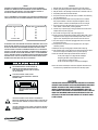
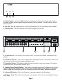
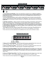
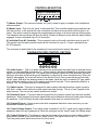
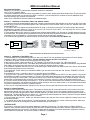
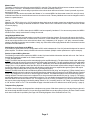
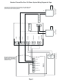
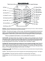
TM MDS-6 OWNERS MANUAL Six-Source Six-Zone Music Distribution Amplifier The MDS-6 is a six source, six zone music distribution amplifier that will fill your home with the highest quality music of any system being built today. It offers unparalleled features in a price range that is very affordable. It features high quality 40 watt RMS Bi-Polar amplifiers per zone, with individual selection and control of each source from each zone. Line outputs off of each zone easily allow additional amplifiers or sub-woofer systems. With the MDS-6 you have independent IR control of all of your audio sources from any room in the house. It also has an integrated interface which allows for whole house paging in conjunction with your phone system, and built-in front and back door chimes. A party mode allows you to select music source and volume for all zones from one location. A built-in IR routing system allows you to operate CD players, satellite receivers, or any other equipment independently even though the same manufacturer makes them and they respond to the same IR codes. Your MDS-6 system may be controlled by the MCS-1, single gang controller, or the MCS-2 dual gang, programmable Controller for complete IR control of your audio equipment from any room of your house. Innovative, rugged and reliable, sleek and unobtrusive, the MDS-6 represents the finest, uncompromising American engineering and design utilizing the highest quality components and manufacturing available, all at a price you can live with. 600-221 rev A DANGER EXPOSURE TO EXTREMELY HIGH NOISE LEVELS MAY CAUSE A PERMANENT HEARING LOSS. INDIVIDUALS VARY CONSIDERABLY TO NOISE INDUCED HEARING LOSS BUT NEARLY EVERYONE WILL LOSE SOME HEARING IF EXPOSED TO SUFFICIENTLY INTENSE NOISE FOR A SUFFICIENT TIME. THE U.S. GOVERNMENT'S OCCUPATIONAL SAFETY AND HEALTH ADMINISTRATION (OSHA) HAS SPECIFIED THE FOLLOWING PERMISSIBLE NOISE LEVEL EXPOSURES: DURATION PER DAY IN HOURS 8 6 4 3 2 1 1/2 HR. or LESS SOUND LEVEL db FLOW RESPONSE 90 93 95 97 100 103 110 ACCORDING TO OSHA, ANY EXPOSURE IN THE ABOVE PERMISSIBLE LIMITS COULD RESULT IN SOME HEARING LOSS. EAR PLUGS OR PROTECTORS IN THE EAR CANAL OR OVER THE EARS MUST BE WORN WHEN OPERATING THIS AMPLIFICATION SYSTEM IN ORDER TO PREVENT A PERMANENT HEARING LOSS. IF EXPOSURE IN EXCESS OF THE LIMITS AS PUT FORTH ABOVE, TO INSURE AGAINST POTENTIALLY HARMFUL EXPOSURE TO HIGH SOUND PRESSURE LEVELS. IT IS RECOMMENDED THAT ALL PERSONS EXPOSED TO EQUIPMENT CAPABLE OF INDUCING HIGH SOUND PRESSURE LEVELS, SUCH AS THIS AMPLIFICATION SYSTEM, BE PROTECTED BY HEARING PROTECTORS WHILE THIS UNIT IS IN OPERATION. THIS APPARATUS SHALL NOT BE EXPOSED TO DRIPPING OR SPLASHING. NO OBJECTS FILLED WITH LIQUIDS SUCH AS VASES SHALL BE PLACED ON THE APPARATUS. IMPORTANT Read all safety and operating instructions before using this product. All safety and operating instructions should be kept for future reference. Obey all cautions in the operating instructions and on the back of the unit. All operating instructions should be followed. This product should not be used near water i.e. bathtub, sink, swimming pool, wet basement, etc. 6. This product should be located so that its position does not interfere with proper ventilation. It should not be placed flat against a wall or placed in a built-in enclosure that will impede the flow of cooling air. 7. This product should not be placed near a source of heat, such as a stove, radiator, or another heat producing amplifier. 8. Connect only to a power supply of the type indicated on the back of the amplifier near the power supply cord. 9. Do not break off the ground pin of the power supply cord. 10. Power supply cords should always handled carefully. Never walk or place equipment on power supply cords. Periodically check cords for cuts or signs of stress, especially at the point where the cord exits the unit. 11. The power supply cord should be unplugged when the unit is unused for long periods of time. 12. If this product is to be mounted in an equipment rack, rear support should be provided. 13. Metal parts and vinyl covering may be cleaned with a damp rag. 14. Care should be taken so that objects do not fall and liquids are not spilled into the unit through the ventilation ports or any other openings. 15.This unit should be checked by a qualified service technician if: A. The power supply cord or plug has been damaged. B. Anything has fallen or been spilled into the unit. C. The unit does not operate correctly. D. The unit has been dropped or the enclosure damaged. 1. 2. 3. 4. 5. 16. The user should not attempt to service this equipment. All service work must be done by a qualified service technician for warranty repairs. TO AVOID ELECTRICAL SHOCK, DO NOT DISASSEMBLE. REFER SERVICING TO QUALIFIED PERSONAL ONLY! CAUTION RISK OF ELECTRIC SHOCK DO NOT OPEN CAUTION: TO REDUCE THE RISK OF ELECTRIC SHOCK, DO NOT REMOVE CHASSIS. NO USER-SERVICEABLE PARTS INSIDE. REFER SERVICING TO QUALIFIED SERVICE PERSONNEL. AVIS: RISQUE DE CHOC ELECTRIQUE-NE PAS OUVRIR. CAUTION THIS AMPLIFIER HAS BEEN DESIGNED AND CONSTRUCTED TO PROVIDE ADEQUATE POWER RESERVE FOR PLAYING MODERN MUSIC WHICH MAY REQUIRE OCCASIONAL PEAK POWER. EXTENDED OPERATION AT ABSOLUTE MAXIMUM POWER IS NOT RECOMMENDED SINCE THIS COULD DAMAGE THE ASSOCIATED LOUDSPEAKER SYSTEM. PLEASE BE AWARE THAT MAXIMUM POWER CAN BE OBTAINED WITH VERY LOW SETTINGS OF THE MASTER VOLUME CONTROLS IF THE INPUT SIGNAL IS VERY STRONG. THIS SYMBOL IS INTENDED TO ALERT THE USER TO THE PRESENCE OF UNINSULATED DANGEROUS VOLTAGE WITHIN THE PRODUCTS ENCLOSURE THAT MAY BE OF SUFFICIENT MAGNITUDE TO CONSITUTE A RISK OF ELECTRIC SHOCK TO PERSONS. THIS SYMBOL IS INTENDED TO ALERT THE USER TO THE PRESENCE OF IMPORTANT OPERATING AND MAINTENANCE (SERVICING) INSTRUCTIONS IN THE LITERATURE ACCOMPANYING THE UNIT. TM Multiplex Technology Inc., 3001 Enterprise St. Brea, CA 92821 Tel. 800-999-5225 Fax 714-996-4900 MDS-6 Music Distribution System TM Power Active On A B C A.) Power Switch - Left on, the MDS-6, when not being used, will go into a sleep mode, ready to turn back on when an input signal is applied from any of the six sources. In the off position, the unit will not function. B.) On LED - With the power switch on, this LED indicates that the unit is powered up and awake. C.) Standby LED - This LED indicates that the unit is plugged into the wall. L ZONE 1 R LINE OUT LEFT RIGHT - + - + 20W/8 OHM X2 LINE OUT / SPEAKER OUT ZONE 2 L R LINE OUT LEFT RIGHT - + - + 20W/8 OHM X2 L ZONE 3 R LINE OUT ZONE 4 L LEFT RIGHT - + - + R LINE OUT 20W/8 OHM X2 ZONE 5 L LEFT RIGHT - + - + R LINE OUT 20W/8 OHM X2 INPUT SOURCES R LEFT RIGHT - + - + 20W/8 OHM X2 ZONE CONTROLLERS L MASTER OUT IN 2 3 OUT D IN OUT SOURCE 2 IN OUT SOURCE 3 IN OUT SOURCE 4 IN OUT IN SOURCE 5 OUT SOURCE 6 8 1 8 1 E 8 1 8 F 1 4 8 1 UNIT ON TRIG ON +5v G +5v G 1 5 6 8 MODEL MDS-6 MULTI-ZONE MADE IN CHINA DESIGNED IN USA 1 8 1 2 3 RISK OF ELECTRIC SHOCK DO NOT OPEN AVIS: RISQUE DE CHOC ELECTRIQUE-NE PAS OUVRIR. WARNING: SHOCK HAZARD - DO NOT OPEN. 4 SOURCE OUTPUT A 1 B G S R IN SOURCE 1 A IR REMOTE OUTPUTS INDIVIDUAL ZONES 1 AUDIO SWITCH INPUT INPUT TM 120V 50/60Hz 300W Multiplex Technology Inc. CAUTION LINE OUT 20W/8 OHM X2 PAGE DOORBELL STATUS ZONE 6 L LEFT RIGHT - + - + B C D SUM OUTPUT 8 G H I D.) Output Section - This section is the output section. It provides the speaker terminals and line outputs. E.) Distribution Section - This section is the line level input/output section. It provides the inputs from your sources and the outputs for stacking additional units. F.) Controller Section - This section is where the wall controller in each zone connect. This section includes the party mode master controller input. G.) Paging/Control Voltage Section - This section is the paging and control voltage input and output section. It provides the inputs from your phone system and door bells (front and back). It also has a control voltage input and output for the unit controlling or being controlled by additional equipment. H.) Infrared (IR) Section - This is the IR section. It provides outputs for the IR emitters. I.) AC Power Cord - This is where the AC power cord connects to the unit. It is a detachable 3 prong I.E.C. plug. Page 1 OUTPUT SECTION ZONE 1 L R LINE OUT 1 LEFT RIGHT - + - + 20W/8 OHM X2 L LINE OUT / SPEAKER OUT ZONE 2 R LINE OUT ZONE 3 L LEFT RIGHT - + - + 20W/8 OHM X2 R LINE OUT LEFT RIGHT - + - + 20W/8 OHM X2 L ZONE 4 R L LEFT RIGHT - + - + LINE OUT ZONE 5 R LINE OUT 20W/8 OHM X2 LEFT RIGHT - + - + 20W/8 OHM X2 L ZONE 6 R LINE OUT LEFT RIGHT - + - + 20W/8 OHM X2 2 1.) Line Outputs (Left & Right) - These are dual RCA line outputs to go to additional amplifiers or to powered sub-woofers. The white one is for left channel and the red one is for right channel. These outputs will react to the volume controllers for each zone. Any changes made to these will follow through to these outputs. If you need additional speakers, say for a deck or large family room and require more power than onboard, simply take these outputs and plug into the larger amp. If you want to run sub-woofers in a zone, you can use powered sub-woofer systems or an additional amp to power them as in the above explanation. 2.) Speaker Connectors - These connectors are where the speaker connections for each zone are made. First determine which individual wire is ground (negative) and the other being the signal (positive) of your speaker wire. The detachable speaker connectors are labeled as L- (left negative); L+ (left positive); R- (right negative); R+ (right positive). There are small set screws on this connector to allow solderless connections to be made. We suggest using a straight blade Jewelers screwdriver to easily make this connection. These speaker outputs are rated at 20 watts RMS a side into an 8 ohm load. Stay within that ohm rating. This will be more than adequate power for most of the in-wall speakers on the market. These connectors are then duplicated for the additional five zones and are identical in nature. DISTRIBUTION SECTION INPUT SOURCES L R IN OUT SOURCE 1 IN OUT SOURCE 2 IN OUT SOURCE 3 IN OUT SOURCE 4 IN OUT SOURCE 5 IN OUT SOURCE 6 3 4 5 6 3.) Source #1 Left Input (White) - This RCA input will accept any standard line level source such as CD, Receiver, Tuner, DSS, TV audio and more. It connects the left channel. 4.) Source #1 Right Input (Red) - This RCA input will accept any standard line level source such as CD, Receiver, Tuner, DSS, TV audio and more. It connects the right channel. 5.) Source #1 Left Output (White) - This RCA output will send a line level signal out, an exact copy of that source signal, from the signal plugged into the left channel of source #1 inputs. It is used for stacking additional MDS-6 units together. This provides an ultra clean audio distribution amplifier for signal clarity. 6.) Source #1 Right Output (Red) - This RCA output will send a line level signal out, an exact copy of that source signal, from the signal plugged into the right channel of source #1 inputs. These connectors are then duplicated for the additional five sources and are identical in nature. Page 2 CONTROLLER SECTION ZONE CONTROLLERS MASTER OUT 1 8 IN 1 8 INDIVIDUAL ZONES 1 1 2 8 1 8 1 4 8 1 5 8 1 6 8 1 8 9 8 7 3 7.) Master Output - This connector allows the party mode to apply to multiple units if additional units are added. 8.) Master Input - This is for the party mode controller. This controller should be located near the unit and sources. It will override all zone controllers and select a source which will then play in all zones. This mode is used for playing the same background music in all zones such as during a party. The individual wall controllers still have the ability to select a different source after the party mode is engaged. It uses a standard 8 pin RJ-45 connector. 9.) Individual Zone #1 Controller - This connector hooks up the wall controllers used in zone #1. The signals from this wall controller control all the functions in zone #1. It uses a standard 8-pin RJ-45 connector. This connector is duplicated for the remaining 5 zones and function exactly the same. PAGING/VOLTAGE CONTROL SECTION PAGE DOORBELL AUDIO SWITCH INPUT INPUT A B STATUS UNIT ON TRIG ON G S S G G S +5v G +5v G 10 11 12 13 14 15 10.) Audio Inputs - This is an audio sensing circuit and accepts the signal from an external phone system, or a pre-amplified microphone (i.e.: a mixer output), that has the capability of sending a page signal from the master phone unit. The signal from this phone system will mute whatever source is playing in all zones and allow the person speaking to page into all zones simultaneously. When the signal is disengaged, the music will return to the previous level. Even zones that are not currently on will open and allow the announcement to be made. Inside the unit is a master DIP type switch which allow the installer to turn off the paging and doorbell override. This is especially suited for a nursery. Pin 1 is for signal and pin 2 is for ground. 11.) Switch Inputs - This input is designed for older systems like intercoms that require a push to talk latch mode contact before the audio signal can pass through. This is a hard bypass of the audio sources. This can act as a whole house mute as well. 12.) Doorbell A Input - This input takes the signal from the contact closers from the front doorbell transformer. When engaged, the source signal mutes and a distinctive chime (on board) plays through the speakers. It will even play through zone speakers that arent on unless locked out. 13.) Doorbell B Input - Same as above but with a separate distinctive chime sound so you can differentiate between the doors. 14.) Control Voltage Output - This output sends a constant 5 volt D.C. signal out to trigger ancillary equipment when the unit is powered up. When the unit goes into the sleep mode, this voltage stops. 15.) Control Voltage In - This allows an external sub system that sends a control voltage output to this system to power up the unit from the sleep mode. This signal can be from 5 to 12 volts D.C. The front panel power switch must be on for this to work. Page 3 INFRARED (IR) SECTION IR REMOTE OUTPUTS 16 SOURCE OUTPUT 17 SUM OUTPUT 1 A 2 B 3 C AVIS: RISQUE DE CHOC ELECTRIQUE-NE PAS OUVRIR. WARNING: SHOCK HAZARD - DO NOT OPEN. 4 D 18 16.) Source Output #1 through 4 - This 1/8 2 conductor jack is for the IR emitters and are locked source specific. This is useful in for instance, if you have 2 or more of the same brand CD player, since the same IR command will work on both, this ONLY sends the IR command to this particular source. Nearly any brand of emitter will work. There are four source specific IR jacks. This connector is duplicated for the remaining 3 outputs and function exactly the same as the first one. 17.) Sum Output #1 through 4 - This 1/8 2 conductor jack is for the IR emitters and are summed across the IR buss. This will allow normal operation of different components that dont share the same IR commands. There are four sum output IR jacks. This connector is duplicated for the remaining 3 outputs and function exactly the same as the first one.. RJ-45 PLUG TO MDS-6 8 7 6 5 4 3 2 1 DATA LINE C DATA LINE B DATA LINE A +5 VOLT D.C. GROUND IR SIGNAL CLONE STANDBY 1 2 3 4 5 6 7 8 RJ-45 PLUG CLIP CLIP 18.) AC Power - This is where the AC power cord connects to the unit. It is a detachable 3 prong I.E.C. plug. Never remove the ground lug on the plug or electrical shock and damage to the unit could result. INSTALLATION NOTES TO MCS-1 or MCS-2 WIRING DIAGRAM FOR REMOTE ROOM CONTROLLERS # Use Category 5 8-conductor cable. It is not necessary for it to be shielded but be careful with your cable runs. Avoid running a tight parallel with AC wiring. Be careful if stapling the wire to secure it in place. # Use high quality RJ-45 connectors and make sure you use a high quality crimp tool. The crimp of the RJ-45 connectors is crucial in making the system work properly. # Avoid tight or sharp turns near the ends of the RJ-45 connections to the controller or main units. This can put excessive strain on already small wires. # Note when stacking multiple units: Audio sources connect via the distribution outputs. Wall controllers combine via the Master Controller Out jack. Make a short jumper and connect to the second units Master Controller In jack to allow the party mode master controller to access all zones. For the IR Emitters, we strongly suggest using a Y adapter for the emitters that attach directly from the sources and then to the second units IR outputs. This allows the source specific functionality to be utilized by the second MDS-6. An additional controller can be run per zone by using a RJ-45 Y adapter before the main unit. Page 4 TM MDS-6 INSTALLATION MANUAL MDS-6 Installation Manual Recommended Cables: Category-5 or Category-3 (4 twisted pair stranded), shielded or unshielded. 16-4 or (2) 16-2 speaker cables. To keep the installation process as simple as possible for first time users, please follow these simple steps. These instructions are written assuming that you are using the MCS-1 controller. If you have the MCS-2 controller, there are additional steps involving teaching the controller IR commands. Please refer to the MDS-6 Reference Manual for additional steps. RJ-45 PLUG 8 7 6 5 4 3 2 1 DATA LINE C DATA LINE B DATA LINE A +5 VOLT D.C. GROUND IR SIGNAL CLONE STANDBY TO MDS-6 1 2 3 4 5 6 7 8 RJ-45 PLUG CLIP CLIP Section 1: Installation of Controller Cables and Speaker Cables. 1. Controllers should be located between wall studs. Locating controllers beside light switches is OK as long as the Cat-5 cable and AC wiring (romex) are not bundled together and in their own box. Each controller cable is home run between each zone and the MDS-6 unit. 2. The ends of the Cat-5 cable are terminated with RJ-45 crimp on connectors (unkeyed). The proper wiring is the same as standard phone company wiring: pin 1 to pin 8, pin 2 to pin 7, pin 3 to pin 6, pin 4 to pin 5,...etc. (see d i a g r a m b e l o w ). Cable testers are available from your local distributor. 3. Each speaker cable is also home run between each speaker and the MDS-6 unit. One pair of 6-8 ohm speakers per zone is recommended. The speaker wires are attached to the 4-pin terminal blocks located in the back of the MDS-6 (these are easily removable for ease of installation). Please observe proper polarity and left-right orientation. 4. All controllers and speakers can then be hooked up to their proper cables but not to the MDS-6 yet. TO MCS-1 or MCS-2 WIRING DIAGRAM FOR REMOTE ROOM CONTROLLERS Section 2: Installation of the MDS-6 unit. 1. Place the MDS-6 in its permanent position in a rack or on a shelf. This unit generates large amounts of heat so please remember to allow for adequate ventilation. The top clearance must be at least 1 inch (25mm). 2. Attach the AC power cord to the unit and plug the cord into the wall. At this point the Power switch should be off. The Standby LED should be on but the On LED should be off. 3. Select which device will be source 1 and attach the audio outputs from it to the audio in terminals on the MDS-6 using standard RCA cables. At this point place this source into play so that you will have audio to monitor. 4. Now attach the speaker connector for zone 1 to the MDS-6 (you decide which room will be which zone, and you should write these assignments down for future reference). 5. Now press the Power button in to activate the MDS-6 (you should now see both the ON and the STANDBY LEDS lit on the MDS-6). 6. Now attach the zone 1 controller to the zone 1 controller input on the MDS-6. 7. Now go to zone 1 controller. If the source 1 equipment is playing you should see two LEDs lit on the controller. The red led that indicates the MDS-6 is powered up and 1 of 6 green LEDs that indicate which source is selected (if the green LEDs are not lit, try pressing the mute button. This button mutes the source audio in this particular zone). Select the proper source by pressing the corresponding button on the left of the controller. Press the volume up button to adjust the listening level. 8. If you do not have sound, please review steps 1-7. If you do have audio please attach the remaining sources to the MDS-6. If all sources are playing, you should now be able to select whichever source you want to listen to. A more detailed description of controller operation is in the MCS-1 operation manual. 9. Once you are comfortable with the operation of one zone you can proceed with wiring the other zones in the same way. Section 3: Infrared Repeater: The MDS-6 has a built-in IR repeater system. This works by sensing any IR commands issued by an IR remote in any zone and passing it through the Cat-5 cable and into the MDS-6 unit. From here it goes to the emitter outputs on the back of the MDS-6. Any IR emitters plugged into the jacks will flash depending on which source is selected and which jack that emitter is plugged into. The jacks labeled Source Outputs 1-4 will flash only when that particular source is selected. The jacks labeled Sum Outputs A-D will flash when any source is selected. 1. Plug an emitter into Source 1 emitter out. Attach the flasher end to the face of the source equipment, making sure to cover the IR sensor window. 2. You should now be able to select Source 1 on the keypad and, using that sources remote, control that source. Make sure you point the remote at the rectangular IR window located at the top of the MCS-1. *SPECIAL NOTE* IR receivers in consumer electronics operate at different modulation frequencies. The most common is 38khz (kilohertz). However, some satellite receivers operate at 56khz and some equipment operates at 32khz. Still other equipment is not even compatible with this type of IR system. The MDS-6 will work with the majority of consumer audio/video equipment. However, some models will not operate. It is up to the installer to determine compatibility. Page 1 Master In/Out: The master controller input will accept a seventh MCS-1 controller. This controller will then become a master control for the entire system. If Source 1 is selected on this controller, all zones will switch to Source 1. If volume up is pressed, all zones will go up and visa versa volume down will lower all zones. If mute is pressed, any zones active will be muted. The Master Out jack can be connected to the Master In on a second MDS-6 to allow master control of 2 units (12 zones). Individual rooms then can override this and return to a local zone mode. This way individual zones can be changed to suit the listener in a particular zone. Unit On: When the On LED is lit, there is a +5v DC applied to these pins that can be used to control any equipment such as relays or digital switches. This voltage is switched off when the Power button is out or the MDS-6 is in the sleep mode such as with no sources playing. Trig On: By applying +5v to +12v DC to these pins, the MDS-6 can be temporarily awakened. If no sources are present, the MDS-6 will return to the sleep mode when the voltage is removed. Using Multiple MDS-6 Units: Up to 3 MDS-6 units may be wired together to provide 18 zones of listening pleasure. First connect all sources into the first MDS-6 and use the Source Outs to connect to the Source Ins on the second unit. Then use the Source Outs on the second unit to connect into the Source Ins on the third unit. Next, using Y-adapters (2-1/8 plugs to 1- 1/8 jack), connect all emitter outputs of the MDS-6 to proper source emitters. Lastly, any connections made to page/doorbell status connectors must also be made to the other MDS-6s. Adding More Audio Power to the MDS-6: If you need more audio power in a zone, simply attach an RCA cable in between the Line Out jacks and the inputs of an external power amplifier. This allows virtually unlimited volumes to be obtained. (Multiple outdoor speakers are a prime example). Section 4: Special Wiring Schemes: The following connections are made to the MDS-6 via the 12 pin terminal block located on the back of the unit. Cat-5 wire or doorbell wire is perfectly suitable for all of these connections. 1. Page/ Doorbell Status: Paging: The MDS-6 has two ways to allow external paging to be amplified through it. The jacks labeled Audio Input will accept any audio signal and will mute the sources and play the page audio automatically. The page sensitivity and level are adjustable via trim pots located inside the MDS-6 (see fig. 1, page 3). Additionally, there are two pins labeled Mute Input. When a DC voltage (+5v to +12v) is applied to these pins the source audio will mute and remain muted until the voltage is dropped. Using an external voltage for the page mute function will still allow an audio page to be amplified through the system and may be advantageous when dealing with a noisy phone line (See diagram page 4). Doorbell: The MDS-6 has two built-in and distinctly different doorbell sounds (ding and ding dong). Either doorbell can be triggered by attaching wires from the houses doorbell transformer (switch side) to the terminals on the MDS-6 labeled Doorbell A or B. Any voltage from 5v to 24v AC or DC will trigger the doorbell. This allows this feature to be used with most types of existing doorbells. Doorbell volume can be adjusted via a trim pot located inside the MDS-6 (see fig. 2, page 3). The paging and doorbell features can be further customized in each zone. You can disable the page/doorbell feature in a zone by setting both slide switches on that zone board to Off. This might be of use in a nursery, for instance. You can set a zone to only mute the sources, but not play the page or doorbell by setting Switch to On, but setting audio to Off. Finally, you could set Switch to Off and set Audio to On. This would allow the page or doorbell audio to mix with the source audio (see fig. 3, page 3). Telephone Entry Systems: The MDS-6 is well suited to be integrated into a telephone entry system. With these systems you can page from any phone in the house through the MDS-6 system. You can also trigger the doorbell or mute the system in some or all zones. Please consult their owners manuals for operation (See Page 4 for the wiring diagrams of the ChannelPlus Door Tel.). Page 2 ( This page is for information only - Consult your Installer for Application ) VR1 502 IR FREQ IR Emitter Modulation Frequency - these are factory set to give optimum preformance of the emitters. Factory setting is 40KHz. Range is 32 KHz full CCW to 65 KHz full CW. IR OUTPUT PC BOARD (Fig. #1) 502 Doorbell Level - adjust to onboard doorbell chime to appropriate level. Factory setting -10db 502 502 DOORBELL/PAGING PC BOARD (Fig. #2) Page Sensitivity - set to match page source output for VOX function. Factory setting -20db. Page Level - adjust to set page level to appropriate level. Factory setting is -10db. Audio - disables doorbell and page audio. Factory setting is on. INDIVIDUAL ZONE PC BOARDS (Fig. #3) Switch - mutes sources when doorbell or page is engaged. Factory setting is on. Set to off if you dont wish to have sources muted when doorbell or page is activated (such as a nursery, etc.). If you want one zone to not be interrupted by paging or the dorrbell, set both switches to off. If you wish to have one zone muted without the doorbell or paging audio set audio switch to off. If you want to leave the source audio in place and have the page and doorbell audio superimposed over the top of it, set switch to off. Page 3 Standard ChannelPlus Door-Tel Phone System Wiring Diagram for Page - 15VDC + POWER SUPPLY THIS SUPPLY IS NOT NEEDED USING ALTERNATE WIRING. - THIS IS ALTERNATIVE WIRING USING EXISTING POWER SUPPLY. POWER SUPPLY + 9VDC-12VDC /100mA When ## is struck audio will go out to the front door only. When #5 is struck audio will go out to the front door and whole house. Intercom between phones and front door works only with ##. + +15VDC - 470 1/2W Door-Tel PAGE OUT SPEAKER OUT DOORBELL STRIKE 1 STRIKE 2 CHIMES DOORBELL BUTTON + + - + - + - Set page sensitivity full counterclockwise, and set page level to desired volume on the MDS-6 amplifier. Refer to page 3 of the installation manual. AUDIO MUTE DOORBELL B UNIT ON TRIGGER ON Page 4 MDS-6 DOORBELL A MCS-1 CONTROLLER MCS-1 1.) IR Receiver 2.) Source Selectors (1 - 6) CD1 POWER 3.) Source LED ( 1 - 6) CD2 MUTE DM1 4.) Power Status LED DM2 VOL 5.) Mute Button AMFM 6.) Volume Up VOL TAPE 7.) Volume Down 1.) IR Sensor - This is an Infrared Sensor window. We suggest you aim the external remote control directly at this window to pass commands back to and through the unit. 2.) Source Selector Buttons (1 - 6) - These buttons will select the source you want to listen to. Individual key caps (supplied with the unit) will allow you to customize the source selections. These can be: CD, Receiver, Tape, DSS, TV or whatever combination you wish. 3.) Source Selection LEDs (1 -6) - These Light Emitting Diodes (LED) will light up next to the selected source to let you know the selection was made. 4.) Power Status LED - This LED indicates the power status of the system. Lighted, the system is on and ready. Off, the system is not engaged. 5.) Mute Button - This button will instantly stop the audio through the system. It is used for temporarily muting the system such as to take a phone call or listen to someone speaking in another room. 6.) Volume Up - This raises the local zone volume up at a rate of 2-4 db per 1/10 second. Hold down the control and the volume goes up quickly. 7.) Volume Down - This lowers the local zone volume down at a rate of 2-4 db per 1/10 second. Hold down the control and the volume goes down quickly. Page 5 MCS-2 CONTROLLER The left side of this controller is identical to the MCS-1 consult last page. MCS-2 8.) Reset 16.) Numeric Entry 17.) Enter Button RESET 9.) Clear 1 2 3 18.) Macro Button 4 5 6 19.) Skip Backward 7 8 9 20.) Skip Forward E 0 M 21.) Power On CLEAR 10.) Clone RX CD1 POWER CD2 11.) Clone TX 12.) Clone/Learn LED MUTE CLONE TX DM1 DM2 VOL CLONE/ LEARN OK ERROR PWR LEARN AMFM 13.) OK LED CLONE RX PLAY VOL IR SENSOR TAPE 22.) Reverse 23.) Forward 24.) Play 25.) Pause 14.) Learn Button 26.) Stop 15.) IR Sensor LED 8.) Reset - This resets the local zone controller if an IR command locks up the zone. It will not erase the local zone memory. It will just send a local clear command. 9.) Clear - This button has 3 modes: a.) Device mode - will clear learned commands from the local zone memory. If you press clear and then say source selector #1 then the commands associated with that page of memory will be erased. b.) Storage mode - this will allow any individual key to be erased and reprogrammed. c.) Macro memory mode - this will allow you to reprogram a individual macro key (0 -9). (This is a permanent erase function, so be careful with this command.) 10.) Clone RX - This button will place the controller into a ready to receive commands mode. This is the learning mode. When setting up the system initially, place all but one controller in this mode and use the one master controller to teach the local zones their commands. The clone/learn LED will light and stay on. When the data is received correctly, the red LED will go out and the green OK light will go on. This process takes between 6 and 8 minutes. *See detailed clone description on page 8. 11.) Clone TX - This button will place the controller into a ready to transmit commands mode. This is the teaching mode. When setting up the system initially, place one controller in this mode and use it as a master controller to teach the other local zones their commands. The clone/learn LED and OK LED will stay on. When the data is transmitted correctly, the red LED will go out and the green OK light will flash then go off. This process takes between 6 and 8 minutes. *See Page 8. 12.) Clone/Learn LED - This LED will let you know the status of transmit and receive during the learning or teaching processes. 13.) OK - This LED will also let you know the progress of the learning/teaching processes. *See Page 8. 14) Learn Button - This button puts the controller into a learning mode.*See Page 8. 15.) IR Sensor - Use this IR window when teaching a controller new IR commands with an external remote. Page 6 MCS-2 CONTROLLER (contd) 16.) Numeric Entry Keys (0 - 9) - Depending on the mode you are in these keys will allow direct track access on a CD, an individual station on TV or DSS, or a station on a tuner, etc. If you are in the macro mode, these will allow direct access to your stored macros. 17.) Enter button - Working in conjunction with the numeric keys above, this button will allow you to address larger numbers quicker. For instance, if you are looking for track # 23 on a CD, you press this 2 and then 3 and enter. This will allow access to DSS and multi-disc changers. The following buttons are completely programmable. They may be reprogrammed to any function you want depending on the source. In fact, they can be any IR related command. It does not even have to pertain to the source units. 18.) Macro Button - This button has its own section. Please refer to the MACRO PROGRAMMING section in this manual. 19.) Skip Backward - This button skips or searches backward. For instance if your source is a CD, it will skip back to the beginning of the track that is playing, then if pushed again, it will skip back to next track previous to the one you are on. Repeat as necessary. This is a programmable button. It may be reprogrammed to any function you want depending on the source. . 20.) Skip Forward - This button skips or searches forward. For instance if your source is a CD, it will skip forward to the beginning of the next track, then if pushed again, it will skip forward to the next track beyond that one. Repeat as necessary. This is a programmable button. It may be reprogrammed to any function you want depending on the source. 21.) Power On - This button will turn on the source power switch from whatever zone you are in. It can be programmed to cycle between on and off. When you program this button, press it once and transmit the code for power on, then press it again for the command to power off. When pressed it will toggle between on and off positions. 22.) Reverse - This button will scan backward within a track if you are in the CD source mode, or move down the dial in a tuner source mode. This is a programmable button. It may be reprogrammed to any function you want depending on the source. . 23.) Forward - This button will scan forward within a track if you are in the CD source mode, or move up the dial in a tuner source mode. This is a programmable button. It may be reprogrammed to any function you want. Pressing and holding it down will move it quicker. This is a programmable button. It may be reprogrammed to any function you want depending on the source. 24.) Play - This button in the CD or tape mode will start playing the appropriate device. This is a programmable button. It may be reprogrammed to any function you want depending on the source. 25.) Pause - Primarily for tape or CD modes, this button will stop the music and wait in the same place until the play button (or other function), is engaged. This is a programmable button. It may be reprogrammed to any function you want depending on the source. . 26.) Stop - This button will stop the CD or tape player in those modes. This is a programmable button. It may be reprogrammed to any function you want depending on the source. Page 7 PROGRAMMING THE MCS-2 CONTROLLERS The MCS-2 controller is designed to learn and store IR codes for virtually any piece of audio/video equipment. This enables the individual programming and use of multiple functions for all of your source components. Programming Individual Functions 1) Press the learn button on the controller. The left, red Clone/Learn LED will begin flashing. 2) Press the source device button to be programmed. 3) Press the numeric or function key you wish to program on the right side of the controller. The red Clone/Learn LED will stop flashing and glow continuously. 4) Hold the source remote control IR emitter 1 to 2 from the IR Sensor on the controller and press the corresponding function key on the source remote. After a short period of time, the right, green OK LED will glow indicating the acceptance of that command. At this point the controller will return to a flashing red LED. It is now ready to be taught the next command for that source. (A solid red and green LED simultaneously indicates an error with that command. Should this occur, clear it and try reentering that function.) 5) Repeat steps 2-4 for the next desired function. 6) When all the desired functions for a particular source have been programmed, we suggest you reset the keypad. 7) Repeat steps 1-6 for the remaining functions. (All of the numeric and function keys will learn any ir code. Functions programmed into the controller are solely at the discretion of the installer.) Cloning The MCS-2 has a cloning feature that will allow you to down load the information stored in one controller to up to five additional controllers within an installation. Once one of the controllers is programmed, go to the other controllers and press the Clone RX button. Then return to the programmed controller and press the Clone/TX button. The green LED will remain lit while the cloning process is in progress. When the process is complete, the green LED will turn off. This should take about 8 minutes. It is a good idea to then reset all of the controllers. Now all the controllers share identical information. The nonvolatile memory will remain regardless of whether the controllers are plugged into the system. Using the Clear button will clear the controller memory. To erase an entire page of memory, simply press the Clear button and then a Source Device button. By pressing a source device button, the Clear button and one of the programmed function buttons will erase a single function. Once cleared, a controller or individual function can be reprogrammed. NOTE: It is important to avoid issuing any IR commands or allowing any external IR interference during the cloning process. This will result in corrupted information being sent to the receiving controllers. Should a controllers programming be corrupted, it may be necessary to completely clear a controller to factory condition. This is done by cloning an unprogrammed controller to the corrupted controller. Once this is done, that controller can then be re-cloned. Page 8 MACRO PROGRAMMING The MCS-2 has 16 programmable macro memories. It will automatically transmit a series of 20 commands deep. To enter the macro mode - press macro and the either the 0 through 9 buttons OR the device source keys (1-6). You can insert a delay time from 1 to 99 seconds between steps (the default is .5 sec.) to suit their specialized needs. To program in time delays, press the appropriate button and hold it from 1 to 99 seconds then input the next command. Here is an example of how to set a macro. The list of things you want to accomplish are: 1.) Power on CD1 2.) Put CD player in disc change mode. 3.) Select disc 10. 4.) Select play mode for CD player. Press Learn then the M button to enter the macro learning mode. The Red LED should begin flashing. Then press the CD1 source device button on the left side of the controller. The following functions will then be grouped as a macro under the CD1 source button. The following selections are made on the right side of the MCS-2 dual controller. See diagram page 7. 1.) Press PWR button 2.) Press the button programmed for disc select 3.) Enter 1 and 0 on the numeric keypad 4.) Press the button programmed for disc enter 5.) Press the button programmed for play Press the learn button or wait 15 seconds for it to return to normal. The red LED should turn off. To utilize the macro mode, press the M button (it will only wait for 2 seconds for a second button to be pressed) then press either numeric button (0-9) or source button (1-6) to engage a pre-programmed macro. To clear a macro out of memory, press the CLEAR then the M buttons and then the key with the memory you wish to erase. It is a permanent erase, so make sure you are careful. If no key is pressed within 15 seconds, the unit will exit the clear mode and return to normal operation. NOTE: All macro commands must come from individual commands already programmed in the MCS-2. They cannot come from the sources wireless remote. Page 9 PROGRAMMING A WIRELESS REMOTE USING THE MCS-1 OR MCS-2 WALL CONTROLLER 1) Remove the Decora cover plate, and controller face plate. 2) Place your wireless remote in learn mode. 3) Select the device bank button to program (i.e. TV, VCR, Tuner, Aux, etc.) on the wireless remote. 4) Select the button to be programmed on the learning remote. (i.e. 1-6, mute, or volume up and down) 5) While holding the wireless remote within 2" from the top, center, clear LED on the MCS-1 (this is the controller IR emitter), press the command button on the MCS-1 Controller you wish to program into the wireless remote. 6) The wireless remote should then accept the MCS-1 command. 7) Once you have programmed the source number, volume up and down, and mute functions. You can then go to the memory bank on your wireless remote chosen for the MDS-6 system to change volume, source, or mute the system from any zone in the house. *Please Note: When programming, it is best to hold the MCS-1 or MCS-2 button until the wireless remote has indicated that it has learned the command. Page 10 Standard Installation Questions for the MDS-6 Can I control volume and source selection with a wireless remote? Yes, the MCS-1 and the MCS-2 controllers have a built-in IR emitter that will teach learning remote the ChannelPlus IR codes for volume, source selection, and mute. How do I control IR if I am using more than one MDS-6 amplifier? The best solution is to use Y cords with two 1/8 male ends going to a 1/8 female end. This works with the 4 source outputs as well as the 4 summed outputs. Can I use more than one controller within a single zone? Yes, the controllers can be tied together via a cat. 5 Y cord or an RJ45-Y adapter. We suggest using only two controllers within one zone. It is also possible to control two zones with one controller. Can I use more than one pair of speakers within a single zone? The MDS-6 is intended to be used with two 8 ohm speakers per zone. It is equipped with line level preamp outs for each zone. You can line out to any external amplifier using standard RCA cables. This makes it possible to power additional speakers, or a powered subwoofer for surround sound systems. Do I have to have all zones playing music to be able to hear the doorbell and page? No, the page and doorbell features will work regardless of the status of the zones. You can, however, use internal switches on each zone to defeat the doorbell and page, or allow the doorbell and page without muting the system. Can I program functions into a macro other than my audio equipment? The MCS-2 controller will learn and store any IR code in its memory. Once an IR command is programmed, that can then be used as part of a series of macro commands. It is important to note that the MCS-2 can only do macros on commands that have already been stored into the controller's memory. Do I need to have a backup for the memory in case of a power outage? No, the MCS-2 controller has a non-volatile memory that will retain its memory once the controller has been programmed. How do I utilize the doorbell and page features? The doorbell and page can be wired with simple two-conductor doorbell wire or standard twisted pair wire such as Cat. 5 or Cat. 3. The doorbell can be lined off of the existing doorbell transformer, or from the doorbell strike on the phone system. Since this feature utilizes a voltage to trigger an internal closure, a 9-volt battery will trigger the doorbell chimes. The page function can be used in two different ways. The simplest method is to take the audio line out from your phone system directly to the audio in on the MDS-6. The MDS-6 is designed to sense the incoming signal and mute the system until a signal is no longer present, at which point it will return to normal operation. It may be necessary to adjust the sensitivity on the page/doorbell board of the MDS-6 to compensate for additional noise in the phone line. An alternative solution to eliminate sensitivity problems between the MDS-6 and the phone system is to add a second power supply (this can be a typical "wall wart") to one of the contact relays on the phone system and from there to the mute input on the MDS-6. This will mute the system regardless of an incoming audio signal, and will remain muted until the phone is hung up. What if none of the lights on the controller come on? It could be that the POWER button is not depressed on the MDS-6. Next verify that you have a source plugged in and playing. Remember that the MDS-6 will go into standby mode after approximately 2 minutes if no incoming signal is detected. If both of these conditions have been met then you probably have an incorrectly wired Cat-5 cable. The correct pin assignment from end to end is: 1 to 8, 2 to 7, 3 to 6, 4 to 5, 5 to 4, 6 to 3, 7 to 2, and 8 to 1. Page 11 What does it mean if the red power LED is lit on the controller, but none of the source LEDs is lit? This condition indicates that the controller is muted. Press the mute button to turn off the mute in that zone at which point one of the source LEDs should light. If this doesnt solve the problem, and you are using the paging and or doorbell hook-ups on the back of the MDS-6, disconnect these. If the page audio inputs are causing the muting then try adjusting the page sensitivity pot in the inside of the MDS-6 (see the owners manual). Sometimes it is necessary to reset the MCS-2 controller by pressing the reset button on the controller. When I am installing the MCS-2 controller, do I have to program each one individually? No. The MCS-2 are equipped with a unique cloning feature. Once you have programmed one controller, you then go to the other controllers in the house and press the Clone RX button. Then go back to the programmed controller and press the clone TX button. The process then occurs automatically, but you need to make sure that you are pressing the clone TX button before the others have timed out, or reverted back to normal operation. In a large house, it may be necessary to do smaller groups of controllers at one time. Future runs of the controllers will have an increased time out of 15 minutes. Once I have programmed my MCS-2 controller, why does some of the source equipment not work? It is possible that the MCS-2 did not store all the commands properly. Try repeating IR commands with the source remote through the IR window of the controller. If the commands pass through the system, then go back to the controller and reenter the desired functions. If the source remote does not work through the systems IR repeater, then you could have a defective emitter. If a different emitter does not solve the problem, then possibly the modulation frequency of the sources IR is well above 40kHz or well below 40kHz. Either scenario is fixable by adjusting the IR frequency trim pot (see the owners manual p.9). I am not using the page or doorbell functions of the MDS-6, but my system has a tendency to mute. The MDS-6 amplifier is equipped with a sensitivity adjustment for the page mute function. It is located on the page /doorbell board inside the unit (see the owners manual p. 9). This trim pot could be set sensitive enough that external noise is triggering the audio sensing circuit. This can be remedied by turning the sensitivity pot completely counter clockwise. An external solution is to place a short wire jumper across the Audio input signal and ground on the 12 pin input located on the back of the unit, thereby disabling the audio sensing circuit of the MDS-6 amplifier. Page 12 INSTALLATION NOTES Date of Purchase: _________ Date of Install: ____________ Serial Number of Unit: __________________________________ Installing Company: ___________________ Name: __________ Installers Address: __________________________________________________ Installers Phone: ___________________________ Source #1: ______________________________________ Source #2: ______________________________________ Source #3: ______________________________________ Source #4: ______________________________________ Source #5: ______________________________________ Source #6: ______________________________________ Additional Notes: Page 13 SPECIFICATIONS Power Output: Frequency Response: T.H.D.: Signal/Noise Ratio: Slew Rate: Input Impedance: Input Sensitivity: Voltage Trigger In: Voltage Trigger Out: Dimensions: Weight: 20 Watts at 8 ohms x 12 20 Hz-20 kHz (+/- 1 dB) 0.2% or less @ rated power >80 dB (A weighted) 10V/u sec. 10k Ohms -10 dBv for rated output 5 volts to 12 volts 5 volts constant 17"W x 3.5"H x 10.5"D 432mm x 90mm x 266mm 14 Lb. (6.4 kg) WARRANTY Multiplex Technology, Inc. / Kustom Sound Systems, Inc. warrants this product to be free of defects in workmanship or materials for a period of three (3) years from the original date of purchase. This warranty applies to the original purchaser only and is not transferable. This warranty is subject to the following conditions and exclusions: -Defects caused by wear and tear, misuse or neglect are not covered by this warranty. -This warranty will be void if: a. The unit has been altered or modified. b. The serial number has been removed or defaced. c. Original purchase is not from an Authorized Kustom Dealer. d. The warranty card is not completely filled out and mailed within 10 days of the original purchase. Neither Multiplex Technology, Inc. or Kustom Sound Systems, Inc., nor authorized Kustom dealers are liable for any incidental or consequential damages resulting from any defect in or failure of Kustom Sound products. This warranty gives the original owner of Kustom Sound products specific legal rights, and he may also have other rights which vary from state to state. This warranty is expressly in lieu of all other agreements and warranties, expressed or implied, except as may be otherwise required by law. For Warranty returns, please contact Multiplex Technology Inc. at 800-999-5225. TM Multiplex Technology, Inc. 3001 Enterprise St. Brea, CA 92821 800-999-5225 fax 714-996-4900 600-221 rev A