1
612547-329
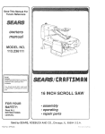
SEARS
OWNERS
MANUAL
MODEL NO.
315.117130
i:i_i
q
CAUTION:
Read Rules for
Safe Operation
and Instructions
Carefully
CRAFTSMAN"
3 INCH
BELT SANDER
DOUBLE INSULATED
SAVE
MANUAL
FUTURE
THIS
Introduction
FOR
Operation
Maintenance
REFERENCE
Repair Parts
Designed exclusively for and sold only by
SEARS, ROEBUCK AND CO., Dept. 698/731A, Sears Tower, Chicago, IL 60684
612547.329
10-86
PRINTED
IN
U,$,A,
FULL ONE YEAR WARRANTY ON CRAFTSMAN
BELT SANDER
If this Craftsman Belt Sander falls to give complete satisfactiori within one year from the date of purchase RETURN IT TO THE NEAREST SEARS STORE THROUGHOUT THE UNITED STATES and Sears
will repair it, free of charge,
If this belt sander is used for commercial or rental purposes this warranty applies for only 90 days from
the date of purchase.
Tills warranty gives you specific legal rights, and you may also have other rights whic_ vary from state
to state.
SEARS, ROEBUCK AND CO.
DEPT. 698/731A
SEARS TOWER
CHICAGO, IL 60684
INTRODUCTION
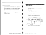
GENERAL
Your Craftsman 3-Inch Belt Sander is suitable for
coarse, medium and fine sanding of wood, metals,
plastics and other materials. It is ideal when used for
smoothing rough boards, chamfering, rounding
edges and many other general sanding applications.
Its balanced design makes it easy to use.
IMPORTANT -- Servicing of a tool with double insulation requires extreme care and knowledge of the
system and should be performed only by a qualified
service technician. For service, return the tool to
your nearest Sears store for repair which will be
done with original factory replacement parts.
DOUBLE INSULATION
Double insulation is a concept in safety, in electric
power tools, which eliminates the need for the usual
three wire grounded power cord and grounded supply system. Wherever there is electric current in the
tool there are two complete sets of insulation to protect the user. All exposed metal parts are isolated
from the internal metal motor components with protecting insulation.
RULES FOR SAFE OPERATION
WARNING -- DO NOT ATTEMPT TO OPERATE THIS TOOL UNTIL YOU HAVE READ THOROUGHLY AND
UNDERSTAND COMPLETELY ALL INSTRUCTIONS, RULES, ETC. CONTAINED IN THIS MANUAL. FAILURE
TO COMPLY CAN RESULT IN ACCIDENTS INVOLVING FIRE, ELECTRIC SHOCK, OR SERIOUS PERSONAL
INJURY. SAVE OWNERS MANUAL AND REVIEW FREQUENTLY FOR CONTINUING SAFE OPERATION, AND
INSTRUCTING POSSIBLE THIRD.PARTY USERS.
READ ALL INSTRUCTIONS
1. KNOW YOUR POWER TOOL -- Read owner's manual carefully.
Learn its applications
and limitations
as well as the specific potential
hazards related to
this
tool.
2. GUARD
WITH
erator
AGAINST
GROUNDED
enclosures.
ELECTRICAL
SURFACES.
SHOCK
For
BY
example:
PREVENTING
BODY CONTACT
Pipes, radiators, ranges, refrig-
3. KEEP GUARDS
IN PLACE and in working
order.
4. KEEP WORK AREA CLEAN.
Cluttered
areas and benches
invite accidents.
5. AVOID
DANGEROUS
ENVIRONMENT.
Don't
use power
tool in damp or wet
locations or expose to rain. Keep work area well lit.
6. KEEP
CHILDREN
AWAY.
All
visitors
should
wear
safety
glasses
and
be kept a safe distance
from work
area. Do not let visitors
contact
tool or
extension
cord.
7. STORE IDLE TOOLS. When not in use, tools should
be stored in a dry, high or
locked-up place -- out of the reach of children.
8. DON'T FORCE TOOL. It will do the job better and safer at the rate for which it
was designed.
9. USE RIGHT TOOL. Don't force small tool or attachment
to do the job of a heavy
duty tool. Don't use tool for purpose
not intended
- for example - Don't use
a circular
saw for cutting
tree limbs or logs.
Page 2
!•
RULES FOR SAFE OPERATION (Continued)
10. WEAR PROPER APPAREL. No loose clothing or jewelry to get caught in moving
parts. Rubber gloves and footwear are recommended when working outdoors.
Also, wear protective hair covering to contain long hair.
11. USE SAFETY GLASSES with all tools. Also face or dust mask if cutting
operation is dusty.
12. DON'T ABUSE CORD. Never carry tool by cord or yank it to disconnect from
receptacle. Keep cord from heat, oil, and sharp edges.
13. SECURE WORK. Use clamps or a vise to hold work. It's safer than using your
hand and it frees both hands to operate tool.
14. DON'T OVERREACH.
Keep proper footing and balance at all times. Do not use
on a ladder or unstable support.
15. MAINTAIN TOOLS WITH CARE. Keep tools sharp at all times, and clean for best
and safest performance. Follow instructions for lubricating and changing accessories.
16. DISCONNECT TOOLS. When not in use, before servicing, or when changing attachments, blades, bits, cutters, etc., all tools should be disconnected.
17. REMOVE ADJUSTING KEYS AND WRENCHES. Form habit of checking to see
that keys and adjusting wrenches are removed from tool before turning it on.
18. AVOID ACCIDENTAL
STARTING. Don't carry plugged-in tools with finger on
switch. Be sure switch is off when plugging in.
19. OUTDOOR USE EXTENSION
CORDS. When tool is used outdoors, use only
extension cords suitable for use outdoors. Outdoor approved cords are marked
with the suffix W-A, for example -- SJTW.A or SJOW-A.
20. NEVER USE THIS OR ANY POWER SANDER FOR WET SANDING. Failure to
comply can result in electrical shock causing serious injury or worse.
21. KEEP HANDS AND FINGERS AWAY FROM SANDING AREA AND MOVING
• SANDING BELT.
22. NEVER USE IN AN EXPLOSIVE ATMOSPHERE.
Normal sparking of the motor
could ignite fumes.
23. INSPECT TOOL CORDS PERIODICALLY
and if damaged, have repaired at your
nearest Sears Repair Center. Stay constantly aware of cord location.
24. INSPECT EXTENSION CORDS PERIODICALLY
and replace if damaged.
25. KEEP HANDLES DRY, CLEAN, AND FREE FROM OIL AND GREASE. Always
use a clean cloth when cleaning. Never use brake fluids, gasoline, petroleumbased products, or any strong solvents to clean your tool.
26. STAY ALERT. Watch what you are doing and use common sense. Do not operate tool when you are tired. Do not rush.
27. CHECK
DAMAGED
PARTS. Before
further
use of the tool, a guard or
other part that is damaged should be carefully checked to determine that it will
operate properly and perform its intended function. Check for alignment of moving parts, binding of moving parts, breakage of parts, mounting,
and any other
conditions
that may affect its operation. A guard or other part that is damaged
should be properly repaired or replaced by an authorized
service center unless
indicated elsewhere
in this instruction
manual.
28. DO NOT USE TOOL IF SWITCH DOES NOT TURN IT ON AND OFF. Have defective switches replaced by authorized
service center.
29. Inspect for and remove all nails from lumber before sanding.
30. DRUGS, ALCOHOL, MEDICATION.
Do not operate tool while under the influence of drugs, alcohol, or any medication.
31. SAVE THESE INSTRUCTIONS.
Refer to them frequently
and use them to
instruct third party users. If you loan someone your Sander, loan them these
instructions
also.
Page 3
OPERATION
J
J
i
Jl-
.....
i
REAR
TRACKING
SCREW
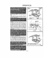
Make sure power supply is 110-120 volts, 60 HZ, AC
only.
HANDLE
Before attempting to u_e your Sander, familiarize
yourself with al{ operating features (See Figure 1)
and safety requirements,
FRONT IDLER
PULLEY
i
, iHi
i
i
SANDING
BELT
i
i,l,i
Fig
iim,iH
1
-,
LOCK "ON"
BUTTON
SWITCH
The switch
of your sander is equipped
with a "lockon" feature
which is convenient
when sanding
for
extended
periods of time, To lock-on, simply depress
the trigger
of the switch,
push in the lock button
lQ_c_t__d
_ont.he_si__e
_ofthe ha_nd_!e,
thenwhi!_eh_o!_ding
the look button
pushed
in, release the trigger
See
Pigure 2 To release ihe lock, depress the trlgger and
release it I1 you have the "Lock-On"
feature engaged
during
use and your Sander becomes
disconnected
from power suppty, disengage
the "Lock-On"
feature
immediate!,
CORRECT
i
PREPARING
i
,iii,H
.......
Fig. 2
i
II
III
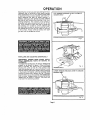
FOR OPERATION
For e_ge of operation and maintaining proper con,
trol, your Sander has a front handte and a rear handle These handles allow two-hand
operation
which
aid in maintaining
control,
keeping
sanding
area
_evet with workpiece,
and keeping
hands clear ot
sandincj
belt. When operating
your Sander always
hold the front handle with your left hand and the rear
handle with your right hand as shown in Fig. 2.
iSee
Fig
3
KEEP HANDS AND FINGERS
AWAY FROM THESE AREAS AT ALL TIMES
FtO. 3
Aiways
operate
your
Sander
as shown
in Fig
2.
Page 4
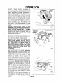
OPERATION
Selecting the correct size and type sanding belt Is an
important step tn achieving a high quality sanded
finish. Standard 3 inch x 21 inch sanding belts made
of alumi'num oxtde, silicone carbide, and othel' synthettc abrasives are best for power sanding. In
general, coarse grit will remove the most material
LIFT TENSION RELEASE LEVER TO REMOVE
SANDING BELT
and fine grit wil! produce the gm0oth_t flni_h in Wl
sanding operations. The condition of the surface to
be sanded wi!l determine which grit belt will do the
job, If the surface is rough, start with a coarse grit
belt sanding until surface is uniform Medium grit
belt may then be used to remove scratches left by
the coarser belt and fine grit belt used for finishing
of the surface. Always continue sanding with each
grit belt until the surfao_ i_ uniform
Fig. 4
INSTALLING
AND ADJUSTING SANDING BELT
DISCONNECT
SANDER FROM POWER SUPPLY
WHILE ASSEM_BL_!NG pA_RT_SOR MAKING ADJUSTMENTS.
To release the sanding belt, lift tenston release lever
straight up as shown in figure 4. When sufficient
force is exerted, the spring will be compressed
attowtng the pulley to lock in a rear position This
frees the sanding belt so It can be removed. Install
new belt making sure arrow inside of belt ls pointing
in the direcUoh b{ rOt_tion, whieh is eloekwi_e when
looking into open side of sander, See Fig 5, Reughly
align the belt to its correct poWtiort, then releage tension on pulley. Retease tension by lowering tension
release lever as shown in Figure 6 The pulley will
snap back into operating position
,____"'":"1"
, _;',.
_,.....-._
::_.:_:';__
...._
Fig 5
SANDING BELT
....
LOWER TENSION RELEASE LEVER TO SECURE
sANDiN(_ BELT
Fig 6
i
Page 5
H
i
OPERATION
ALWAYS
WEAR
SAFETY
GLASSES
OR
EYESHIELDS WHEN OPERATING YOUR SANDER.
4
ii!i:
To adjust sanding belt, connect Sander to power
supply. Place Sander in upside down position as
shown in Figure 7. NOTE: This position is for adjustments only. The Sander is not in an operating
position. Pull switch trigger and release immediately, Observe tracking of sanding belt. If the sanding
belt runs inward, turn the tracking screw clockwise.
If the sanding belt runs outward, turn the tracking
screw counterclockwise.
This should be done until
you are sure belt will not run off sander, or come in
contact with internal parts. After installing a new
sanding belt, it may become necessary to change
the adjustment several times until the belt becomes
pliable.
WARNING: IF SANDING BELT BEGINS TO WEAR
EXCESSIVELY ON THE INNER EDGE, RE-ADJUST
TRACKING SCREW. IT IS ADJUSTED TOO FAR IN.
WARD AND THE SANDING BELT IS RUBBING
AGAINST INTERNAL PARTS. When you are sure the
belt will not rub against internal parts, start your
Sander and fine adjust the tracking screw until the
belt stabilizes. See Figure 8,
SANDING
BELT
TRACKING
SCREW
When correctly adjusted, the outer edge of the belt
will be even with the outer edge of the base of your
Sander. Belt life will be greatly increased if a few seconds are spent adjusting the belt tracking.
WARNING: KEEP HANDS AND FINGERS AWAY
FROM MOVING SANDING BELT. ANY PART OF
YOUR BODY COMING IN CONTACT WITH MOVING
BELT COULD RESULT IN SERIOUS INJURY. DO
NOT WEAR LOOSE CLOTHING OR JEWELRY
WHEN OPERATING YOUR SANDER. THEY COULD
GET CAUGHT IN MOVING PARTS AND FOREIGN
OBJECTS COULD GET THROWN AWAY FROM
SANDER CAUSING INJURY.
TO OPERATE
Clamp or otherwise secure the work to prevent it
from moving
under your Sander. WARNING:
UNSECURED WORK COULD BE THROWN BACK
TOWARD OPERATOR CAUSING INJURY. Before
placing Sander on work surface, squeeze the trigger
switch and let the motor reach its maximum speed,
then lower your Sander to the work surface with a
slight forward motion. Using the rear handle to control your Sander and the front handle only to guide it,
move it slowly over the work, See Fig. 9. Allowing
your Sander to remain in one place will result in an
uneven surface, WARNING: KEEP A FIRM GRIP ON
SANDER WITH BOTH HANDS AT ALL TIMES.
FAILURE TO DO SO COULD RESULT IN LOSS OF
CONTROL LEADING TO POSSIBLE SERIOUS INJURY. Your Sander was designed to provide the proper weight on the sanding belt. Extra pressure will
result in uneven work, clogged belts, and possible
motor burnout. NOTE: The front roller of your sander
was not designed for contour sanding. Sanding on
the front roller could cause irregularity in sanding
belt tracking.
Use a coarse belt when heavy cutting is desired, not
heavy pressure, The importance of this cannot be
over-emphasized. The weight has been built into the
tool to give the most efficient pressure at the proper
location.
Page 6
Fig. 8
Fig. 9
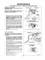
MAINTENANCE
WHEN
SERVICING
USE ONLY IDENTICAL
REPLACEMENT
PARTS.
TIMING BELT REPLACEMENT
DISCONNECT SANDER
BEFORE SERVICING
FROM
POWER SUPPLY
WHEN REPLACING TIMING BELT, USE REPLACEMENT BELT NUMBER 989368-000 ONLY. See Key
Number 5 on Parts List, Page 11.
1.
2.
3.
4.
5.
6.
S _EMALL
PULLEY
Remove sanding belt from sander. See installing
and adjusting
sanding belt, Page 5. NOTE:
REMOVING
THE SANDING
BELT WILL
SIMPLIFY THE PROCESS OF INSTALLING
YOUR NEW TIMING BELT.
Remove the two belt cover screws. Then remove
the belt cover. See Key Numbers 1 and 2 on exploded view and/or parts list, pages 10 and 11.
Force old belt from small pulley with
a
screwdriver and remove it from large pulley. If it
is worn out, simply cut the old belt and remove it.
Install new belt over large pulley first. See Figure
10.
Holding the belt as shown in Figure 11, press the
belt onto the small pulley. NOTE: TO SIMPLIFY
THE PROCESS, TURN THE LARGE PULLEY AS
YOU PRESS THE BELT ONTO THE SMALL
PULLEY.
Reassemble belt cover and screws.
TIMING BELT
.=_
BELT COVER
BELT COVER
SCREWS
PULLEY
Fig. 10
APPLY PRESSURE
HERE AND TURN LARGE PULLEY
Fig. 11
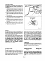
SWITCH REPLACEMENT
DISCONNECT THE SANDER FROM POWER SUPP.
LY WHILE REPLACING PARTS OR MAKING ADJUSTMENTS.
.
.
,
,
.
6.
Remove the handle cover and screws. NOTE THE
LOCATIONS OF ALL WIRING IN THE HANDLE
AND HOW EACH CONNECTION IS MADE TO
THE SWITCH. Connections and wiring position
must be identical when installing the new
switch. See Figure 12.
Lift the switch away from the handle, then
release the leads to the switch by inserting a
1/32" diameter pin or nail into each switch lead
receptacle. See Figure 13.
HANDLE COVER
Fig. 12
1/32" DIAMETER
NAIL OR PIN
Make the lead connections to the new switch by
pushing each lead as far as possible into the
switch lead receptacles. Pull on leads to check
lead connections with lead receptacles.
Arrange the wiring in the handle so that it will not
be pinched when the handle cover and screws
are replaced, then position theswitch
in place.
See Figure 12.
Place the cord and bend relief
locations. See Figure 12.
in their correct
Replace handle cover and screws.
Fig. 13
7. Tighten all screws securely.
Page 7
CORD REPLACEMENT
DISCONNECT THE SANDER FROM POWER SUPP.
LY WHILE REPLACING PARTS OR MAKING AD.
JUSTMENTS.
1. Remove handle cover and screws as described
on Page 7. Note the locations of all wiring in the
handle and how each connection is made to the
cord. Connections and wiring position must be
identical when installing
the new cord. See
Figure 14.
2. Remove the switch from the handle and disconnect the cord leads from the switch. See Figure
15.
3. Remove the bend relief from old cord and place it
on the new one.
4. Push each lead of the new cord as far as possible
into the proper switch lead receptacles. Pull on
leads to check lead connections with lead receptacles.
5. Arrange the wiring in the handle so that it will not
be pinched when handle cover and screws are
replaced. Position the switch in place. See
Figure 14.
6. Place the bend relief and cord in their correct
locations, then replace handle cover and screws.
7. Tighten all screws securely.
BEND
HANDLE COVER
Fig. 14
1/32" DIAMETER
NAIL OR PIN
Fig. 15
ii.
i, +.
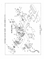
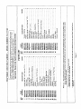
GENERAL
Only the parts shown on parts list, page eleven, are
intended to be repaired or replaced by the customer.
All other parts represent an important part of the
double insulation system and should be serviced only by a qualified service technician.
Avoid using solvents when cleaning plastic parts.
Most plastics are susceptible to various types of
commercial solvents and may be damaged by their
use. Use clean cloths to remove dirt, carbon dust,
etc. WARNING: DO NOT AT ANY TIME LET BRAKE
FLUIDS, GASOLINE, PETROLEUM-BASED
PRO.
DUCTS, PENETRATING OILS, ETC. COME IN CON.
TACT WITH PLASTIC PARTS. THEY CONTAIN
CHEMICALS
THAT CAN DAMAGE, WEAKEN,
AND/OR DESTROY PLASTIC.
EXTENSION CORDS
The use of any extension cord will cause some loss
of power. To keep the loss to a minimum and to prevent tool overheating, follow the recommended cord
sizes on the chart at right. When tool is used outdoors, use only extension cords suitable for outdoor
use and so marked. Extension cords are available at
Sears Catalog Order or Retail Stores.
When electric tools are used on fiberglass boats,
sports cars, etc., it has been found that they are subject to accelerated wear and possible premature
failure, as the fiberglass chips and grindings are
highly abrasive to bearings, brushes, commutator,
etc. Consequently it is not recommended that this
tool be used for extended work on any fiberglass
material. During any use on fiberglass it is extremely
important that the tool is cleaned frequently by blowing with an air jet. ALWAYS WEAR SAFETY
GLASSES OR EYE SHIELDS BEFORE BEGINNING
POWER TOOL OPERATION OR BLOWING DUST.
LUBRICATION
All the bearings in this toot are lubricated with a sufficient amount of high grade lubricant for the life of
the unit under normal
operating
conditions,
therefore, no further lubrication is required.
Extension Cord Length
25-50 Ft.
50-100 Ft.
Wire Size A.W.G.
16
14
WARNING: CHECK EXTENSION CORDS BEFORE
EACH USE. IF DAMAGED, REPLACE IMMEDIATELY.
NEVER USE TOOL WITH A DAMAGED CORD SINCE
TOUCHING THE DAMAGED AREA COULD CAUSE
ELECTRICAL SHOCK RESULTING IN SERIOUS INJURY.
Page 8
THE FOLLOWING RECOMMENDED ACCESSORIES ARE CURRENT AND
WERE AVAILABLE AT THE TIME THIS MANUAL WAS PRINTED.
CORD LOCK
Cat. No. 9 2595
CARRYING CASE
Cat. No. 9 14703
CRAFTSMAN
CLOTH BACKED SANDING BELTS
Cat. No. 9 22304-X-Fine
Cat. No, 9 22301-Fine
Cat. No. 9 22302.Medium
Cat. No, 9 22303-Coarse
Cat, No. 9 22305.X.Coarse
POLYESTER BACKED SANDING BELTS
Cat. No. 9 23201.X-Fine
Cat. No. 9 23202.Fine
Cat. No. 9 23203-Medium
Cat. No. 9 23204-Coarse
Dustless Sanding Attachment 9 11766
CAUTION: The use of attachments or accessories not listed above might be hazardous,
NOTES
L ,
Page 9
0
0
c_
Q..
/
m
Z
L_
LL
/
0
\
\
/
\
\
\
O
..........
°
....
..........
..........
..........
•
°
°
....
,
....
,
....
,
,
•
.
.
,
°
,
,
.........
,
•
,
°
....
• I1
Z
"1-
......
13.
'.--_ '
_'_
I--
a
,
T
" _
_
O
....
X
('0
'iT
''_
.....
"_"_
.....
.....
,
,
•
°
,
,
al m
-_
E
:_
_.
.....
:
: : : : :
•
_
O0
•
¢0
'_-
_
.....
•
•
•
$
o
.
w
o
o
._
.E .E -- 6-
.5
OF-O-
,,=,
o_._'=..-.o
oO m (,9 ._
0
o
,-0
o
_- ...
oo,_o'_- (Dt--
coco
mOT
o
l_,,em
•
o
t-- .I::: o
-=_ _
_)
o_
o o
I..-
._-
O
L.U
thr_J
t-
O---
.=
8
"O
O
O-Q
E
_Eg
O
o"o
_
_z
O
&
,,=,
8
O-1
_ f- -g
I
h
E
o
E
"O
r-
ot,t •
"--_-
Q
O
2_ z
r"
m
m
__
"-=
8
._EiEmU-
co
8
Z
W
p14.
r- _._
k- if) "_
w
nO
i°
•"_ _
I--
o
_=<___
Z
_Z
.................
_
____
O
i
"
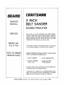
CRRFTSMRN
SEARS
3 INCH
BELT SANDER
OWNERS
MANUAL
DOUBLE INSULATED
SERVICE
MODEL
Now that you have purchased
your Belt Sander,
should a need ever exist for repair parts or service,
simply contact any Sears Service Center and most
Sears, Roebuck and Co. stores. Be sure to provide
all pertinent
facts when you call or visit.
NO.
315.117130
The model number of your Belt Sander will be found
on the plate located on the side of your sander,
HOW TO ORDER
REPAIR
WHEN ORDERING
REPAIR PARTS, ALWAYS
THE FOLLOWING
INFORMATION'
PARTS
•
PART
NUMBER
•
MODEL
" PART
NUMBER
•
GIVE
DESCRIPTION
NAME OF ITEM
3" Belt Sander
315.117130
All parts listed may be ordered from any Sears Service Center and most Sears stores.
If the
order
Repair
SEARS,
ROEBUCK
AND
parts you need are
will be electronically
Parts
Distribution
CO., Dept. 698/731A,
Sears
not stocked
transmitted
Center
Tower,
locally,
your
to a Sears
for handling.
Chicago,
IL 60684