1
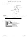
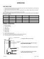
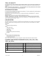
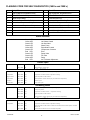
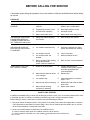
Owner / Operator Manual
Commercial Refrigeration Service, Inc.
WWW.IceCubes.NET
(866) 423-6253
IMPORTANT:
TO THE INSTALLER.
It is the responsibility of
the Installer to ensure that
the water supply to the
dispensing equipment is
provided with protection
against backflow by an air
gap as defined in
ANSI/ASME A112.1.2-1979;
or an approved vacuum
breaker or other such
method as proved effective
by test.
Water pipe connections
and fixtures directly
connected to a potable
water supply shall be
sized, installed, and
maintained according to
Federal, State, and Local
Codes.
THIS DOCUMENT CONTAINS IMPORTANT INFORMATION
This Manual must be read and understood before installing or
operating this equipment
Release Date: December 7, 2001
Revision Date: March 18, 2002
Publication Number: 630460146
Revision: F
www.cornelius.com
IMI Cornelius Inc.
Corporate Headquarters
One Cornelius Place
Anoka, MN 55303–6234
U.S.A.
Distributed By:
Commercial Refrigeration Service, Inc.
WWW.Cornelius Parts.COM
WWW.IceCubes.NET
(866) 423-6253
(623) 869-8881
Model and Serial Location . . . . . . . . . . . . . . . . . . . . . . . . . . . . . . . . .
1
Xtreme Ice Machine . . . . . . . . . . . . . . . . . . . . . . . . . . . . . . . . . . . . . . . . . . . . . . . .
Serial Number Explanation . . . . . . . . . . . . . . . . . . . . . . . . . . . . . . . . . . . . . . . . . .
Specifications . . . . . . . . . . . . . . . . . . . . . . . . . . . . . . . . . . . . . . . . . . . . . . . . . . . . . .
1
1
2
General . . . . . . . . . . . . . . . . . . . . . . . . . . . . . . . . . . . . . . . . . . . . . . . . . . .
4
Freight Damage Claims Procedure . . . . . . . . . . . . . . . . . . . . . . . . . . . . . . . . . . .
Technical Specifications . . . . . . . . . . . . . . . . . . . . . . . . . . . . . . . . . . . . . . . . . . . . .
4
4
Installation Instructions . . . . . . . . . . . . . . . . . . . . . . . . . . . . . . . . . . .
5
Location of Equipment . . . . . . . . . . . . . . . . . . . . . . . . . . . . . . . . . . . . . . . . . . . . . .
Equipment Set-Up . . . . . . . . . . . . . . . . . . . . . . . . . . . . . . . . . . . . . . . . . . . . . . . . . .
Dispenser Installation . . . . . . . . . . . . . . . . . . . . . . . . . . . . . . . . . . . . . . . . . . . . . . .
Plumbing Connections . . . . . . . . . . . . . . . . . . . . . . . . . . . . . . . . . . . . . . . . . . . . . .
Electrical . . . . . . . . . . . . . . . . . . . . . . . . . . . . . . . . . . . . . . . . . . . . . . . . . . . . . . . . . .
Installation Check Points . . . . . . . . . . . . . . . . . . . . . . . . . . . . . . . . . . . . . . . . . . . .
Start Up Sequence . . . . . . . . . . . . . . . . . . . . . . . . . . . . . . . . . . . . . . . . . . . . . . . . .
Preventative Maintenance Sequence . . . . . . . . . . . . . . . . . . . . . . . . . . . . . . . . . .
5
5
6
6
7
7
7
7
Operation . . . . . . . . . . . . . . . . . . . . . . . . . . . . . . . . . . . . . . . . . . . . . . . .
8
Unit Selection . . . . . . . . . . . . . . . . . . . . . . . . . . . . . . . . . . . . . . . . . . . . . . . . . . . . . .
Normal Operations . . . . . . . . . . . . . . . . . . . . . . . . . . . . . . . . . . . . . . . . . . . . . . . . .
Start Up Sequence (Primary) . . . . . . . . . . . . . . . . . . . . . . . . . . . . . . . . . . . . . . . .
Secondary Start Up . . . . . . . . . . . . . . . . . . . . . . . . . . . . . . . . . . . . . . . . . . . . . . . . .
Dump Cycle . . . . . . . . . . . . . . . . . . . . . . . . . . . . . . . . . . . . . . . . . . . . . . . . . . . . . . .
Water Fill Cycle . . . . . . . . . . . . . . . . . . . . . . . . . . . . . . . . . . . . . . . . . . . . . . . . . . . .
Pre Chill Cycle (300’s, 500’s, 600’s, 800’s, 1000’s, and 1200’s) . . . . . . . . . . .
Pre Chill Cycle (1400’s and 1800’s) . . . . . . . . . . . . . . . . . . . . . . . . . . . . . . . . . . .
Freeze Cycle . . . . . . . . . . . . . . . . . . . . . . . . . . . . . . . . . . . . . . . . . . . . . . . . . . . . . .
Harvest Cycle . . . . . . . . . . . . . . . . . . . . . . . . . . . . . . . . . . . . . . . . . . . . . . . . . . . . . .
Dump Cycle . . . . . . . . . . . . . . . . . . . . . . . . . . . . . . . . . . . . . . . . . . . . . . . . . . . . . . .
Fan Control . . . . . . . . . . . . . . . . . . . . . . . . . . . . . . . . . . . . . . . . . . . . . . . . . . . . . . . .
Calibration Mode . . . . . . . . . . . . . . . . . . . . . . . . . . . . . . . . . . . . . . . . . . . . . . . . . . .
Adjusting Bridge Thickness . . . . . . . . . . . . . . . . . . . . . . . . . . . . . . . . . . . . . . . . . .
Total Ice Capacity . . . . . . . . . . . . . . . . . . . . . . . . . . . . . . . . . . . . . . . . . . . . . . . . . .
Ice Production Check . . . . . . . . . . . . . . . . . . . . . . . . . . . . . . . . . . . . . . . . . . . . . . .
LED Indicators . . . . . . . . . . . . . . . . . . . . . . . . . . . . . . . . . . . . . . . . . . . . . . . . . . . . .
Flashing Code for Self Diagnostics . . . . . . . . . . . . . . . . . . . . . . . . . . . . . . . . . . . .
Harvest Button . . . . . . . . . . . . . . . . . . . . . . . . . . . . . . . . . . . . . . . . . . . . . . . . . . . . .
Manual Harvest . . . . . . . . . . . . . . . . . . . . . . . . . . . . . . . . . . . . . . . . . . . . . . . . . . . .
Unit Check . . . . . . . . . . . . . . . . . . . . . . . . . . . . . . . . . . . . . . . . . . . . . . . . . . . . . . . .
Clean Button . . . . . . . . . . . . . . . . . . . . . . . . . . . . . . . . . . . . . . . . . . . . . . . . . . . . . . .
Clean Cycle . . . . . . . . . . . . . . . . . . . . . . . . . . . . . . . . . . . . . . . . . . . . . . . . . . . . . . .
8
8
9
9
9
9
9
9
10
10
10
10
10
10
11
11
11
11
13
13
13
13
13
Maintenance . . . . . . . . . . . . . . . . . . . . . . . . . . . . . . . . . . . . . . . . . . . . . .
14
General Ice Machine Inspection . . . . . . . . . . . . . . . . . . . . . . . . . . . . . . . . . . . . . .
Cleaning the Exterior . . . . . . . . . . . . . . . . . . . . . . . . . . . . . . . . . . . . . . . . . . . . . . .
Cleaning the Condenser . . . . . . . . . . . . . . . . . . . . . . . . . . . . . . . . . . . . . . . . . . . . .
Air–Cooled Condenser . . . . . . . . . . . . . . . . . . . . . . . . . . . . . . . . . . . . . . . . . . . . . .
Water-Cooled Condenser (and regulating valve) . . . . . . . . . . . . . . . . . . . . . . . .
14
14
14
14
15
Cleaning the Interior . . . . . . . . . . . . . . . . . . . . . . . . . . . . . . . . . . . . . . . . . . . . . . . .
Cleaning Procedure if there is Ice on the Evaporator Plate. . . . . . . . . . . . . . . .
Cleaning the Water System and Evaporator . . . . . . . . . . . . . . . . . . . . . . . . . . . .
Sanitizing the Water System and the Evaporator . . . . . . . . . . . . . . . . . . . . . . . .
15
15
15
16
Before Calling for Service . . . . . . . . . . . . . . . . . . . . . . . . . . . . . . . . .
18
Warranty . . . . . . . . . . . . . . . . . . . . . . . . . . . . . . . . . . . . . . . . . . . . . . . . .
19
IMI Cornelius Offices . . . . . . . . . . . . . . . . . . . . . . . . . . . . . . . . . . . . . . . . . . . . . . . .
19
MODEL AND SERIAL LOCATION
XTREME ICE MACHINE
Condenser Discharge Air
Deflector (as required)*
Bin Adapter (as required)*
Model/Serial
Number Location
FIG. 1
*Bin adapters and condenser discharge air deflector may be equipped depending on your location or the size of
the storage bin.
Record the model number and the serial number of your ice equipment. These numbers are required when requesting information from your local dealer/distributor/service company.
Model Number –
Serial Number –
Date Installed –
Purchased From -
SERIAL NUMBER EXPLANATION
63 A 01 01 BC 101
Sequential Number
Product Code (PC) – Ice Maker
Week of Manufacture – First week of the year
Year of Manufacture – 2001
Control Code (Revision Level)
Manufacturing Location – Mason City
March 18, 2002
1
630460146
SPECIFICATIONS
The following table contains equipment specification information for the Ice Machines.
XAC
XWC
XAC
XWC
XRC
Model 322/330 322/330 522/530 522/530 522/530
XAC
630
XWC
630
XRC
630
XAC
830
UNIT
Volts
Phase
Hertz
No. Wires
115
1
60
2+Ground
230
1
60
2+Ground
MIN. CIRCUIT
Amps
20
15
20
20
15
20
MAX. FUSE
SIZE
Amps
REFRIGERANT
Type
Weight (oz)
Weight (g)
R404a
19
539
R404a
15
426
R404a
25
709
R404a
135
3,827
R404a
23
652
R404a
40
1,134
R404a
35
992
R404a
170
4,820
R404a
42
1,191
COMPRESSOR
LRA
RLA
58.8
9.2
68
11.9
40.6
6.9
60
8.9
CONDENSER
FAN MOTOR
Amps
Watts
1.7
50
NA
NA
1.7
50
NA
NA
NA
NA
1.1
75
NA
NA
NA
NA
XWC
1030
0.7
20
XRC
1030
XAC
1230
XWC
1230
XRC
1230
R404a
49
1,191
R404a
45
1,276
R404a
210
5,954
1.1
75
WATER PUMP
Amps
Watts
Model
XWC
830
XRC
830
XAC
1030
UNIT
Volts
Phase
Hertz
No. Wires
230
1
60
2+Ground
MIN. CIRCUIT
Amps
20
MAX. FUSE
SIZE
Amps
20
REFRIGERANT
Type
Weight (oz)
Weight (g)
R404a
33
936
R404a
170
4,820
R404a
42
1,191
R404a
33
936
R404a
170
4,820
COMPRESSOR
LRA
RLA
60
8.9
90
12
96
13.5
84
12.2
CONDENSER
FAN MOTOR
Amps
Watts
NA
NA
NA
NA
1.2 (2)
60 (2)
NA
NA
NA
NA
1.2 (2)
60 (2)
NA
NA
NA
NA
WATER PUMP
Amps
Watts
630460146
0.7
20
2
March 18, 2002
Model
XAC
1444
XWC
1444
XRC
1444
XAC
1844
XWC
1844
XRC
1844
XAC
322
E50
XAC 330
E50
XAC 522
E50
XAC 530
E50
UNIT
Volts
Phase
Hertz
No. Wires
230
1
60
2+Ground
220
1
50
2+Ground
MIN. CIRCUIT
Amps
30
40
20
30
40
20
MAX. FUSE
SIZE
Amps
REFRIGERANT
Type
Weight (oz)
Weight (g)
R404
a
36
1021
R404
a
67
1900
R404
a
R404
a
250
7088
R404
a
R404
a
R404
a
19
539
R404a
19
539
R404a
25
709
R404a
25
709
COMPRESSOR
LRA
RLA
108
17
CONDENSER
FAN MOTOR
Amps
Watts
0.6
1/15
HP
NA
NA
179
28
NA
NA
26.3
3.9
31
5.6
NA
NA
NA
NA
1.75
50
1.75
50
1.75
50
1.75
50
XAC
1844
3PH
0.7
20
XWC
1844
3PH
XRC
1844
3PH
XWC
522/530
E60
XWC
522
E50
XAC
522/530
E60
2.7
1/3HP
WATER PUMP
Amps
Watts
Model
XAC
630
E50
XAC
830
E50
XAC
1030
E50
XAC
1230
E50
UNIT
Volts
Phase
Hertz
No. Wires
220
1
50
2+Ground
230
3
60
3+Ground
230
220
230
1
1
1
60
50
60
2+Ground 2+Ground 2+Ground
MIN. CIRCUIT
Amps
15
20
20
20
15
15
20
20
20
15
R404a
23
652
R404a
26
737
MAX. FUSE
SIZE
Amps
REFRIGERANT
Type
Weight (oz)
Weight (g)
R404a R404a R404a R404a R404a R404a R404a
40
1134
42
1191
42
1191
49
1389
34
5.5
54
8.1
83
11.3
76
13
1.1
75
1.1
75
1.2(2)
60(2)
COMPRESSOR
LRA
RLA
135
17
34
6.8
31
5.6
34
6.8
NA
NA
NA
NA
1.2
60
CONDENSER
FAN MOTOR
Amps
Watts
1.2(2)
2.7
60(2) 1/3HP
NA
NA
NA
NA
WATER PUMP
Amps
Watts
0.7
20
NA= Not applicable
Important: All product supply voltage specifications are –5%/+10% for proper component
operation.
March 18, 2002
3
630460146
GENERAL
FREIGHT DAMAGE CLAIMS PROCEDURE
The deliverer of your equipment (freight company, distributor or dealer) is responsible for loss or damage of your
shipment. All claims must be filed with the deliverer of your equipment. Please follow the steps below to determine if your shipment is satisfactory or if a claim must be filed:
1. Check the number of products delivered against the number of products listed on the delivery receipt.
Should the totals not match, have the driver note all errors on both copies and both you and the driver sign
and date said notation.
2. Inspect all cartons for visible damage. Open and inspect as required before the driver leaves and have him
or her note any damage on the receipts. All damaged claims must be inspected within 15 days of delivery.
Notify your carrier immediately if concealed damage is found after delivery.
3. Should concealed damage be found when product is unpacked, retain the packing material and the product
and request an inspection from the deliverer.
4. All claims for loss or damage should be filed at once. Delays in filing will reduce the chance of achieving a
satisfactory resolution to the claim.
TECHNICAL SPECIFICATIONS
S
S
S
S
S
S
S
S
Cube Size: 5/8”W X 7/8”H X 7/8”D
Ambient Temperature: 50_F/10_C – 100_F/38_C
Water Temperature: 50_F/10_C – 90_F/32_C
Water Pressure: 20–80 psi
Maximum Fuse Size: See Nameplate
Circuit Amp: See Nameplate
Refrigerant Type: R–404a
Refrigerant Charge: See Nameplate
630460146
4
March 18, 2002
INSTALLATION INSTRUCTIONS
Installation and start-up of the equipment should be performed by the distributor or the dealer’s professional
staff.
LOCATION OF EQUIPMENT
For maximum performance the location should be away from heat sources such as ovens, direct sunlight, hot
air discharge, etc.
To reduce cost of maintenance and loss of efficiency, avoid placing air-cooled equipment in areas where grease,
flour and other airborne contaminants are present. Allow a minimum of 6I (15.24 cm) clearance at the rear and
right side for proper air circulation. Restricted air circulation will affect the efficiency and required maintenance of
the product.
IMPORTANT: Never operate your equipment in room temperature below 50_F (10_) or above 100_F
(38_C). Should the location of your product ever be exposed to freezing temperatures, it must be shut
down and winterized.
EQUIPMENT SET-UP
The following steps refer to the set-up of the ice bin and the cuber:
1. Remove the bin from its carton, place it on its back and install the legs into the bottom of the bin. Bins must
be installed on legs or sealed to the floor with RTV-732 sealant.
2. Set the bin up on its legs. Place the bin in its final location and level it with the adjustable feet in the legs.
(See Fig. 1)
NOTE: It is critical that the unit be level to ensure adequate ice production.
3. Unpack the cuber from its carton, and set in place on the bin and adjust as required. Leave all panels on
the cuber until it is set in place on the dispenser or bin.
4. Remove all internal packing from the cuber. Remove tape from evaporator curtain.
THREAD LEVELING
LEG INTO BASE
FIG. 2
FIG. 3
NOTE: Bin adapter and condenser air baffles may be required in certain installations.
March 18, 2002
5
630460146
DISPENSER INSTALLATION
1. The proper cuber/dispenser installation package should be ordered. This package will include gasket material, and hold-down bracket, and bin stat.
2. RTV applications (See Fig. 2 above). If the ice bin is full, new ice will not be able to drop. Instead it blocks
the evaporator curtain open and no additional ice is made. This new ice may start to melt and the resulting
liquid can leak out of the joint between the ice maker and bin. To prevent this problem, seal the joint with
food grade silicon sealant.
3. Install bin thermostat (Part Number 631500074).
Electrical Service Line
Electrical Service Line
Manual Disconnect
Switch
Shut-Off Valve
Manual Disconnect Switch
Shut-Off Valve
Water Filter
Water Filter
STRAIN RELIEF
MUST BE USED
Shut-Off Valve
Condenser Water Inlet
Dump
Valve
Drain
Tube
Strain Relief
must be used
Dump Valve
Drain Tube
Condenser Water
Drain Tube
*Air Gap 4”
“minimum”
*Air Gap 4”
“minimum”
FIG. 4
Bin Drain
Tube
FIG. 5 Bin Drain
Tube
Floor Drain
Floor Drain
WATER-COOLED MODELS
AIR-COOLED MODELS
* An air gap of at least twice the diameter of the water supply inlet plus a minimum of 1” (25 mm) must
exist between the floor drain and drain tube.
Note: Leave all panels on the cuber until it is in place on the bin.
PLUMBING CONNECTIONS
1. All plumbing lines and connections must conform to local and
national plumbing codes.
2. Line shut-off valves must be located in supply water lines for cuber and condenser if product is watercooled. Water supply to water-cooled condenser must include a stand-pipe to prevent “water
hammer”.
3. Should your local water supply quality require the installation of a water filter system, consult your local distributor or dealer for proper size required.
4. Water supply pressure must not be lower than 20 PSI (1.37 BAR), nor should it exceed 70 PSI (8.16 BAR).
NOTE: Water filters larger then 5 microns do not give proper protection. Water pressures above 70
PSI (5.44 BAR) will destroy the filter.
DRAIN LINES: Bin and cuber drain lines must never be connected together and must be vented.
NOTE: All HP-62 (R404A) ice machines have a voltage range of –5%, +10% from the serial plate rating.
NOTE: Always flush inlet water lines 1–2 minutes before connecting to Ice Maker.
630460146
6
March 18, 2002
ELECTRICAL
1. All wiring and connections must conform to national and local electrical codes.
2. Wire size and circuit protection must conform to specifications and cuber must be on a separate electrical
circuit.
3. Strain relief connectors must be used at the junctions box of the control box and the cuber.
4. Cuber must be grounded by the control box ground screw or other method for intentional safety grounding
that meets code requirements.
5. A manual disconnect in a convenient location to the cuber must be installed.
NOTE: See Remote Install Instructions, page #30.
NOTE: All HP-62 (R404A) ice machines have a voltage range of –5%, +10% from the serial plate rating.
INSTALLATION CHECK POINTS
1.
Has bin and cuber been leveled and sanitized?
2.
Does electrical and plumbing meet code requirements?
3.
If water-cooled, are inlet and drain connections to condenser correct to prevent “water hammer”?
4.
Are drain lines separate and vented?
5.
Is there 6I clearance on all sides and top for proper air circulation?
6.
Does the water curtain move freely, and does the inlet solenoid valve shut off incoming water to the
water pan?
7.
Has the unit been properly sealed to the bin or dispenser?
NOTE: A 6” top clearance will improve service accessibility.
START UP SEQUENCE
1.
Check all connections.
2.
Turn on the main power switch, the red LED will flash (6) times then be on steady for (4) seconds.
3.
The unit will go through a 45 second hot gas defrost to remove any ice on the evaporator.
NOTE: If there is a very large slab of ice on the evaporator you will need to push the manual harvest
button to remove it.
4.
If the water pan is empty, the unit will go through a fill cycle.
5.
There will be approximately a (45) second evaporator pre chill, then the water pump will start, and the
freeze cycle begins.
PREVENTATIVE MAINTENANCE SEQUENCE
The installation is not complete until you are sure the owner–operator understands the cuber operation and his
or her responsibility of preventative maintenance.
Does the owner–operator know:
1.
Location of electrical disconnect switch and water shut–off valves?
2.
How to start and/or shut down the product, clean and sanitize it?
3.
Bin full operation and reset operation of high pressure cutout (water–cooled and remote products
only)?
4.
How to clean the condenser and fan blade?
5.
Whom to call for product information and/or service?
NOTE: CONDENSER SENSOR USED ONLY ON A/C UNITS. 1.8K ohm RESISTER USED ONLY ON W/C
& R/C UNITS.
March 18, 2002
7
630460146
OPERATION
UNIT SELECTION
1. The unit selection dip switches tell the microprocessor the correct water level difference for harvest and the
number of proximity switch circuits to monitor.
2. The unit selection dip switches are a series of 3 switches that can be placed in either the ON or OFF position.
3. The following list shows the dip switch settings for each model:
NOTE: The unit selection switches are preset at the factory to the correct model. Use the chart below if
the control is replaced.
Model
Switch 1
Switch 2
Switch 3
Proximity Switch Circuits
500
ON
OFF
OFF
1
300
OFF
OFF
OFF
1
600/800/1000
OFF
ON
OFF
1
1200
ON
ON
OFF
2
1400/1800
OFF
OFF
ON
2
NORMAL OPERATIONS
1.
2.
3.
4.
5.
6.
7.
8.
9.
10.
Start up sequence.
Secondary start up.
Dump cycle.
Water fill cycle.
Pre chill cycle.
Freeze cycle.
Harvest cycle.
Continue with the dump cycle.
Fan cycle runs continuously after the secondary start up (88–100_F).
The safety features are monitored during the proper cycle.
PRESSURE TRANSDUCER
1. During fill, water level rises to (A).
PRESSURE
LINE
START LEVEL (A)
2. During Ice Product cycle, water level lowers
to (B). Defrost cycle initiated.
WATER PAN
3. During Defrost cycle, water level lowers to (C).
DEFROST LEVEL (B)
DUMP LEVEL (C)
4. When Proximity Switch(es) close, fill valve
opens and water level rises to (A).
FIG. 6
630460146
8
March 18, 2002
START UP SEQUENCE (PRIMARY)
1. Check all connections.
2. Turn on the main power switch, the red LED will flash (6) times, then be on steady for (4) seconds.
3. The unit will go through a 45 second hot gas defrost to remove any ice that might be on the evaporator.
NOTE: If there is a very large slab of ice on the evaporator you will need to push the manual harvest
button to remove it.
4. If the water pan is empty, the unit will go through a fill cycle.
5. There will be approximately a (45) second evaporator pre chill, then the water pump will start, and the
freeze cycle begins.
SECONDARY START UP
1. Compressor starts after ERROR LED extinguishes, and the green COMP LED turns on.
2. Compressor runs continuously after secondary start up sequence.
3. Hot gas valve opens for a 45 second period.
4. Green GAS LED is on when the hot gas valve opens.
5. After 45 seconds, the hot gas valve de–energizes.
NOTE: If there is a very large slab of ice on the evaporator you will need to push the manual harvest
button to remove it.
DUMP CYCLE
1.
2.
3.
4.
5.
6.
7.
8.
9.
Dump valve opens.
Green DUMP LED is on when the dump valve energizes.
If the water level is not at the high level the fill valve opens.
The green FILL LED is on when the fill valve energizes.
If the water level is below the minimum level the water pump remains off.
Once the water is a above the minimum level the water pump turns on.
The green PUMP LED is on when the water pump is on.
After a 15 second flush cycle the fill valve de–energizes.
The water pump turns on to drop the water level to the minimum level.
WATER FILL CYCLE
1. The fill valve opens.
2. The green FILL LED is on when the fill valve energizes.
3. Once the water level reaches the maximum level the fill valve de–energizes.
NOTE: During the initial filling of the water pan, air is captured inside the pressure sensor pick up.
When the pressure inside, the pressure sensor pick up rises to a predetermined value, the pressure
transducer shuts off the water fill valve and starts the pre chill cycle then the freeze cycle.
PRE CHILL CYCLE (300’S, 500’s, 600’s, 800’s, 1000’s, and 1200’s)
1. The water pump turns on 45 seconds into the cycle.
2. After another 45 seconds, the fill valve turns on.
3. Once the water level reaches the maximum level the fill valve de–energizes.
PRE CHILL CYCLE (1400’s and 1800’s)
1.
2.
3.
4.
5.
After the water fill cycle is complete, the water pump turns on.
When the water temperature reaches 40 degrees F, the pump turns off.
After one minute, the pump comes back on.
After another ten seconds, the fill valve opens.
Once the water level reaches the maximum level, the fill valve closes.
March 18, 2002
9
630460146
FREEZE CYCLE
1. Ten seconds after the fill valve turns off, the microprocessor records the water level.
2. Using the recorded high water level, the calibration level and the ice thickness level, the microprocessor
calculates a harvest level.
3. The microprocessor monitors the water level until it reaches the harvest level.
As ice builds on the evaporator the water level in the water pan drops. This is called batch harvesting.
HARVEST CYCLE
1. The hot gas solenoid opens.
2. The microprocessor monitors the proximity switches waiting for the circuit to open.
3. Once all of the proximity switch circuits have opened, the hot gas solenoid closes.
4. The microprocessor monitors the proximity switches to close.
5. Once all the proximity switch circuits close, the harvest cycle terminates.
NOTE: When the pressure inside, the pressure sensor pick up lowers to a predetermined value, the
pressure transducer starts the harvest cycle.
DUMP CYCLE
1.
2.
3.
4.
5.
The dump cycle can be changed by moving the setting on the dump cycle dip switches.
If both switches are off, the machine dumps water after each cycle. This is the factory set point.
If switch 1 is on an switch 2 is off, the machine dumps after every third harvest.
If switch 1 is off an switch 2 is on, the machine dumps after every seventh harvest.
Once the water reaches the minimum level, the dump valve de–energizes and the pump turns off.
FAN CONTROL
1. Fan control operates when the hot gas solenoid is closed.
2. The fan turns off when the condenser temperature is below 88_F.
3. The fan turns on when the condenser temperature is above 100_F.
CALIBRATION MODE
1.
2.
3.
4.
5.
During initial start up, microprocessor reads the dump cycle dip switch setting.
If both switches are on, the machine goes into calibration mode.
Calibration mode allows the board to have power, but not outputs are turned on.
Calibration mode is a factory mode for calibrating the pressure sensor.
The unit remains in calibration mode until the power is cycled.
ADJUSTING BRIDGE THICKNESS
For optimum ice production and maximum cube separation, the ice connecting the individual cubes should be a
minimum of 1/8I (.32cm) thick.
FIG. 7
BRIDGE 1/8I (0.32 cm)
Should a different thickness of the bridge be desired, it will be required to adjust the ice thickness “POT”, located on the circuit board, as follows:
1. Thinner Bridge – turn the ice thickness “pot” adjustment screw C.W. one full turn. Allow two cycles before
determining if additional adjustments are required.
2. Thicker Bridge – turn the ice thickness “pot” adjusting screw C.C.W. one full turn. Allow two cycles before
determining if additional adjustments are required.
NOTE: Never judge the thickness of the ice from the first batch of the ice produced – the first cycle is
a balance cycle. Always wait for the second cycle before making any adjustments.
630460146
10
March 18, 2002
TOTAL ICE CAPACITY
Ice capacity of any ice maker is affected by many operating conditions, such as water and air temperature and
location factors. Please review the capacity tables in this manual for average 24-hour capacity under various
conditions.
NOTE: All printed capacity ratings are 10% except 50 HZ units. These products have 12% increase
in cycle time and capacity decrease of approximately 17%.
ICE PRODUCTION CHECK
If air cooled, take air temperature at the intake of the condenser, 2I from the condenser fins, and Incoming water temperature at the outlet of the “fill” valve.*
Cycle time (CT) = freeze time plus harvest time, in minutes and seconds. 1440 divided by CT = number of
cycles per 24 hours.
Measure weight of ice from one cycle in pounds and fractions of a pound.
EXAMPLE: Weight/cycle x cycles/day = total production/24 hrs. Compare to the production tables.
* If water cooled, be certain water regulator valve is set to maintain 260 - 271 PSI head pressure, or set condenser outlet temperature to 108_F – 111_F
LED INDICATORS
The LEDs are board circuit indicators. If the LED in the functional board circuit is complete, check component.
Example: Contactor does not energize and LED is “ON”, board circuit is OK. Check contactor, coil, leads, &
connections.
Yellow:
S Evaporator switch(s) (proximity)
Green:
S Water dump valve
S Compressor contactor
S Water Pump
S Hot Gas Valve
S Condenser Fan (cycles on & off with fan)
S Fill Valve
Red:
S Error (located on the electrical box front).
S Delay (located on the electrical box front).
S Ice thickness Adjustment.
Refer to flash codes for control and system diagnostics. Add the flash codes before status indicators.
FLASHING CODE FOR SELF DIAGNOSTICS (300’s, 500’s, 600’s, 800’s,
1000’s, and 1200’s)
Delay LED
Error LED
1
High condenser Temperature Delay
1
High Condenser Temp. Error
2
Water Fill Time Out Delay
2
Water Fill Time Out Error
3
Failed Harvest Delay
3
Failed Harvest Error
4
Maximum Freeze Time Out Delay
4
Maximum Freeze Time Out Error
6
Low Condenser Temperature Delay
6
Low Condenser Temperature Error
7
Open Thermistor Error
8
End of Clean Cycle Error
March 18, 2002
11
630460146
FLASHING CODE FOR SELF DIAGNOSTICS (1400’s and 1800’s)
Delay LED
Error LED
1
High Condenser Temperature Delay
1
High Condenser Temperature Error
2
Water FIll Time Out Delay
2
Water Fill Time Out Error
3
Failed Harvest Delay
3
Failed Harvest Error
4
Maximum Freeze Time Out Delay
4
Maximum Freeze Time Out Error
5
Failed Water Temperature Delay
5
Failed Water Temperature Error
6
Low Condenser Temperature Delay
6
Low Condenser Temperature Error
7
Open Condenser Thermistor Error
8
End of Clean Cycle Error
9
Open Water Thermistor Error
Status Indicator
Green LED
Yellow LED
Green LED
Green LED
Yellow LED
Green LED
Red LED
Green LED
Green LED
Yellow LED
Red LED
Condenser Fan
Left Water Curtain
Hot Gas Valve
Water Pump
Right Water Curtain
Compressor Contactor
Error
Dump Valve
Fill Valve
Delay
Ice Thickness Adjustment
Curtain Open
Yellow LED
off
Right evaporator curtain open.
Yellow LED
off
Left evaporator curtain open.
Pre-Chill Mode
Condenser Fan
Green LED
(on or off)
Condenser fan cycles on and off depending upon condenser temperature.
Compressor
Green LED
(on)
Compressor contactor activeĆcompressor running.
Right Curtain
Yellow LED
(on)
Right evaporator curtain closed.
Left Curtain
Yellow LED
(on)
Left evaporator curtain closed (only if unit has two evaporators).
Fill Valve
Green LED
(on)
Fill valve open.
Dump Valve
Green LED
(on)
Dump valve open.
Ice-Making Mode
Green LED
(on or off)
Condenser fan cycles on and off depending upon condenser temperature.
Green LED
(on)
Water pump active.
Green LED
(on)
Compressor contactor active - compressor running.
Yellow LED
(on)
Right evaporator curtain closed.
Yellow LED
(on)
Left evaporator curtain closed (only if unit has two evaporators).
Harvest Mode
Hot Gas
Green LED
(on)
Hot gas valve open.
Compressor
Green LED
(on)
Compressor contactor activeĆcompressor running.
Yellow LED
(on)
Right evaporator curtain closed. When the ice falls and the curtain opens, the LED
will turn off.
Yellow LED
(on)
Same as above if there is a second (left) evaporator.
630460146
12
March 18, 2002
HARVEST BUTTON
Manual Harvest
1. At any time after secondary start up, the machine can be put into the harvest cycle by depressing the harvest button.
2. Pressing the harvest button will tell the microprocessor to skip directly to the harvest cycle.
3. Once the harvest cycle completes, the machine continues with normal operations.
Unit Check
1.
2.
3.
4.
5.
Like manual harvest, any time after secondary start up the micro processor monitors the harvest button.
If the harvest button is depressed and held for 5 seconds, the unit goes into a check mode.
All outputs are initially turned off.
Then the microprocessor powers each output individually for one second.
This continues for 10 minutes or until the power is cycled.
CLEAN BUTTON
Clean Button
FIG. 9
CLEAN CYCLE
1.
2.
3.
4.
5.
6.
7.
8.
9.
10.
11.
12.
13.
14.
15.
16.
17.
18.
19.
20.
21.
22.
The clean cycle can only be initiated during the 45 second hot gas cycle in Secondary Start Up.
The clean cycle starts when the CLEAN button is pressed twice.
The hot gas valve opens.
The microprocessor monitors the proximity switch circuits, waiting for all circuits to open.
Once all circuits have opened, the hot gas valve closes.
If all of the proximity switch circuits do not open in 4 minutes, the hot gas valve closes.
The fill valve opens.
Once the water level reaches the maximum water level, the fill valve closes.
The water pump turns on.
After 10 minutes the dump valve opens.
Once the water reaches the minimum level, the water pump turns off and the dump valve closes.
The fill valve opens.
Once the water reaches the maximum water level, the fill valve closes.
The water pump turns on, and the dump valve opens.
Once the water reaches the minimum water level, the water pump turns off and the dump valve closes.
The fill valve opens.
Once the water reaches the maximum water level, the fill valve closes.
The water pump turns on, and the dump valve opens.
Once the water reaches the minimum water level, the water pump turns off and the dump valve closes.
All outputs turn off.
The ERROR LED flashes 8 times at 4 second intervals.
The machine will not run until the power is cycled off and back on.
March 18, 2002
13
630460146
MAINTENANCE
SEMI-ANNUAL MAINTENANCE
1.
GENERAL ICE MACHINE INSPECTION
2.
CLEANING THE EXTERIOR
3.
CLEANING THE CONDENSER –
AIR-COOLED
WATER-COOLED
4.
INTERIOR CLEANING –
CLEANING PROCEDURES
SANITIZING PROCEDURES
GENERAL ICE MACHINE INSPECTION
S Check all water fittings and tubes for leaks. Also, make sure the refrigeration tubing is not rubbing or vibrating against other tubing panels, etc.
S Do not stack anything (boxes, etc.) on or around the ice machine.
S Do not cover the ice machine while it is operating. There must be adequate air flow through and around the
ice machine to ensure long component life and adequate ice production.
CLEANING THE EXTERIOR
1. Clean the area around the ice machine as often as necessary to maintain cleanliness and efficient operation.
2. Sponge dust and dirt off the outside of the ice machine with mild soap and water. Wipe dry with a soft clean
cloth.
WARNING: Stainless steel panels should be cleaned with mild soap or a commercial
stainless steel cleaner. Do not use cleaners containing bleaching agents: they usually
contain chlorine which stains stainless steel. Heavy stains should be removed with
stainless steel wool. Never use plain steel wool or abrasive pads because they will scratch
the panel and cause rusting.
CLEANING THE CONDENSER
CAUTION: Condenser fins are sharp. Use care
when cleaning them.
Disconnect electric power to the ice machine at the electric service switch box before cleaning condenser!
Air–Cooled Condenser
A dirty condenser restricts airflow which results in excessively high operating temperatures. High operating temperatures reduce ice production and shorten component life. Clean the condenser at least every six months.
CAUTION: Condenser fins are sharp. Use care
when cleaning them.
630460146
14
March 18, 2002
1. Clean the outside of the condenser with a soft brush or vacuum with a brush attachment. Brush or wash
condenser from top to bottom, not from side to side. Be careful not to bend the fins. Shine a flashlight
through the condenser to check for dirt between the fins.
2. If further cleaning is required, blow compressed air through the condenser from the inside. Take care not to
bend the fan blades. Shine a flashlight through the condenser to check that all the dirt is removed.
Any bent condenser fins must be straightened with a fin comb. Contact
your local service agent to do this service.
Water-Cooled Condenser (and regulating valve)
The water-cooled condenser and water regulating valve may require cleaning due to scale build-up.
Low ice production, high water consumption, and high operating temperatures and pressures all may be symptoms of restrictions in the condenser water circuit.
The cleaning procedures require special pumps and cleaning solutions and, therefore, should be performed by
qualified maintenance or service personnel.
CLEANING THE INTERIOR
Approved ice machine cleaners by brand names:
S Calgon Nickel Safe (green color only)
NOTE:
Failure to use approved products will void the warranty.
CAUTION: Ice machine cleaners are acidic-based chemicals. Before beginning any
cleaning of the cuber, the ice in the storage bin or dispenser must be removed.
WARNING: When using any chemical, rubber gloves and eye protection should be worn.
WARNING: Do not remove the small clear tube from the fitting located in the water pan.
Doing so will result in erratic behavior of the ice machine.
Cleaning Procedure if there is Ice on the Evaporator Plate.
1. Turn the power switch on.
2. Press and hold the clean button to start a 4 minute defrost cycle (button is located on the front of the control panel).
3. After harvest cycle, add ice machine cleaner and follow cleaning procedure.
Use ice machine cleaner on a coarse-surface cloth material (such as terry cloth) and wipe down the inside wall
of the evaporator area, the water pan, the water curtain and the plastic water deflector. If the water distributor
tube has heavy scale build-up, remove and soak it in full-strength nickel safe ice machine cleaner (or exchange
the tube and clean the scaled tube at a later date). *See figures and #6 and #7.
Cleaning the Water System and Evaporator
1. Turn the power switch to “OFF”.
2. Remove all ice from the storage bin.
3. Remove the water curtain(s), pour 1/2 oz. of ice machine cleaner down the top of the evaporator. The
cleaner will drain into the water pan.
March 18, 2002
15
630460146
4. Remove the water tube, clean with brush and “Calgon Nickel Safe” ice machine cleaner.
FIG. 10
INNER WATER DISTRIBUTOR
WATER DIST. ASSEMBLY
”O” RING
SCALE
1:2
”O” RING
INNER WATER DISTRIBUTOR BARB
FIG. 11
5. Return the water curtain(s) to their proper operating positions.
6. Add 5 oz. for the 300’s, 8 oz. for the 500’s, 600’s, and 800’s, 12 oz. for the Dual Evaporator, and 16 oz. for
the Quad of “Calgon Nickel Safe” ice machine cleaner directly into the water pan (green only).
7. Turn the power switch to “ON” , allow the compressor to start, and depress the clean button two times on
the front of the electrical box.
8. The unit will run through a fifteen (15) minute cleaning cycle. This includes 3 rinse cycles.
9. Once the cleaning cycle finishes, the error LED will flash 8 times.
10. When the clean cycle is complete, turn the power switch to “OFF” for five (5) seconds, then to “ON”. The
unit will return to normal operating mode. Discard the first batch of ice produced.
NOTE: Please Take Note of the Following:
S Ice machines should only be cleaned when needed, not by a timed schedule of every 60 days, etc.
S Should your ice machine require cleaning more than twice a year, consult your distributor or dealer about
proper water treatment.
Sanitizing the Water System and the Evaporator
NOTE: To be performed only after cleaning the ice machine:
1. Turn the power switch to “OFF”.
2. Add 1/4 ounce (7.08 g) sodium hypochlorite solution (common liquid laundry bleach) to the water pan. You
may also use a commercial sanitizer such as Calgon Ice Machine Sanitizer following the directions on the
product label.
3. Turn the Cuber power switch “ON” allowing the compressor to start. Depress the clean button two times on
the control board. The unit will run through a 15 minute sanitizing cycle.
4. Once the sanitizing cycle is complete, the error LED will flash 8 times. Turn the power switch to “OFF” for
5 seconds and then turn to “ON”. Discard the first batch of ice produced.
5. To sanitize the bin and other surface areas, use 1 ounce of liquid bleach per gallon of water and wipe all
areas with the solution. Or use a commercial sanitizer.
6. Cleaning and sanitizing are now complete. Cuber may be returned to normal service.
630460146
16
March 18, 2002
March 18, 2002
17
630460146
630460146
18
March 18, 2002
BEFORE CALLING FOR SERVICE
If a problem arises during the operation of your ice machine, follow the checklist below before calling
for service.
CHECKLIST
Probable Cause
Problem
ICE MACHINE DOES NOT
OPERATE
Remedy
A.
No electrical power to ice
machine.
A.
Replace fuse, reset circuit
breaker, turn on main switch.
B.
Tripped high pressure cutout.
B.
Reset high pressure cut-out.
C.
ON switch set improperly.
C.
Set switch at ON.
D.
Water curtain stuck open.
D.
Water curtain must swing freely.
ICE MACHINE STOPS AND
CAN BE RESTARTED BY
TURNING POWER SWITCH
OFF THEN BACK ON AGAIN
A.
Safety limit feature stopping
ice machine.
A.
Refer to safety limit feature.
ICE MACHINE DOES NOT
RELEASE ICE OR IS SLOW
TO HARVEST
A.
Ice machine evaporator dirty.
A.
Clean the evaporator, the water
system and sanitize ice machine.
B.
Ice machine not level.
B.
Level ice machine.
C.
Air–cooled models: low
ambient.
C.
Minimum ambient is 50_F .
D.
Water regulating valve leaking
during harvest mode
(water–cooled ice machines).
D.
Refer to water–cooled condenser.
A.
Quality of incoming water.
A.
Contact qualified service
company to test quality of water
and make appropriate filter
recommendations.
B.
Water filtration element needs
to be changed.
B.
Replace filter.
C.
Ice machine dirty.
C.
Clean and sanitize ice machine,
pages 5 & 6.
D.
Water dump valve not working.
D.
Disassemble and clean the water
dump valve.
E.
Water softener working
improperly (if installed).
E.
Repair water softener.
POOR QUALITY ICE. (ICE
SOFT OR NOT CLEAR)
SAFETY LIMIT FEATURE
In addition to standard safety controls such as the high pressure cut-out, your ice machine features built-in safety limits that stop the ice machine if conditions exist that may result in a major component failure.
Before calling for service, restart the ice machine using the following procedures:
1. Turn power switch off and then back to “ON” position. If the safety limit feature has stopped the ice machine,
it will restart after a short delay. Proceed to Step 2, but if the ice machine does not restart, refer to “Ice Machine Does Not Operate” in the problem checklist.
2. Let the ice machine operate to determine if the condition recurs...
a. If the ice machine stops again, the condition recurred; call for service.
b. If the ice machine continues to run, the condition corrected itself; let the machine run.
March 18, 2002
19
630460146
WARRANTY
IMI Cornelius Inc. warrants that all equipment and parts are free from defects in material and workmanship under normal use and service. For a copy of the warranty applicable to your Cornelius,
Remcor or Wilshire product, in your country, please write, fax or telephone the IMI Cornelius office
nearest you. Please provide the equipment model number, serial number and the date of purchase.
IMI CORNELIUS OFFICES
AUSTRALIA D P.O. BOX 4120, MILPERRA DC NSW 1891 D 144 MILPERRA ROAD REVESBY, REVESBY, NSW2212 DAUSTRALIA D (61) 2 9774 4533 D FAX (61) 2 9774
5825AUSTRIA D AM JUNGFERNBERG 15, D A-2201 D GERASDORF, AUSTRIA D (43) 2246 32 533 D FAX (43) 2246 32 535BELGIUM D BOSKAPELLEI 122 D B-2930 BRAASCHAAT, BELGIUM D (32) 3 664 0552 D FAX (32) 3 665 2307ENGLAND D TYTHING ROAD ALCESTER D WARWICKSHIRE, B49 6 EU, ENGLAND D (44) 789 763 101 D FAX (44)
789 763 644FRANCE D 71 ROUTE DE ST. DENIS D F-95170 DEUIL LA BARRE D PARIS, FRANCE D (33) 1 34 28 6200 D FAX (33) 1 34 28 6201GERMANY D CARL LEVERKUS
STRASSE 15 D D-4018 LANGENFELD, GERMANY D (49) 2173 7930 D FAX (49) 2173 77 438GREECE D 488 MESSOGION AVENUE D AGIA PARASKEVI D 153 42 D ATHENS,
GREECE D (30) 1 600 1073 D FAX (30) 1 601 2491HONG KONG D 1104 TAIKOTSUI CENTRE D 11-15 KOK CHEUNG ST D TAIKOKTSUE, HONG KONG D (852) 789 9882 D FAX
(852) 391 6222ITALY D VIA PELLIZZARI 11 D 1-20059 D VIMARCATE, ITALY D (39) 39 608 0817 D FAX (39) 39 608 0814NEW ZEALAND D 606B ROSEBANK ROAD D P.O. BOX
19-044 AVONDALE D AUCKLAND 7, NEW ZEALAND D (64) 9 8200 357 D FAX (64) 9 8200 361SINGAPORE D 16 TUAS STREET D SINGAPORE 2263 D (65) 862 5542 D FAX
(65) 862 5604SPAIN D POLIGONO INDUSTRAIL D RIERA DEL FONOLLAR D E-08830 SANT BOI DE LLOBREGAT D BARCELONA, SPAIN D (34) 3 640 2839 D FAX (34) 3 654
3379USA D ONE CORNELIUS PLACE D ANOKA, MINNESOTA D (763) 421-6120 D FAX (763) 422-3255
630460146
20
March 18, 2002
THIS PAGE LEFT BLANK INTENTIONALLY
March 18, 2002
21
630460146
IMI CORNELIUS INC.
CORPORATE HEADQUARTERS:
One Cornelius Place
Anoka, Minnesota 55303-6234
(763) 421-6120
(800) 238-3600
630460146
22
March 18, 2002


![Service Manual VA13 Carbonator [ 002818 ]](http://vs1.manualzilla.com/store/data/006013608_1-0f8f87056a0ab013b1dd01dac3912d47-150x150.png)