1
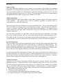
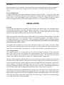
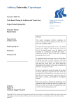
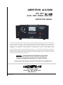
AMERITRON ALS-500M
500 WATT
SOLID STATE MOBILE AMPLIFIER
INSTRUCTION MANUAL
The Ameritron ALS-500M is a 500 watt PEP output solid state linear amplifier using rugged, conservatively rated bipolar RF
devices in the power output section. The ALS-500M operates at full power with continuous frequency coverage from 1.5
through 21.6 MHz. This amplifier requires no tuning adjustments. Broad band 5 pole filter provide output harmonic
suppression in excess of 60 dB for all frequencies above 8 MHz, and more than 70 dB on all TV channels. Export
modifications are available to extend operation to 30 MHz with a copy of a valid amateur license.
The ALS-500M uses two pairs of 2SC2879 transistors operating at 13.8 volts nominal in a push-pull output configuration.
High quality RF components combine with load fault sensing, temperature protection, and one switch frequency selection to
make this one of the simplest and easiest to operate amplifiers today. The ALS-500M operates on 13.8 Vdc electrical systems
and draws a peak current of 80 amperes at full output.
WARNING: THIS AMPLIFIER IS DESIGNED FOR USE IN VEHICLES
WITH NEGATIVE GROUND 12 VOLT ELECTRICAL SYSTEMS ONLY.
The battery should be maintained between 13.8 and 16.5 volts dc.
PLEASE READ THIS MANUAL BEFORE OPERATING THIS EQUIPMENT !
116 Willow Road
Starkville, MS 39759 USA
662-323-8211
Version 2A
Printed in U.S.A.
ALS-500M
Instruction Manual
TABLE OF CONTENTS
ALS-500M Features........................................................................................................ 1
General Information ........................................................................................................ 2
Load Fault Circuit ............................................................................................... 2
Bias Control Circuits........................................................................................... 2
Drive Power......................................................................................................... 2
Supply Voltage.................................................................................................... 3
SWR Considerations ........................................................................................... 3
Periodic Maintenance.......................................................................................... 3
Technical Assistance ........................................................................................... 3
Export Modifications........................................................................................... 4
Installation....................................................................................................................... 4
Location............................................................................................................... 4
Power Requirements ........................................................................................... 4
Fuse Holder Installation ...................................................................................... 5
Auxiliary Battery Installation.............................................................................. 5
Grounding........................................................................................................................ 6
Unibody Vehicles................................................................................................ 6
Frame-Type Vehicles .......................................................................................... 6
Interconnections Diagram ............................................................................................... 7
Interconnections .............................................................................................................. 8
Operation......................................................................................................................... 9
ALS-500M Parts List ...................................................................................................... 10
Combiner Board Parts List.................................................................................. 10
Power Amplifier Board Parts List....................................................................... 11
Output Filter Board ............................................................................................. 13
Bias Board Parts List........................................................................................... 15
Chassis Components Parts List ........................................................................... 17
i
ALS-500M
Instruction Manual
ALS-500M FEATURES
1.
Rugged devices.
The ALS-500M uses four rugged linear RF power devices.
2.
Fast warm-up time.
The ALS-500M has no vacuum tubes to warm-up.
3.
No tune operation.
Tuning adjustments are not necessary. A simple one knob selector switch permits operation on
frequencies between 1.5 and 21.6 MHz.
4.
Load Fault Protection
The PA load impedance is monitored and the amplifier is bypassed if the bandswitch setting or
external load is incorrect.
the
5.
Current meter.
The ALS-500M has a DC current meter to monitor collector current.
6.
Off/On switch.
This switch allows the amplifier to be by-passed for "bare-foot" operation without disconnecting
the high current leads.
7.
Remote Off/On control.
A separate connection on the power connector allows low current control of the amplifier Off/On
function for remote mounting.
8.
Remote A and B.
Ports A and B are for connecting the ALS-500RC. The ALS-500RC is a remote control head
that allows the amplifier to be located away from the operating station and still have access of the
front panel controls.
9.
Compact size.
The ALS-500M weighs only 7.5 pounds and measures 3 3/4"H x 9"W x 15 1/2"D .
1
ALS-500M
Instruction Manual
GENERAL INFORMATION
Load Fault Circuit
The ALS-500M features a load fault trip circuit that bypasses the amplifier if the amplifier frequency
switch is set to a lower frequency range than the exciter or if the load reflected power exceeds 70-100
watts. This circuit virtually eliminates the danger of component failures due to operating errors.
The Combiner circuit board near the PA contains the components that sense the reflected power at the
input of the low-pass filters used in the output circuit. Selecting a filter that has a cut off frequency
below the operating frequency or operating into loads with reflected power levels that exceed 70-100
watts will trip the overload and bypass the amplifier. SCR (Q5) on the Bias board keeps the amplifier
"locked out" until the POWER (ON/OFF) switch is cycled off and on.
Bias Control Circuits
The Bias board contains the temperature and bias control circuitry. The output transistor temperature is
monitored with diodes D1 and D2 on the PA module. The voltage drop across the diodes decreases as
the PA transistor temperature rises. The reduction in diode voltage with increasing temperature causes
IC 1c/d to reduce the PA base bias current supplied by Q2/3. Diodes D1/2 on the bias board limit the
available bias voltage if a failure in the bias circuit occurs.
IC 1a compares the voltage from the Power Amplifier temperature diodes to the reference voltage from
the temperature sensitivity control R28. If the temperature becomes too high (voltage too low) IC 1a
switches high and Q4 turns the cooling fan on. If the temperature continues to increase IC 1b will
eventually pull low and the voltage for the transmit relay and the bias voltage will be removed. The
THERMAL OVERLOAD LED is illuminated when the output of IC 1b is low. This circuit
automatically resets when the temperature drops to a safe operating range.
If the band switch is in the wrong position, the antenna SWR is high, or the amplifier is being driven
into non-linear operation a "load fault" will occur. When a load fault occurs gate voltage is applied to
SCR Q5. This causes Q5 to latch in a conducting state. Q5 will remain in this condition and the
amplifier's relay line will be disabled until the OFF/ON switch is cycled off and on. The LOAD
FAULT LED on the front panel is illuminated whenever SCR Q5 is in conduction and the amplifier is
bypassed from a load fault.
Drive Power
The ALS-500M normally requires much less than 100 watts of drive to produce full output power.
This drive power varies considerably with the gain of the transistors used in the amplifier and the
power supply voltage. As a general rule, exceeding 100 watts of drive for long periods of time may
cause component failures. Exceeding 70 watts of peak drive power may cause distortion and increase
the bandwidth of the transmitted signal.
2
ALS-500M
Instruction Manual
Supply Voltage
Low voltage solid state amplifiers are very sensitive to power supply voltage changes. For maximum
performance, the voltage should be maintained as high as possible consistent with component life. The
devices used in this amplifier have demonstrated excellent life with supply voltages up to 16 volts, and
will produce the rated output power at 14 volts dc. The output power will decrease by approximately
85 watts per volt as the supply voltage is lowered from 14 to 12 volts.
SWR Considerations
SWR (Standing Wave Ratio) causes higher voltages and/or currents to appear at the output connector
of the amplifier. This problem occurs with all amplifiers regardless of whether tubes or
semiconductors are used in the output stage.
The devices used in the ALS-500M have very good overload tolerance. The low pass output network
in the ALS-500M not extremely sensitive to load impedance changes. This makes the ALS-500M less
sensitive to frequency and SWR changes than many other similar amplifiers. The multiple section
output network and push-pull output configuration used in the ALS-500M also offers excellent
harmonic suppression.
The only danger presented by a high SWR is that the current and power dissipation in the output
devices may exceed safe limits. This can result in heat damage and failure of the amplifying devices.
If the SWR exceeds 2:1 the power level should be reduced until the reflected power is 60 watts or less.
At approximately 70 watts of reflected power the internal safety circuitry will disable the amplifier.
Periodic Maintenance
The lack of high voltage in this unit eliminates the chance of dirt and dust causing high voltage arcing
in this unit. The only deleterious effect of dust and dirt is a reduction in cooling efficiency. The
primary maintenance requirement is to monitor the amount of dirt and dust in the amplifier, and
remove the dust and dirt before cooling problems begin. Low pressure compressed air can be used to
blow the dust out of this amplifier whenever a noticeable accumulation of dust builds up.
A soft bristled brush and a small amount of alcohol can be used to clean stubborn dust from the fan or
the other components. Be careful not to get any cleaning compounds on relay contacts or in switches.
If it becomes necessary to perform maintenance on any switch or relay contact Ameritron. Ameritron
has free technical support for customers that wish to service their own equipment.
Technical Assistance
Ameritron has free technical information bulletins that provide assistance with the most common
operational problems. Technical assistance is also available by calling (662) 323-8211 or FAX (662)
323-6551 during our normal business hours (8:00 to 4:30 Central Time on weekdays) for questions
that are not properly addressed by the technical bulletins. Ameritron's policy is to provide complete
technical support to our customers. Before calling, please have the following information available:
1. The model and serial number the unit.
2. The date of purchase and the dealer.
3. A brief description of the station equipment and antenna system.
4. A complete description of the problem along with all meter readings.
3
ALS-500M
Instruction Manual
Written assistance is also available. Due to time delays in processing mail, please allow a minimum of
three weeks for a written reply. Send questions to: Ameritron, 116 Willow Road, Starkville, MS
39759
Export Modifications
A simple modification will allow operation on frequencies above 22 MHz. A parts kit to make this
modification is available by sending a written request for an MOD-10M export modification kit along
with a copy of your valid amateur license to the Ameritron. There is a charge for this kit. Export
models are shipped with this modification installed and have an "X" following the serial number.
INSTALLATION
Location
Do not locate this amplifier in excessively warm locations, near heater vents, or in unventilated areas
with ambient temperatures exceeding 120 degrees Fahrenheit. Be sure that air can circulate freely
around and through the amplifier cabinet. Do not obstruct the air inlet at the right front side of the
amplifier or the outlet air holes on the lower left side of the amplifier.
When not using the ALS-500M remote control head the best location for this amplifier is one that
allows the meter to be easily read and the controls accessed during operation. The length of each 13.8
volt high current cable is very important. Every consideration should be given to keeping the high
current battery lead lengths as short as practical. This includes the ground leads to the battery and the
ground lead to the vehicle's chassis.
The lengths of the remaining low current power and control cables are not critical. The relay control
lead can be made from any good quality two wire cable. Low level audio type cables sold for stereo
and VCR use are ideal for the relay connection. The RF cables should be kept as short as practical.
Power Requirements
This amplifier requires 11-18 volts positive at low current (less than 4 amperes) for the control and
bias circuits. This is a non-critical voltage. The voltage applied to the low current control line will not
affect the performance of the amplifier if it is within the specified range. The control line is the small
red wire that connects between pin 10 of the power connector and the 5 ampere fuse.
The heavy RED conductors and the black battery return and chassis ground conductors must carry the
full peak current of the amplifier. This current can reach 80 amperes on voice peaks or 40 amperes of
average current. This large current is split between the two large RED wires leaving pins 3 and 4 of the
power connector. The ground connections from pins 11 and 12 must also carry this current. It is
extremely important to minimize the voltage drop across these conductors. For maximum performance,
all of the high current leads (including the ground leads) must be kept as short as possible.
The following chart gives the approximate peak voltage drop in volts per foot of a single supply wire
with 40 amperes of current. Remember the ground wires also carry high current. This chart assumes
that the chassis ground of the vehicle has negligible resistance, and that the negative lead to the battery
is the same wire gauge as the positive supply leads. The chart on page 5 indicates the maximum length
of each individual wire for full performance:
4
ALS-500M
AWG
(single conductor)
10 gauge
8 gauge
6 gauge
4 gauge
Instruction Manual
Voltage Drop
at 40 amps
0.04 V/ft
0.025 V/ft
0.015 V/ft
0.01 V/ft
Maximum Length For
Full Performance
5 ft.
8 ft.
12 ft.
20 ft.
For best performance the voltage drop at maximum power in the high current power and ground leads
should be limited to a 0.2 volt maximum. Refer to the Interconnections section for information on the
wiring and fuse requirements of this amplifier.
Fuse Holder Installation
Included in the wire harness bag are 3 fuses and fuse holders. Install these fuse holders at the battery
or electrical system voltage source after the power harness wires have been routed to their final
destinations.
The cartridge type low current fuse holder is for the red low current power lead. Use 3AG type
(automotive glass) 5 ampere fast blow fuses for this lead. This holder is usually shipped with the lead
connected to both sides of the holder. Cut the lead in the middle and remove 1/2 inch of insulation.
Connect the short side of the holder (without a spring) to the lead from the amplifier. If a remote
on/off switch other than the ALS-500RC is used it should be installed between this fuse and the
amplifer. Connect the long side of the holder to an ignition key switched source or to a positive
battery lead. A switched source can usually be obtained from a fuse in the fuse box (radio or
accessory) or a convenient wire under the dash. Use wire nuts or solder and tape all connections.
The plug-in fuse holders and 30 ampere fuses are for the red high current power leads. Do not insert
any fuses until wiring is complete. These holders have Teflon coated 12 gauge leads. They can be
used for any size of power lead because their length is short. Solder one lead of each holder to one of
the lugs supplied. Install the lugs over the starter solenoid post that connects to the battery or over the
bolt that secures the positive battery terminal. Use a separate nut to secure the lugs to avoid disturbing
battery connections if possible.
Connect the other lead of each 30 ampere fuse holders to the heavy gauge power leads by stripping,
twisting, and then soldering the leads together. Bare wires should be wrapped with several layers of
electrical tape. Be sure to dress all amplifier leads so that they are not exposed to sharp edges, high
temperatures, or moving parts. After wiring is completed install the fuses.
Auxiliary Battery Installation
If possible, avoid the use of an auxiliary storage battery. Ameritron does not assume any liability and
does not recommend the use of an auxiliary battery. The individual installation is left entirely up to
the installer. The following suggestions will increase the safety of the installation.
The positive lead that connects the auxiliary battery to the main battery should be fused at both ends
with automotive type fuse links rated at 75 to 100 amperes. The positive power cable that connects the
5
ALS-500M
Instruction Manual
batteries should be number 6 AWG automotive type cable. The negative return can usually be made
through the chassis of the vehicle.
The battery should be securely mounted in a well ventilated area. The hydrogen gas that forms when
the battery is charging can be explosive if trapped in a confined area. Remember that hydrogen gas
rises, and it can be trapped in the top of any compartment. Vents must exit vertically above the area to
be ventilated. Ventilation holes below the battery do not remove the hydrogen gas.
The battery mounting must be secure and outside the passenger compartment of the vehicle. A poorly
secured battery can be a lethal projectile in a collision. A suitable battery box can be obtained from
marine accessory stores. WARNING: The installation of a second battery increases the hazard of
fire or explosion in an accident!!
GROUNDING
Unibody Vehicles
The amplifier ground connection should attach to a large fixed body panel of the vehicle. Never
depend on a connection made to the dash board, doors, trunk or hood of a vehicle for grounding. Use
the heaviest and shortest connections possible. The best conductors for all ground connections are
densely woven copper braiding or heavy stranded cable that is rated to safely carry 100 amperes.
Multiple ground connection points are usually superior to a single ground connection point.
The negative terminal of the battery is almost always directly grounded to the engine block of the
vehicle. This prevents the high starter motor currents from flowing through the engine and drive line
bearings. To be sure that the high amplifier current does not flow through the driveline of the vehicle,
and to minimize the voltage drop in the negative supply lead, the body (chassis) of the vehicle must be
securely grounded to the engine.
The engine block of the vehicle is almost always poorly grounded to the body of the vehicle. This is
usually accomplished by a small gauge wire that connects the negative post of the battery to the
chassis of the vehicle. Remember that the manufacturer of the vehicle calculated the size of the
grounding conductors to only handle the normal accessory electrical load of the vehicle.
Improvements to this ground are mandatory. Improving this ground will also reduce ignition noise and
help prevent interference or damage to the sensitive control devices in modern vehicles. This ground
can be improved by connecting a heavy ground wire from the chassis or frame to an engine accessory
mounting bolt (such as an alternator mounting bracket bolt) or to the same engine bolt that the
manufacturer uses for the negative battery cable.
WARNING: Never ground the negative battery post of the battery directly to the vehicle frame.
Never install a ground under any bolt unless you are sure the bolt connects to the
engine block. Be sure the bolt does not have a critical mechanical function.
The head gasket of an engine may fail and severely damage the engine if a soft lug or washer is placed
under a head bolt. Bolts can NOT be properly torqued against the soft materials used in electrical lugs.
Frame-Type Vehicles
Vehicles with frames often have rubber body mounts that insulate the body from the frame. The
vehicle designers do this to minimize noise, vibration and harshness. The bodies of vehicles that use
6
ALS-500M
Instruction Manual
insulating body mounts must have flexible strapping connected between the body and the frame at all
four corners of the body. This includes pick-up truck beds.
7
ALS-500M
Instruction Manual
8
ALS-500M
Instruction Manual
INTERCONNECTIONS
1. The negative battery lead must be disconnected from the battery post.
2. The positive battery terminal must be disconnected from the positive battery post.
3. Add a heavy ground strap from the engine block or the battery's negative lead to the chassis of the
vehicle.
4. The long heavy black ground lead on the amplifier power plug should be connected to battery's
negative ground cable terminal. Please note this cable is slightly longer than optimum for the 10
gauge wire supplied.
5. Connect the short black ground lead from the amplifier power plug directly to the vehicle's
chassis.
6. Both of the heavy red positive high current leads must be fused at the battery with two 30
ampere fuses. Each lead will carry 40 amperes peak (20 amperes average) during normal operation
of the amplifier. Two 30 ampere spade type fuses, PN 755-1730, fit into fuse holders supplied with
this amplifier. See page 5 for fuse holder installation instructions. Please note this cable is slightly
longer than optimum for the 10 gauge wire supplied.
Note: If using as a fix station with two supplies in parallel, remove the jumper from pins 3 and 4
of the power plug inside of amplifier.
7. The red low current power lead must connect to the positive battery supply through a 5 ampere
fuse, PN 755-1405. This lead will reset a LOAD FAULT condition if power is momentarily
interrupted and restored. This lead can also provide a remote operate - standby function. This can
be accomplished by connecting a remote switch in series with this lead. Connecting this lead to a
permanent voltage source without a series off-on switch will result in a battery drain of a few
milliamperes if the amplifier's POWER switch is accidentally left "ON". This lead should be
connected to a manually switched electrical system lead for controlling the off-on function, an
ignition key switched power source, or through a combination of the two.
8. Connect the RF output (antenna) of the exciter to the RF IN (SO-239) of the ALS-500M with a
good quality 50 ohm cable capable of handling 100 watts.
9. Connect the vehicle's antenna system to the RF OUT (SO-239) connector with 50 ohm coax that
will safely carry 600 watts. This is where the RF output meter or antenna connects.
10. Use a shielded audio type cable with standard male phono (RCA) connectors to connect the RLY
jack of the ALS-500M to the transceiver or transmitter normally open amplifier relay terminal.
This connection has 12 volts open circuit and supplies less than 100 mA of current when pulled to
ground. There is a back pulse canceling diode in the amplifier for exciter protection. The ALS500RC’s Relay jack has the same function. When using the ALS-500RC use the amplifier’s Relay
jack or the remote’s Relay jack, whichever makes installation easier.
9
ALS-500M
Instruction Manual
11. Plug the female multi-pin power connector onto the multi-pin male connector on the rear of the
ALS-500M chassis.
12. Reconnect the positive and negative battery leads to the battery.
OPERATION
Follow these instructions in numerical order. Consult the manual for the exciter, if necessary. Be sure
all electrical connections is properly wired and the vehicle is running with a fully charged battery. See
the Installation instructions for wiring details.
1. Set the ALS-500M front panel ON-OFF to OFF.
2. Set the amplifier's frequency range switch to the same frequency as the exciter. When using the
ALS-500RC, set the amplifier’s frequency switch to the Remote position and the remote’s
frequency range switch to the same frequency as the exciter.
3. With the amplifier still OFF transmit into the antenna with the exciter. Measure the SWR with the
transceiver's internal SWR indicator or with an external SWR indicator. Do not operate this
amplifier with an SWR greater than 2:1 or with more than 60 watts of reflected power. See the
"SWR Considerations" section on page 3.
4. Place the amplifier in the ON position with ALS-500RC remote on and amplifier off. The DC
AMPERES meter should increase slightly and the relay should "click" when the exciter is keyed.
5. Place the exciter in the transmit mode on CW, FM or RTTY. Gradually increase the output power
and observe the DC AMPERES meter. The current should be around 60 to 80 amperes at full
output. An external watt meter should indicate 400 watts or more of carrier power.
Full output levels of 400 watts CW should be obtained with drive levels of under 60 watts. Peak
envelope output levels on SSB may reach as high as 600 watts depending on voice and exciter
characteristics. The lowest IMD and splatter will be obtained if the amplifier is operated at an output
level slightly below the maximum level obtainable.
As the temperature rises the fan should start to run. If the temperature rises too far the THERMAL
OVERLOAD LED will light and the amplifier will not operate. This feature automatically resets
when the temperature reaches safe limits.
If the reflected power level is too high, the FREQUENCY selector is set to a cutoff frequency below
the transmission frequency, one PA section looses power, or the amplifier is overdriven, the LOAD
FAULT LED will light and the amplifier will not operate. The OFF-ON switch must cycled off to
reset the LOAD FAULT after the problem is corrected.
10
ALS-500M
Instruction Manual
ALS-500M PARTS LIST
Combiner Board Parts List
Designator
C101,102
C107,108
C109
C103,106
C104,105
D101,102
R101,102
R110
R103,104
R105,106
R107,108
R109
T101,102
T103
W101,102
Description
Capacitor, Trimmer, 500V, 3-12 pF
Capacitor, Ceramic Disc, 50v, .01 uF
Capacitor, Monolithic, 50v, .33 uF
Not used
Capacitor, DM15, 500 pF
Diode, 1N34A
Resistor, 3 watt, 100 ohm
Resistor, Trimpot, 2.5k
Resistor, 1/2 watt, 100 ohm
Resistor, 1/2 watt, 4.7k ohm
Resistor, Film, 1/4 watt, 2.2k
Resistor, 1/4 watt, 2.7k ohm
Pickup Transformer
Combiner Transformer
Terminal PC Board Posts
11
Part Number
204-0150
200-0416
205-2233
208-5691
300-0346
103-2100
104-2520
101-2100
101-3470
100-3220
100-3270
10-14136
11-0500-4
720-2670
ALS-500M
Instruction Manual
Power Amplifier Board Parts List
Designator
C225,226
C227,228
C237,238
C201,208,211,212-216,
229,230,235,236
C202,207,209,210,233,234
C203,205
C204,206
C217-220
C221,224
C222,223
C231,232
D201,202
HD202
L201-204
PCB
Q201-204
R201,204,211,214
R202,203,205-209,210,
212,213,215,216-220
R221-232
R233-236
R237,238
R239,240
T201
T202,203
T204,205
T206,207
W201-202
Description
Capacitor, DM19, 500v, 360 pF
Capacitor, SM19, 500v, 750 pF
Capacitor, DM19, 500v, 820 pF
Capacitor, 50v, .33 uF
Part Number
208-5688-1
208-5668
208-5381
205-2233
Capacitor, Ceramic Disc, .1 uF
Capacitor, Electrolytic, 25v, 100 uF
Capacitor, polyester, .15 uF
Capacitor, Ceramic Disc, 25v, .01 uF
Capacitor, SM15, 500v, 100 pF
Capacitor, SM15, 500v, 150 pF
Capacitor, Electrolytic, 25v, 10 uF
Diode, 1N4007
8 pin header
Ferrite Beads
Power Amplifier PC Board
Transistor, Power, 28C2879
Resistor, Metal Oxide, 3 watt, 6.8 ohm
Resistor, 1/2 watt, 10 ohm
200-0754
203-0564
201-2215
203-0416
208-5174
208-5396
203-0654
300-0266
612-0108
412-1599
862-0500-2
305-2879
103-0680
101-1100
Resistor, Metal Oxide, 3 watt, 100 ohm
Resistor, Metal Oxide, 3 watt, 33 ohm
Resistor, 1/4 watt, 10 ohm
Resistor, 1/2 watt, 18 ohm
Not used
Output Transformer
Input Transformer
Feedback Transformer
Terminal PC Board Posts
103-3100
103-1330
100-1100
101-1180
12
11-0500-1
11-0500-2
11-0500-3
720-2670
ALS-500M
Instruction Manual
13
ALS-500M
Instruction Manual
Output Filter Board
Designator
C301,308
C302,307
C303,309
C304,310
C305,311,319
C306,312,317
C313,314
C315,316
C318
C320
C321-341
D301
J301,302
L301,306
L302,307
L303,308
L304,309
L305,310
RLY301-312
RLY313
Description
not used
*Capacitor, SM-19, 1000v, 180 pF
*Capacitor, SM-19, 1000v, 270 pF
*Capacitor, SM-19, 1000v, 360 pF
*Capacitor, SM-19, 1000v, 680 pF
*Capacitor, SM-19, 1000v, 1500 pF
*Capacitor, SM-19, 1000v, 160 pF*
*Capacitor, SM-19, 1000v, 220 pF*
*Capacitor, SM-19, 1000v, 2700 pF*
Capacitor, Mica, 500 v, 27 pF
Capacitor, Ceramic Disc, 100 v, .01 uF
Diode, 1N4007
Jack, RJ45/641
Coil, Air Wound, 1/2" ID, 8.5 pass
Coil, Toroid, 8 pass
Coil, Toroid, 10 pass
Coil, Toroid, 14 pass
Coil, Toroid, 22 pass
Relay, 1PDT, 12Vdc
Relay, 3PDT 12 Vdc coil
* Critical Components
14
Part Number
252-0180
252-0270
252-0360
252-0680
252-1150
252-0160
252-0220
252-1270
250-0027
200-2100-1
300-4007
610-6028
10-13850
10-14168
10-14161
10-14214
10-14222
408-1216
408-6140
ALS-500M
Instruction Manual
15
ALS-500M
Instruction Manual
Bias Board Parts List
Designator
C401,406-421,
C402-405
D401,402
D403
FB401-405
For IC401
IC401
IC402
HD401
HD402
PCB
Q401-404
Q405
R401,416,417,424,425,429
R402,430
R403
R404,407
R405,411,414,419,422
R406
R408
R409,410,428
R412,420
R413,415,421,423,431,432
R418,426
R427
R433
Description
Capacitor, Ceramic Disc, 50v, .1 uF
Capacitor, Tantalum, 50v, .47 uF
Diode, 1N4007
Diode, Zener, 5.6 v, 1N4734
Bead, Ferrite, #43
Socket, 14 pin
LM324N
Regulator, 78L08AC, 8 V
Header, 8 pin
Header, 10 pin
PC Board
Transistor, MJF-3055
Transistor, 2N6564 (2N5064)
Resistor, 1/4 watt, 470 ohm
Resistor, 1/4 watt, 22k
Resistor, 1/4 watt, 33k
Resistor, 1/4 watt, 2.2k
Resistor, 1/4 watt, 10 Ohm
Resistor, 1/4 watt, 10k
Resistor, 1/4 watt, 56k
Trim pot, 2.5k
Resistor, 1/4 watt, 10k
Resistor, 1/4 watt, 1k
Resistor, 3 watt, 1.5 ohm
Resistor, 1/4 watt, 100 ohm
Resistor, 1/4 watt, 3.3M
16
Part Number
200-0754
203-0530
300-0266
301-4734
412-1599
625-0014
311-0324
307-0012
612-0108
612-0110
862-0500-1
305-3055
321-6564
100-2470
100-4220
100-4330
100-3220
100-1100
100-4100
100-4560
104-2520
100-4100
100-3100
103-3400
100-2100
100-6330
ALS-500M
Instruction Manual
17
ALS-500M
Instruction Manual
ALS-500M Chassis Components
Designator
J1, 2
J3
J4
B1
C1,4
C2,3
Meter
LED1
LED2
P1
SW1
Description
Jack, SO-239
Jack, RCA
Jack, Power
Fan, 12 volt, muffin, 3"
Capacitor, Ceramic Disc, 25v, .01 uF
Capacitor, Ceramic Disc, 25v, .1 uF
100 Amp Induction Meter
MV6753 Red LED
MV6753 Yellow LED
Plug, Power for J4
Switch, 12 vDC, lighted
18
Part Number
610-2126
600-1225
610-5012
410-3512
200-0416
200-0754
400-2500
320-0522-1
320-0300
610-6012
507-1357