1
/ Ra
IVIBER 917,380250
OWNER'S MANUAL
L
.....
Mulch/Discha.-x:je
o Assembly
®Operation
Customer
Responsibilities
®Service
• Adjustments
= Repair Parts
Caution:
Read and Follow
all Safety Rules
and Instructions
Before Operating
This Equipment
SAFETY RULES
PLUGTO PREVENT ACCIDENTALSTARTINGWHENSETllNG UP, TRANSPORTING,ADJUSTINGOR MAKING
CAUTION: ALWAYSDISCONNECTSPARKPLUGWIREANDPLACEWIRE_t_I"tERE
IT CANNOTCONTACTSPARK
REPAIRS.
IMPORTANT
SAFETY STANDARDSREQUIRE OPERATORPRESENCECONTROLSTO MINIMITI=THE RISK OF INJURY. YOUR UNIT IS EQUIPPEDWITH
SUCH CONTROLS. DO NOT ATTEMPT TO DEFEAT THE FUNCTIONOF THE OPERATOR PRESENCECONTROLS UNDER ANY CIRCUMSTANCES.
TRAINING:
°
Readthisoperator'smanualcarefulfy.Become familiarwith
the controlsand know howto operateyourmower properly°
Learnhowto quicklystop mower_
Do notallowchtldrento useyourmower.Neverallowadults
to usemowerwithoutproperinstructions.
•
Always stop the engine whenever you leave or are notusing
yourmower, orbefore crossingdriveways, walks, roads, and
any graveFcovered areas°
°
Never direct discharge of material toward bystanders nor
allow anyone near the mower while you are operating ito
•
Keep the area of operationclear of all persons,especially
smallchildrenandpets.
°
•
Use mower onlyas the manufacturer intendedand as describedin this manual.
Before cleaning, inspecting, or repairing your mower, stop
the engine and make absolutely sure the blade and all
moving parts have stopped. Then disconnect the spark plug
wire and keep it away from the spark plug to prevent
accidental starting.
•
Do not operate mower if it has been dropped or damaged in
any manner: Aiways have damage repaired before using
your mower'.
°
Do not continue to run your mower if you hit a foreign object.
Follow the procedure outlined above, then repair any damage before restarting and operating you mower.
•
Do not use accessory attachmentsthat are not recommended
by the manufacturer.
Use of such attachments may be
hazardous°
•
Do not change the governor settings or overspeed the
engine. Engine damage or personal injury may result.
•
Be aware that the mower blade turns when the engine is
running.
°
Do not operate your' mower if it vibrates abnormally. Excessive vibration is an indication of damage; stop the engine,
safely check forths cause of vibrationand repair as required.
I
Do not run the engine indoors. Exhaust fumes are dangerous.
•
PREPARATION:
•
•
•
•
•
Dress properly. Do not operatemowerwhen barefootor
wearingopen sandals. Wear only solid shoes with good
tractionwhenmowing.
Checkfuel tankbeforestarting engine. Do not fill gastank
indoors,whentheengine isrunningor whentheengineis hot.
Allowthe engineto coolfor severalm_nutes
beforefilling the
gas tank. Clean offanyspilledgasoltnebeforestartingthe
engine.
*
Never operate your mower without proper guards, plates,
grass catcher or other safety devices in place.
MAIN'rENANCE AND STORAGE:
•
Check the blade and the engine mounting bolts often to be
sure they are tightened properly.
•
Always make wheelheightadjustments beforestartingyour
mower. Neverattemptto dothiswhiletheengineisrunning.
Check all bolts, nuts and screws at frequent intervals for
proper tightness to be sure mower is in safe working condition_
°
Keep all safety devices in place and working.
Mow 0nly in daylight or goodartificiallight.
°
To reduce fire hazard, keep the engine free of grass, [eaves
or excessive grease and Oilo
°
Check grass catcher often for deterioration and wear and
replace worn bags. Use only replacement bags that are
recommended by and comply with specifications of the
manufacturer of your mower.
°
Always keep a sharp blade on your mower.
°
Nlow engine to cool before storing in any enclosure.
°
Never store mower with fuel in the tank inside a building
where fumes may reach an open flame or an ignition source
such as a hotwater heater, space heater, clothes dryer, otc,
OPERATION:
*
Never cut grass by putling the mower towards you. Mow
across the face of slopes, never up and down or you might
lose your footing. Do not mow excesshtely steep slopes,
Use caution when operating the mower on uneven terrain or
when changing directions - maintain good footing.
Alwaysthoroughlycheckthe areatobe mowedandclear itof
all stones,sticks,wires,bones, and otherforeign objects°
These objectswillbe thrownby the blade and can cause
severeinjury,
Alwayswearsafetyglassesor eyeshieldswhenstartingand
whileusingyourmower°
Keep youreyesand mindon yourmowerandthe areabeing
cut, Do not let otherinterestsdistractyou,
Do not mow wetorslipperygrass, Neverrun whileOperating
yourmower.Alwaysbe sureofyourfooting- keepafirm hold
on the handlesand walk,
Do not put hands or feet near or under rotating parts. Keep
clear of the discharge opening at all times.
LOOK FOR THIS SYMBOL TO POINT OUT IMPORTANT SAFETY PRECAUTIONS.
ill
ii
i
i i i 'HIIJ/llllllllHIIHIIHIllllllllllllllll"
IT MEANS
- ATTENTION!t!
BECOME
ALERT!!! YOUR SAFETY IS INVOLVED.
, i i ii
....................
II II
II
I J
I L I
I
I
IIJ JIL
IIIIIIIIJL
JLIIIIIIJLIIIILIJ[IIIIIII[ILII[I[ II
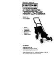
CONGRATULATIONS
on your purchase of a Sears
Craftsman Lawn Mower. It has been designed, engineered
and manufactured to give you the best possible dependability and performance.
Should you experience any problems you cannot easily
remedy, please contact your nearest Sears Service CentedDepartment. Sears has competent, well trained technicians and the proper tools to service or repair this uniL
Please read and retain this manual. The instructions will
enable you to assemble and maintain your lawn mower
properly° Always observe the "SAFETY RULES".
MODEL
NUMBER
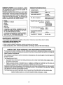
PRODUCT SPECIFICATIONS
9t7_380250
HORSEPOWER:
3.5
DISPLACEMENT:
9.06 cu. in.
GASOLINE CAPACITY:
1 o0quart
(Unleaded)
OIL (20 oz_ Capacity):
SAE 30 (Above 32°F)
5W30 (Below 32°F)
SPARK PLUG (GAP .030 in.):
(0.76 mm)
Champion
RJ19LM or
Sears 7133312
or STD 361458
or STD 360950
VALVE CLEARANCE: Intake:
Exhaust:
.008 in.
o00B in.
SOLID STATE IGNITION
AIR GAP:
.0125 in.
BLADE BOLT TORQUE:
35-40ft.-Ibs.
SERIAL
NUMBER
DATE OF
PURCHASE
THE MODEL AND SERIAL NUMBERS WILL BE
FOUND ON A DECAL ATTACHED TO THE REAR
OF THE LAWN MOWER HOUSING.
YOU SHOULD RECORD BOI"H SERIAL NUMBER
AND DATE OF PURCHASE AND KEEP IN A
SAFE PLACE FOR FUTURE REFERENCE_
MAINTENANCE
AGREEMENT
A Sears Maintenance Agreement is available on this producL Contact your nearest Sears store for details.
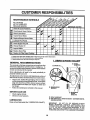
CUSTOMER
RESPONSIBILITIES
• Read and observe the safety rules.
, Follow a regular schedule in maintaining, caring for and using your lawn mower.
= Follow the instructions under "Customer Responsibilities" and "Storage" sections of this Owner's Manual.
LIMITED TWO YEAR WARRANTY ON CRAFTSMAN
POWER MOWER
For two years from date of purchase, when this Craftsman Lawn Mower is maintained, lubricated, and tuned up
according to the operating and maintenance instructions in the owner's manual, Sears will repair free of charge any
defect in material or workmanship.
If this Craftsman Lawn Mower is used for commemiat or rental purposes, this warranty applies for only 90 days from
the date of purchase.
This Warranty does not cover:.
,
Expendable items which become worn during normal use, such as rotary mower blades, blade adapters, belts,
air cleaners and spark plug.
•
Repairs necessary because of operator abuse or negligence, including bent crankshafts and the failure to
maintain the equipment according to the instructions contained in the owner's manual.
WARRANTY SERVICE IS AVAILABLE BY RETURNING THE CRAFTSMAN POWER MOWER 'lO THE NEAREST
SEARS SERVICE CENTER/DEPARTMENT IN THE UNITED STATES. THIS WARRANTY APPLIES ONLY WHILE
THIS PRODUCT IS IN USE IN THE UNITED STATES°
This Warranty gives you specific legal rights,and you may also have other rights whichvary from state to state.
SEARS, ROEBUCK AND CO. D/731CR-W SEARS TOWER, CHICAGO, IL 60684
3
TABLE OF CONTENTS
SAFETY RULES ............................................................ 2
PRODUCT SPECIFICATIONS ....................................... 3
CUSTOMER RESPONSIBILITIES ..................... 3, 10-12
WARRANTY ................................................................... 3
LAWN MOWER ACCESSORIES .................................. 5
ASSEMBLY .................................................................... 5
OPERATION .................................................................. 6
SERVICE AND ADJUSTMENTS ................................. 13
STORAGE .................................................................... 14
TROUBLESHOOTING ................................................. 15
REPAIR PARTS - LAWN MOWER ........................ 16-17
REPAIR PARTS - ENGINE ................................... 18-21
PARTS ORDERING/SERVICE ................ BACK COVER
INDEX
A
Accessories ............................................ 5
Adjustments:
Carburetor .................................. 13
Handle Height ............................ 13
Height of Cut ................................ 7
Air Filter:
Service ........................................ 12
Assembly:
Handle .......................................... 5
B
Blade:
Sharpening ................................. 11
Replacement .............................. 11
C
Controls:
Operator Presence Control Bar .6
Drive Control ................................ 6
Customer Responsibilities ..... 3, 10-12
Air Filter ...................................... 12
Blade Care/Replacement .......... 11
Engine ........................................ 12
Lubrication ................................. 10
Spark Plug ................................. 12
E
Engine:
Oil Change ................................. 12
Oil Level ..................................... !2
Oil Type ........................................ 8
Starting ......................................... 9
Storage ....................................... 14
F
Fuel:
Type .............................................. 8
Storage ....................................... 14
H
Handle:
Adjustment ................................. 13
Assembly ..................................... 5
L
Lubrication:
Engine ........................................ 10
Wheel Adjuster .......................... 10
M
Maintenance Agreement .................... 3
Mowing Tips ........................................ 9
0
Olh
Engine ........................................ 10
Storage ....................................... 14
Operation:
Operating lawn Mower ............... 6
Control Bar .................................. 6
Drive Control ............................... 6
Operator Presence Control Bar ......... 8
Options:
Attachments ................................. 5
P
Repair Parts
Lawn Mower .......................... 16-17
Engine ................................... 18-21
4
R
Responsibilities,
Customer .... 3, 10-12
S
Safety Rules ........................................
Service and Adjustments:
Carburetor ..................................
Engine Speed .............................
Handle ........................................
Spark Plug .........................................
Specifications .....................................
Starting the Engine .............................
Stopping the Engine ..........................
Storage ..............................................
2
13
13
13
12
3
9
.9
14
T
Trouble Shooting Chart ................... 15
W
Warranty .............................................. 3
Wheels:
Wheel Adjusters .......................... 7
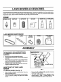
These accessories were available when this lawn mower was produced. They are also available at most Sears retail outlets,
catalog and service centers, Most Sears stores can also order repair parts for you, when you provide the model number
of your lawn mower, Some of these accessories may not apply to your lawn mower,
ENGINE
E air,0iL
hE
, ,,L,,
MUFFLER
SPARK PLUG
GAS CAN
AIR FILTER
......
' ,,i
STABILIZER
i,,,,, ,i,i
LAWN MOWER MAINTENANCE
BELT
ii
ii
i,i,illl,,,
.......................
i
ir,i
i N,ii_[i,i
I
II
I/I
i, i,jl
ll,ll,l,ll,lllll
I
Il!llfflll!!H
WHEELS
BLADE
ADAPTER
BLADE
I
I!
II
=i
J ii
ii
_IL' '
Your lawn mower has been assembled at the factory.
OPERATOR
PRESENCE
CONTROL BAR
FROM
UPPERHANDLE
CARTON
•
o
°
°
UFTUP
Remove loose parts included with mower°
Cut down two end corners of carton and lay end panel
down flat.
Remove a!tpacking materials except padding between
upper and lower handle and padding holding operator
presence control bar to upper handle°
Roll lawn mower out of carton and check carton thoroughly for additional loose parts.
MOWING POSITION
HOW TO SET UP YOUR LAWN
MOWER
TO UNFOLD
°
°
lll'_llllll_'lll
IIIIII1'11
TO REMOVE
LAWN MOWER
LAWN MOWER
COVER
LOWER HANDLE
FIG. 1
HANDLE (See Fig. 1)
Raise handles until lower handle section locks into
place in mowing position.
Raise upper handle section into place on lower handle,
remove protective padding and tighten both handle
knobs°
°
o
5
Remove handle padding holding operator presence
control bar to upper handle.
Your lawn mower handle can be adjusted for your
mowing comfort° Refer to "Adjust Handle" in the
Service and Adjustments section of this manual.
OPERATION
:z:::z:.....
.
........
...................................
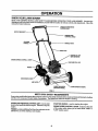
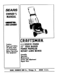
KNOW YOUR LAWN MOWER
READ THiS OWNER'S MANUAL AND SAFETY RULES BEFORE OPERATING YOUR LAWN MOWER. Compare the
iUustrationswith your lawn mower to familiarize yourself with the location of various controlsand adjustments, Save this
manual for future reference,
OPERATOR PRESENCE
CONTROL BAR
UPSTOP BRACKET
ENGINEZONE
CONTROL CABLE
STARTER
HANDLE
HANDLE KNOB
CABLE CLIP
ENGINEOIL CAP
WITH DIPSTICK
ENGINE SPEED CONTROL I._VER
GASOUNE FILL CAP
PRIMER
DISCHARGE GUARD
AIR RLTER
WHEEL ADJUSTER
LAWN MOWER HOUSING
(ONEACHWHEEL)
FIG. 2
.................
_
IlUl
ill
I
I111 !J
I['111
['lllllJllllll
I I'll
I
MEETS CPSC SAFETY REQUIREMENTS
Sears rotarywalk-behind power lawn mowers conformto the safety standards of the American National Standards Institute
and the U,S. Consumer Product Safety Commission. The blade turns when the engine is running.
WIHI[
II
....
illlll
OPERATOR PRESENCE CONTROL BAR - must be held
down tothe handleto start the engine. Release tostopthe
engine.
I
Ill
Illll
II
i
i_ I
I! ...........
i_i_ .................................
STARTER HANDLE - used for starting the engine,
ENGINE SPEED CONTROL LEVER - located on the side
of the engine which allows you to select either "HIGH" or
"LOW" engine speed,
PRIMER - pumpsadditional fuel from the carburetorto the
cylinder for use when starting a cold engine,
6
O
HOW TO USE YOUR LAWN MOWER
LOWERWHEELS
FOR HIGH CUT
L____ _
TO ADJUST CUTTING HEIGHT (See Fig. 3)
,
o
o
i
RAISE WHEELS
FOR LOW CUT
_
Raise wheels for low cutand lowerwheels for highcut°
Wheels are set in low cut for shipping. Adjust cutting
height to suit your requirements. Medium position is
best for most lawns°
To change cutting height, squeeze adjuster lever toward wheel. Move wheel up or down to suit your
requirements. Be sure all wheels are in the same
setting.
..........
...... I
FIG, 3
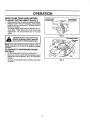
CAUTION: Do not run your lawn mower
without discharge guard, approved
grass catcher or mulcher plate in place.
DISCHARGE
NOTE: Your lawn mower has been shipped ready for
mulching operation. To convert to discharging or bagging
operation:
TO CONVERT TO DISCHARGING
MOWER
(See Fig. 4)
o
o
•
Lift discharge guard and remove mulcher plate°
Mower can now be used for side discharging or grass
catcher can now be attached° See "To install Grass
Catcher".
To returnto mulching operation, reinstall mulcherplate
as shown.
FIG, 4
7
GUARD
UlH_//
................
ii,ul
iu Ill
IlllllJ_/II
Ill
......:
:..................
:
Illlllll
I
LI
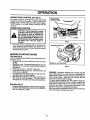
OPERATION
I,HII_III
: L....................
ENGINE
SPEED
llllllLI
CONTROL
(See Fig. 5)
ENGINESPEED
CONTROLLEVER
The engine speed is cordroUed by a lever (red knob)
located on the side of the engine° ' HIGH' position is for
starting engine, normal cut*Jngand better grass bagging.
"LOW" position is for light cutting, trimming and fuel
economy.
ENGINE
ZONE
ill l lJ
CONTROL
CAUTION: Federal regulations require
an engine control to be installed on this
risk
blade contact
Do not unlawnofmower
in orderinjury,
to minlmlze
the
der any circumstances attempt to defeat the function of the operatorcontrol.
The blade turns when the engine is
running.
•
PRIMER
FIG. 5
Your lawn mower is equipped with an operator presence control bar which requires the operator to be
positioned behindthe lawn mower handle to start and
operate the lawn mower.
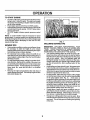
BEFORE
STARTING
GASOLINERLLER CAP
ENGINE
OIL (See Fig. 6)
A 20 oz, bottle of Pennzoil SAE 30 oil is included with your
new lawn mower,
•
Remove engine oil cap and fill to the FULL line on the
dipstick,
°
Use 2O ozs. of oiL Fortype and grade of oitto use, see
"ENGINE" in the Customer Responsibilities section of
this manual.
•
POUR OIL SLOWLY, DO NOT OVER FILLo
•
Check oil level before each use. Add oil ifneeded. Fill
to FULL line on dipstick.
•
To read proper level, tighten engine oil cap each time.
= Reinstall engine oil cap and tighten.
° After the first two (2) hours of mowing,change the oil,
and every 25 hours thereafter. You may need to
change the oil more often under dusty, dirty conditions.
ENGINE OIL CAP W/DIPSTICK
FIG, 6
WARNING: Experience indicates that alcohol blended
fuels (called gasohol or using ethanol or methanol) can
attract moisture whichleads to separation and formation of
acids during storage. Acidic gas can damage the fuel
system of an engine while in storage.
To avoid engine problems, the fuel system should be
emptied before storagefor 30 days or longer. Drainthe gas
tank, star_the engine and let it run until tile fuel lines and
carburetor are empty. Use fresh fuel next season. See
Storage instructionsfor additional information.
Never use engine or carburetor cleaner productsin the fuel
tank or permanent damage may occur.
GAS (See Fig. 6)
•
Fill gasoline tank with fresh, clean unleaded gasoline.
DO NOT USE PREMIUM GASOLINE, BE CAREFUL
NOT TO OVER FILL TANK.
8
OPERATIC
TO START ENGINE
-
•
°
=
To start a cold engine, push primerfive (5) times before
trying to starL Use a firm push,. This step is not usually
necessary when starting an engine which has already
run for a few minutes°
Push engine speed control lever to HIGH position,
Hold operator presence control bar down tothe handle
and pull starter handle quickly° DO NOT allow starter
rope to snap back.
To STOP engine, release operator presence control
bar,
Max 1/3
NOTE: In cooler weather it may be necessary to repeat
priming steps_ In warmer weather over priming may cause
floodingand engine wil! not start. Ifyoudoflood enginewait
a few minutes before attempting to start and DO NOT
repeat priming steps.
FIG. 7
MULCHING
MOWING TIPS
•
•
°
.
MOWING TIPS
IMPORTANT:
FOR BEST PERFORMANCE,
KEEP
MOWER HOUSING FREE OF BUILT-UP GRASS AND
TRASH. CLEAN UNDERSIDE OF MOWER HOUSING
AFTER EACH USE. SEE "CLEANING" IN CUSTOMER
RESPONSIBILITIES SECTION OF THIS MANUAL.
° The special mulching blade will recut the grass clippings many times and reduce them in size so that as
they fall onto the lawn they willdisperse into the grass
and not be noticed. Also, the mulched grass will
biodegrade quickly to provide nutrients for the lawn.
Always mulch with your highest engine (blade) speed
as this will provide the best recutting action of the
blades.
Undercertain conditions, suchasvery tall grass, it may
be necessary to raise the height of cut to reduce
pushing effort and to keep from overloading the engine
and leaving clumps of grass clippings,
For extremely heavy cutting, reduce the width of cut
and raise the rear of the lawn mower housing one (1)
wheel adjuster setting higher than the front for better
discharge of grass°
For side discharge mowers, cutting ina counter-clockwise direction, starting at the outside of the area to be
cut, spreads grass clippings more evenly and puts less
load on the engine. To keep clippingsoff of walkways,
flower beds, etc, make the first cuts in a clockwise
direction.
Keep top of engine around starter clear and clean of
grass clippings and chaff. This will help engine air flow
and extend engine life.
-
-
o
°
9
Avoidcuttingyourtawnwhenitisweto Wet grass tends
toform clumpsand interferes with the mulching action.
The best time to mow your lawn isthe early afternoon.
At this time the grass has dried and the newly cut area
will not be exposed to the direct sun.
For best results, adjust the lawn mower cutting height
so that the lawn mower cuts off only the top one-third
of the grass blades (See Fig. 7).
If the lawn is
overgrown itwillbe necessary to raise the height of cut
to reduce pushing effort and to keep from overloading
the engine and leaving clumps of mulched grass. For
extremely heavy mulching, reduce your width of cut,
mow slowlyand raise the rear of the lawn mower one
wheel adjuster setting higher than the front.
Certain types of grass and grass conditions may require that an area be mulched a second time to completely hide the clippings. When doing a second cut,
mow across or perpendicular to the first cut path°
Change your cuttingpattern from week to week. Mow
northto south one week then change to east to west the
next week° This will help prevent matting and graining
of the lawn.
CUSTOMER
Check for Loose Fasteners
MuC,eani,nspect
Grass
Catche
V p ......
_j
IV'
W_ECleanlnspectLawn"'MowerMower
Blade ......................
V'
VP
"_
R i,,,,Replace/Shamen
MowerBlade
Check Engine Oil Level
iN
II
Change Engine Oil
Inspect Muffler
N
Replace Spark Plug
E
Replace ,A!r Filter Paper Cartridge
'.................
,.If
.................
...... b_/'3 .....
Lubricate Pivot Points
iE
"
.=
V _
......
V'
_
V_1,2
V p
.............
----.........
......
}V p
...................................
1- Changemore oftenwhenoperatingundera heavyload or In hlghambienttemperatures,
2- Se_ce moreoftenwhenoperatingIn dirty or dustyconditions.
8 - ReplacebladesmoreoftenwhenmewingIn sandysoil,
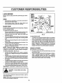
LUBRICATION CHART
GENERAL
RECOMMENDATIONS
@ _EEL
The warranty on this lawn mower does not cover itemsthat
have been subjected to operator abuse or negligence. To
receive full value fromthe warranty, operator must maintain
mower as instructed in this manual.
_) ENGINEOIL
ADJUSTER
Some adjustments will need to be made periodically to
pmpedy maintain your unit°
All adjustments in the Service and Adjustments section of
this manual should be checked at least once each season.
•
•
Once a year, replace the spark plug, clean or replace
airfilter element and checkblade forwear. A newspark
plug and clean/new air filter element assures proper
air-fuel mixture and helps your engine run better and
last longer.
Follow the maintenance schedule in this manual.
BEFORE
°
°
/
_) BRAKESPRING
BRACKET
EACH USE
DISCHARGE
GUARD
HINGE PIN
Check engine oil level.
Check for loose fasteners,
(_) SPRAY LUBRICANT
(_) SAE3OMOTORO|L REFERTO ENGINE - CUSTOMERRESPONSIBILITIESSECTION,
LUBRICATION
Keep unit we!l lubricated (See "LUBRICATION CHART").
IMPORTANT
DO NOT Of L OR GREASE PLASTIC
WHEEL BEARINGS. VISCOUS LUBRICANTS WILL
ATTRACT DUST AND DIRT THAT WILL SHORTEN THE
LIFE OF THE SELF LUBRICATING BEARINGS. IF YOU
FEEL THEY MUST BE LUBRICATED, USE ONLY A DRY,
POWDERED GRAPHITE TYPE LUBRICANT SPARINGLY.
10
CUSTOMER
BILITmES
11111
I
LAWN MOWER
II
II
nanceo
TIRES
o
,,,
i
,,,,i
.....
_!!
!_!
ADAPTER
Keep tires free of gasoline, oil, or insectcontrolchemicals which can harm rubber.
Avoid stumps, stones, deep ruts, sharp objects and
other hazards that may cause tire damage.
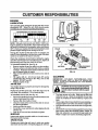
BLADE
IIII
CRANKSHAFT &
BLADE
ADAPTER
DETAIL
BLADE
Always observe safety rules when performingany mainte-
o
J
I_Y
CRANKSHAFT
CARE
Forbest results, mowerblade must be kept sharp_ Replace
bent or damaged blades.
BOLT
CRANKSHAFT
KEYWAY
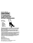
TO REMOVE BLADE (See Fig. 8)
Remove spark plug wire from spark plug and place wire
where it cannot come in contact with spark plugo
°
Turn lawn mower on its side. Make sure air filter and
carburetor are up.
Use a wood block between blade and mower housing
to prevent blade from turning when removing blade
bolt.
o Protect your hands with gloves and/or wrap blade with
heavy cloth.
°
Remove blade boltbyturning counter-clockwise. Use
a 9116"box or open-end wrench.
°
Remove blade and attaching hardware (bolt, lock
washer and hardened washer).
LOCK WASHER
BLADE ADAPTER
FIG. 8
TO SHARPEN BLADE
o
NOTE: Remove the blade adapter and check the key
inside hub of blade adapter. The key must be in good
conditionto work properly. Replace adapter if damaged.
The blade can be sharpened with a file or on a grinding
wheel. Do not attempt to sharpen while on the mower.
To checkblade balance, drivea nailintoa beam orwatL
Leave about one inch of the straight nail exposed.
Place center hole of blade over the head of the nail. If
blade is balanced, it should remain in a horizontal
position, if either end of the blade moves downward,
sharpen the heavy end untiethe blade is balanced.
GRASS
CATCHER
(If purchased as an accessory)
•
TO REPLACE BLADE (See Fig° 8)
o
Position the blade adapter on the engine crankshaft.
Be sure key in adapter and keyway in crankshaft are
aligned.
°
Positionblade on the blade adapter aligningthetwo (2)
holes in the blade with the raised lugs on the adapter.
°
BesurethewordTOP (stampedontheblade) istoward
the engine.
°
lnstallthe blade boltwiththelockwasherand hardened
washer into blade adapter and crankshaft.
°
Use block of wood between blade and lawn mower
housing and tighten the blade bolt, turning clockwise.
•
The recommended tighteningtorque is 35-40 ft. Ibs.
IMPORTANT: BLADE BOLT IS GRADE 8 HEATTREATED_
°
Use only Sears authorized replacement blade to get the
best cutting results.
NOTE: We do not recommend sharpening blade- but ifyou
do, be sure the blade is balanced°
11
The grass catcher may be hosed with water, but must
be dry when used.
Check your grass catcher often for damage or deterioration. Through normal use it will wear. If catcher
needs replacing, replace only with a manufacturer
approved replacement catcher from Sears° Give the
lawn mower model number when ordering°
ER RESPONSIBILITIES
ENGINE
LUBRICATION
Use only high quality detergent oil rated with API service
classification SG. Select the oil's SAE viscosity grade
according to your expected operating temperature.
RECOMMENDEDSAEVISCOSITYGRADES
°F .20 o
oC.29 o
0o
-18 °
32 °
0o
60 °
160
80°
270
100°
38°
CONTAINER
NOTE: Although multi-viscosity oils (5W30, 10W30 etc.)
improve starting in cold weather, these multi-viscosity oils
will result in increased oil consumption when used above
32°F. Check your engine oil level more frequentlyto avoid
possible engine damage from running low on oil.
FIG. 9
COLLAR
Change the oil after the first two hours of operation and
every 25 hours thereafter or at least once a year if the lawn
mower is not used for 25 hours in one year.
Check tile crankcase oil level before starting the engine
and after each five (5) hours of continuous use°Tighten oil
plug securely each time you check the oil level.
SLOT
TO CHANGE ENGINE OIL (See Fig. 9)
,, Remove engine oil cap; lay aside on a clean surface.
.
Tip lawn mower on its side and drain oil into a suitable
container. Rocklawn mowerbackandforthtoremove
any oil trapped inside of engine.
•
Wipe off any spilled oil on lawn mower and on side of
engine.
•
Fill engine with oil. All oil must meet API service
classification SG. Fill only to the "FULL" line on the
dipstick. DO NOT overfill.
•
Replace engine oil cap°
AIRRLTER
FIG, 10
CLEANING
IMPORTANT:
FOR BEST PERFORMANCE,
KEEP
MOWER HOUSING FREE OF BUILT-UP
GRASS AND
TRASH.
CLEAN THE UNDERSIDE
OF YOUR MOWER
AFTER EACH USE.
Your engine will not run properly and may be damaged by
using a dirty air filter.
Replace the air filter every year, more often if you mow in
very dusty, dirty conditions° Do not wash air' filter.
l&
TO CHANGE AIR FILTER (See Fig. 10)
•
•
°
°
Removethe air filter by turningcounterclockwise tothe
stop and pull away from collar.
Remove fitter'from inside of cover.
Clean the inside of the cover and the collar'to remove
any dirt accumulation.
Insert new filter'into cover.
°
•
°
Put air filter cover and filter into collar aligningthe tab
with the slot.
•
Push in on covet and turn clockwise to tighten.
MUFFLER
°
Inspect and replace corroded muffler as it could create a
fire hazard and/or damage.
SPARK PLUG
Change your spark plug each year to make your engine
start easier and run better. Set spark plug gap at .030 inch.
TURNCLOCKWISE
TOTIGHTEN
AIRRLTERCOVER
AIR FILTER
,,
COUNTERCLOCKWISE
TO REMOVE
12
from spark plug and place wire where it
cannot
come
in contactspark
with the
CAUTION:
Disconnect
plugspark
wire
plug.
"rum lawn mower on its side, Make sure air filter' and
carburetor are up_ Clean the underside of your lawn
mower by scraping to remove build-up of grass and
trash.
Clean engine often to keep trash from accumulating. A
clogged engine runs hotter and shortens engine life.
Keep finished surfaces and wheels free of all gasoline°
oil, etc.
We DO NOT recommend using a garden hose to clean
lawn mower unless the electrical system, muffler, air
filter and carburetor are covered to keep water out.
Water in engine can result is shortening engine tife_
ERVICE AND ADJ
_1111111111,1,11,,
,, 'ii
.......................
CAUTION: BEFORE PERFORMING ANY SERVICE OR ADJUSTMENTS:
•
Release control bar.
° Make sure the blade and all moving parts have completely stopped.
°
Disconnect spark plug wire from spark plug and place where it cannot come in contact with plug
LAWN MOWER
TO ADJUST
CUTTING
SHIPPING POSITION
HEIGHT
MEDIUMLOW
MEDIUM HIGH
See "TO ADJUST CUTTING HEIGHT" in the Operation
section of this manual°
REAR DEFLECTOR
The rear deflector, attached between the rear wheels of
your mower, is provided to minimize the possibilitythat
objects will be thrown out of the rear of the mower into the
operator mowing position. If the deflector becomes damaged, it should be replaced,.
DISCHARGE
G
GUARD
The discharge guard attachedtothedischarge opening of
your lawn mower, is provide d to prevent the possibility of
injury resulting from objects being thrown out of the discharge opening into the operator mowing position+ If the
discharge guard becomesdamaged, it shoutdbe replaced+
FIG, 11A
FIG. 11B
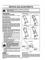
TO ADJUST HANDLE
(See Figs. 11 thru 13)
LOW
Your lawn mower handle can be raised or lowered for your
mowing comfort. Four (4) positions are available: high,
medium.high, medium low and low. Handles are shipped
mounted in the medium tow position.
•
To change from medium low to medium high position,
the upper and lower handle sections willhave to be
turned over (See Fig. 11B).
°
Remove the controls and operator presence control
bar from the upper handle,
°
Remove the starter rope guide from the lower handle.
•
_Removehairpin cotters.
°
Disconnect the lower handle from the handle brackets
_See Fig. 13).
°
/urn the handle over and reassemble the hairpin
cotters that have been removed.
°
Reassemble the starter rope guide.
°
Reassemble the controls and the operator presence
control bar to the upper hand!e,.....................
FIG. 12A
FIG. 12B
CAUTION: The operator presence control bar must pivot freelyto permit blade
brake engagement when control bar is
released. Do not overUghten the fasteners holding the controls to the upper handle.
.......
•
°
To change from medium !ow to h!ghpos_ion only the
upper handle section will have to be turned over (See
Fig. 12A).
To change from medium tow to low position, only the
lower handle section will have to be turned over (See
Fig. 12B)o
HAIRPINCLIP
MOUNTING
BRACKET
FIG. 13
ENGINE
ENGINE SPEED
CARBURETOR
The engine speed has been factory set. Do not attempt to
increase engine speed as it may result in personal injury°
lfyou believethe engine is runningtoo fast ortoo slow, take
your lawn mower to an authorized Sears service center for
repair and adjustment,
Your carburetor has a non-adjustable fixed main jet for
mixture control, if your engine does not operate properly
due to suspected carburetor problems, take your lawn
mower to an authorized Sears Service Centerfor repair and
adjustment.
13
IIII!
I
IIIIJ±L±HII
IL
II
ENGINE
Immediately prepare your lawn mower' for storage at the
end of the season or if the unit will not be used for 30 days
or more.
FUEL SYSTEM
IMPORTANT: IT IS IMPORTANT TO PREVENT GUM
DEPOSITS FROM FORMING IN ESSENTIAL FUEL
SYSTEM PARTS SUCH AS CARBURETOR, FUEL FILTER,
FUEL HOSE, OR TANK DURING STORAGE.
ALSO,
EXPERIENCE ffqDtCATES THAT ALCOHOL BLENDED
FUELS (CALLED GASOHOL OR USING ETHANOL OR
METHANOL) CAN ATTRACT MOISTURE WHICH LEADS
TO SEPARATION AND FORMATION OF ACIDS DURING
STORAGE. ACIDIC GAS CAN DAMAGE THE FUEL
SYSTEM OF AN ENGINE WHILE IN STORAGE°
•
Drain the fuel tank_
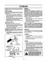
LAWN MOWER
When lawn mower is to be stored for a period of time, clcan
it thoroughly, remove aIt dirt, grease, leaves, etc. Store in
a clean, clryarea_
* Clean entire lawn mower (See "CLEANING" in the
Customer Responsibilities section of this manual).
Lubricate as shown in the Customer Responsibilities
section of this manual.
.
-
Be sure that all nuts, bolts, screws, and pins are
securely fastened. Inspect moving parts for damage,
breakage and wear. Replace if necessary.
Touch up. all rusted or chipped paint surfaces; sand
lightly before painting.
•
•
°
HANDLE (See Fig. 14)
NOTE: Fuel stabilizer is an acceptable alternative in
minimizing the formation of fuel gum deposits during storage° Add stabilizer to gasoline in fuel tank or storage
container. Always follow the mix ratio found on stabilizer
container. Run engine at least 10 minutes after adding
stabilizerto allowthe stabilizer to reach the carburetor. Do
not drain the gas tank and carburetor if using fuel stabilizer.
You can fold your'lawn mower handle for storage_
o
Squeeze the bottom ends of the lower handle toward
each other until the lower handle clears the handle
bracket, then move handle forward.
-
Loosen upper handle mounting bolts enough to allow
upper handle to be folded back.
IMPORTANT:
WHEN FOLDING THE HANDLE FOR
STORAGE OR TRANSPORTATION, BE SURE TO FOLD
THE HANDLE AS SHOWN OR YOU MAY DAMAGE THE
CONTROL CABLES.
°
Start the engine and let it run until the fuel lines and
carburetor are empty.
Never' use engine or carburetor cleaner products in the
fuel tank or permanent damage may occur,
Use fresh fuel next season.
ENGINE OIL
Drain oil (with engine warm) and replace wit|) clean engine
oil. (See "ENGINE" in the Customer Responsibilities
section of this manual),
When setting upyour handle fromthe storageposition,
the lower handle will automatically lock into the mowing position.
CYLINDER
•
•
•
Remove spark plug.
Pour one ounce (29 ml) of oil through spark plug hole
into cylinder.
Pull starter handle slowly a few times to distribute oil,
•
Replace with new spark plug.
OTHER
*
,
HAIRPIN
COTTER
Do not store gasoline from one season to another.
=Replaceyour gasoline can if your can starts to rust.
Rust and!or dir_ in your gasoline will cause problems.
o If possible, store your unit indoors and cover it to give
protection from dust and dirt.
°
Cover your unit with a suitable protectiye cover that
does not retain moisture. Do not use plastic. Plastic
cannot breathe which allows condensation to form and
willcause your unit to rusty
IMPORTANT:
NEVER COVER MOWER WHILE ENGINE
AND EXHAUST AREAS ARE STILL WARM.
MOUNTINGPIN
OPERATOR PRESENCE
,_F_D
CAUTION: Never store the lawn mower
BAClG",tARD
MOWING
ing where fumes may reach an open.
with
gasoline inAllowl[he
the tank inside
a buildfiameorspark.
engineto
cooJ
before storing in any enclosure.
POSITION
LOWER HANDLE
FIG. 14
14
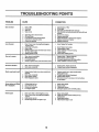
I
I
PROBLEM
u
CAUSE
CORRECTION
1.,
2,
3.
4o
Dirtyair filter.
Out of fuelo
Stale fuel.
Water in fuel
1.
2.
3.
4.
5,
6.
7.
8,
9,
Sparkplug wireisdisconnected.
Badsparkplug.
Loessbladeor brokenblade adapter,,
Controlbarin releasedposition
Controlbardefectivs
5.
6_
7.
8.
9_
Clean/replaceair filter.
Fillfuel tank.
Draintankand refillwith fresh cleanfuel.
Drainfuel tankand carburetorandrefilltankwith fresh
gasoline.
Connestwire toplugo
Reptacesparkplug.
Tightenblade boltor replacebladeadapter.
Depresscontretbar to handle.
Replacecontrolbar.
I.
Setin 'HigherCut" position.
2.
3.
4.
5.
6_
Set in "Higher Cut"position°
Cleanlraplacealrfilter.
Cleanunderside ofmower housing°
Checkoil level.
Cut at stowerwalkingspeed.
Replaceblade. Tighten bladeboil
Seta!l wheels atsame height,
Setanglnespeed controlin HIGH position.
Cleanunderside of mowerhousing.
=,,i,_,l
Does not start
,,],,,,,,],,,,,,,,,,]llU_l]ll
]111 i
boss of power
I
_'"11i'1_1
UgUIII'II'I'"I"IIII]'
1,, Rearof lawnmower housing/bladedragging
in heavygrass°
2, Cuttingtoomuch grass,
S. Dirtyair filter,
4., Buildupof grass, leavesand trashundermower°
5, Toomuchoilin engine.
6. Walkingspeedtoo fast.
,,,,,,,,,,
,,,, ,,,,,,,,,,,,,,,,,,,
,,,,,,
,,
............
IIIIIIIII
I
iiii
!1
I!1111111
II ,
1.
2,
3,
4,
Wom, bentor loossblade.
Wheelheightsuneven.
Low engine speed.
Buildupof gross, leaves,and trash undermower,
i.
2,
3o
4.
Excessivevibration
1,
2.
Worn,bentor loose blade,
Bent enginecrankshaft.
t, ReplacebladeoTightenblade bolt.
2_ ContactSears Ser,'iceDapartmenL
Starter rope hard to pull
'11
II
_1,111111
i1,111,
ili,i,i,i,,il ,, i, iLi'i
I. Engineflyv&eelbrake is on whencontrolbarts
released.
2. Bentenginecrankshaft
3. Bladeadapter broken.
4. Bladedragging
ingrass,
2,
8,
4.
Grass catcher not filling
(If so equipped)
14
2o
3o
4_
1o
2.
3o
4.
Hard topush
1_ Grassis too highorwheelheight istoo low.
2. Rearof lawnmower housing/blade
dragging
in grass.
8. Grasscatchertoofull
4, Handleheight positionnot rightforyou,
Cuttingheighttoolow.
Litton bladeworn off_
Catchernot ventingair.
Lowengine speed_
15
t.
_i
i
I
I
I
I
uiii
Poorsut-uneven
iiii ilU, ii1_ iii,
I
li
'l]'i iiHi'
Depress control barto upper handle before
pulling starter rope.
Contact Sears Service DspartmenL
Replace blade adapter.
Move lawn mower to cut grass or to hard surface
to start
engine,
Raisecuttingheight.
Replaceblade_
Cleangrasscatcher.
Set enginespeedcontrolin HIGH position.
i. Raise cuttingheight.
2o Raise rearof lawn mower housing one(1)
settinghigher°
3. Emptygrasscatcher.
4o Adjusthandleheightto suiL
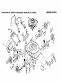
CRAFTSMAN
REPAIR PARTS
20" ROTARY LAWN MOWER- -MODEL NO. 917.380250
27
9
56
1(
12
25_2_6
_8
2?
26
27
4
2O
22
17
20
25
18
31
27
28
27 26
3,3
28
_--41
24
23
T/_
40
57
40
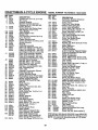
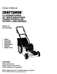
CRAFTSMAN
KEY
NO.
__1
20" ROTARY LAWN MOWER--MODEL
PART
NO.
DESCRIPTION
1
2
3
4
5
6
7
8
9
10
11
12
13
14
15
17
18
20
21
22
23
24
25
26
27
28
29
86902
850991X479
86899X004
750097
STD541425
851664
53109
85827
STD54t425
63688
751228
81276
87584X004
63644X417
63645X417
850904
84920
87877
850855X004
85021X004
62335
64921
750500
52160
85179
800090
850998
30
48177
Control Bar
Upper Handle
Up-Stop Bracket
Hex Wsh. Head Screw #10-24 x 1/2
Locknut 1/4-20
Engine Zone Control Cable
He× Head Bolt 1/4-20-!-1/2
Cable Clip
Locknut 1/4-20
Handle Knob
Rear Skirt
Self Tapping Screw #10-24 x 1/2
Skirt Bracket
Handle Bracket Assembly (Right)
Handle Bracket Assembly (Left)
Wheel Adjusting Bracket
Spacer
Selector Knob
Selector Spring
Axle Arm Assembly
Be!levilleWasher
Shoulder Bolt
Wheel and Tire Assembly 7-1/2 x 1-1/2
Washer
Retainer Clip
Hubcap
Hex Head Thread Rolling Screw
3/8-16 x 1
Lawn Mower Housing Kit (lncl. Ref.
31
87575X479
Front Baffle
#31, 43)
REPAIR PARTS
NO. 917.380250
KEY
NO.
PART
NO,
DESCRIPTION
32
33
35
751592
61537
851084
36
37
38
39
40
41
42
43
44
45
46
47
48
49
50
51
52
54
56
850263
851074
752233
850977
55187
88272X479
88271X479
85463
51793
33750
87590
87589
87593
750149
84676X479
58714
103672X
87576X479
131692
57
----
751772X417
131989
751214
132115
Locknut 3/8-16
Washer
Hex Head Machine Screw 3/8-24 x !- 3/8
(Grade 8)
Heiical Lockwasher 3/8
Hardened Washer
Blade 20" Mulching
Blade Adapter
Self Tapping Screw 5/16-18 x 3/4
Handle Support Bracket (Right)
Handle Support Bracket (Left)
Danger Decal
Hairpin Cotter
E-Ring
Hinge Rod
Torsion Spring
Housing Bracket Assembly
Discharge Guard
Lower Handle
Handle Bolt
Rope Guide
Rear Baffle (Not Shown)
Engine - Craftsman Model Number
143.424052 or 143.414232
Mulcher Plate
Decal, Discharge 2 in ONE
'EAGER 1" Decal
Owner's Manual
Available accessories not included with lawn mower:
71 33072
Grass Catcher
7tw33623
Gas Can (2.5 gal.)
7133500
Fuel Stabilizer
7133300
SAE BOW Oil (20 oz.)
71__.33722
High Wheel Kit
71 33316
Mower Cover
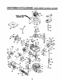
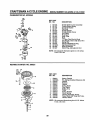
CRAFTSMAN 4-CYCLE ENGINE
...............................................
400
MODEL NUMBER
143.424052
,
& 143.414232
,,, , ,,
...................................................
110_f
-7
189
194
195
370C
215
t
42
2O5
\
41
2O4
i
I
I
I
i
223
/
182
185
t
241
245
/80
/
178
<
260
18
CRAFTSMAN 4..CYCLE ENGINE
MODEL NUMBER 143.424052
REF
NO.
1
2
6
7
REF PART
NO. NO.
135 35395
8
9
PART
NO.
34975
26727
33734
34214A
33735
30200
12A
12B
14
15
16
17
'18
19
20
30
40
33886
34695
28277
30589
31383A
31335
650548
31361
32600
34473A
34514
34515
34516
41
325388
325488
325498
42
43
45
46
48
50
52
69
7O
72
73
28986
28987
28988
20381
309_38
32610A
27241
33148A
29914
35261
3565tB
30572
28833
75
80
81
82
83
84
86
89
90
92
93
100
10t
103
26208
30574
30590A
30591
30588A
29193
650488
611004
611112
650815
650816
34443A
6'10118
6508I4
110
119
120
125
34961
299530
34335
293130
293150
126 293148
293150
130
6021A
DESCRIPTION
Cylinder Assy. (tncl. #2, 8, 9 & 20)
Pin, Dowel
Element, Breather
Breather Assembly (Includes
Reference #6, 8, 9,12A and 12B)
* Gasket, Breather
Screw, Seres, Hex Washer Head,
Self-Tapping #10-24 x 9/16
Tube, Bl;eather
Elbow, Breather Tube
Washer, Rat
Rod, Governor (Includes Ref. #14)
Lever, Governor
Clamp, Governor Lever
Screw, Hex Wash. Hd'. #8-32 x 5/16
Spring, Extension
Seal, Oil
Crankshaft Assembly
Piston, Pin & Ring Assembly, Std.
Piston, Pin & Ring Assyo .010" over
Piston, Pin & Ring Assy..020" over
(Assemblys Include #41,42 and 4.3)
Piston & Pin Assembly, Standard
Piston & Pin Assembly o010 over
Piston & Pin Assembly .020" over
(Assemblys Include Reference #4.3)
Ring Set, Piston, Standard
Ring Set, Piston .010" oversize
Ring Set, Piston .020" oversize
Ring, Piston Pin Retaining
RodAssy. Connecting (tncL #46)
Bolt, Connecting Rod
Valve, Lifter
Camshaft, Compression Release
Pump Assembly, Oil
* Gasket, Mounting Range
Range, Mount. (IncL #72,73,75,80)
Plug, Oil Drain {Includes Ref. #73)
* Gasket, Oil Drain Plug (Not
Required With Plastic Oil Plug)
Seal, Oil
Shaft, Governor
Washer, Rat
Gear A ssy., Governor (Incl. #81)
Spool,Governor
Rmg, Retaining
Screw, Seres, Hex 114-20 x 1ol/4
Key, Flywheel
Flywheel
Washer, Belleville
Nut, Flywheel
Solid State Assembly
Cover, Spark Plug
Screw, Seres, T-t5, Torx, Hex
Washer Head #10..24 x 1
Wire, Ground
* Gasket, Cylinder Head
Head, Cylinder
Valve, Exhaust, Standard Size
Valve, Exhaust, 1132"oversize
Valve, Intake, Standard Size
Valve, Intake, 1/32" oversize (All
Valves Include Reference #151)
Screw, Hex Flange 5/16-18 x 1-I/2
150
151
169
172
174
178
182
184
185
186
189
31672
31673
27234A
32755
650128
29752
6201
26756
31384A
34358
650839
190
191
192
193
194
195
200
35831
350408
34966
34965
32309
610973
35727
202
203
204
205
207
215
223
224
238
33802
31342
650549
650777
34336
32410
650451
34690A
650932
239
241
245
250
260
262
34338
35797
35066
35065
35478
65083'I
275
277
285
287
290
292
300
301
305
306
3O7
309
27181B
650795
35000
650884
34357
26460
35586
35355
35577
34265
35499
650562
310 35578
313 34080
327 35392
3700 35167
380
632046A
390
590686
400
33238D
& 143.414232
DESCRIPTION
Spark Plug, Resistor (Champion
RJ-19LM or Equivalent)
Spring, Valve
Cap, Lower Valve Spring
* Gasket, Valve Spring Box
Cover, Valve Spring Box
Screw, Seres, Hex #10-24 x 1/2
Nut & Lock Washer 114-28
Screw, Hex Head 1/4-28 x 7t8
* Gasket, Carburetor
Pipe, Intake (Includes Ref. #224)
Link, Governor Spring
Screw, Hex Washer Read,
Powerlok 1/4-20 x 3/8
Lever, Brake
Bracket, S.E. Brake (Includes #195)
Link, Control
Spring, Extension
Rlng,-Retaining
Terminal Assembly
Control Assembly, Speed .(Includes
Reference NumlSers 202 thru 205)
Spring, Compression
Spring, Compression
Screw, Fiilister Head #5-40 x 7/16
Screw, Fillister Head #6-32 x 21/32
Link, Throttle
Knob, Control
Screw, Sems, Hex Head 1/4-20 x 1
* Gasket, Intake Pipe
Screw, Hex Wasl_er Head,
Shoulder #10-32 x 49/64
* Gasket, Air Cleaner
Collar, Air Cleaner
Rlter, Air Cleaner, Paper
Cover, Air Cleaner
Housing, Blower
Screw, Hex Washer Head,
Powerlok Thread 1/4-20 x 15132
Muffler (Includes Reference #277)
Screw, Hex Head 1/4-20 x 2-1/4
Hub, Starter
Screw, Hex Wash. Hd. #8-32 x 'I/2
Line, Fuel
Clamp, Fuel Line
Tank Assembly (lncL #292 & 301)
Cap, Fuel
Tube, Oil RII
Gasket, Fill Tube
"O" Rin-.q
Screw, Flex Washer Head,
Shakeproof #10-32 x 1/2
Dipstick, Oil Fill
Spacer, Flywheel Key
Plug, Starter
Decal, Instruction
Carburetor (Includes Ref. #184)
Starter, Rewind
Gasket Set (IncL items marked *)
RPM Settings: High Speed: 2900-3200, Low: 2450-2750
*Indicates Parts Included in Gasket Set, Reference #400
NOTE: All component dimensions given in U.S. inches
1 inch = 25.4 mm
19
CRAFTSMAN 4=CYCLE ENGINE
MODEL NUMBER
143.424052
IIIIIIIIIIIIIIIIIIIIIIIIIIIII1'111111111'11'1
CARBURETOR
III
& 143.414232
IIIII
II
III
IIIIIIIIIIIII
IIIIIIIIIIIIII
NO. 632046A
REF PART
NO. NO.
DESCRIPTION
1
2
4
5
6
7
16
25
27
28
29
30
31
35
40
44
48
Throttle Shaft & Lever Assembly
Throttle Return Spring
Dust Seat Washer
Dust Seal
Throttle Shutter
Throttle Shutter Screw
Fuel F_ing
Roat Bowl
Shaft, Float
Float
"O" Ring, Roat Bowl to Body
Inlet Needle, Seat & Clip (incl. #31)
Spring Clip
Primer Bulb/Retainer Ring
High Speed Bowl Nut
Bowl Nut Washer
Welch Plug, Atmospheric Vent
2
35
631615
631767
631184
631971
631616
650506
632527
631700
631024
632019
631028
631021
631022
632047
631937A
631334
631027
NOTE: All component dimensions given in U_S. inches
1 inch = 25_4 mm
REWIND STARTER
NO. 590621
REF PART
NO. NO.
-1
2
3
4
5
6
7
8
9
10
11
12
13
590621
590599A
590600
590615
590601
590598
590616
590617
590618
590619
590620
590622
590535
590452
DESCRIPTION
Starter, Rewind
Pin, Spring (Includes Reference #4)
Washer
Retainer
Washer
Spring, Brake
Dog, Starter
Spring, Dog
Pulley
Spring, Rewind
€over, Spdng
Housing Assembly, Starter
Rope, Starter (98" long, 9/64" dia.)
Handle, Starter
NOTE: All component dimensions given in U.S. inches
1 inch = 25.4 mm
20
SERVICE NOTES
21
•
SERVICE NOTES
22
SERVaCE NOTES
23
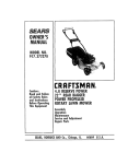
CRRFT$ I:IN®
OWNER'S
MANUAL
3.5 HORSEPOWER
20" SIDE DISCHARGE
2 in One Mulch/Discharge
ROTARY LAWN MOWER
Each Lawn Mower has its own model number. Each
engine has its own model number.
The model number for your lawn mower will be found on
a decal attached to the rear of the lawn mower housing.
MODEL NO.
917.380250
The model number'for the engine will be found on the
Blower Housing of the engine a_jacent to the spark plug.
All parts listed here in may be ordered through Sears,
Roebuck and Co. Service Centers and most Retail
Stores.
WHEN ORDERING REPAIR PARTS, ALWAYS GIVE THE
FOLLOWING INFORMATION:
- PRODUCT - "ROTARY LAWN MOWER"
- MODEL NUMBER - 917.380250
• ENGINE - CRAFTSMAN - MODEL NO. 143.424052
HOW TO ORDER
REPAIR PARTS
OR 143.414232
,, PART NUMBER
• PART DESCRIPTION
Your Sears merchandise has added value when you
consider that Sears has service units nationwide
staffed with Sears trained technicians.,,professional
technicians specifically trained on Sears products,
having the parts, tools and the equipment to insure that
we meet our pledge to you, we service what we sell,
132115
......................................
02/27/92
Printed in U.S.A.
Revo2
,,
,,,,, ,,,,
,,,,,,,,,,,,
,,,,,,,,,,,