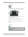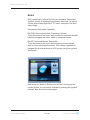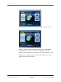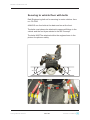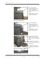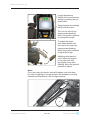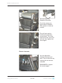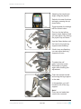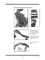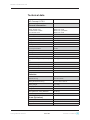
1
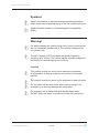
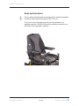
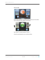
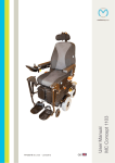
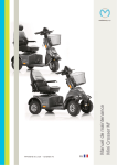
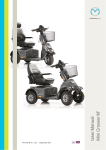
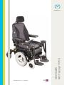
User Guide MC Concept 1170 II medemagroup P9-0270-B ver. 2.0.4 - May 2013 GB Medema Production A/S Serial number: ______________________________ Delivery date: ________________ Year 20______ This vehicle was supplied by: User guide P9-0270-B Date: 2 of 56 / Version 2.0.4/2013 Medema Production A/S Contents Symbols.................................................................................. 4 Warning! ................................................................................. 4 Seat and backrest ................................................................. 5 Introduktion............................................................................ 6 Declaration of conformity ..................................................... 7 Part names ............................................................................. 8 Introduction DX2.................................................................... 9 Joystick parts ........................................................................ 9 Operating................................................................................ 9 Error Code .............................................................................. 16 Extra........................................................................................ 17 Safety check........................................................................... 19 Serial number......................................................................... 20 Driving the MC Concept 1170 II ............................................ 21 Brakes..................................................................................... 25 Fuses ...................................................................................... 26 Batteries ................................................................................. 27 Battery disposal..................................................................... 27 Charging ................................................................................. 28 General care ........................................................................... 29 Service intervals .................................................................... 29 Insurance................................................................................ 29 Storage ................................................................................... 30 Transporting by motor vehicle ............................................. 30 Transporting by plane ........................................................... 31 Towing .................................................................................... 31 Changing the wheels............................................................. 32 Changing the battery............................................................. 34 Changing lights ..................................................................... 37 Lap belt ................................................................................... 37 Securing to vehicle floor with belts ..................................... 38 Footplate/footrest .................................................................. 40 Adjusting the headrest.......................................................... 47 Swing-away fitting ................................................................. 47 Adjusting the Spinalus backrest .......................................... 48 Adjusting the ION seat .......................................................... 49 Reconditioning ...................................................................... 50 Technical data ........................................................................ 52 Own notes .............................................................................. 54 User guide P9-0270-B 3 of 56 Version 2.0.4/2013 Medema Production A/S Symbols Used in the manual to indicate sections describing situations where extra care is required owing to the risk of personal injury. Used to indicate sections on electromagnetic compatibility (EMC). Warning! For safety reasons the vehicle must not be lent to persons who are not completely familiar with it. The vehicle is designed for one person only. The MC Concept 1170 II has been designed for persons weighing up to 155 kg. The vehicle can be specially adapted at the factory for users weighing up to 200 kg. Joystick The joystick control box must not be exposed to extremes of temperature or kept in a damp environment for extended periods. The joystick control box must not be subjected to heavy knocks. Do not switch off the control box while driving, except in an emergency, as this may damage the electronics. For cleaning, use a damp cloth with slightly soapy water. Do NOT allow any water or moisture to enter the control box. User guide P9-0270-B 4 of 56 Version 2.0.4/2013 Medema Production A/S Seat and backrest All our seats and backrests are produced in materials resistant to ignition and tested according to ISO 7176-16. The cover of the seat and backrest can be washed in the washing machine. ALWAYS follow the washing instructions on the back of the seat pad / backrest. User guide P9-0270-B 5 of 56 Version 2.0.4/2013 Medema Production A/S Introduktion Congratulations on your new MC Concept 1170 II electric mobility scooter. You are now the owner of an electric mobility scooter developed for use indoors as well as outdoors. It is what is called a Class B vehicle according to the European classification of electric scooters. To get the best out of this vehicle - and to avoid breakdowns and accidents - we recommend that you read this User Manual carefully. If you are a new user, you should pay particular attention to the section “Driving the MC Concept”. The MC Concept 1170 II is designed to stay safe to use for at least 10 years, up to a maximum of 5,000 hours, providing it has service and safety inspections every year, which is equivalent to around 500 operating hours. The service must be carried out either by Medema Danmark A/S or an authorised workshop. IMPORTANT! For safety reasons it is of the utmost importance that service and safety check intervals are complied with, as this minimises the risk of brake failure and short-circuits in the wiring, which could generate heat and cause a fire. We offer a wide range of accessories for the MC Concept that can make everyday life easier for you. You are always welcome to contact us for further information on special accessories and adaptations. Medema Production A/S is not responsible for any damage or injuries caused by inappropriate or unsafe use of the MC Concept. If you have any further questions about the MC Concept or this User Manual, you are always welcome to get in touch. Our contact details are as follows: Mini Crosser A/S Phone: +45 70 10 20 54 Email: [email protected] Internet: www.minicrosser.dk NB: Errors and omissions excepted. We reserve the right to update this manual as required. User guide P9-0270-B 6 of 56 Version 2.0.4/2013 Medema Production A/S Declaration of conformity Medema Production A/S hereby declares that: Machine: MC Concept Use: (Prescribed use in User Manual) Model No: 1170 II Complies with the Medical Device Directive 93/42/EEC.. This product has been tested and approved according to standard EN 12184 electric wheelchairs, scooters and their chargers. The product is risk analysed in accordance with the harmonized standard DS/EN ISO 14971 - Medical devices - Application of risk management to medical devices. The scooter can, for a fee, be taken to the nearest dealer for disposal in accordance with current environmental regulations. User guide P9-0270-B Manufacturer: Medema Production A/S Address: Enggårdvej 7, DK-7400 Herning Tel./Fax +45 7010 2054 Date: 12.04.2010 Signature: _____________________ 7 of 56 +45 9716 8582 Version 2.0.4/2013 Medema Production A/S Part names The part names given below refer to the descriptions later in the instruction manual. Headrest Adjusting the headrest Swing-away release Joystick Control panel Armrest Charging socket Release for leg supports Thermal fuse to right of serial number plate Serial number on vehicle Finger screw to loosen seat Disengagement lever Pivot wheel Eye for restraints Footplate or footrests Central wheel Leg length adjustment Anti-tilt wheel INFO! Jazzy 1170 II is prepared for transport bracket. User guide P9-0270-B 8 of 56 Version 2.0.4/2013 Medema Production A/S Introduction DX2 DX2 is the first in a new generation of joysticks to control the electric wheelchair. With its large color LCD screen and its logical icon built menu structure, it directs the user to the target. Joystick parts Dynamic DX2 AJR 1 2 3 5 6 4 7 8 1 Start/stop button 2 Indicator left 3 Indicator right 4 Select 5 Display 6 Speed selector 7 Accessory Selector 8 Horn Operating At the top of the display you will find the status bar. Battery indicator is displayed constantly. The clock can be turned on or off as you wish. The other is lit when the corresponding function is active. 1 User guide P9-0270-B 2 3 4 5 6 1 Battery indicator Green = fully charged Yellow = least half full Red = almost empty - charge now! 2 Indicator left is active When hazard warning lights are active, both icons blinks. 3 Lights on 4 Error code - see section on error codes. 5 Indicator right is active When hazard warning lights are active, both icons blinks. 6 Real time 9 of 56 Version 2.0.4/2013 Medema Production A/S Clock on/off Press arrow up/down or joystick (push forward) until the above icon is showed in the center of the screen. Use ”Select” to switch between X and . Accept by pressing the arrow up/down button. User guide P9-0270-B 10 of 56 Version 2.0.4/2013 Medema Production A/S Set Speed When you turn the joystick on, the image shown below will be presented in the display. The number in the centre shows the speed you have chosen as max speed. Change the Speed by selecting the plus / minus key. Maximum speed is 5, lowest is 1. Chosen speed Select Find the features in the bottom with the “Select” button. Setting the seat - back and leg supports Chosen speed Select Press the arrow up / down until the image shows the chair. Use the “Select” to choose the function you want modified. Use the joystick to change example angle of the seat back. User guide P9-0270-B 11 of 56 Version 2.0.4/2013 Medema Production A/S Function Icon Seat angle (Tilt) Backrest angle Seat height Left footrest Right footrest footrest both Lying down Headrest Only the available options will be displayed. User guide P9-0270-B 12 of 56 Version 2.0.4/2013 Medema Production A/S Light on / off Push the arrow up / down until the image for light is shown in the centre. Push the joystick forward to turn the light on. And again to turn of the light. Push the joystick back to activate the hazard warning lights. Push the joystick back again to turn it of. Push the joystick right or left to activate the indicators right or left. Turn of the indicators by puching the joystick to the same side again. Setting the Backlight Press the arrow up / down until the sun i shown i the centre. Push the joystick forward to enter the settings. Use the Select button or joystick right / left to change the brightness. Use Joystick forward / back or arrow up / down to accept the new settings and return to the main menu. User guide P9-0270-B 13 of 56 Version 2.0.4/2013 Medema Production A/S Setting the display environment Use the arrows up /down until “day / night” icon i shown in the centre. Push the joystick forward to enter settings. The image below will show. 1 2 3 Exit / Cancel Exit / Cancel Setting Result 1 - Indoor The display will show a black background color. 2 - Outdoor The display will show a white background color. 3 - Automatic The background color will change (black/white) accordingly to the surrounding light. Use ”Select” or joystick right / left to select setting. Push the joystick forward to accept the new settings and return to the main menu. If you push the Joystick back or use the arrow up / down, the new setting will be dismissed and you will return to the main menu. User guide P9-0270-B 14 of 56 Version 2.0.4/2013 Medema Production A/S Setting the Clock Use arrow up / down until the clock is shown in the centre. Push the joystick forward to enter settings. The image below will show. Press the Select button or push the joystick right / left to choose the digit to change. Joystick forward make the number count forward. Joystick back accept the new settings and return to the main menu. Arrow up / down dismiss the new settings and return to the main menu. System lock To lock the DX system Press the on / off button, for 4 sec. while the system is turned on. The system will now shut down in locked condition. User guide P9-0270-B 15 of 56 Version 2.0.4/2013 Medema Production A/S To unlock the DX system Press the on / off button. The system will show a lock in the display. Press the horn twice within 10 seconds. The system will boot normally. Error Code Code Cause Meaning 1 Could mean: - Errors in programming - Error in wire connection - Internal fault in a module DX Module Turn off the chair and turn on again. If it doesn’t works, contact qualified technician (HMC or therapist). 2 DX Accessory Could mean: - driving slowly because of raised seat. (programming). Not an arror. Lower the seat as much as possible. If it doesn’t works, contact qualified technician (HMC or therapist). 3 Motor 1 / L (M1) Could mean: - Loose connection from the engine to power module - Short circuit Check that no plug is loose. Contact competent technician (HMC or therapist). 4 Motor 2 / L (M2) Could mean: - Loose connection from the engine to power module - Short circuit Check that no plug is loose. Contact competent technician (HMC or therapist). 5 Parking brake 1 (M1 left) Could mean: - Loose connection - Short circuit Check that no plug is loose. Contact competent technician (HMC or therapist). 6 Parking brake 2 (M2 right) Could mean: - Loose connection - Short circuit Check that no plug is loose. Contact competent technician (HMC or therapist). User guide P9-0270-B 16 of 56 Version 2.0.4/2013 Medema Production A/S Extra DX2 joystick can, using a DX Infra-red Interface Transmitter System, control all electronic equipment, that work via remote control with infrared light. Be it TV, radio, computer mice and other things. Accessories that make it possible: DX-IRIS2 Infra-red Interface Transmitter System To be Mounted on the chair, and are able to communicate with infrared-equipped television, radio or computer mouse. DX-MTX Infra-red Mouse Transmitter To be Mounted on the chair, and are able to communicate with an infra-red computer mouse. This makes it possible to navigate the mouse around on a PC screen using the joystick. See below. Use arrow up / down to find the mouse icon. As long as the mouse is blue, it is not active. Activate by pushing the joystick forward. Now the mouse turns green. User guide P9-0270-B 17 of 56 Version 2.0.4/2013 Medema Production A/S Use the joystick to move the mouse on the computer screen. Use the “Select” button to make a mouse click. It works the same way as the mouse. You can make single clicks and double clicks, depending on what your PC is configured to use. Disable mouse again using the arrow up / down button. New feature can now be selected. User guide P9-0270-B 18 of 56 Version 2.0.4/2013 Medema Production A/S Safety check Daily safety check: The electronic system has an integrated safety check which runs up to 100 times per minute. To supplement this check, you should carry out the following regular checks. Switch off the electronic system (no lights in the display) Check if the joystick is bent Check if the joystick is damaged in any other way Check that it returns to the central position when you release it If the check reveals any problems, contact a competent service engineer before using the scooter again. Weekly safety check: Parking brake: This test must be carried out on a flat surface with at least one metre of free space around the scooter. Start the scooter and slowly move the joystick forward. There is a clicking sound. (The scooter may start to move in this setting). Immediately release the joystick and listen for the clicking sound, which should occur within one second. Repeat in all directions. Check that the rubber bellows around the joystick is intact. This is important, as the bellows prevent moisture getting into the electronic system. Check that the control box is properly secured. If the check reveals any problems, contact a competent service engineer before using the scooter again. Monthly check Check the tyre pressure at least once a month. It should be 2,1 bar. User guide P9-0270-B 19 of 56 Version 2.0.4/2013 Medema Production A/S Annual: The MC Concept 1170 II is designed to stay safe to use for at least 10 years, up to a maximum of 5,000 hours, providing it has service and safety inspections every year, which is equivalent to around 500 operating hours. The service must be carried out either by Medema Danmark A/S or an authorised workshop. IMPORTANT! For safety reasons it is of the utmost importance that service and safety check intervals are complied with, as this minimises the risk of brake failure and short-circuits in the wiring, which could generate heat and cause a fire. Serial number All scooters have a serial number plate showing the year of production, month and serial number. The same serial number can also be found on the front of the User Manual. Please quote this number when making inquiries about servicing, spare parts, etc. Maximum user weight Unladen weight of vehicle incl. batteries and seat Serial number Year and month of production Position of serial number plate on vehicle. User guide P9-0270-B 20 of 56 Version 2.0.4/2013 Medema Production A/S Driving the MC Concept 1170 II MC Concept is a modern device, specially developed to help you achieve maximum mobility. Before getting on or off the vehicle, you must check the following: That the wheelchair is switched off. That the wheelchair is not disengaged. That the wheelchair and the seat you are moving to are both stable. Avoid placing your full body weight on the footrests. This may tip the wheelchair forwards. If you are using the MC Concept for the first time, you should try out all the day-to-day situations you are likely to encounter: inclines/declines, driving on rough terrain driving on sloping terrain. You should practice these manoeuvres with your therapist or other carer. Warning! The seat should NEVER be hoisted while driving on uneven surfaces, slopes or up and down kerbs. The higher the seat is raised, the more unstable the chair becomes. Arms and legs While driving, you must place your arms on the armrests and your feet on the footrests. Cables and leads Always make sure that cables and leads from components like the joystick are fixed using ties. User guide P9-0270-B 21 of 56 Version 2.0.4/2013 Medema Production A/S Changes of level Never attempt to climb onto raised objects or kerbs higher than 10 cm. Always approach changes of level head on, with the front and back wheels moving in a straight line. (See below.) This reduces the possibility of tipping. Fig 1 Fig 2 Fig 3 Fig 4 Driving on hills When driving on hills, you should try to keep the scooter moving all the time. If you have to stop, start up again slowly. When driving downhill, you must drive at the slowest speed. If the MC Concept starts moving faster than you want, stop it by completely releasing the joystick. Carefully push the joystick forwards again and carry on with care until you reach the bottom of the hill. User guide P9-0270-B 22 of 56 Version 2.0.4/2013 Medema Production A/S 11 tips for driving the MC Concept: Reduce the speed when turning corners and going downhill. Reduce the speed when driving on inclines. Maximum incline: 6° = 10% Reduce the speed when driving on a sideways incline. Maximum sideways incline: 10° Avoid driving and parking in the rain Avoid parking on snow and ice. Always park on a level (flat) surface. Avoid driving on rough ground. Avoid driving on icy surfaces, or smooth surfaces (for example snow or freshly mown grass) Never attempt to climb kerbs higher than 10 cm. Avoiding driving over kerbs diagonally. There is a risk of tipping over. Not to be used for towing other vehicles, etc. Note! Talk to your doctor if you are taking medicine that may affect your ability to drive motorised vehicles. Do not drive the MC Concept when intoxicated. This applies to both medicine and alcohol. User guide P9-0270-B 23 of 56 Version 2.0.4/2013 Medema Production A/S Driving on public roads: When driving on public roads, footpaths, pedestrian streets, car parks, shopping centres, etc. you must make sure you adjust your speed and distance for other users. At 7 km/h you must follow the traffic rules applicable to cyclists. This also means that your lights must be switched on during lighting-up time. (Optional extra) On footpaths, the maximum speed is 6 km/h. In this situation you are regarded as a pedestrian. Note! You should assume that other road users cannot see you while you are sitting in the MC Concept. So take great care and wait for the road to clear before crossing. Driving on stairs/escalators: The scooter is not designed for use on stairs or escalators and any attempt to do so may cause serious injury to yourself and others. Electromagnetic compatibility (EMC) The MC Concept 1170 II satisfies the requirements for the use of scooters in an environment with electromagnetic noise. There may, however, be rare situations in which electromagnetic noise can affect the MC Concept 1170 II. Sources of such noise include radio and television stations, amateur radio transmitters and mobile phones. If such equipment is being used close by, you are recommended to switch off the MC Concept. Avoid using a mobile phone while driving. If the MC Concept starts making unintended movements or if the brakes are released, turn the MC Concept off as soon as it is safe to do so. In rare cases a MC Concept can set off shop alarms. Dynamic’s control systems have been tested and meet the requirements of ISO7176/14 and EN12184. User guide P9-0270-B 24 of 56 Version 2.0.4/2013 Medema Production A/S Brakes The MC Concept is equipped with two sets of brakes: The motor brake and the parking brake. Motor braking: When you drive downhill, the control unit of the MC Concept applies the motor brake. Parking brake: When the vehicle is stationary and the joystick is not moved, a magnetic brake is automatically applied to each drive unit. For driving, the magnetic brake is released first, after which the MC Concept can be driven as described above. Note! You must NEVER brake the MC Concept by switching off with the I/O button while moving, as this applies the magnetic brake with considerable force, with a resulting risk of tipping. Disengagement: The MC Concept is equipped with one disengagement lever on the back of the vehicle. Warning! When the scooter is disengaged, the braking system is deactivated. You must NEVER disengage on sloping terrain. This can lead to serious damage or personal injury. Normal position for driving (Tilt the lever out a little and turn up). User guide P9-0270-B 25 of 56 Position for disengagement (Tilt the lever out a little and turn down). Version 2.0.4/2013 Medema Production A/S Fuses If the indicator light flashes to indicate overheating: Switch off the vehicle Wait for 3 minutes Restart On the right of the MC Concept behind the seat, there is a thermal fuse protecting the battery circuit. The fuse is white. If it pops out, you can push it back in again after a few minutes. If it immediately pops out again, contact your authorised dealer. There are no external fuses that need to be replaced. The thermal fuse is here. User guide P9-0270-B 26 of 56 Version 2.0.4/2013 Medema Production A/S Batteries The battery indicator shows how much power is available to the scooter. Red, amber and green indicate that the batteries are fully charged. Red and amber indicate that the batteries will soon need recharging. Red indicates that the batteries need to be recharged as soon as possible, otherwise the scooter will cut out. The MC Concept’s batteries should be charged while not in use. This extends the service life of the batteries. The MC Concept is supplied with sealed, maintenance-free batteries that do not normally generate gas and do not need to be topped up with water. Note! Unsealed batteries must NEVER be installed in the MC Concept. If charging is to take place outdoors, an enclosed charger without a fan should be chosen. Only use chargers designed for charging dry maintenance-free GEL batteries. Max. charging current 12 A. The charging cable must NOT be extended. New batteries can be purchased from Medema Danmark A/S. Battery disposal Used batteries must be disposed of through your supplier or at a recycling centre. Take care in handling any leaky batteries, as they contain corrosive acid bound into the gel mass. INFO: New batteries can be purchased from Medema Danmark A/S. User guide P9-0270-B 27 of 56 Version 2.0.4/2013 Medema Production A/S Charging Charging 1 Plug the cable into the control box on the scooter. 2 Plug the charger into the outlet or switch it on. 3 Use the indicator lights on the charger to check that charging has started. 4 When charging has finished, switch off or unplug the charger, and then remove the charger cable from the control box. The actual battery indicator on the vehicle will show “full” after charging for a short time. However, the batteries are not fully charged until the indicator on the CHARGER turns green. Note! New batteries reach full capacity after approx. 20 discharge/ charge cycles. Please note that the capacity of the batteries will reduce over time and at low temperatures. Battery capacity at -10°C is half that at +20°C. If the MC Concept is not going to be used for an extended period, charging once a month will suffice. Note! The charger must NOT be placed on the seat during charging. Charging while the vehicle is switched on User guide P9-0270-B The battery indicator will flash during charging. After charging, the battery indicator will flash for about 1 minute after the charging cable is unplugged. 28 of 56 Version 2.0.4/2013 Medema Production A/S General care If you get food or drink, etc. on the control unit, you should wipe it with a damp cloth. You must only use a damp cloth to clean the MC Concept. Note! Using a high-pressure cleaner or hose may damage the scooter’s electronic system. Service intervals The MC Concept is designed to require a minimum of maintenance. However, you are recommended to take it to your dealer for an annual inspection. IMPORTANT! For safety reasons it is of the utmost importance that the servicing and safety check intervals are complied with, as this minimises the risk of brake failure and short-circuits in the wiring, which could generate heat and cause a fire. (For further information see the Service Manual.) Insurance A MC Concept with a maximum speed of 10 km/h is in the eyes of the law a bicycle, and no separate insurance is required. Most contents/home insurance policies include third-party liability insurance for cyclists and so also cover MC Concept users. We recommend that you talk to your insurance company about this when the vehicle is delivered. If necessary, comprehensive insurance will have to be taken out separately. User guide P9-0270-B 29 of 56 Version 2.0.4/2013 Medema Production A/S Storage The scooter should be stored and charged under cover, preferably at temperatures above 10° C. Note! The charger must be kept dry, but should not be covered when in use. For long-term storage we recommend covering the MC Concept 1170 II to protect it from dust, rain and sunlight. Transporting by motor vehicle The MC Concept 1170 II must ALWAYS be secured while being transported. To lift the scooter, use the pivot wheels at the front and back. Avoid lifting by the seat or side panels. Secure it in the vehicle with belts attached to the two eyes at the front and two at the back. All the eyes are marked in yellow. Eyes for restraints User guide P9-0270-B 30 of 56 Version 2.0.4/2013 Medema Production A/S Transporting by plane To transport the MC Concept by plane, the airlines require: the batteries to be aircraft approved the air to be let out of the tyres the battery leads to be disconnected (not always, but frequently). A main switch can be fitted (optional extra). A battery declaration for air travel can be found on the Mini Crosser website: http://www.minicrosser.dk/Download_brochurer.asp Towing If you should be unfortunate enough to break down, the MC Concept can be towed or pushed. The MC Concept must always be turned off and disengaged for towing. See the section on Brakes. To tow the MC Concept, secure a rope to the tow fitting on the front - marked in yellow. Do not tow faster than 5 km/h. The scooter will generate electricity when it is towed, with the motors acting as dynamos. If it is towed at more than 5 km/h, there is a risk of the motors generating enough electricity to damage the scooter and, in the worst case, cause a fire. Eyes for restraints User guide P9-0270-B 31 of 56 Version 2.0.4/2013 Medema Production A/S Changing the wheels If you get a puncture in one of the pneumatic tyres or if a tyre is so badly worn that it needs to be replaced, follow the instructions below. Tyres and inner tubes can be purchased from the authorised dealer who supplied the MC Concept. The MC Concept must be TURNED OFF before you start. Jack up the MC Concept onto a block of wood so that the wheels are clear of the floor/surface. Anti-tilt wheel Undo and remove the middle nut. You will now be able to work the wheel loose. Pivot wheel Undo and remove the middle nut. You will now be able to work the wheel loose. User guide P9-0270-B 32 of 56 Version 2.0.4/2013 Medema Production A/S Central wheel. You are recommended to contact your resource centre, etc. to obtain the correct tools. Use a screwdriver to prise off the cover plug. Remove the nut with a 17 attachment. (Use a new nut when reassembling). You may need to use a wheel puller, as the wheel may be very difficult to remove. Replace the wheel with a washer and a new nut. Apply Loctite 243 (blue) to the thread. Push the cover plug back on. User guide P9-0270-B 33 of 56 Version 2.0.4/2013 Medema Production A/S Changing the battery This is how to remove the batteries without using tools. Always switch off the power on the MC Concept before starting work. Raise the bellows. Remove the two plugs behind the seat. Undo and remove the two finger screws behind the seat. If the MC Concept has leg supports, these must also be removed along with their plugs. These are on the right and left of the seat. See the descriptions below. Manual central footplate Undo the screws on both sides and remove the footplate. User guide P9-0270-B 34 of 56 Version 2.0.4/2013 Medema Production A/S Manual leg supports Press the trigger and lift of the leg supports. Electric leg supports Push the catch down. Then twist the leg support out to the side. You will now be able to lift it off. There are no external fuses that need to be removed. Electric central footplate Remove the plug under the seat on the right. Undo the screws on both sides and you will be able to remove the footplate. User guide P9-0270-B 35 of 56 Version 2.0.4/2013 Medema Production A/S You can now tilt the seat forward for access to the batteries. Remove the plus and minus terminals from both batteries. Loosen the strap around the batteries. The batteries can now be replaced. Take care not to trap any cables when fitting the new batteries. Keep hold of the seat while tilting it backwards. Battery strap User guide P9-0270-B Terminal 36 of 56 Version 2.0.4/2013 Medema Production A/S Changing lights In case one of the lights stop working: Check the power supply. Replace light module. 1 * For mounting on the other side: Mount bracket inverted. * REMEMBER! Red light should turn backward. * * * Pos Art. No. Description Qty 1 CR-5-0000 Blink and position lights, LED, complete 1 Note! Lights are extra. Lap belt Is there is a need for it you can, as an accessory, mount a lap belt or harness belt on MC Concept 1170 II. Lap belt User guide P9-0270-B 37 of 56 Version 2.0.4/2013 Medema Production A/S Securing to vehicle floor with belts Dahl Engineering belt set for securing in motor vehicles. Item no. C2-0242 ALWAYS use four belts at the back and two at the front. The belts must always be attached to approved fittings in the vehicle and the four eyes welded to the MC Concept. The belts MUST be attached within the angles shown in the picture for optimum safety. 30˚ User guide P9-0270-B 45˚ 60˚ 38 of 56 40˚ Version 2.0.4/2013 Medema Production A/S Attachment point Attachment point 25˚ 10˚ Min. 150 mm on floor User guide P9-0270-B Centre line 39 of 56 Min. 150 mm on floor Version 2.0.4/2013 Medema Production A/S Footplate/footrest Manual central footplate To adjust the footplate to a comfortable angle for the legs, undo the screws shown here. You can now adjust the footplate. REMEMBER to tighten the screws properly again. To adjust the angle of the actual footplate, use the set screw under the footplate. To adjust the footplate up and down, undo the screws shown here. You can now adjust the footplate to the required height. REMEMBER to tighten the screws properly again. User guide P9-0270-B 40 of 56 Version 2.0.4/2013 Medema Production A/S You can adjust the footplate forwards and back. Undo the two screws indicated on both sides. REMEMBER to tighten again on both sides. Electric central footrest You can adjust the footplate forwards and back. Undo the two screws indicated on both sides. REMEMBER to tighten again on both sides. Centring the footplate: Undo the screws on both side - centre - then tighten again. To adjust the calf pads, undo these screws. Adjust and tighten. To adjust the footplate, use the set screw shown here User guide P9-0270-B 41 of 56 Version 2.0.4/2013 Medema Production A/S Length adjustment: Switch to the seat functions setting by pressing the up/ down button. Toggle between the settings with the Select button. The icon for the left leg support starts flashing. Move the joystick up/down to change the length. To adjust the angle: Use Select button until the icon for the right leg support starts flashing. Move the joystick up/down to adjust the angle. Adjusting both parts at once: Move the joystick to the right until both leg support icons start flashing. Move the joystick up/down to adjust. Note! If you are using the electric central footplate, note that there is a risk of trapping in four areas when the footplate is moving forwards and backwards. See the figure below. 1 2 3 4 User guide P9-0270-B 42 of 56 Version 2.0.4/2013 Medema Production A/S Manual footrests You can adjust the footrests forwards and back. This can be done by undoing the two screws indicated. REMEMBER to tighten the screws again. To adjust the footplates up and down, loosen the clip. To adjust the footrests up and down, loosen the clip. User guide P9-0270-B 43 of 56 Version 2.0.4/2013 Medema Production A/S You can move the footrests to the side. To do this, press your finger where indicated. This means no tools are needed. The calf rests can be continuously adjusted up and down. To do this, undo the screw, move the calf rest, then tighten the screw again. Electric footrests You can adjust the footrests forwards and back. This can be done by undoing the two screws indicated. REMEMBER to tighten the screws again. User guide P9-0270-B 44 of 56 Version 2.0.4/2013 Medema Production A/S Adjusting the height and angle using the joystick: Switch to the seat functions setting by pressing the up/ down button. Toggle between the settings with the Select button. The icon for the left leg support starts flashing, and you can adjust it by moving the joystick up and down. Use the Select button until the icon for the right leg support starts flashing. If both icons are flashing, you can adjust both leg supports at once. To adjust the calf pads, undo this screw. Remember to tighten again after finishing the adjustment. Push the release handle and swing the leg support to the side. In this position, you will be able to lift off the leg support. Note! There are no leads that need to be removed. User guide P9-0270-B 45 of 56 Version 2.0.4/2013 Medema Production A/S You can adjust the height manually by undoing this screw, adjusting, then tightening again. You can adjust the angle of the footplates by undoing this screw, adjusting, then tightening again. Introduction to Ergo Lux Armrest angle You can use the adjusting screw to alter the angle of the armrest by about 15°. The arm can be folded right up to make it easier to get in and out. Adjusting screw. 3 2 1 Seat adjustment. 1. 2. 3. User guide P9-0270-B Height adjustment of armrest. Armrest position adjustment - forward/back - 2 screws. Seat depth adjustment, both sides 46 of 56 Version 2.0.4/2013 Medema Production A/S Adjusting the headrest 3 4 2 1 1. 2. 3. 4. Height adjustment Adjustment forward/back: Headrest angle Adjusting the headrest Swing-away fitting Release lever The MC Concept can be equipped with a swing-away fitting. To use it, push the release handle and you can move the joystick to the side. User guide P9-0270-B 47 of 56 Version 2.0.4/2013 Medema Production A/S Adjusting the Spinalus backrest Easy access to adjustments through four large zips. The adjustments are made just behind the zips. To set the shape of the backrest, undo the four screws. All bolts on the Spinalus can be undone and adjusted for the user. Fig. 1 Figs. 1 and 2 show the Spinalus backrest with maximum settings. Fig. 2 User guide P9-0270-B 48 of 56 Version 2.0.4/2013 Medema Production A/S Adjusting the ION seat Adjust the angle of the back by pulling here. Move the back to a new posistion. It has to click in place in both sides to be locked in place. The back rest is easily adjusted with these velcro ties. The back is easy to fold for transportation. A1a 16"W x 22”H A1b 17"W x 22”H A1c 18"W x 22”H A2 A3 The seat height is adjustable from 40-50 cm, by changing the mounting holes in the frame. The seat can be completed with electrical back or alternatively a gas spring. User guide P9-0270-B 49 of 56 Version 2.0.4/2013 Medema Production A/S Reconditioning When preparing a MC Concept for a new user it is important to check the following. User guide P9-0270-B Transaxle - clean and check for leaks. Check bearings. Tyre pressure (see technical data). Condition of tyres (check for cracks and abnormal wear). Cables (check that the cable insulation is undamaged and that no cables are trapped, secure loose cables, check for signs of heat damage). Control unit with joystick (check for moisture, function test). Batteries (load test, check battery terminals and strap). Charger (check that the charger is supplying the correct charge voltage/current). Fuses (function test). Moving parts like leg supports, etc. (lubricate with acid-free oil). Check wheels (pivot wheels, anti-tilt wheels and central wheels). Clean and check for play. Check the brakes/disengagement. Bolts and washers (check bolts/washers everywhere on the scooter. Check they are tightened properly and that they are intact). Hoist and tilt (check for breaks on the frame, hoist and tilt. Check that there are no cracks or breaks - must not be welded). Frame (check for cracks, remove any rust, repaint. Must not be welded). Switches (check the switch controlling the speed reduction when the hoist is activated). 50 of 56 Version 2.0.4/2013 Medema Production A/S Accessories (check the accessories, manual and electronic. Replace any faulty finger screws or handles). Test drive (test all functions at their maximum settings. Test drive the scooter under maximum load). The user instructions must be provided in a plastic folder on the seat. If the panels have lost their shine: Wipe the panels dry with a damp cloth. Wax them with car wax. Further information: See the Service Instructions. User guide P9-0270-B 51 of 56 Version 2.0.4/2013 Medema Production A/S Technical data MC Concept 1170 II General information: Wheel sizes: Safety wheels: front Central wheels: middle Pivot wheels: back Ø200 mm / solid Ø420 mm / pneumatic Ø230 mm / solid Total length 117 cm Total width 67 cm Weight incl. seat (45 cm) 180 kg Weight without seat 156,5 kg Tyre pressure for central wheels 2,1 bar Max. speed 10 km/t Clearance W/ transport bracket 10 cm 10 cm Change of level 10 cm Turning circle 120 cm Motor 2 motors with central drive Max. user weight - standard 155 kg Maks. personvægt - HD (uden hejs og tilt) 200 kg (custom-made) Suspension Yes Dynamic stability 6° = 10% Optional extras possible Yes Standard colour Black Classification Class B Batteries: Batteries standard Batteries strong 2 x 12 V / 56 Ah 2 x 12V / 60 Ah Battery dimensions standard Battery dimensions strong 27,8 x 17,5 x 19 cm 27,2 x 16,5 x 18,8 cm Battery weight 2 x 18 kg Charging time At least 8 hours Charger 24V DC - 8/10 A Driving distance, stadard Batteries Driving distance, strong Batteries 35 km (*) 40 km (*) Electronic system 80 A Dynamic Seats (Spinalus): User guide P9-0270-B Seat width 35, 40, 45, 50, 55, 60 cm Seat depth 32-52 cm Height of backrest 36, 48, 56, cm 52 of 56 Version 2.0.4/2013 Medema Production A/S MC Concept 1170 II Lights: Indicators Extra equipment Lights Extra equipment Bulb, headlight 3W Bulb, rear light 5W Bulb, indicators 10 W (*) Driving distance is depending on: temperature, wind, terrain, tyre pressure and user weight. User guide P9-0270-B 53 of 56 Version 2.0.4/2013 Medema Production A/S Own notes User guide P9-0270-B 54 of 56 Version 2.0.4/2013 Medema Production A/S User guide P9-0270-B 55 of 56 Version 2.0.4/2013 medemagroup