1
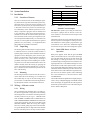
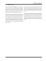
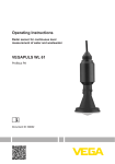
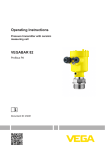
Model 4101-28/5100-28
IR Gas Sensor Module
APPLICABILITY & EFFECTIVITY
This manual provides instructions for the following Sierra Monitor products:
Model
4101-28
5100-28
Description
IR Gas Sensor Module (4-20 mA output)
IR Gas Sensor Module (Sentry bus output)
The instructions are effective for the above models as of October 2002
Instruction Manual Part Number T12013
Rev. B1
Table of Contents
1.0 Description .................................................................................................................................................................
1.1 How It Works .........................................................................................................................................................
1.2 Sensors Poisons and Inhibitors ...............................................................................................................................
2.0 System Installation ........................................................................................................................................................
2.1 Installation ..............................................................................................................................................................
2.1.1
Location of Sensors .................................................................................................................................
2.1.2
Unpacking ................................................................................................................................................
2.1.3
Mounting ..................................................................................................................................................
2.2 Wiring -- 4 - 20 mA version ...................................................................................................................................
2.2.1
Wiring ......................................................................................................................................................
2.2.2
Jumper Location for Non-Isolated / Isolated Current Output ..................................................................
2.2.3
Initial LED Status - 4-20mA Operator .....................................................................................................
2.2.4
Sensor Life ...............................................................................................................................................
2.2.5
Test Jacks .................................................................................................................................................
2.3 Wiring and System Installation - Model 5000 Application ....................................................................................
2.3.1
Wiring ......................................................................................................................................................
3.0 Calibration .................................................................................................................................................................
3.1 Overview ................................................................................................................................................................
3.2 Local Calibration Procedure ..................................................................................................................................
3.3 Start Calibration .....................................................................................................................................................
4.0 Specifications: ...............................................................................................................................................................
5.0 Limited Warranty ..........................................................................................................................................................
Table of Contents
1
1
1
2
2
2
2
2
2
2
2
2
3
3
5
5
6
6
6
6
7
8
Instruction Manual
1.0 Description
The IR Gas Sensor Module utilizes Infrared technology to monitor for combustible gases over the range
of 0-100% LEL. The IR Gas Sensor Module requires
minimal maintenance with a calibration check once a
year. Internal continuous self-diagnostics will automatically indicate any fault or optics problems. The
IR Gas Sensor Module has both digital signal (510028) and a 4-20 mA output signal (4101-28). The digital Sentry bus output signal interfaces directly to Sierra Monitor Sentry System. The 4-20 mA output signal can interface directly to the Sierra Monitor Model
4000 single controller or any standard industrial controller.
Infrared technology has the benefits of:
• Reduced need for calibration and thus lower operating costs.
• Operates in high combustible gas and/or low oxygen environment
• Works in environments where catalytic bead poisons might exist
• Rapid recovery after exposure to high concentra-
tions of hydrocarbon gas (exceeding 100% LEL)
1.1
How It Works
Most combustible gases absorb infrared light energy
at defined wavelengths, providing an absorption signature for that gas. The principle of an infrared detector is based upon the absorption of the infrared light
at a specific wavelength as it passes through the gas.
The more of the absorbing gas that is present, the more
light is absorbed. The detector measures the energy
coming from an infrared light beam at a wavelength
that is absorbed by the combustible gas and compares
it to the energy transmitted by the same. The difference in energy received by the detector indicates the
level of combustible gas in the atmosphere.
1.2 Sensors Poisons and Inhibitors
The IR Gas Sensor Module is not affected by poisons
or inhibitors that may affect Catalytic bead sensors.
3.85”
3.25”
4.35”
C
a
M l/R
O ag es
n n e
S et t
id
e
4.85”
Ca l/Re set
Power Status
STATUS RE D
Slow- Gas
F ast- C al or Fault
Solid- Over ra nge
Model 4101-28
C ALIB R ATION
- Ensur e clean air
- Ho ld reset 10 sec
u ntil solid green
- On fis h’g re d apply
50% spa n gas
- On solid green
rem ove ga s
P ull
- Meter Jack
+ Meter Jack
Co
mb
ustib
4.50”
H ere
C UR RE NT O/P CH ECK
C onne ct curr ent pro bes
to mete r jack s and
r ead mA output
le Gas Co n
r
lle
tro
12.05”
6.75”
2.60”
Fig. 1.0 Outline Dimensions
Page: 1
Model 4101-28/5100-28 IR Gas Sensor Module (7/03)
Instruction Manual
2.0
System Installation
2.1
Installation
2.1.1
Location of Sensors
There are no absolute rules for determining the quantity and location of gas detection heads to protect any
particular facility. Locate the sensors carefully in all
areas where gas escape may be expected and where it
is desirable to detect the presence of unwanted gas.
Use redundancy where enhanced protection or reliability is required. Light gases such as methane tend
to rise while heavy gases such as propane tend to accumulate in low areas. Seek advice from experts who
know the characteristics of the gas being detected, air
movement patterns and the facility. Use common sense
and refer to various publications that discuss general
guidelines for your industry. See Application Data
Sheet ADS-001 for further information.
2.1.2
Unpacking
The housing and terminal board are a single assembly
to which the sensor is wired. The control module is a
separate plug-in assembly. Since all modern electronic
equipment can be damaged by static electricity discharge it is important to take precautions. Discharge
static electricity from your body by touching a
grounded metal object before handling the module.
To gain access to the field terminal block remove the
module carefully from the housing by grasping the
centre “pull” knob and pull straight away. Field wiring is connected to the terminal strip located in the
base of the housing.
2.1.3
Mounting
The housing should be oriented so that the sensor is
on the under-side of the housing. Use a conduit seal
and conduit loop or trap on the field wiring side to
prevent water or condensation from entering the housing through the conduit or its threaded connection.
2.2
Wiring -- 4-20 mA version
2.2.1
Wire Gauge
Maximum Length
16 AWG
2,000 ft.
14 AWG
3,500 ft.
12 AWG
6,000 ft.
10 AWG
9,000 ft.
Recommended Wire / Cable Gauge
Table 1
2.2.2
Jumper Location for Non-Isolated /
Isolated Current Output
The 4101-28 is capable of providing an isolated current output. A jumper must be moved to select between isolated, or non-isolated current output on the
terminal board.
The analog output is precisely controlled by the internal micro-processor and digital-to-analog converter.
The standard 4 to 20ma signal is proportional to gas
concentration of 0 to 100% LEL. Additional stepped
levels below 4mA provide various diagnostic signals.
2.2.3
Initial LED Status - 4-20 mA
Operation
With power applied, check that the green POWER
LED is ON and the FAULT/ CAL LED is showing a
slow red flash during the first 90 seconds which will
then change to a short green flash every 2 seconds
(confidence blip). During the first 90 seconds the analog output will be at 3.0 mA and then change to 4.0mA.
If after the 90 seconds warm-up the current is at 2.5mA
or any value other than 4.0mA then the sensor requires
calibration and the calibration procedure must be initiated. Observation of the LED status signals and output current levels aid the operator when calibrating
the sensor/transmitter as described below under
CALIBRATION.
The module includes an alphanumeric display that provides a variety of English language commands scrolled
across the display to supplement the LED sequences
and aid the operator. Please refer to the following list
and see Table of Responses
Wiring
We recommend using shielded cable. See table below. Refer to applicable wiring codes when installing
and wiring the 4101-28. After the field wiring has been
carefully connected as per Fig 2.1. CHECK THAT
THE CORRECT WIRES ARE CONNECTED TO
THE CORRESPONDING TERMINALS AND THAT
VOLTAGE LEVELS DO NOT EXCEED THE
SPECIFICATIONS. When the wiring and voltages
have been verified, gently plug-in the control module.
Use gentle hand pressure to align and seat the module
then use firm hand pressure to fully seat the module.
Model 4101-28/5100-28 IR Gas Sensor Module (7/03)
Page: 2
Instruction Manual
2.2.4 Sensor Life
Note: The 4101-28's to 20 mA current output must be conSensor life of the module can be expected to exceed 5 nected to a load device in order to facilitate the use of the
test jacks (ie. 100 Ohm resistor must be connected between
years.
the 4 to 20 mA signal output and the common terminal if the
Sensor response may deteriorate very slowly over a pe- unit is being bench tested to field installation).
riod of years, depending on exposure to environmental
factors. If calibration becomes impossible for any reason, the analog output will lock at 2.5mA and the status
START DELAY: power up delay in progress
LED flashes red. Install a new 4101-28 module and remagnetic reed switch is
calibrate. The calibration function automatically adjusts
SWITCH ON:
activated
span amplifier gain across a broad range without any
fault present, sensor or
need for manual adjustment of potentiometers or jumpSENSOR FAULT: sensor wiring table
ers.
calibration zero gas setting
SETTING ZERO:
2.2.5
Test Jacks
The module is equipped with test jacks to facilitate convenient current loop measurements without opening the
external current loop. To make measurements use the
following procedure;
1. Attach the current meter leads to the test jacks located on the face plate.
2. Apply test gas and take meter readings. Set external
controller to Bypass if necessary to avoid unwanted
alarm response.
3. Remove meter leads from test jacks.
CURRENT
OUPUT
(mA)
3
STATUS
Slow Flash
Excess drift (>10%)
2.5
Blip/blink
Auto Zero set
Apply calibration
gas
Span is set, remove
gas
Return to normal
operation
Normal
Gas Present
3
CONDITION
Start-up delay
Page: 3
3.3
in progress
apply 50% of span
APPLY 50%:
calibration gas
span gas detected,
automatic span setting in
SETTING SPAN: progress
GAS:
remove calibration gas
calibration span setting
FAIL CAL:
failed
calibration failed, no gas
TIME-OUT:
detected in calibration
sensor or sensor
SENSOR FAIL:
connections failed
excessive negative sensor
NEG DRIFT:
drift
Table 2: Messages
LED RED LED GREEN
ALPHANUMERIC
STATUS
Start Delay
NEG DRIFT
Solid
Fast Flash
SETTING ZERO
Apply 50% LEL
3.6
Solid
REMOVE GAS
3.6
Solid
CAL COMPLETE
4
Blip/blink
4.4 – 20.0
Blip/Blink
Table 3: LED Status
0.00%
1.0% TO 99% LEL
Model 4101-28/5100-28 IR Gas Sensor Module (7/03)
Instruction Manual
Figure 2.0: Wiring Connections & Settings
Model 4101-28/5100-28 IR Gas Sensor Module (7/03)
Page: 4
Instruction Manual
2.3
Wiring and System Installation - Model
5000 Application
Refer to Sentry Gas Monitoring System, Ver. 6.0 Instruction Manual.
2.3.1 Wiring
Caution: To access the wiring connections on the
5100-28, you will need to remove the enclosure cover
and then remove the cover plate. To remove the cover
plate, pull gently using the knob in the center of the
board.
6. When the wiring , module number, and the voltage
have been verified, gently plug in the control module.
7. The display will show Start delay Model 5100-28
Sierra Monitor.
8. Verify Sentry recognizes the desired module.
9. Calibrate 5100-28 gas sensor module.
1. See Table 1 for wire gauge recommendations.
2. Connect P (1) from Sentry channel to the terminal
at the right hand side which is labelled 24VDC
(position #1).
3. Connect G (3) from Sentry channel to the terminal
at the right hand side which is labelled
COMMON(position #2).
4. Connect S (2) from Sentry channel to the terminal
at the right hand side which is label Sentry (position
# 5).
5. Set the dip switch on each module to indicate the
module number. Each of the modules connected to
one controller must have a different address.
Module
Switch Positions
#
1
2
3
1
ON
ON
ON
2
O FF
ON
ON
3
ON
O FF
ON
4
O FF
O FF
ON
5
ON
ON
O FF
6
O FF
ON
O FF
7
ON
O FF
O FF
8
O FF
O FF
O FF
Note: Switch position 4 is not used
Page: 5
Model 4101-28/5100-28 IR Gas Sensor Module (7/03)
Instruction Manual
3.0
Calibration
3.1
Overview
All applications require an initial calibration upon
power up and before putting the modules into service.
This initial calibration is considered a local calibration, begun and completed at the module. In the Sentry applications, the initial local calibration is to be
followed up with a global calibration at the controller. (See Chapter 5 in the Sentry manual, T121001).
In the 4-20mA applications a system calibration undertake at the control device may be necessary.
10. When the concentration of calibration gas falls to approximately 12% LEL the module will come out of the
calibration mode and be in normal operation.
11. The status LED will return to its normal pulse rate.
12. Perform a system calibration.
13. Follow chapter 5 in the Sentry manual or follow the owners manual of the control device.
During the local calibration, the module output is
clamped to prevent the control devices from interpreting the calibration gas as an alarm even.
System response should be checked every 6-9 months
and the modules should be recalibrated as necessary
or at least every year.
3.2
Local Calibration Procedure
You will need the following items to
complete calibration:
• 1260-01: Cylinder of Air if none concentration of
gas in background is greater than zero
• 1260-02: Cylinder of 50% LEL Methane balance
air or 1256-28: Cylinder of 50% LEL Propane balance air.
• 1256-04: 2LPM flow Regulator.
• 1255-02: Gas Calibration Tubing, PTFE or equal
1/4 OD
• 1250-04: Calibration Kit is a case for storage of 2
cylinders and contains the tubing and regulator
3.3
Start Calibration
1. Deliver air if necessary for 2 minutes at 2LPM.
Remove at step noted below.
2. Place and hold curved side of the magnet attached
to the module at the 10:00 position on the module
to commence calibration. The display will indicate
the "Switch is on" followed by "Setting Zero". The
status LEDs goes from slow pulsing green to steady
green.
3. Remove magnet.
4. Remove air.
5. The status LED will go green indicating span gas
may be applied.
6. Follow the prompts on the display;
7. Deliver calibration gas for 3 minutes at 2LPM.
8. Remove the gas after 3 minutes or when
prompted.
9. The status LED will go to green indication calibration was successful.
Model 4101-28/5100-28 IR Gas Sensor Module (7/03)
Page:
6
Instruction Manual
Construction:
5100-28 Sentry Display Bus
13.5 x 4.75 x 4.2 inches
(34.3 x 12.1 x 10.7 cm)
5 lb. (2.2 Kg)
Explosion proof,
Class 1, Div. I, Groups B,
C, D
CSA Class 1, DIN I,
Groups B, C, D NRTL/C
Appovals
2 years
Warranty:
(Specifications subject to change without notice)
Dimensions:
(HxWxD)
Weight:
Housing:
4.0
Specifications:
Sensor type:
Infrared
Performance
Range:
Repeatability:
Linearity:
Zero Drift:
Response time:
Accuracy:
Sensor Life:
0-100% LEL methane or
propane (Other Hydrocarbons
on request)
+/-2% LEL
+/- 3% LEL
< 1% per month
30 sec to 90% Full Scale
+ 3% LEL up to 50% LEL,
+ 5% LEL above 50% LEL
Typically >5 years (for use at
standard temperature &
pressure)
Operating Range:
Ambient Temperature
-40o to 167oF (-40o to 75oC)
Range:
5-99%
Relative Humidity:
Electrical Data:
Power consumption: 3.0 watts nominal, 5.0 watts
maximum
3 wire
Loop type:
800 Ohms @
Loop resistance:
Page:
7
Model 4101-28/5100-28 IR Gas Sensor Module (7/03)
Instruction Manual
5.0
Limited Warranty
SIERRA MONITOR CORPORATION warrants its products
to be free from defects in workmanship or material under
normal use and service for two years after date of shipment.
SMC will repair or replace without charge any equipment
found to be defective during the warranty period. Final determination of the nature and responsibility for defective or
damaged equipment will be made by SMC personnel.
All warranties hereunder are contingent upon proper use in
the application for which the product was intended and do
not cover products which have been modified or repaired
without SMC approval or which have been subjected to accident, improper maintenance, installation or application, or
on which original identification marks have been removed
or altered. This Limited Warranty also will not apply to interconnecting cables or wires, consumables (ie. calibration
gases, batteries, sensors), nor to any damage resulting from
battery leakage.
Model 4101-28/5100-28 IR Gas Sensor Module (7/03)
In all cases SMC’s responsibility and liability under this warranty shall be limited to the cost of the equipment. The purchaser must obtain shipping instructions for the prepaid return of any item under this warranty provision and compliance with such instruction shall be a condition of this warranty.
Except for the express warranty stated above, SMC disclaims
all warranties with regard to the products sold hereunder including all implied warranties of merchantability and fitness
and the express warranties stated herein are in lieu of all obligations or liabilities on the part of SMC for damages including, but not limited to, consequential damages arising
out of/or in connection with the use or performance of the
product.
Page: 8