1
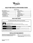
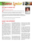
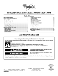
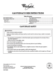
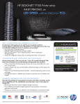
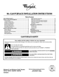
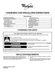
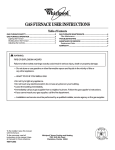
NATURAL GAS TO PROPANE CONVERSION KIT
ALPKT572-2 INSTALLATION INSTRUCTIONS
Table of Contents
PROPANE CONVERSION KIT SAFETY........................................1
INSTALLATION REQUIREMENTS ................................................2
Tools and Parts ............................................................................2
LP Gas Requirements ..................................................................2
INSTALLATION INSTRUCTIONS ..................................................3
Remove Low NOx Inserts ............................................................3
Convert Furnace...........................................................................4
Make Gas Connections..............................................................10
Check the Furnace Input Rate ...................................................10
Adjust the Furnace Input Rate ...................................................11
Complete Installation..................................................................12
PROPANE CONVERSION KIT SAFETY
Your safety and the safety of others are very important.
We have provided many important safety messages in this manual and on your appliance. Always read and obey all
safety messages.
This is the safety alert symbol.
This symbol alerts you to potential hazards that can kill or hurt you and others.
All safety messages will follow the safety alert symbol and either the word “DANGER” or
“WARNING.” These words mean:
You can be killed or seriously injured if you don't
immediately follow instructions.
You can be killed or seriously injured if you don't
follow instructions.
All safety messages will tell you what the potential hazard is, tell you how to reduce the chance of injury, and tell you
what can happen if the instructions are not followed.
WARNING
This conversion kit shall be installed by a qualified service agency in accordance with the manufacturer’s instructions and
all applicable codes and requirements of the authority having jurisdiction. If the information in these instructions is not
followed exactly, a fire, explosion, or production of carbon monoxide may result, causing property damage, personal
injury, or loss of life. The qualified service agency is responsible for the proper installation of this kit. The installation is not
proper and complete until the operation of the converted appliance is checked as specified in the manufacturer’s
instructions supplied with the kit.
Models
45900D003
WFAR, WFAT, WFAU, WFCH, WFCU, WFLR, WFLU, WFLT
G1N80AR, G1N80AT, G1N80AU,
G1D80AR, G1D80AT, G1D90AH, G1D91AU,
CG80RA, CG80TA, CG80UA, CG90HA, CG90UA
Caution:
The gas supply shall be shut off prior to disconnecting the electrical power, before proceeding with the conversion.
For Canadian Conversions:
The conversion shall be carried out by a manufacturer’s authorized representative, in accordance with the
requirements of the manufacturer, provincial, or territorial authorities having jurisdiction and in accordance with the
requirements of Canadian Installation Codes CAN/CGA-B149.1 & B149.2.
ADDITIONAL SAFETY INFORMATION
In the State of Massachusetts, the following installation instructions apply:
■
■
■
Installations and repairs must be performed by a qualified or licensed contractor, plumber, or gasfitter qualified or
licensed by the State of Massachusetts.
If using a ball valve, it shall be a T-handle type.
A flexible gas connector, when used, must not exceed 3 feet.
INSTALLATION REQUIREMENTS
These instructions are intended as a general guide only and do
not supersede any national or local codes in any way.
Compliance with all local, state or national codes pertaining to
this type of equipment should be determined prior to installation.
Read this entire instruction manual as well as instructions
supplied with separate equipment before starting the installation.
This kit contains parts and instructions for converting furnaces
from natural gas to propane. In these instructions, LP is an
abbreviation for propane.
Depending on the specific model being converted, all of the parts
in the kit may not be required. Refer to the appropriate section in
these instructions to convert your particular furnace model type.
The model types covered in this instruction guide include: Open
Burner Box, Closed Burner Box and Horizontal.
IMPORTANT: It is recommended that the conversion from
natural gas to propane is completed prior to making final gas
connections.
Tools and Parts
Check that you have everything necessary for correct installation.
Proper installation is your responsibility.
Assemble the required tools before starting installation. Read and
follow the instructions provided with any tools listed here.
Tools Needed:
■
Screwdriver
■
Pipe wrench
■
Allen wrench
■
Adjustable wrench
■
Thread sealant
■
Non-corrosive leak check solution
■
¹⁄₄ in. Nut driver
■
Test gauge with ¹⁄₈ in. NPT
connection
(for measuring gas supply pressure)
2
Parts Supplied:
■
Self-drilling, self-tapping
screws (2)
■
Conversion plate label
■
#54 Size orifices (6)
■
Gas control valve
conversion label
■
Conversion kit for Gas
Control Valve
■
Gas conversion manifold
label.
■
3 in. x 6 in. Steel LP
adapter plates (2)
■
Furnace conversion
information label
■
3 in. x 9 in. Steel LP
adapter plates (2)
Parts Needed:
Read “LP Gas Requirements” and check local codes and
ordinances before purchasing parts.
LP Gas Requirements
The furnace has a regulator in the gas control valve. A regulator is
also required on the propane tank. Another regulator is required
at the house or unit.
The minimum LP gas pressure required at the furnace
is 11 in. W.C.
The maximum LP Gas pressure allowed at the furnace
is 13 in. W.C.
INSTALLATION INSTRUCTIONS
4. Disconnect 2 wire connections at the high limit switch.
\
3
1
4
2
Explosion Hazard
Furnace must be installed and serviced by a
qualified person.
Examples of a qualified person include:
licensed heating personnel,
authorized gas company personnel.
Read and follow all instructions provided for
installation, adjustment, service, alteration, or
maintenance.
Failure to follow these instructions can result in death,
explosion, fire, or carbon monoxide poisoning.
1. Pressure switch
2. Wire connections
3. High limit switch
4. Wire connections
5. Remove the 6 screws attaching the burner box to the panel.
First remove the 2 screws from each side, then remove the 2
screws from the top of the burner box.
Remove Low NOx Inserts
(on some models)
This section refers only to models that contain an “L” in the full
model number. If your model does not have an “L” in the full
model number, please go to “Convert Furnace” section now.
IMPORTANT: The low NOx inserts must be removed from these
models before converting the furnace from natural gas to LP Gas.
4
1
5
2
2
2
WARNING
3
Electrical Shock Hazard
Disconnect power before servicing.
Replace all parts and panels before operating.
Failure to do so can result in death or electrical shock.
1. Pressure switch
2. Screws (to remove)
3. Burner box
4. High limit switch
5. Panel
6. Remove the burner box.
1. Disconnect power.
2. Remove the burner door.
3. Disconnect 2 wire connections at the pressure switch.
3
7. Remove the screws fastening the low NOx inserts to the
panel. The tabs attached to the low NOx inserts will remain
on the inserts.
3
1
2
4
4
8. Slide the low NOx inserts from the heat exchangers and
discard. Repeat this removal process for all burners.
9. Replace the screws that secured the low NOx inserts into
their previous holes. This will help maintain the correct air
mixture to the furnace.
10. Using the 6 screws removed in step 5, reattach the burner
box to the panel. First replace the 2 top screws, then replace
the 2 screws on each side.
11. Reconnect the 2 wire connections to the high limit switch,
and the 2 wire connections to the pressure switch.
12. Replace the burner door.
5
1. Pressure switch
2. Screws (holding low NOx inserts)
3. High limit switch
4. Tabs attached to
low NOx inserts
5. Low NOx insert
Convert Furnace
Furnace Type
Determine the type of burner configuration that is provided on
your furnace and follow the instructions for that type.
The 3 types of burner configurations are:
■ Open burner box
■
Closed burner box
■
Horizontal burner box
Open Burner Box Furnace Conversion
IMPORTANT: This section refers only to models: WFAR, WFAT, WFAU, WFLR, WFLU, WFLT, GIN80AR, GIN80AT, GIN80AU, CG80RA,
CG80TA, and CG80UA.
5. Remove the manifold from the burner box by removing the 4
mounting screws.
WARNING
Electrical Shock Hazard
Disconnect power before servicing.
1
Replace all parts and panels before operating.
Failure to do so can result in death or electrical shock.
2
1.
2.
3.
4.
2
Turn off gas supply at manual gas shutoff valve.
Disconnect power.
Remove the burner access door.
Disconnect all wires from gas control valve.
1. Manifold
2. Mounting screws
4
6. Remove the regulator adjustment cap with “O” ring, pressure
regulator adjusting screw, and spring from the gas control
valve. See “Gas Control Valve” graphic.
OFF
ON
1
2
3
C3
C1
C2
Gas Control Valve
11. Determine which LP gas adapter plate(s) are needed for the
furnace being converted by referring to the “LP Adapter Plate
Configuration Chart”.
NOTE: Steel LP gas adapter plates are used singly or in
combinations of A and/or B.
1
A
2
B
4
5
6
1. 3 in. x 6 in.
2. 3 in. x 9 in.
1
7
8
LP Adapter Plate Configuration Chart
Rated Gas Input (Btu/Hr)
Plate(s) Used
50,000
A Plate
75,000
B Plate
100,000
(2) A Plates
125,000
A Plate + B Plate
150,000
(2) B Plates
9
If the installation calls for 2 plates, mount the 2 plates side by
side on the bottom rail of the burner rack.
1. Regulator adjustment cap
2. Inlet pressure tap
3. Gas inlet
4. Outlet pressure tap
5. Gas outlet
6. Gas control switch
7. “O” ring
8. Pressure regulator adjusting screw
9. Spring
12. Install the adapter plate(s) as shown. The plates mount onto
the bottom rail of the burner rack. Slide the plate forward until
the lip of the plate is against the vertical surface of the burner
rack. Attach the adapter plate(s) to the burner rack using the
self-drilling, self-tapping screw(s) supplied with the kit. If the
installation calls for 2 plates, mount the plates side by side on
the bottom rail of the burner rack.
1
7. Convert the Gas Control Valve for LP Gas.
■ Open the plastic bag included in this kit.
■
Locate the new spring (different color) and install.
■
Locate the new pressure regulator adjusting screw and
thread in such a way that the top of the regulator
adjusting screw is flush with the surface of the gas control
valve.
■
Turn regulator adjusting screw clockwise 11 full turns.
■
Install new “O” ring into new regulator adjustment cap
(BLACK).
■
Install the new regulator adjustment cap (BLACK).
■
Affix the gas control valve conversion label included in the
plastic bag to the top of the gas control valve.
8. Remove the orifices from the manifold. Thread in the new LP
Gas orifices located in the kit.
9. Reinstall the manifold to the burner box using the 4 screws
removed earlier.
10. Affix the gas conversion manifold label “This control has been
converted for use with propane gas” to the manifold in a
visible location.
2
3
4
1. Burners
2. Burner rack
3. Bottom rail
4. Steel LP adapter plate
13. Reconnect all wires to gas control valve.
14. Fill in the required information on the Furnace Conversion
Information Label.
15. Affix the Furnace Conversion Information Label in a visible
location adjacent to the furnace.
16. Affix the Conversion Plate Label as close as possible to the
existing rating plate without covering the rating plate.
17. Dispose of all remaining parts.
18. Go to the “Make Gas Connections” section.
5
Closed Burner Box Furnace Conversion
IMPORTANT: This section refers only to models WFCU, GID80AR, GID80AT, GID91AU, and CG90UA.
7. Remove the manifold from the burner box by removing the 4
mounting screws.
WARNING
Electrical Shock Hazard
Disconnect power before servicing.
Replace all parts and panels before operating.
1
Failure to do so can result in death or electrical shock.
1.
2.
3.
4.
5.
2
2
Turn off gas supply at manual gas shutoff valve.
Disconnect power.
Remove the burner access door.
Disconnect all wires from gas control valve.
Remove the burner box cover and gasket from the burner
box by removing the 4 mounting screws.
1. Manifold
2. Mounting screws
8. Remove the regulator adjustment cap with “O” ring, pressure
regulator adjusting screw, and spring from the gas valve. See
“Gas Control Valve.”
1
2
OFF
ON
1
2
3
C1
2
C3
C2
Gas Control Valve
4
5
6
1. Burner box cover
2. Mounting screws
1
6. Remove flexible tubing from the burner box and the gas
control valve.
7
8
9
1. Regulator adjustment cap
2. Inlet pressure tap
3. Gas inlet
4. Outlet pressure tap
5. Gas outlet
6
6. Gas control switch
7. “O” ring
8. Pressure regulator adjusting screw
9. Spring
9. Convert the Gas Control Valve for LP Gas.
■ Open the plastic bag included in this kit.
■
Locate the new spring (different color) and install.
■
Locate the new pressure regulator adjusting screw and
thread in such a way that the top of the regulator
adjusting screw is flush with the surface of the gas control
valve.
■
Turn regulator adjusting screw clockwise 11 full turns.
■
Install new “O” ring into new regulator adjustment cap
(BLACK).
■
Install the new regulator adjustment cap (BLACK).
■
Affix the gas control valve conversion label included in the
plastic bag to the top of the gas control valve.
10. Remove the orifices from the manifold. Thread in the new LP
Gas orifices located in the kit.
11. Reinstall the manifold to the burner assembly using the 4
screws removed earlier.
12. Affix the Gas Conversion Manifold Label “This control has
been converted for use with propane gas” to the manifold in a
visible location.
13. Determine which LP gas adapter plate(s) are needed for the
furnace being converted by referring to the “LP Adapter Plate
Configuration Chart.”
NOTE: Steel LP gas adapter plates are used singly or in
combinations of A and/or B.
1
A
2
B
1. 3 in. x 6 in.
2. 3 in. x 9 in.
LP Adapter Plate Configuration Chart1
Rated Gas Input (Btu/Hr)
Plate(s) Used
50,000
A Plate
75,000
B Plate
100,000
(2) A Plates
125,000
A Plate + B Plate
150,000
(2) B Plates
14. Install the adapter plate(s) as shown. The plates mount onto
the bottom rail of the burner rack. Slide the plate forward until
the lip of the plate is against the vertical surface of the burner
rack. Attach the adapter plate(s) to the burner rack using the
self-drilling, self-tapping screw(s) supplied with the kit. If the
installation calls for 2 plates, mount the plates side by side on
the bottom rail of the burner rack.
1
2
3
4
1. Burners
2. Burner rack
3. Bottom rail
4. Steel LP adapter plate
15. Reinstall the burner box cover and gasket using the 4 screws
removed earlier.
16. Reconnect all wires to gas control valve.
17. Replace the flexible tubing to the burner box and the gas
control valve. Ensure that there are no kinks in the tubing.
18. Fill in the required information on the Furnace Conversion
Information Label.
19. Affix the Furnace Conversion Information Label in a visible
location adjacent to the furnace.
20. Affix the Conversion Plate Label as close as possible to the
existing rating plate without covering the rating plate.
21. Dispose of all remaining parts.
22. Go to the “Make Gas Connections” section.
If the installation calls for 2 plates, mount the 2 plates side by
side on the bottom rail of the burner rack.
1
The LP adapter plates are not required for models WFCU,
CG90UA, and G1D91AU.
7
Horizontal Furnace Conversion
IMPORTANT: This section refers only to models WFCH, CG90HA, and GID90AH. LP adapter plates are not required for these models.
8. Remove the burner locking tab from the burner box by
removing the 2 screws. Note that the flange faces inward.
WARNING
1
2
Electrical Shock Hazard
Disconnect power before servicing.
Replace all parts and panels before operating.
Failure to do so can result in death or electrical shock.
1.
2.
3.
4.
Turn off gas supply at manual gas shutoff valve.
Disconnect power.
Disconnect all wires from gas control valve.
Disconnect 2 leads to the rollout switch behind the gas
control valve.
5. Remove flexible tubing from the burner box and the gas
control valve.
6. Remove the manifold plate (2 screws) from the furnace and
the manifold grommet.
1. Burner locking tab
2. Locking tab flange
9. Remove the burner assembly by moving the manifold
support bracket off the 4 alignment screws. The alignment
screws serve as a track or guide to align the burner assembly.
There are 2 alignment screws at each end of the burner
assembly compartment. Pull the whole assembly straight out
of the compartment.
1
2
3
4
5
6
4
2
1
1. Burner access plate
2. Clearance holes
3. Rollout switch
4. Manifold plate screws
5. Manifold grommet
6. Manifold plate
7. Remove the remaining 6 screws attaching the burner access
plate to the unit. Leave the screws located in the 2 clearance
holes. Remove the burner access plate.
8
2
1. Burner locking tab
2. Manifold support brackets
10. Remove the regulator adjustment cap with “O” ring, pressure
regulator adjusting screw, and spring from the gas control
valve. See “Gas Control Valve” graphic.
C3
C2
Gas Control Valve
14. Affix the Gas Conversion Manifold Label “This control has
been converted for use with propane gas” to the manifold in a
visible location.
IMPORTANT: When reassembling the manifold, make sure that
no electrical wiring gets pinched. Ensure that the burner igniter is
aligned properly with the burner. The burner igniter tube should
be perpendicular to the burner, not askew.
OFF
ON
C1
1
1
2
3
4
5
2
1
6
2
1
7
8
9
1. Regulator adjustment cap
2. Inlet pressure tap
3. Gas inlet
4. Outlet pressure tap
5. Gas outlet
6. Gas control switch
7. “O” ring
8. Pressure regulator adjusting screw
9. Spring
11. Convert the Gas Control Valve for LP Gas.
■ Open the plastic bag included in this kit.
■
Locate the new spring (different color) and install.
■
Locate the new pressure regulator adjusting screw and
thread in such that the top of the regulator adjusting
screw is flush with the surface of the gas control valve.
■
Turn regulator adjusting screw clockwise 11 full turns.
■
Install new “O” ring into new regulator adjustment cap
(BLACK).
■
Install the new regulator adjustment cap (BLACK).
■
Affix the gas control valve conversion label included in the
plastic bag to the top of the gas control valve.
12. Remove the manifold from the burners by removing the 2
screws on each side of the burner.
13. Remove the orifices from the manifold. Thread in the new LP
Gas orifices located in the kit.
1. Burner igniter tube
2. Burner throat
15. Replace the manifold on the burners using the 2 screws (one
on each side of the burner) removed earlier.
16. Reassemble the burner assembly to the furnace. Align the
slots in the burner assembly end plates with the alignment
screws on both ends of the burner assembly compartment
(reassembly can be made easier by removing the burner
access panel on the opposite side of the furnace to be able to
see the alignment screws on this side of the manifold
assembly).
17. Replace the burner locking tab with flange facing inward (2
screws).
18. Replace the burner access plate (6 screws). Make sure that
the slot in the plate is positioned into the slot in the manifold
grommet.
19. Replace the manifold plate (2 screws). Make sure that the slot
in the plate is positioned into the slot in the manifold
grommet.
20. Replace the flexible tubing to the burner box and gas control
valve. Ensure there are no kinks in the tubing.
21. Reconnect 2 leads to the rollout switch behind the gas
control valve.
22. Reconnect all wires to the gas control valve.
23. If the burner access plate was removed, check to see if you
have reinstalled the burner access plate on the opposite side
of the furnace (8 screws).
24. Fill in the required information on the Furnace Conversion
Information label.
25. Affix the Furnace Conversion Information Label in a visible
location adjacent to the furnace without covering the rating
plate.
26. Affix the Conversion Plate Label as close as possible to the
existing rating plate.
27. Dispose of all remaining parts.
28. Go to the “Make Gas Connections” section.
9
Make Gas Connections
1. Install the field gas supply as shown.
2. Provide a sediment trap on the outside of the furnace.
3. Install a manual gas shutoff valve in the gas line, outside the
unit, 5 ft above the floor, or in accordance with any local
codes.
4. Install a test gauge connection with a ¹⁄₈ in. NPT plugged
tapping immediately upstream of the manual gas shutoff
valve as shown.
5. Connect the gas pipe to the furnace controls providing a
ground joint union as close to the controls as possible to
facilitate removal of controls and manifold.
Pipe-joint compounds suitable for use with natural and LP
gas must be used. Do not use Teflon® tape.
1
2
3
4
The maximum inlet gas supply pressure is 10.5 in. W.C. for
natural gas and 13 in. W.C. for propane gas.
10. Turn off the gas supply at the manual gas shutoff valve.
IMPORTANT: If the inlet gas supply pressure is not within the
minimum and maximum range as shown on the rating plate,
contact your gas supplier.
11. Disconnect the pressure gauge from the ¹⁄₈ in. NPT inlet
pressure tap.
12. Replace the inlet pressure tap plug on the gas control valve.
13. Turn on the gas supply at the manual gas shutoff valve.
14. Test all connections by brushing on an approved noncorrosive leak-detection solution. Bubbles will show a leak.
Correct any leak found.
■ At test pressures greater than ¹⁄₂ psig (3.5 kPa), the
furnace and the manual gas shutoff valve must be
disconnected from the gas supply piping system.
■
5
6
7
At test pressures less than or equal to ¹⁄₂ psig (3.5 kPa),
the furnace must be isolated from the gas supply piping
system by closing the manual gas shutoff valve.
15. Replace the burner access door.
1. ¹⁄₈ in. NPT plugged tapping
2. Manual gas shutoff valve
3. Ground joint union
4. Tee
5. Sediment trap
6. Cap
7. Gas control valve
(inside furnace)
WARNING
FIRE OR EXPLOSION HAZARD
Failure to follow the safety warnings exactly could result
in serious injury, death or property damage.
Never test for gas leaks with an open flame. Use a
commercially available soap solution made specifically
for the detection of leaks to check all connections. A fire
or explosion may result causing property damage,
personal injury or loss of life.
6. Turn off the gas supply at the manual gas shutoff valve.
1. Closed valve
2. Open valve
®Teflon is a registered trademark of E.I. Dupont de Nemours and
Company.
10
7. Remove the inlet pressure tap plug on the gas control valve
and connect pressure gauge to the ¹⁄₈ in. NPT inlet
pressure tap.
8. Turn on the gas supply at the manual gas shutoff valve.
9. Observe the inlet pressure.
The minimum inlet gas supply pressure is 5 in. W.C. for
natural gas and 11 in. W.C. for propane gas.
Check the Furnace Input Rate
(if required)
BTU ratings shown on the furnace rating plate are for elevations
up to 2,000 ft (USA and Canada). In the USA, for elevations
above 2,000 ft, the ratings should be reduced at the rate of 4%
for each 1,000 ft above sea level. In Canada, follow the altitude
rating label on the furnace for elevations of 2,000 to 4,500 ft;
above 4,500 ft, the ratings should be reduced an additional 4%
for each additional 1,000 ft.
IMPORTANT:
■ The furnace input rate must not exceed the input rating on
the furnace rating plate.
■
At altitudes from 2,000 to 7,500 ft the furnace input rate must
not exceed that on the rating plate multiplied by the Input
Factor in the Manifold Pressure vs. Altitude chart.
■
This furnace is equipped for rated input at manifold pressure
of 10.0 in. W.C. for propane gas.
■
The actual heating value of your propane gas can be obtained
from your local gas supplier.
Adjust the Furnace Input Rate
(if required)
IMPORTANT: Follow these instructions for the altitude of your
installation.
■ Above 10,000 ft: Furnace is not recommended for
installations above 10,000 ft.
■
7,500 to 10,000 ft:
–
■
■
The orifices in this kit must be replaced. For the correct
orifice size, see Table F.4 in Appendix F of the National
Fuel Gas Code (ANSI Z223.1/NFPA 54, latest edition).
– Do not adjust manifold pressure. The furnace input rate is
to be reduced per the requirements of the National Fuel
Gas Code (ANSI Z223.1/NFPA 54, latest edition).
4,500 to 7,500 ft: Adjust the manifold pressure according to
the information in the “Manifold Pressure vs. Altitude” chart.
0 to 4,500 ft: Adjust the manifold pressure to 10.0 in. W.C. for
propane gas.
To Adjust Manifold Pressure
6. Turn on the electrical power to the furnace.
7. Set the room thermostat to a point above room temperature
to light the main burners.
8. Observe the pressure reading on the pressure gauge.
9. Refer to the Manifold Pressure vs. Altitude chart for the
correct manifold pressure. If necessary, remove the regulator
adjusting cap on the gas control valve and turn the regulator
adjusting screw clockwise to increase pressure and input, or
counterclockwise to decrease pressure and input.
IMPORTANT: If the manifold pressure cannot be adjusted to
the correct value, contact your gas supplier.
10. Move the gas control switch to the OFF position.
11. Disconnect the pressure gauge from the 1/8 in. NPT outlet
pressure tap.
12. Replace outlet pressure tap plug and the regulator adjusting
cap on the gas valve.
13. Move the gas control switch to the ON position.
14. Replace the burner access door.
15. Set the room thermostat to the desired temperature
necessary to achieve optimum temperature rise.
Manifold Pressure vs. Altitude Chart
1. Remove the burner access door.
2. Move the gas control switch to the OFF position. Use only our
hand to move the gas control switch; tools are not required.
3. Remove the outlet pressure tap plug on the gas valve and
connect pressure gauge to the ¹/8 in. NPT outlet pressure tap.
Propane Gas
Altitude (ft)
Heating Value
(BTU/ft3)
Manifold
Pressure (in.
W.C.)
Input
Factor
2000
2278
10.00
0.9666
3000
2196
10.00
0.9499
4000
2116
10.00
0.9332
4500
2077
10.00
0.9249
5000
2039
9.41
0.8900
5500
2000
9.35
0.8790
1. ¹⁄₈ ” NPT Inlet pressure tap
2. Regulator adjusting cap
3. Diagnostic LED
4. ¹⁄₈ ” NPT Outlet pressure tap
5. Gas control switch
6000
1964
9.29
0.8680
6500
1927
9.24
0.8570
7000
1891
9.18
0.8460
4. Be sure the gas control switch has been in the OFF position
or at least 5 minutes before starting the unit.
5. Move the gas control switch to the ON position.
NOTE: This furnace is equipped with an ignition device which
automatically lights the burner. This furnace cannot be lighted
manually. Do not try to light the burner by hand.
7500
1853
9.12
0.8350
Gas Control Valve
C3
C2
3
2
1
C1
1/2" NPT Inlet
OFF
ON
4
1/2" NPT Outlet
5
11
Adjust Blower Speed
Complete Installation
IMPORTANT: Do not use this furnace if any part has been under
water. Immediately call a qualified person to inspect the furnace
and to replace any part of the control system and gas control
which has been under water.
1. Check to be sure you have all of your tools.
2. Dispose of all packaging materials.
3. Check the furnace in its final location. Be sure the vent is not
blocked.
WARNING
Electrical Shock Hazard
Measure Temperature Rise
Disconnect power before servicing.
1. After 20 minutes of heating operation, measure the furnace
temperature rise. Take air temperature readings in both the
return air ducts and the heated air ducts (about 6 ft from the
furnace where they will not be affected by radiant heat) as
shown.
NOTE: If more than one run of return or heated air ducts is
used, air temperature measurements should be taken in each
duct. These measurements can be converted to an average
to obtain the temperature rise of the whole system.
Warm Air
2
1
Replace all parts and panels before operating.
Failure to do so can result in death or electrical shock.
NOTE: See the Wiring Diagram, in your Furnace Installation
Instructions, for the model you are installing while performing this
procedure.
To increase temperature rise:
1. Disconnect power.
2. Remove control box cover.
3. The furnace is factory configured for medium speed (blue
wire) for heating. Connect a lower speed wire (Med/Lo or Lo)
to the Heat terminal.
4. Replace control box cover.
5. Recheck the temperature rise. If the temperature rise cannot
be adjusted within the limits as listed on the furnace rating
plate, see your Furnace Installation Instructions for
troubleshooting information.
To decrease temperature rise:
Return Air
1. Measure return air here.
2. Measure supply temperature here.
2. If furnace doesn't maintain temperature rise within the range
shown on the furnace rating plate, adjust the blower speed.
1. Disconnect power.
2. Remove control box cover.
3. The furnace is factory configured for medium speed (blue
wire) for heating. Remove the blue wire from the Heat terminal
and place it at M1 or M2 on the blower control board.
4. Connect a higher blower speed wire (Med/Hi or High) to the
Heat terminal.
5. Replace control box cover.
6. Recheck the temperature rise. If the temperature rise cannot
be adjusted within the limits as listed on the furnace rating
plate, see your Furnace Installation Instructions for
troubleshooting information.
NOTE: If low speed (LO) is required for proper temperature rise,
the continuous fan feature should not be used.
Shut Down the Furnace
1.
2.
3.
4.
Set the room thermostat to the lowest setting.
Disconnect power.
Remove burner access door.
Shut off the gas by moving the gas control switch to the OFF
position.
5. Replace the burner access door.
See your Furnace Installation Instructions for troubleshooting
information.
45900D003
© 2003. All rights reserved.
5/03
Printed in U.S.A.