1
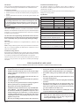
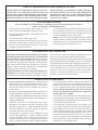
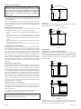
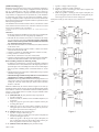
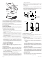
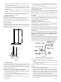
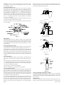
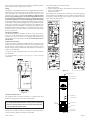
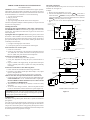
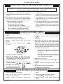
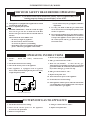
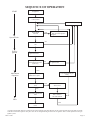
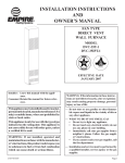
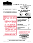
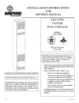
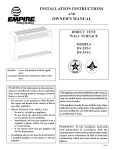
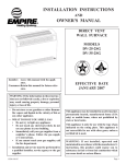
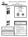
INSTALLATION INSTRUCTIONS AND OWNER'S MANUAL FAN TYPE VENTED WALL FURNACE MODEL FAW-40-1SPP FAW-40-1IP WARNING: If the information in these instructions are not followed exactly, a fire or explosion may result causing property damage, personal injury or loss of life. — Do not store or use gasoline or other flammable vapors and liquids in the vicinity of this or any other appliance. Installer: Leave this manual with the appliance. Consumer: Retain this manual for future reference. WARNING: If not installed, operated and maintained in accordance with the manufacturer's instructions, this product could expose you to substances in fuel or from fuel combustion which can cause death or serious illness. — WHAT TO DO IF YOU SMELL GAS • Do not try to light any appliance. • Do not touch any electrical switch; do not use any phone in your building. • Immediately call your gas supplier from a neighbor’s phone. Follow the gas supplier’s instructions. • If you cannot reach your gas supplier, call the fire department. — Installation and service must be performed by a qualified installer, service agency or the gas supplier. Page 1 Introduction Always consult your local Building Department regarding regulations, codes or ordinances which apply to the installation of a vented wall furnace. Instructions to Installer 1. Installer must leave instruction manual with owner after installation. 2. Installer must have owner fill out and mail warranty card supplied with furnace. 3. Installer should show owner how to start and operate furnace and thermostat. Warning: Any change to this furnace or its control can be dangerous. This is a heating appliance and any panel, door or guard removed for servicing an appliance must be replaced prior to operating the appliance. General Information This series is design certified in accordance with American National Standard / CSA Standard Z21.86 and CSA 2.32 by the Canadian Standards Association, as a Fan Type Vented Wall Furnace and must be installed according to these instructions. Any alteration of the original design, installed other than as shown in these instructions or use with a type of gas not shown on the rating plate is the responsibility of the person and company making the change. Important All correspondence should refer to complete Model No., Serial No. and type of gas. Notice: During initial firing of this unit, its paint will bake out and smoke will occur. To prevent triggering of smoke alarms, ventilate the room in which the unit is installed. Installation in Residential Garages Gas utilization equipment in residential garages shall be installed so that all burners and burner ignition devices are located not less than 18" (457mm) above the floor. Such equipment shall be located, or protected, so it is not subject to physical damage by a moving vehicle. Specifications Model FAW-40SPP FAW-40IP Input BTU/HR (KW/H) 40,000 (11.7) 40,000 (11.7) Height 72 1/2" (84.1mm) 72 1/2" (184.1mm) Width 14 1/8" (35.9mm) 14 1/8" (35.9mm) Depth 10 3/8" (26.4mm) 10 3/8" (26.4mm) Gas Inlet Pipe 1/2" (12.7mm) 1/2" (12.7mm) Vent Collar Type B Oval 4" (101mm) 4" (101mm) CFM 275 275 Accessories SOR-1 Register, side outlet, fixed register Side outlet, 10" (254mm) SOK-1 maximum extension, fixed register Rear outlet, 10" (254mm) ROK-1 maximum extension, adjustable register FVE-24 Vent enclosure, 24" (609mm) [for rooms up to 96 1/2" 2451mm) in height] Vent enclosure, 34" (86cm) FVE-34 [for rooms up to 106 1/2" (2705mm) in height] Vent enclosure, 46" (1168mm) FVE-46 [for rooms up to 118 1/2" (3009mm) in height] Oval-to-Round flue adapter kit 4" (102mm) DV-648 Installation on Rugs and Tile If this appliance is installed directly on carpeting, tile or other combustible material other than wood flooring the appliance shall be installed on a metal or wood panel extending the full width and depth of the appliance. The base referred to above does not mean the fire-proof base as used on wood stoves. The protection is for rugs that are extremely thick and light colored tile. THIS IS A HEATING APPLIANCE DO NOT OPERATE THIS APPLIANCE WITHOUT FRONT PANELS INSTALLED. • Due to high temperatures the appliance should be located out of traffic and away from furniture and draperies. • Children and adults should be alerted to the hazards of high surface temperatures and should stay away to avoid burns or clothing ignition. • Young children should be carefully supervised when they are in the same room as the appliance. • Clothing or other flammable material should not be placed on or near the appliance. • Any safety screen or guard removed for servicing an appliance must be replaced prior to operating the appliance. • Keep burner and control compartment clean. • Installation and repair should be done by a QUALIFIED SERVICE PERSON. The appliance should be inspected before use and at least annually by a qualified service person. More frequent cleaning may be required due to excessive lint from carpeting, bedding materials, etc. It is imperative that control compartments, burners and circulating air passageways of the appliance be kept clean. • DO NOT put anything around the furnace that will obstruct Page 2 the flow of combustion and ventilation air. • DO keep the appliance area clear and free from combustible material, gasoline and other flammable vapors and liquids. • DO examine venting system periodically and replace damaged parts. • DO make a periodic visual check of pilot and burners. Clean and replace damaged parts. • CAUTION: Pilot hole cover must be kept tightly closed during operation. • DO NOT use this heater if any part has been under water. Immediately call a qualified service technician to inspect the heater and to replace any part of the control system and any gas control which has been under water. • This furnace must not be connected to a chimney flue serving a separate solid-fuel burning appliance. • IMPORTANT: This furnace has a washable permanent type filter in the door which should be cleaned at least once per year before the heating season. For dirty or high use areas more frequent cleaning is required. 12427-7-1007 SAFETY INFORMATION FOR USERS OF LP-GAS Propane (LP-Gas) is a flammable gas which can cause fires and explosions. In its natural state, propane is odorless and colorless. You may not know all the following safety precautions which can protect both you and your family from an accident. Read them carefully now, then review them point by point with the members of your household. Someday when there may not be a minute to lose, everyone's safety will depend on knowing exactly what to do. If, after reading the following information, you feel you still need more information, please contact your gas supplier. LP-GAS WARNING ODOR If a gas leak happens, you should be able to smell the gas because of the odorant put in the LP-Gas. That's your signal to go into immediate action! • Do not operate electric switches, light matches, use your phone. Do not do anything that could ignite the gas. • Get everyone out of the building, vehicle, trailer, or area. Do that IMMEDIATELY. • Close all gas tank or cylinder supply valves. • LP-Gas is heavier than air and may settle in low areas such as basements. When you have reason to suspect a gas leak, keep out of basements and other low areas. Stay out until firefighters declare them to be safe. • Use your neighbor's phone and call a trained LP-Gas service person and the fire department. Even though you may not continue to smell gas, do not turn on the gas again. Do not re-enter the building, vehicle, trailer, or area. • Finally, let the service man and firefighters check for escaped gas. Have them air out the area before you return. Properly trained LP-Gas service people should repair the leak, then check and relight the gas appliance for you. NO ODOR DETECTED - ODOR FADE Some people cannot smell well. Some people cannot smell the odor of the chemical stench put into the gas. You must find out if you can smell the odorant in propane. Smoking can decrease your ability to smell. Being around an odor for a time can affect your sensitivity or ability to detect that odor. Sometimes other odors in the area mask the gas odor. People may not smell the gas odor or their minds are on something else. Thinking about smelling a gas odor can make it easier to smell. The odorant in LP-gas is colorless, and it can fade under some circumstances. For example, if there is an underground leak, the movement of the gas through soil can filter the odorant. Odorants in LP-Gas also are subject to oxidation. This fading can occur if there is rust inside the storage tank or in iron gas pipes. The odorant in escaped gas can adsorb or absorb onto or into walls, masonry and other materials and fabrics in a room. That will take some of the odorant out of the gas, reducing its odor intensity. LP-Gas may stratify in a closed area, and the odor intensity could vary at different levels. Since it is heavier than air, there may be more odor at lower levels. Always be sensitive to the slightest gas odor. If you detect any odor, treat it as a serious leak. Immediately go into action as instructed earlier. SOME POINTS TO REMEMBER • Learn to recognize the odor of LP-gas. Your local LP-Gas Dealer can give you a "Scratch and Sniff" pamphlet. Use it to find out what the propane odor smells like. If you suspect that your LP-Gas has a weak or abnormal odor, call your LP-Gas Dealer. • If you are not qualified, do not light pilot lights, perform service, or make adjustments to appliances on the LP-Gas system. If you are qualified, consciously think about the odor of LP-Gas prior to and while lighting pilot lights or performing service or making adjustments. • Sometimes a basement or a closed-up house has a musty smell that can cover up the LP-Gas odor. Do not try to light pilot lights, perform service, or make adjustments in an area where the conditions are such that you may not detect the odor if there has been a leak of LP-Gas. • Odor fade, due to oxidation by rust or adsorption on walls of new cylinders and tanks, is possible. Therefore, people should be particularly alert and careful when new tanks or cylinders are placed in service. Odor fade can occur in new tanks, or reinstalled old tanks, if they are filled and allowed 12427-7-1007 to set too long before refilling. Cylinders and tanks which have been out of service for a time may develop internal rust which will cause odor fade. If such conditions are suspected to exist, a periodic sniff test of the gas is advisable. If you have any question about the gas odor, call your LP-gas dealer. A periodic sniff test of the LP-gas is a good safety measure under any condition. • If, at any time, you do not smell the LP-Gas odorant and you think you should, assume you have a leak. Then take the same immediate action recommended above for the occasion when you do detect the odorized LP-Gas. • If you experience a complete "gas out," (the container is under no vapor pressure), turn the tank valve off immediately. If the container valve is left on, the container may draw in some air through openings such as pilot light orifices. If this occurs, some new internal rusting could occur. If the valve is left open, then treat the container as a new tank. Always be sure your container is under vapor pressure by turning it off at the container before it goes completely empty or having it refilled before it is completely empty. Page 3 Ventilation and Combustion Air WARNING: Danger of property damage, bodily injury or death, this furnace and any other fuel burning appliance must be provided with enough fresh air for proper combustion and ventilation of flue gases. Most homes will require that outside air be supplied. Do not draw air from a corrosive environment such as a workshop or laundry room. The requirements for providing air for combustion and ventilation are listed in the National Fuel Gas Codes NFPA 54/ANSI Z223.1 (in Canada - CAN/CGA B149). Note: Air requirements for operation of exhaust fans, kitchen ventilation systems, clothes dryers, fireplace and any other fuel burning or ventilating equipment used in the space must be considered in determining combustion air requirements. Ventilation Air Openings and Ducts In determining the free area needed consideration must be given to the blocking effect of louvers, grills or screens protecting openings. — If a screen is used to cover openings it must not be smaller than 1/4" mesh. — Use the free area of a louver or grill to determine the size opening required to provide the free area specified. If the free area is not known assume a 20% free area for wood and a 60% free area for a metal louver or grill. — Ducts must have the same cross sectional area as the free area of the openings to which they connect. — The minimum dimension of air ducts must not be less than 3 inches. Installation in an Unconfined Space An unconfined space is an area including all rooms not separated by doors with a volume greater than 50 cubic feet per 1,000 Btuh of the combined total input rates of all appliances which draw combustion air from that space. For example, a space including a water heater rated at 40,000 Btuh input and a furnace rated at 40,000 Btuh requires a volume of 4,000 cubic feet (50 x (40 + 40) = 4,000) to be considered as unconfined. If the space has an 8 ft. ceiling, the floor area of the space must be 500 sq. ft. In general, particularly in older homes, a furnace installed in an unconfined space will not require outside air for combustion. However in a "tight" newly constructed home, outside air may be necessary to insure adequate combustion. Installation in a Confined Space A confined space is an area with volume less than 50 cubic feet per 1,000 Btuh of the combined input rates of all appliances drawing combustion air from that space. Small areas such as equipment rooms are confined spaces. Furnaces installed in a confined space which supply heated air to areas outside the space must draw return air from outside the space through tightly sealed return air ducts. A confined space must have 2 openings into the space for combustion air. One opening must be within 12 inches of the ceiling and the other must be within 12 inches of the floor. The required sizing of these openings is determined by whether inside or outside air is used to support combustion, the method by which the air is brought to the space (vertical or horizontal duct) and by the total input rate of all appliances in the space. See Figure 1. All Air From Inside — Confined Space If combustion air is taken from the heated space the 2 openings must each have a free area of at least one square inch per 1,000 Btuh of total input of all appliances in the confined space but not less than 100 square inches (645cm2) of free area. For example: for a 40,000 Btuh furnace only in the confined space each opening must be 100 square inches (645cm2) each of free area. WARNING: Combustion air must not be drawn from a heated space which includes exhaust fans, fireplaces or other devices that may produce a negative pressure in the space. opening furnace confined� space Figure 1 Outdoor Air Outlet and inlet air can be brought into the confined space via openings into a ventilated attic and ventilated crawl space. a ttic ve ntila tion louvers outle t air furna ce inle t a ir cra wl s pace ve ntila tion louvers Figure 2 Confined Space Outdoor Air Using Vertical or Horizontal Ducts If combustion air is taken from outdoors through vertical ducts, the openings and ducts must have a minimum free area of one square inch (6.5cm2) per 4,000 Btuh of total appliance input. In installations drawing combustion air from a ventilated attic both air ducts must extend above the attic insulation. outlet air furnace vertical inlet air ends one foot above floor furnace outlet air duct inlet air duct horizontal Figure 3 If combustion air is taken from outdoors through horizontal ducts the openings and ducts must have a minimum free area of one square inch (6.5cm2) per 2,000 Btuh of total appliance input. Page 4 12427-7-1007 Qualified Installing Agency Installation and replacement of gas piping, gas utilization equipment or accessories and repair and servicing of equipment shall be performed only by a qualified agency. The term "qualified agency" means any individual, firm, corporation or company which either in person or through a representative is engaged in and is responsible for (a) the installation or replacement of gas piping or (b) the connection, installation, repair or servicing of equipment, who is experienced in such work, familiar with all precautions required and has complied with all the requirements of the authority having jurisdiction. 1. Type B-1 oval pipe or B-W vent pipe 2. Type B-1 oval elbows or B-W oval elbows 3. Single story type B-1 or (B-W) gas vents require a baseplate and one pair of ceiling plate spacers. 4. Multi-story type B-1 or (B-W) gas vents require a baseplate, one pair of ceiling plate spacers at the first floor ceiling and one pair of fire stop spacers at each successive ceiling level. Stud space around gas vents must be free of obstructions and building paper. The installation must conform with local codes or, in the absence of local codes, with the National Fuel Gas Code, ANSI Z223.1/NFPA 54* Natural and Propane Installation Code, CSA B149.1. 4” ROUND *Available from the American National Standards Institute, Inc., 11 West 42nd St., New York, N.Y. 10036. Clearances 1. In selecting a location for installation, it is necessary to provide adequate accessibility clearances for servicing and proper installation. 2. The FAW-40 can be attached to the wall or recessed into the wall up to 9 1/2 inches (24.1cm) in depth. Note: Do not place combustible header or material on top of unit when installed in wall. Maintain 3/4" minimum spacing above heater. 3. The wall in which the furnace is recessed has (0) zero (0mm) clearance to the furnace sides. 4. When using side discharge registers, SOR-1 or SOK-1, the furnace cannot be recessed into the wall. 5. Clearance to sidewall or combustible material is 4 inches (10.2cm). 6. Ceiling clearance is 4 inches (10.2cm). 7. Floor and rear wall clearance is (0) zero inches (0mm). 8. Clearance of 18 inches (46cm) is required to adjacent wall or combustible material when flush mounted SOR-1, side outlet register is used. Before Installing Consider The Following Venting 1. A chimney for residential-type or low-heat gas utilization equipment shall extend at least 3 feet (914mm) above the highest point where it passes through a roof of a building and at least 2 feet (610mm) higher than any portion of building within a horizontal distance of 10 feet (3m). 2. This furnace must not be connected to a chimney flue serving a separate solid-fuel burning appliance. 3. Uninsulated Single-Wall Metal Pipe shall not be used outdoors in cold climates for venting gas utilization equipment. 4. Attention! This Fan Type Vented Wall Furnace is equipped with a vent safety switch. In the event of spillage of flue products due to improper venting the vent safety switch will open, which results in the main burners to "shut off". Model No. FAW-40 may be vented as shown in Figure 4. The vent cap termination must be at least 12 feet (3.7m) above the floor and must exhaust to the outdoors.. Clearance to combustible construction is held by the fixed spacers at 1 inch (25mm) with B-1 or (B-W) vent pipe. Installation must conform to local codes. A. 4" (102mm) Round (all parts purchase locally except Item 2) 1. Type B-1 round pipe 2. Part No. DV-648, 4" (102mm) oval-to-round flue adapter kit (see accessories) 3. Single story type B-1 gas vents require a baseplate and one pair of ceiling plate spacers. 4. Multi-story type B-1 gas vents require a baseplate, one pair of ceiling plate spacers at the first floor ceiling and one pair of fire stop spacers at each successive ceiling level. B. 4" (102mm) Oval (all parts purchase locally) 1. Type B-1 oval pipe or B-W vent pipe 2. Single story type B-1 or (B-W) gas vents require a baseplate and one pair of ceiling plate spacers. 3. Multi-story type B-1 or (B-W) gas vents require a baseplate, one pair of ceiling plate spacers at the first floor ceiling and one pair of fire stop spacers at each successive ceiling level. VENT ENCLOSURE ADAPTER WALL BASEPLATE A. FRONT SIDE 4” B-1 OVAL BRACKET BASEPLATE B. 4” B-1 OVAL 4” 45 DEG. OVAL ELBOWS SPACER BASEPLATE C. 4” B-1 OVAL SPACER BASEPLATE C. Figure 4 C. 4" (102mm) Oval In-The-Wall (all parts purchase locally) 12427-7-1007 Page 5 (38mm) provided screws. 5. Attach outer boot to the cabinet side with (4) #8 x 1/4" (6mm) provided screws. 6. Position and attach inner boot to inner shield with (4) #8 x 1/4" (6mm) provided screws. 7. Place the register over the 6 3/4" (171mm) square opening with the louvers positioned for the desired discharge direction and mark the mounting holes using the register as a template. 8. Drill (2) 1/8" (3mm) diameter holes in the wall and attach the register with (2) #10 x 1 1/2" (38mm) provided screws. 9. Installation of SOK-1 is completed. 4" MINIMUM TO COMBUSTIBLE� WALL OR SURFACE 4" MINIMUM TO COMBUSTIBLE� WALL OR SURFACE WALL 18" MIN. CLEARANCE TO WALL OR COMBUSTIBLE SURFACE USING MODEL SOR-1 SIDE REGISTER. Figure 5 Use U.L. listed gas vent equipment when installing the FAW-40. For vent pipe running through walls, roof, and within one (1) inch (25mm) of combustible construction, use B-1 or (B-W) [one inch (25mm) clearance to combustibles] vent pipe. Type B-2 x 4 or Type B-2 x 6 are to be used in conjunction with a Listed fire stop spacer. Be sure baseplate is attached to top of furnace before inserting unit into recessed wall installation. Installing Optional Side Outlets Side outlet register, SOR-1 may be installed on one or both sides of the furnace at the required clearances of 18 inches (457mm) to adjacent wall or combustible material as shown in Figure 6. 1. Turn "OFF" all electric power to the furnace. 2. Remove the front panel from the furnace. 3. Remove the (2) #8 x 3/8" (9mm) screws that attach the inner shield cover plate to the inner shield. 4. Scribe a line between the four dimples on the outer casing side to form a square. 5. Drill a pilot hole within the scribed square on the outer casing. Remove the sheet metal within the scribed square with a tin snips or comparable tool. Attention! Do not cut the electrical wires located between the outer casing and the inner shield. 6. Insert the 5" x 5" (127mm x 127mm) inner boot through the outer casing. Align the clearance holes on the inner boot with the screw holes on the inner shield. Attach inner boot to inner shield with (2) # 8 x 3/8" (9mm) screws removed in Step 3. 7. Place the register over the 5 1/2" (140mm) square opening with the louvers set for the desired direction and mark the mounting holes using the register as a template. 8. Drill (2) 1/8" diameter holes in cabinet side and attach the register with (2) #10 x 1" (25mm) provided screws. 9. Installation of SOR-1 is completed. Side outlet kit, SOK-1, 10" (254mm) boot assembly with register, for warm air discharge into an adjoining room may be installed on either side of the furnace at the required clearance of 4 inches (102mm) to adjacent wall as shown in Figure 6. To install SOK-1, please use Steps 1 through 5 in the SOR-1 instructions for FAW-40 furnaces. Now, use the following Steps to complete installation of the SOK-1. 1. Using the inner and outer boots as hole templates, mark and drill (4) 1/8" (3mm) diameter holes in the inner shield and (4) 1/8" (3mm) diameter holes in the cabinet side. 2. Locate and cut a 6 3/4" (171mm) square opening through wall. 3. Attach furnace to wall (see Attaching Furnace to Wall). 4. With furnace in place, after checking alignment of side outlet opening in wall and furnace, place the 9 3/8" x 9 3/8" (238mm x 238mm) side outlet wall plate over outer boot, pass the outer boot through the wall and attach side wall plate to furnace side of wall with (2) #10 x 1 1/2" Page 6 CLEARANCE FOR SIDE OUTLET KITS AND REAR REGISTER� KIT TO ADJACENT WALL TYPE B-1 OR B-W OVAL� VENT PIPE UNIT CANNOT BE RECESSED� WHEN SIDE REGISTERS ARE� USED. 5 1/2" 5 1/2" 6 1/4" 10 1/4" 12" WHEN SIDE REGISTERS ARE� NOT USED UNIT MAY BE RECESSED� UP TO 9 1/2" 12" REAR REGISTER OPENING� IN OUTER CABINET Figure 6 Installing Optional Rear Outlet Rear outlet kit, 10" (254mm) boot assembly with register, ROK-1 for warm air discharge into an adjoining room. Attention: Before furnace is attached to the wall, the wall opening for the rear outlet must be cut, in addition to removal of the outer and inner casing knockouts on furnace. 1. The wall opening measurements for the rear outlet are the following. A. From floor to bottom of wall opening is 10 11/16" (271mm). B. From bottom of wall opening to top of wall opening is 8 1/2" (216mm). C. Wall opening width is 12 1/8" (308mm). 2. Scribe a line between the four dimples on the outer casing back to form a square. Drill a pilot hole within the scribed square on the outer casing back. Remove the sheet metal within the scribed square with a tin snips or comparable tool. 3. Remove the (4) #8 x 3/8" (9mm) screws that attach the inner casing close off plate to the inner casing. 4. Insert the privacy shield through the outer casing back and the inner casing back. The privacy shield will be in front of the inner casing back and behind the combustion chamber tubes. Align clearance holes on privacy shield with screw holes on inner casing back. Attach privacy shield to inner casing back with (2) #8 x 3/8" (9mm) provided. Attention: The (2) #8 x 3/8" (9mm) screws must be inserted from the front of the furnace. 5. Attach furnace to wall. 6. Align clearance holes on 8" x 12" (203mm x 305mm) boot with screw holes on outer casing back and mark boot to be flush with wall surface. Remove boot and cut to proper length. 12427-7-1007 7. Attach 8" x 12" (203mm x 305mm)boot to outer casing back with (6) #8 x 3/8" (9mm) screws provided. 8. Align clearance holes on 6" x 10" (152mm x 254mm) duct with screw holes on inner casing back and mark duct to be 2 1/4" (57mm) shorter than 8" x 12" (203mm x 305mm) boot. Remove duct and cut to proper length. 9. Attach 6" x 10" (152mm x 254mm) duct to inner casing back with (4) #8 x 3/8" (9mm)screws removed in Step 3, 2 on top and 2 on bottom. 10. Insert rear register into 8" x 12" (203mm x 305mm) boot. Attach rear register to wall with (2) #10 x 1"(25mm) screws provided. 11. Installation of ROK-1 is completed. Locating Furnace On Wall The furnace is to be located on a wall. The furnace is 14 1/8" (35.9cm) in width and can be recessed into the wall with typical stud spacing. A template is provided in furnace carton for locating gas line connection. Also, refer to Figure 7 for positioning the furnace on wall and for locating gas line connection. Locating Gas Supply The gas line can enter the furnace either through the floor or wall. The gas line opening should be made at this time. Location of the opening will be determined by the position of floor joists and the valve and union used for servicing. See Figure 7. 72 3 /4" 5. Place 7/8" (22mm) strain relief bushing around the cord of the 3' (914mm) plug assembly. Insert 7/8" (22mm) strain relief bushing into the 7/8" (22mm) hole in the side panel. Attention! The 7/8" (22mm) strain relief bushing is located within the same yellow envelope as the Installation Instructions and Owner's Manual. Attaching Furnace to Wall When attaching furnace to the wall remove that portion of baseboard and molding on the wall which is behind the furnace. Attach furnace to wall, at the outer casing top, with (2) toggle bolts provided and to floor, at the outer casing bottom, with (2) #10 x 1 1/2" (38mm) screws provided. Gas Supply Check all local codes for requirements, especially for the size and type of gas supply line required. On Natural gas lines less than 75' (22.9m) long, use 1/2" (13mm) pipe; on longer runs, use 3/4" (19mm) iron pipe or equal. On LP gas lines please consult LP gas supplier. Installing a New Main Gas Cock Each appliance should have its own manual gas cock. A manual main gas cock should be located in the vicinity of the unit. Where none exists, or where its size or location is not adequate, contact your local authorized installer for installation or relocation. Compounds used on threaded joints of gas piping shall be resistant to the action of liquefied petroleum gases. The gas lines must be checked for leaks by the installer. This should be done with a soap solution watching for bubbles on all exposed connections, and if unexposed, a pressure test should be made. Never use an exposed flame to check for leaks. Appliance must be disconnected from piping at inlet of control valve and pipe capped or plugged for pressure test. Never pressure test with appliance connected; control valve will sustain damage! A gas valve and ground joint union should be installed in the gas line upstream of the gas control to aid in servicing. It is required by the National Fuel Gas Code that a drip line be installed near the gas inlet. This should consist of a vertical length of pipe tee connected into the gas line that is capped on the bottom in which condensation and foreign particles may collect. 14 3/8" CUT OUT OP ENING FOR RE CE SSE D MO UNTING ELECTRICAL WIRING HOLE GAS LINE HOLE 1 1/4 " 2 1 /8" RECESS ED MOUNTING LO CATION 4" 4" 8" GAS LINE /ELECTRICAL OP ENINGS FOR� RECESS ED AND SURFACE MO UNT Figure 7 Locating Electric Supply A 7/8" (22mm) diameter knockout is provided at the bottom of the left and right side panels. A three-prong (grounding) plug assembly is located within the control compartment (bottom) of the furnace. Please remove 7/8" (22mm) knockout from appropriate side panel when routing plug assembly to an electrical outlet. Installation of Three-prong (Grounding) Plug Assembly 1. Disconnect nylon cap on 3' (914mm) plug assembly from nylon plug on wiring harness. Remove 3' (914mm) plug assembly from control compartment (bottom) of the furnace. 2. Remove 7/8" (22mm) knockout from appropriate side panel. 3. Insert nylon cap on 3' (914mm) plug assembly into the 7/8" (22mm) hole in the side panel. 4. Connect nylon cap on 3' (914mm) plug assembly to nylon plug on the wiring harness. 12427-7-1007 Figure 8 Method of Installing a Tee Fitting Sediment Trap The use of the following gas connectors is recommended: — ANS Z21.24 Appliance Connectors of Corrugated Metal Tubing and Fittings — ANS Z21.45 Assembled Flexible Appliance Connectors of Other Than All-Metal Construction The above connectors may be used if acceptable by the authority having jurisdiction. Pressure Testing of the Gas Supply System 1. To check the inlet pressure to the gas valve, a 1/8" (3mm) N.P.T. plugged tapping, accessible for test gauge connection, must be placed immediately upstream of the gas supply connection to the appliance. 2. The appliance and its individual shutoff valve must be disconnected from the gas supply piping system during any pressure testing of that system at test pressures in excess of 1/2 psig (3.5 kPa). 3. The appliance must be isolated from the gas supply piping system by closing its individual manual shutoff valve during any pressure testing of the gas supply piping system at test pressures equal to or less than 1/2 psig (3.5 kPa). Page 7 Attention! If one of the above procedures results in pressures in excess of 1/2 psig (14" w.c.) (3.5 kPa) on the appliance gas valve, it will result in a hazardous condition. Checking Manifold Pressure Both Propane and Natural gas valves have a built-in pressure regulator in the gas valve. Natural gas models will have a manifold pressure of approximately 4.0" w.c. (.996kPa) at the valve outlet with the inlet pressure to the valve from a minimum of 5.0" w.c. (1.24kPa) for the purpose of input adjustment to a maximum of 10.5" w.c. (2.615kPa). Propane gas models will have a manifold pressure approximately 10.0" w.c. (2.49kPa) at the valve outlet with the inlet pressure to the valve from a minimum of 11.0" w.c. (2.739kPa) for the purpose of input adjustment to a maximum of 13.0" w.c. (3.237kPa). A 1/8" (3mm) N.P.T. plugged tapping, accessible for test gauge connection, is located on the outlet side of the gas control. The built-in regulator comes on at approximately 1/4th pressure and full on in 10 seconds. them. Be sure there is no lint or foreign debris blocking the burner ports. Reassemble using the same screws earlier removed and locate pilot in the same position as before and noted above. THERMOCOUPLE BURNER SPARK� ELECTRODE STANDING PILOT THERMOCOUP LE Piezo Pilot Ignitor Instructions Depressing the red button completely causes a spark to occur at the pilot. This is a substitute for a match which requires opening the pilot hole cover. To light the pilot, it is important that the electrode be 1/8" (3mm) from the thermocouple. The spark must occur at the point the burner flame hits the thermocouple. The end of the electrode will be red hot with the pilot on. On a new installation with air in the gas line, it is suggested that a match be used. The match will light the pilot faster than the piezo under this condition. Proper Pilot Flame The correct pilot flame (Figure 10) will be blue, extending past the thermocouple. The flame will surround the thermocouple just below the tip. Natural gas pilots require adjusting when the inlet gas pressure is above 5" w.c. (1.245kPa). Remove the pilot cover screw on the control valve (Figure 9), and turn the adjustment screw clockwise to reduce flame. Replace pilot cover screw to eliminate gas leakage. LP gas (propane) will not require adjustment. After use, cleaning may be required for the proper flame. Proper Main Burner Flame The correct flame will be a short, blue inner flame with a much larger, light blue, outer flame. The burner does not have a primary air adjustment. The flame will be correct if the factory-set pressure and orifice opening are used. After the furnace has been operating, the burner ports may be blocked by foreign matter carried in by combustion air. Therefore, cleaning of the burner may be needed for proper flame. To clean burner port disconnect the gas supply to the valve, and remove the screws fastening the burner door. After removing the burner door from the burner box, remove each main burner. Pilot mounting bracket will need to be unscrewed and moved out of the way to remove all burners. Burners can be blown out using compressed air or by blowing through Page 8 P ILOT S HIELD S PAR K� ELEC TR ODE P ILOT LOC ATION END VIEW Figure 9 High Altitudes For altitudes/elevations above 2,000 feet (610m), input ratings should be reduced at the rate of 4 percent for each 1,000 feet (305m) above sea level. For Canadian high altitude applications, this appliance is suitable for installation at elevations between 0 feet (0m) and 4,500 feet (1,372m) without change. PILOT S TANDING P ILOT S HOWN 3/8" TO 1/2"� PILOT FLAME GROUND� ELECTRODE BURNER PILOT HOT SURFACE� IGNITOR FLAME� ROD IP-MODEL PILOT Figure 10 Figure 11 Cleaning Combustion (Exchanger) Assembly A QUALIFIED SERVICE PERSON should remove the combustion (exchanger) assembly and flue baffles. Apply air pressure to the inside of the combustion (exchanger) assembly and flue baffles in order to clear all passageways. Oiling the Motor The fan motor should be cleaned and oiled once each heating season. Oil holes are located on the top at each end of the motor. Use a few drops of 12427-7-1007 #10 motor oil. To clean the motor, blow air through its ventilation openings with a vacuum cleaner or low pressure air source. Wiring The appliance, when installed, must be electrically grounded in accordance with local codes or, in the absence of local codes, with the National Electrical Code, ANSI/NFPA 70 or Canadian Electrical Code, CSA C22.1, if an external electrical source is utilized. This appliance is equipped with a three-prong [grounding] plug for your protection against shock hazard and should be plugged directly into a properly grounded three-prong receptacle. Do not cut or remove the grounding prong from this plug. For an ungrounded receptacle, an adapter, which has two prongs and a wire for grounding, can be purchased, plugged into the ungrounded receptacle and its wire connected to the receptacle mounting screw. With this wire completing the ground, the appliance cord plug can be plugged into the adapter and be electrically grounded. A 7/8" (22mm) hole is provided in the junction box for use with a conduit connector if local codes require this type of protection. To reset the manual reset vent safety switch: 1. Remove front panel. 2. Depress manual reset button. The manual reset vent safety switch is located on the draft diverter. 3. Replace front panel. If the manual reset vent safety switch continues to "shut off" the gas flow to the main burners a qualified service person must be contacted to inspect for improper venting, blockage in the vent pipe or the manual reset vent safety switch for being defective. Thermostat Installation The thermostat should be installed in the same room as the furnace 4' (1.2m) to 5' (1.5m) above the floor and away from another heat source (cooking stove, hot water heater, etc.) including walls and doorways with a heat source in an adjoining room. Do Not Install Thermostat on Outside Wall. Insulated Vent Enclosure Vented wall furnaces installed in buildings with flat roofs can have poor venting. The cold vent pipe will have a delay in proper venting and cause the wall furnace to shut "OFF" by the vent safety switch. To prevent delayed venting as well as condensation of flue products an insulated vent enclosure is recommended. Use type B vent pipe and maintain at least a one inch (25mm) clearance to combustibles. Use metal thimble to protect vent pipe as it passes through combustibles. Figure 13 FLUE C ONNECTOR VENT LIMIT S WITCH DR AFT DIVER TER FAN Figure 12 Vent Safety Shutoff System This appliance must be properly connected to a venting system. This appliance is equipped with a vent safety shutoff system. Warning: Operation of this wall furnace when not connected to a properly installed and maintained venting system or tampering with the vent safety shutoff system can result in carbon monoxide (CO) poisoning and possible death. This furnace is equipped with a manual reset vent safety switch. The manual reset vent safety switch will cause gas flow to the main burners to "shut off" due to improper venting or a blocked flue. 12427-7-1007 LIMIT S WITC H FAN SWITCH FANLIMIT S WITCSWITCH H BURNER BOX P IEZO� IGNITOR GAS VALVE J UNC TION BOX-� TR ANS FOR MER Figure 14 Page 9 SERVICE AND MAINTENANCE SUGGESTIONS CALL SERVICEMAN GENERAL: All furnaces have been fire-tested to check for proper operation. This includes, main burner flame, pilot flame, fan operation, fan control, limit control and automatic valve operation. If the furnace fails to function on initial installation, it is advisable to re-check the following: 1. 115 volts to the junction box. 2. Inlet gas pressure. 3. The 24 volt system. 4. Type of gas being used and that shown on the rating label. The Service Department at Empire Comfort Systems, Inc. may be contacted to assist in servicing furnace. Standing Pilot Model Servicing the Pilot and Main Burners, Pilot Orifice, Thermocouple, and Main Burner Orifices: Disconnect the gas supply at the inlet to the control valve. Then remove the burner door to gain access to the above listed components. Spark Igniter Does Not Light Pilot: With air in the gas line, such as when the furnace is first installed or was off all summer, the pilot flame may be too lean to ignite on the first few trials. Turn the control valve knob to pilot position and depress the red reset button. Holding the button down continually to bleed the line;. Pilot Flame Adjustment The pilot flame should envelop 3/8 to 1/2 inch (10 to 13mm) of the tip of the flame rod. See Figure 10. To adjust: 1. Remove the pilot adjustment cover screw. 2. Turn the inner adjustment screw clockwise to decrease or counterclockwise to increase pilot flame. Pilot adjustment is shipped at full flow rate. Turn the inner adjustment screw clockwise if the inlet pressure is too high. 3. Replace the cover screw after the adjustment to prevent gas leakage. P RES S URE REGULATOR� ADJ US TMENT-UNDER C AP � S CR EW OUTLET P R ES S UR E TAP P ILOT ADJ US TMENT-� UNDER CAP S C REW INLET P RES S URE TAP GAS F LOW IGNITOR P ILOT OUTLET OFF ON C ONTROL IGNITOR-P ILOT AS S Y. If Electrode Does Not Produce Spark: 1. Check wire connections. 2. Check gap for pilot burner to the electrode tip. Should be between 1/8" (3mm) and 3/16" (5mm). Electrode wire and tip must be more than 1/4" (6mm) away from all other metal components. If Pilot Does Not Light By Any Means: 1. Check valve knob for being in the "Pilot" position. 2. Check pilot adjustment for being full open (counterclockwise to open). 3. If gas is available in the supply tubing, the pilot orifice and/or pilot burner is probably restricted by a spider web. Clean pilot assembly and relight. If Pilot Does Not Remain On After Releasing Knob: 1. Follow instructions and hold button down longer and harder. 2. Determine if pilot flame extends past thermocouple; if not, adjust input or clean pilot burner. 3. Replace thermocouple if millivolts read less than 15 millivolts. Main Gas Valve Does Not Open When Thermostat Is Turned To On: 1. Check for 24 volts to valve by removing one wire and touching to the SAME TERMINAL it was on. Terminal should have a light spark. DO NOT SHORT ACROSS TERMINALS, AS IT WILL BURN OUT THE WALL THERMOSTAT. 2. Thermostat wires at the wall may be shorted, so check for a faulty thermostat. 3. To check for line voltage to furnace, remove front panel and short across two-terminal fan control to allow fan to operate (Figure 14). CAUTION: Label all wires prior to disconnection when servicing controls. Wiring errors can cause improper and dangerous operation. Verify proper operation after servicing. WIR ING IGNITOR 1. Use lighter rod to light pilot with a match. 2. Use the piezo ignitor at 30 second intervals until it lights. TO 24 V. THERMOS TAT C ONTROL TO 24 V. COMMON ON TRANS FOR MER TO 24 V."HOT" ON TR ANS F ORMER I P-MODEL GAS VALVE AND WIRING L2 NEUTRAL L1 "HOT" 120 VAC MOTOR FAN� SWITCH 120VAC 40 VA TRANSFORMER VALVE CONTROL� CONNECTOR 24 VAC LIMIT� CONTROL THERMOSTAT VENT SAFETY� LIMIT HONEYWELL IP� SMART VALVE LADDER WIRING DIAGRAM-IP VALVE Figure 15 IP-Model Pilot This heater is using a Honeywell "Smart Valve" system for intermittent pilot ignition. On a call for heat by the thermostat this control turns on a 24 volt mini hot surface ignitor which lights a pilot that in turn lights the main burner. The gas valve used in this system is a step opening which opens at a lower pressure for ignition and then steps to a full inlet pressure of 4" H2O pressure on Natural gas and 10" H20 pressure on LP gas. Page 10 12427-7-1007 STANDING PILOT MODEL FOR YOUR SAFETY READ BEFORE LIGHTING WARNING: If you do not follow these instructions exactly, a fire or explosion may result causing property damage, personal injury or loss of life. A. This appliance has a pilot which must be lighted by hand. When lighting the pilot, follow these instructions exactly. B. BEFORE LIGHTING smell all around the appliance area for gas. Be sure to smell next to the floor because some gas is heavier than air and will settle on the floor. WHAT TO DO IF YOU SMELL GAS • Do not try to light any appliance. • Do not touch any electrical switch; do not use any phone in your building. • Immediately call your gas supplier from a neighbor's phone. Follow the gas supplier's instructions. • If you cannot reach your gas supplier, call the fire department. C. Use only your hand to push in or turn the gas control knob. Never use tools. If the knob will not push in or turn by hand, don't try to repair it; call a qualified service technician. Force or attempted repair may result in a fire or explosion. D. Do not use this appliance if any part has been under water. Immediately call a qualified service technician to inspect the appliance and to replace any part of the control system and any gas control which has been under water. LIGHTING INSTRUCTIONS 1. S T O P ! above. Read the safety information tubes behind the pilot access cover. 9. Tu r n g a s c o n t ro l k n o b c o u n t e rc l o c k w i s e 2. Set the thermostat to lowest setting. 3. Turn off all electric power to the appliance. 4. Remove control access panel (lower front panel). 5. Turn gas control knob clockwise to "OFF." to "PILOT." 10. Push and hold red reset button down completely and repeatedly push the ignitor button until the pilot burner is lit. Pilot may also be lit with a match. Continue to hold the red reset button down for about one (1) minute after the pilot is lit. Release button and it will pop back up. Pilot should remain lit. If it goes out, repeat steps 5 through 10. • If button does not pop up when released, stop and immediately call a qualified service technician or gas supplier. 6. Wait ten (10) minutes to clear out any gas. Then smell for gas, including near the floor. If you smell gas, STOP! Follow "B" in the safety information above. If you don't smell gas, go to the next step. 7. Remove the pilot access cover located on the combustion chamber. 8. Find pilot - follow metal tube from gas control. The pilot is located between the two burner • If the pilot will not stay lit after several tries, turn the gas control knob to "OFF" and call your service technician or gas supplier. 11. Replace pilot access cover. 12. Turn gas control knob counterclockwise to "ON." 13. Replace control access panel (lower front panel). 14. Turn on all electric power to the appliance. 15. Set thermostat to desired setting. TO TURN OFF GAS TO APPLIANCE 1. Set the thermostat to lowest setting. panel). 2. Turn off all electric power to appliance if service is to be performed . 4. Push in gas control knob slightly and turn clockwise to "OFF." Do not force. 3. Remove 5. Replace control panel). 12427-7-1007 control access panel (lower front access panel (lower front Page 11 INTERMITTENT PILOT (IP) MODEL FOR YOUR SAFETY READ BEFORE OPERATING WARNING: If you do not follow these instructions exactly, a fire or explosion may result causing property damage, personal injury or loss of life. A. This appliance is equipped with an ignition device which automatically lights the pilot. Do not try to light the pilot by hand. B. BEFORE OPERATING smell all around the appliance area for gas. Be sure to smell next to the floor because some gas is heavier than air and will settle on the floor. WHAT TO DO IF YOU SMELL GAS • Do not try to light any appliance. • Do not touch any electrical switch; do not use any phone in your building. • Immediately call your gas supplier from a neighbor's phone. Follow the gas supplier's instructions. • If you cannot reach your gas supplier, call the fire department. C. Use only your hand to slide the gas control knob. Never use tools. Force or attempted repair may result in a fire or explosion. D. Do not use this appliance if any part has been under water. Immediately call a qualified service technician to inspect the appliance and to replace any part of the control system and any gas control which has been under water. OPERATING INSTRUCTIONS 1. S T O P ! above. Read the safety information 2. Set the thermostat to lowest setting. 3. Turn off all electric power to the appliance. 4. This appliance is equipped with an ignition device which automatically lights the pilot. Do not try to light the pilot by hand. 5. Remove front panel door. 6. Slide gas control switch to "OFF." 7. Wait ten (10) minutes to clear out any gas. Then smell for gas, including near the floor. If you smell gas, STOP! Follow "B" in the safety information above. If you don't smell gas, go to the next step. 8. Slide gas control switch to "ON". 9. Replace front panel door. 10. Turn on all electric power to the appliance. 11. Set thermostat to desired setting. GAS FLOW IGNITOR OF F ON 12. If the appliance will not operate, follow the instructions "TO TURN OFF GAS TO APPLIANCE" and call your service technician or gas supplier. CONTR OL GAS VALVE S HOWN IN OFF P OS ITION HONEYWELL IP S MART VALVE TO TURN OFF GAS TO APPLIANCE 1. Set the thermostat to lowest setting. 4. Slide gas control switch to "OFF." 2. Turn off all electric power to the appliance if service is to be performed. 5. Replace front panel door. 3. Remove front panel door. Page 12 12427-7-1007 SEQUENCE OF OPERATION Apply 24 VAC To Appliance START Thermostat Calls for Heat 5 Minute Retry Delay Flame Signal Detected YES Pilot Valve Ignition OFF Wait for Flame Signal to Disappear NO System Check Internal Check OK NO YES Trial for Ignition Pilot Valve Opens Ignitor Powered Pilot Light and Flame is Sensed During Trial For Ignition (1) NO Pilot Valve Closes Ignition OFF YES Main Burner Operation 3 Second Flame Recycle Delay Ignitor OFF Main Valve Opens Flame Signal Lost? YES Main Pilot Valves Close NO Thermostat Call for Heat Ends Flame Lost More Than 5 Times in One Call for Heat NO END Main Pilot Valves Close YES (1) Ignitor will turn OFF about 30 seconds into the trial for ignition if the pilot flame has not lit. It will turn back ON for the final 30 seconds of the 90 second trial for ignition. The pilot valve will be energized during the entire trial for ignition. This is normal operation for this gas ignition system. 12427-7-1007 Page 13 START Turn OFF Gas Supply Disconnect System Control Harness Set Thermostat to Call for Heat Check for Proper Voltage at Control Harness (See Inset A Voltage Should be 24V Between Thermostat and 24V Common, and 24V Between 24V Common and 24V Hot.) IP SYSTEM TROUBLESHOOTING SEQUENCE SmartValveTM System Troubleshooting Sequence Note: Before Troubleshooting, Become Familiar with the Sequence of Operation 24 Volt Common NO Plug Harness into SmartValve Control Wait for Internal Check Delay (SV9501) NO Check Unplug Pilot Burner Cable. Measure Voltage at SmartValue HSI Element Output (See Inset B) 24V Nominal End View of Control Harness Connector EFT Output 24 Volt Hot 24 Volts INSET B Line Voltage Power Low Voltage Transformer Limit Controller Thermostat Wiring HSI Terminals NO Replace SmartValve Control Reconnect Pilot Burner Cable Replace Igniter/Flame Rod Assembly Note: Igniter Will Cycle OFF and Back ON Once During the 90 Second Ignition Trial Reconnect Pilot Burner Cable YES Turn On Gas Supply Pilot Burner Lights 24 Volt Thermostat 24 Volts YES Igniter Warms UP and Glows Red INSET A NO Check that Pilot Gas is Flowing Wait to Assure Pilot Gas Tubing is Purged. Measure Voltage Between 24V Hot and 24V Common Leads to SmartValve Control. Must Measure at Least 19.5 VAC with Igniter Powered. See Inset A to Identify Proper Lead. This Check Must be Done with the SmartValve Control Connected and Igniter Powered. YES NO NO Replace SmartValve Control Check Transformer and Line Volt Supply Replace Igniter/Flame Rod Assembly Check that Pilot Flame Makes Main Valve Opens and Main Burner Lights YES System is Okay Page 14 NO Good Contact with Pilot Burner Flame Rod Check for Good Electrical Connection Through the Pilot Tubing If Both of the Above are Good, Replace Igniter/Flame Rod Cycle Thermostat OFF and Back ON Main Burner Lights NO Replace SmartValve Control 12427-7-1007 PLEASE NOTE: When ordering parts, it is very important that part number and description of part coincide. INDEX NO. PART NUMBER 1 2 2 3 4 5 6 7 8 9 10 11 12 13 14 15 16 17 WFA-115 DV-1247 15668 R-3165 DV-1204 DV-1203 DV-1205 DV-1248 DV-1231 DV-1250 DV-1234 DV-1225 R-3177 R-3161 R-3166 DV-1246 R-1536 R-1499 18 R-1454 19 20 R-3164 DV-1251 21 22 23 R-6176 R-3176 DV-1253 24 24 25 26 27 DV-1254 15669 R-3163 R-3162 DV-1252 28 29 30 30 31 31 32 33 34 35 35 36 36 DV-1256 DV-1235 R-3232 R-3233 P-88-51 P-88-60 DV-1236 DV-1258 P-112 R-1109 R-9502 R-5655 R-2148 DESCRIPTION GASKET - HEADER TOP PLATE (USA) TOP PLATE (CANADA) DOOR CLIP (2 REQUIRED) CASING SIDE - RIGHT CASING BACK CASING SIDE - LEFT AIR DROP (INCLUDES NO. 54) TURBULATOR (3 REQUIRED) DIVIDER PLATE OUTLET BOX OUTLET BOX COVER VENT SAFETY SWITCH FAN BLADE FAN MOTOR MOTOR MOUNTING BRACKET BUSHING (5 REQUIRED) RUBBER GROMMET (4 REQUIRED) BRASS BUSHING (4 REQUIRED) DOOR CLIP (2 REQUIRED) INNER SHIELD - RIGHT (INCLUDES NO. 23) FAN CONTROL SWITCH LIMIT SWITCH INNER SHIELD COVER PLATE (2 REQUIRED) INNER SHIELD FRONT (USA) INNER SHIELD FRONT (CANADA) FILTER RETAINER FILTER INNER SHIELD -LEFT (INCLUDES NO. 23) EXCHANGER ASSEMBLY PILOT BRACKET (IP ONLY) PILOT - NAT (IP ONLY) PILOT - LPG (IP ONLY) ORIFICE - NAT (3 REQUIRED) ORIFICE - LPG (3 REQUIRED) MANIFOLD FRONT PANEL MANIFOLD UNION BUSHING (3/8 x 1/2) BUSHING (3/8 x 3/4) - NAT (IP ONLY) GAS VALVE - LPG (SPP ONLY) GAS VALVE - NAT (SPP ONLY) INDEX NO. PART NUMBER 36 36 37 38 39 R-3170 R-3171 R-2708 FF-160 DV-1318 40 DV-1242 41 42 43 DV-1237 M-148 GWT-168 44 GWT-169 45 46 47 R-3031 DV-1239 UH-452 47 UH-810 48 48 49 50 51 52 53 54 55 56 56 57 58 R-1995 R-998 UH-451 DV-572 DV-1260 R-1410 R-690 R-1515 DV-1215 R-3034 R-3035 GWT-021 R-3180 59 R-2256 60 NOT SHOWN NOT SHOWN NOT SHOWN NOT SHOWN NOT SHOWN NOT SHOWN NOT SHOWN NOT SHOWN R-6389 DV-1261 R-1081 R-1089 R-1233 R-3265 R-3172 R-3173 R-1587C DESCRIPTION GAS VALVE - NAT (IP ONLY) GAS VALVE - LPG (IP ONLY) PIEZO IGNITOR (SPP ONLY) PIEZO BRACKET (SPP ONLY) OBSERVATION HOLE COVER PLATE BURNER COMPARTMENT FRONT (SPP ONLY) BURNER COMPARTMENT BODY MANIFOLD GASKET AIR SHUTTER FRONT (LPG ONLY) AIR SHUTTER REAR (LPG ONLY) BURNER (3 REQUIRED) BURNER BRACKET TRANSFORMER MOUNTING BRACKET (IP ONLY) TRANSFORMER MOUNTING BRACKET (SPP ONLY) TRANSFORMER (SPP ONLY) TRANSFORMER (IP ONLY) JUNCTION BOX COVER JUNCTION BOX COVER PLATE - AIR DROP BUSHING CORD SET BUSHING BOTTOM PLATE PILOT - NAT (SPP ONLY) PILOT - LPG (SPP ONLY) PILOT BRACKET (SPP ONLY) ELECTRODE AND WIRE (SPP ONLY) THERMOCOUPLE -18" (SPP ONLY) WALL THERMOSTAT - 24 VOLT PILOT TUBING PILOT ORIFICE - NAT (SPP ONLY) PILOT ORIFICE - LPG (SPP ONLY) PILOT ORIFICE - NAT (IP ONLY) PILOT ORIFICE - LPG (IP ONLY) WIRE HARNESS (SPP ONLY) WIRE HARNESS (IP ONLY) VENT SAFETY WIRE ASSEMBLY USE ONLY MANUFACTURER'S REPLACEMENT PARTS. USE OF ANY OTHER PARTS COULD CAUSE INJURY OR DEATH. How To Order Repair Parts. Parts can be ordered only through your service person or dealer. For best results, the service person or dealer should order parts through the distributor. Parts can be shipped directly to the service person/dealer. All parts listed in the Parts List have a Part Number. When ordering parts, first obtain the Model Number from the name plate on your equipment. Then determine the Part Number (not the Index Number) and the Description of each part from the following appropriate illustration and list. Be sure to give all this information. Furnace Model Number Part Description Furnace Serial Number Part Number Type of Gas (Propane or Natural) Do not order bolts, screws, washers or nuts. They are standard hardware items and can be purchased at any local hardware store. Shipments contingent upon strikes, fires and all causes beyond our control. 12427-7-1007 Empire Comfort Systems, Inc. Nine Eighteen Freeburg Ave. Belleville, Illinois 62222-0529 Page 15 Page 16 12427-7-1007 SERVICE NOTES 12427-7-1007 Page 17 SERVICE NOTES Page 18 12427-7-1007 SERVICE NOTES 12427-7-1007 Page 19 Empire Comfort Systems, Inc. 918 Freeburg Ave. Belleville, IL 62220 PH: 618-233-7420 or 800-851-3153 FAX: 618-233-7097 or 800-443-8648 [email protected] www.empirecomfort.com Page 20 12427-7-1007