1
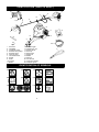
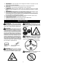
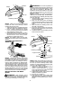
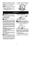
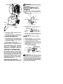
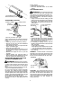
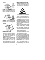
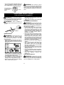
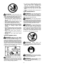
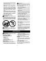
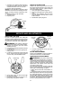
2500CXL
GB
FR
DE
ES
INSTRUCTION MANUAL
IMPORTANT INFORMATION: Please read these instructions carefully and make
sure you understand them before using this unit. Retain these instructions for future
reference.
MANUEL D’INSTRUCTIONS
RENSEIGNEMENTS IMPORTANTS: Avant d’utiliser cet appareil, veuillez lire
atentivement les instructions et assurez--vous de les avoir comprises. Conservez
les instructions pour référence ultérieure.
BETRIEBSANWEISUNG
WICHTIGE INFORMATION: Lesen Sie diese Hinweise zur Handhabung des
Geräts aufmerksam durch. Verwenden Sie es erst, wenn Sie sicher sind, daß Sie
alle Anweisungen verstanden haben und gut aufbewahren.
MANUAL DE INSTRUCCIONES
INFORMACIÓN IMPORTANTE: Lea atentamente las instrucciones y
asegúrese de entenderlas antes de utilizar esta aparato. Conserve las instrucciones para la referencia en el futuro.
115270826 Rev. 3
12/15/10 BRW
IDENTIFICATION (WHAT IS WHAT?)
18
2
4
10
6
9
8
7
12
1
16
13
19
15
3
14
20
1.
2.
3.
4.
5.
6.
7.
8.
9.
10.
11.
22
Fuel tank
Handlebar
ON/STOP switch
Shoulder strap clamp
Shoulder strap
Trimmer head
Line limiter blade
Shield
Shaft
Coupler
Blade
12.
13.
14.
15.
16.
17.
18.
19.
20.
21.
22.
Throttle trigger
Throttle lock--out
Starter handle
Fuel cap
Primer bulb
Start lever
Muffler
Wrench
Hex wrench
Instruction manual
Transport guard
5
IDENTIFICATION OF SYMBOLS
A.
D.
F.
I.
B.
E.
G.
J.
H.
K.
C.
21
17
11
2
A.
B.
C.
D.
E.
F.
G.
H.
I.
J.
K.
WARNING! This brushcutter can be dangerous! Careless or improper use can
cause serious or even fatal injury.
Read and understand the instruction manual before using the brushcutter.
Always use:
Ear protection, eye protection, head protection, boots, and gloves.
DANGER! Blade can thrust violently away from material it does not cut. Blade
thrust can cause amputation of arms or legs. Keep people and animals 15 meters
away.
WARNING! Blade/trimmer line can throw objects violently. You and others can be
blinded or injured. Always wear eye protection and leg protection.
The operator of the machine must insure that no one comes within a 15 meter radius
while working. When several operators are working within the same area a safety distance of at least 15 meters must be observed.
Use unleaded or quality leaded petrol and two--stroke oil mixed at a ratio of 2.5%.
Assist handle to be positioned only below the arrow.
Engine ON/STOP Switch.
Guaranteed sound power level according to Directive 2000/14/EC
Maximum rotational frequency of the spindle, rpm
SAFETY RULES
WARNING: When using gardening
appliances, basic safety precautions should always be followed to reduce the risk of fire and
serious injury. Read and follow all instructions.
DANGER: This power tool can be
dangerous! This unit can cause serious injury
including amputation or blindness to the operator and others. The warnings and safety
instructions in this manual must be followed to
provide reasonable safety and efficiency in
using the unit. The operator is responsible for
following the warnings and instructions in this
manual and on the unit. Read the entire instruction manual before assembling and using the unit! Restrict the use of this unit to persons who read, understand, and follow the
warnings and instructions in this manual and
on the unit. Never allow children to operate
this unit.hildren to operate this unit.
INSTRUCTION
MANUAL
WARNING: Blade/trimmer line can
throw objects violently. You and others can be
blinded or injured. Wear safety glasses and
leg protection.
WARNING: Hazard zone for thrown
objects. Blade/Trimmer line can throw objects
violently. Others can be blinded or injured.
Keep people and animals 15 meters away.
Hazard Zone
SAFETY INFORMATION
ON THE UNIT
DANGER: Blade can thrust violently
away from material it does not cut. Blade
thrust can cause amputation of arms or legs.
Keep people and animals 15 meters away.
WARNING: Do not use trimmer head
as a fastening device for the blade.
3
WARNING: The blade continues to
spin after the throttle is released or, engine is
turned off. The coasting blade can throw objects
or seriously cut if accidentally touched. Stop the
blade by contacting the right hand side of the
coasting blade with material already cut.
Stop coasting
blade by contact
with cut material.
OPERATOR SAFETY
WARNING: This machine produces
an electromagnetic field during operation. Under
some circumstances, this field may interfere
with active or passive medical implants. To reduce the risk of serious or fatal injury, we recommend persons with medical implants to consult
their physician and the medical implant
manufacturer before operating this machine.
S Dress properly. Always wear safety
glasses or similar eye protection when operating, or performing maintenance, on
your unit (safety glasses are available).
Eye protection should be marked Z87.
S Always wear face or dust mask if operation
is dusty.
S Always wear heavy, long pants, long
sleeves, boots, and gloves. Wearing safety
leg guards is recommended.
S Always wear foot protection. Do not go
barefoot or wear sandals. Stay clear of
blade/spinning line.
S Secure hair above shoulder length. Secure
or remove loose clothing or clothing with
loosely hanging ties, straps, tassels, etc.
They can be caught in moving parts.
S Being fully covered also helps protect you
from debris and pieces of toxic plants
thrown by spinning line.
S Stay alert. Do not operate this unit when you
are tired, ill, upset or under the influence of alcohol, drugs, or medication. Watch what you
are doing; use common sense.
S Wear hearing protection. Long or continuous exposure to high noise levels may
cause permanent hearing impairment.
S Mufflers fitted with catalytic converters get
very hot during use and remain so for some
time after stopping. This also applies at idle
speed. Contact can result in burns to the skin.
Remember the risk of fire!
S Never start or run inside a closed room or
building. Breathing exhaust fumes can kill.
S Keep handles free of oil and fuel.
S Always use the handlebar and a properly
adjusted shoulder strap with a blade (see
ASSEMBLY).
UNIT / MAINTENANCE SAFETY
WARNING: Stop unit and disconnect
the spark plug before performing maintenance (except carburetor adjustments).
S Throw away blades that are bent, warped,
cracked, broken, or damaged in any other
way. Replace trimmer head parts that are
cracked, chipped, broken, or damaged in
any other way before using the unit.
S Maintain unit according to recommended
procedures. Keep blade sharp. Keep cutting line at the proper length.
S Use only 3 mm diameter McCulloch brand
replacement line. Never use wire, rope,
string, etc.
S Install required shield properly before using
the unit.
S Use only specified blade or trimmer head;
make sure it is properly installed and securely fastened.
S Never start engine with clutch shroud removed. The clutch can fly off and cause serious injury.
S Be sure blade or trimmer head stops turning
when engine idles.
S Make carburetor adjustments with the lower end supported to prevent blade or trimmer line from contacting any object. Hold
unit by hand; do not use the shoulder strap
for support.
S Keep others away when making carburetor adjustments.
S Use only recommended McCulloch accessories and replacement parts.
S Have all maintenance and service not explained in this manual performed by your authorized service dealer.
FUEL SAFETY
S
S
S
S
S
S
S
S
Mix and pour fuel outdoors.
Keep away from sparks or flames.
Use a container approved for fuel.
Do not smoke or allow smoking near fuel or
the unit.
Avoid spilling fuel or oil. Wipe up all fuel spills.
Move at least 3 meters away from fueling
site before starting engine.
Stop engine and allow to cool before removing fuel cap.
Always store gasoline in a container approved for flammable liquids.
CUTTING SAFETY
WARNING: Inspect the area to be cut
before each use. Remove objects (rocks,
broken glass, nails, wire, string, etc.) which
can be thrown or become entangled in the
blade or trimmer head.
S Keep others including children, animals,
bystanders, and helpers at least 50 feet (15
meters) away. Stop engine immediately if
you are approached.
S Always keep engine on the right--hand side
of your body.
S Hold the unit firmly with both hands.
4
S Keep firm footing and balance. Do not
overreach.
S Keep blade or trimmer head below waist
level. Do not raise engine above your waist.
S Keep all parts of your body away from blade,
trimmer head, and muffler when engine is
running. A hot muffler can cause serious
burns.
S Cut from your left to your right. Cutting on
right side of the shield will throw debris
away from the operator.
S Use only in daylight or good artificial light.
S Use only for jobs explained in this manual.
TRANSPORTING AND STORAGE
S Allow the engine to cool; secure unit before
storing or transporting in vehicle.
S Empty fuel tank before storing or transporting the unit. Use up fuel left in the carburetor
by starting engine and letting it run until it
stops.
S Store unit and fuel in an area where fuel vapors cannot reach sparks or open flames
from water heaters, electric motors or
switches, furnaces, etc.
S Store unit so line limiter cannot accidentally
cause injury. Unit can be hung by the shaft.
S Always install transport guard on blade before transporting or strorage.
S Store the unit out of the reach of children.
S Secure the machine during transport.
SPECIAL NOTICE: Exposure to vibrations through prolonged use of gasoline powered hand tools could cause blood vessel or
nerve damage in the fingers, hands, and
joints of people prone to circulation disorders
or abnormal swellings. Prolonged use in cold
weather has been linked to blood vessel damage in otherwise healthy people. If symptoms
occur such as numbness, pain, loss of
strength, change in skin color or texture, or
loss of feeling in the fingers, hands, or joints,
discontinue the use of this tool and seek medical attention. An anti-vibration system does
not guarantee the avoidance of these problems. Users who operate power tools on a
continual and regular basis must monitor
closely their physical condition and the condition of this tool.
ASSEMBLY
CARTON CONTENTS
Check carton contents against the following
list:
S Powerhead
S Trimmer attachment
S Trimmer head
S Blade
S Cupped washer
S Large nut for installing blade
S Combination shield
S Bolt
S Handlebar
S Bracket cover
S Bracket cover screws (2)
S Hex wrench
S Wrench
S Shoulder strap
S Transport guard
WARNING: Always stop unit and disconnect spark plug before performing any assembly procedures.
WARNING: If received assembled,
repeat all steps to ensure your unit is properly
assembled and all fasteners are secure.
Examine parts for damage. Do not use damaged parts.
It is normal for the fuel filter to rattle in the
empty fuel tank.
Finding fuel or oil residue on muffler is normal
due to carburetor adjustments and testing
done by the manufacturer.
INSTALLING BRUSHCUTTER
ATTACHMENT
CAUTION: When installing brushcutter at-
tachment, place the unit on a flat surface for
stability.
1. Loosen the coupler by turning the knob
counterclockwise.
Coupler
Shipping
protector
LOOSEN
Knob
TIGHTEN
2. Remove shipping protector from coupler.
3. Remove the shaft cap from the brushcutter
attachment (if present).
4. Position locking/release button of attachment into guide recess of coupler.
5. Push the attachment into the coupler until
the locking/release button snaps into the
primary hole.
6. Before using the unit, tighten the knob securely by turning clockwise.
TOOLS REQUIRED
S Hex wrench (provided)
S Adjustable wrench
S Phillips screwdriver
5
Coupler Primary Hole
Guide Recess
Upper
Shaft
Locking/
Release Attachment
Button
Bracket Cover
Mounting
Bracket
WARNING:
Make sure the locking/
release button is locked in the primary hole
and the knob is securely tightened before operating the unit. All attachments are designed
to be used in the primary hole unless otherwise
stated in the applicable attachment instruction
manual. Using the wrong hole could lead to serious injury or damage to the unit.
Locking/Release
Button in Primary Hole
For optional attachments, see the ASSEMBLY section of the applicable attachment instruction manual.
ATTACHING THE HANDLEBAR
DANGER: To avoid serious injury, the
barrier portion of the handlebar must be installed
as shown to provide a barrier between operator
and the spinning blade.
1. Locate the decal on the handlebar. This
decal includes an arrow. Position the handlebar with the mounting bracket at the
end of the arrow.
2. Align hole in handlebar with pin on mounting bracket.
Screw
Handlebar
ASSEMBLY OF SHOULDER STRAP
Proper shoulder strap and handlebar adjustments must be made with the engine completely stopped before using unit.
1. Insert your right arm and head through the
shoulder strap and allow it to rest on your
left shoulder. Make sure the danger sign
is on your back and the hook is to the right
side of your waist.
NOTE: A one-half twist is built in the shoulder strap to allow the strap to rest flat on the
shoulder.
2. Adjust the strap, allowing the hook to be
about 15 cm below the waist.
3. Fasten the strap hook to the clamp located
between the trigger handle and the handlebar clamp base and lift the tool to the operating position.
4. Try on shoulder strap and adjust for fit and
balance before starting the engine or beginning a cutting operation.
NOTE: It may be necessary to relocate the
shoulder strap clamp on the shaft for proper
balancing of unit.
TO RELOCATE SHOULDER STRAP
CLAMP:
1. Loosen and remove both clamp screws.
2. Place the upper shoulder strap clamp
over the shaft.
3. Position the lower shoulder strap clamp
under the shaft and align the upper and
lower clamp screw holes.
Upper Shoulder
Strap Clamp
Pin
Mounting
Bracket
3. Position the bracket cover over the handlebar. Again make sure the handlebar is
at the end of the arrow.
4. Insert screws and hand tighten only. Be
sure the handlebar is installed correctly;
then, tighten each screw securely with
the hex wrench.
Lower Shoulder
Strap Clamp
Screws
4. Insert two screws into the screw holes.
5. Secure shoulder strap clamp by tightening screws with a hex wrench.
6
HARNESS
ADJUSTMENT
FOR BALANCE
15 cm
below
waist
76 cm
Bolt
10 -- 30 cm
above
ground
CONFIGURING YOUR UNIT
You can configure your unit using a cutting head
for grass and light weeds, or a weed blade for
cutting grass, weeds, and brush up to 1 cm in
diameter. To assemble your unit, go to the section for the desired configuration and follow the
instructions.
76 cm
ASSEMBLY INFORMATION -TRIMMER HEAD
TRIMMER
HEAD
ATTACHING THE SHIELD
WARNING: The shield must be properly installed. The shield provides partial
protection to the operator and others from the
risk of thrown objects, and is equipped with a
line limiter blade which cuts excess line to the
proper length. The line limiter blade (on underside of shield) is sharp and can cut you.
1. Insert bracket into slot on shield.
2. Pivot shield to align holes in shield and
bracket.
Bracket
Slot
Shield
3. Secure shield to bracket with bolt.
NOTE: Remove the blade before attaching the
trimmer head. To remove blade, align hole in
the dust cup with the hole in the side of the
gearbox by rotating the blade. Insert a small
screwdriver into aligned holes. This will keep
the shaft from turning while loosening the blade
nut. Remove blade nut by turning clockwise.
Remove the screwdriver. Remove both washers and blade. See INSTALLATION OF THE
METAL BLADE for illustrations. Be sure to store
all parts and instructions for future use.
INSTALLATION OF THE TRIMMER
HEAD
NOTE: If your unit has a plastic cover over
the threads on the threaded shaft, remove the
covering to expose the threads. Before installing the trimmer head, make sure the dust cup
and retaining washer are positioned on the
gearbox as shown below.
7
Shield
Gearbox
Dust cup
Retaining washer
NOTE: Make sure all parts are properly
installed as shown in the illustration before
installing the trimmer head.
1. Align hole in the dust cup with the hole in the
side of the gearbox by rotating the dust cup.
2. Insert a small screwdriver into aligned
holes. This will keep the shaft from turning
while tightening trimmer head.
3. While holding the screwdriver in position,
thread trimmer head onto the shaft in the
direction shown on the decal (counterclockwise). Tighten until secure.
NOTE: The retaining washer must be positioned with the raised section facing toward the
gearbox.
WARNING: Do not use any blades, or
fastening hardware other than the washers and
nuts shown in the following illustrations. These
parts must be provided by McCulloch and
installed as shown below. Failure to use proper
parts can cause the blade to fly off and seriously
hurt you or others.
NOTE: The dust cup is located on the gearbox
shaft and not in the parts bag. All other fasteners mentioned in the following assembly steps
are in the parts bag.
1. Install the blade and the retaining washer
over the threaded shaft.
2. Make sure the raised part of the retaining
washer is facing the gearbox and the raised
area fits into the hole in the center of the
blade.
3. Slide the blade and retaining washer onto
the shaft of the gearbox.
4. Place the cupped washer onto the shaft.
Make sure the cupped side of the washer
is toward the blade.
5. Install the blade nut by threading onto the
shaft counterclockwise.
Gearbox
Shield
ASSEMBLY INFORMATION -WEED BLADE
Dust cup
Threaded
shaft
WEED
BLADE
Retaining washer
Cupped washer
Blade
Nut
Wrench
NOTE: Remove the trimmer head before
installing the weed blade. To remove the trimmer
head, align hole in the dust cup with the hole in
the side of the gearbox by rotating the dust cup.
Insert a small screwdriver into aligned holes.
This will keep the shaft from turning while loosening the trimmer head. Remove the trimmer
head by turning clockwise. Remove the screwdriver. See INSTALLATION OF THE CUTTING
HEAD for illustrations. Be sure to store all parts
and instructions for future use. Never use the
trimmer head with the metal blade installed.
INSTALLATION OF THE METAL
BLADE
WARNING: Wear protective gloves
when handling or performing maintenance on
the blade to avoid injury. The blade is sharp and
can cut you even when it is not moving.
NOTE: Make sure all parts are in place as il-
lustrated, and the blade is sandwiched between
the dust cup and the retaining washer. There
should be no space between the blade and the
dust cup or the retaining washer.
6. Align hole in dust cup with hole in side of
gearbox by rotating the blade.
7. Insert a small screwdriver into aligned
holes. This will keep the shaft from turning
while tightening the blade nut.
8. Tighten blade nut firmly with a wrench while
holding screwdriver in position.
9. Remove the screwdriver.
10. Turn blade by hand. If the blade binds
against the shield, or appears to be uneven,
the blade is not centered, and you must reinstall.
8
NOTE: To remove blade, insert screwdriver
into aligned holes. Unthread the nut and remove
parts. Be sure to store parts and instructions for
future use.
3. Place wire retainer over blade and insert
both ends of wire retainer back into clips.
Wire retainer
ATTACHING THE TRANSPORT
GUARD
NOTE: The transport guard must always be
attached to the blade when the machine is being transported or in storage.
1. Remove ends of wire retainer from the
clips on the transport guard.
2. Lift wire retainer and position blade in
transport guard.
Transport
guard
Clip
OPERATION
WARNING:
Be sure to read the fuel
information in the safety rules before you begin. If you do not understand the safety rules,
do not attempt to fuel your unit. Contact an
authorized service dealer.
HOW TO STOP YOUR UNIT
S To stop the engine, move the ON/STOP
switch to the STOP position.
FUELING ENGINE
WARNING:
Remove fuel cap slowly
when refueling.
This engine is certified to operate on unleaded
petrol. Before operation, petrol must be mixed
with a good quality 2--cycle air--cooled engine oil
designed to be mixed at a ratio of 40:1. A 40:1
ratio is obtained by mixing 5 liters of unleaded
petrol with 0,125 liter of oil. DO NOT USE automotive oil or marine oil. These oils will cause engine damage. When mixing fuel, follow instructions printed on oil container. Once oil is added
to petrol, shake container momentarily to assure
that the fuel is thoroughly mixed. Always read
and follow the safety rules relating to fuel before
fueling your unit.
CAUTION: Never use straight petrol in your
unit. This will cause permanent engine damage.
FUEL REQUIREMENTS
Use good quality unleaded petrol. The lowest
recommended octane grade is 90 (RON).
IMPORTANT
Use of alcohol blended fuels (more than 10% alcohol) can cause major engine performance
and durability problems.
WARNING: Incorrect use of fuel and/
or lubricants will cause problems such as:
improper clutch engagements, overheating, vapor lock, power loss, lubrication deficiency, deterioration of fuel lines, gaskets
and internal carburetor components, etc.
Alcohol blended fuels will cause a high absorption of moisture in the fuel/oil mixture,
causing the separation of oil and fuel.
ON/STOP
Switch
HOW TO START YOUR UNIT
WARNING: Avoid any contact with the
muffler. A hot muffler can cause serious burns.
STARTING A COLD ENGINE (or a
warm engine after running out of fuel)
Starting position
NOTE: The throttle lock--out is designed to
prevent unintentional use of the throttle trigger. The lock--out must be pressed with the
palm of your hand as you grip the throttle handle before the trigger can be used. DO NOT
squeeze the throttle trigger until the engine
has started and runs.
1. Set unit on a flat surface.
2. Move ON/STOP switch to the ON position.
3. Slowly press the primer bulb 6 times.
4. Move the start lever to the START position.
9
Primer Bulb
WARNING: Always stop unit and disconnect spark plug before removing or installing attachments.
REMOVING TRIMMER ATTACHMENT (OR OTHER OPTIONAL ATTACHMENTS)
CAUTION: When removing or installing at-
Start
Lever
tachments, place the unit on a flat surface for
stability.
1. Loosen the coupler by turning the knob
counterclockwise.
Coupler
Attachment
LOOSEN
Throttle
lock--out
Knob
Starter
Handle
5. Pull starter rope handle sharply until engine starts and runs.
6. Allow unit to run for 10--15 seconds, then
fully squeeze the throttle trigger to disengage the starting system.
STARTING A WARM ENGINE
1. Move ON/STOP switch to the ON position.
2. Squeeze and hold the throttle trigger.
Keep throttle trigger fully squeezed until
engine runs smoothly.
3. Pull starter rope sharply while squeezing
throttle trigger until engine runs.
NOTE: Normally, the warm starting procedure
can be used within 5 -- 10 minutes after the unit
is turned STOP. If the unit sits for more than 10
minutes without being run, it will be necessary to
start the unit by following the steps under
STARTING A COLD ENGINE or following the
starting instruction steps shown on the unit.
TIGHTEN
2. Press and hold the locking/release button.
Locking/Release
Button
Attachment
Coupler
Upper Shaft
3. While securely holding the engine and upper shaft, pull the attachment straight out
of the coupler.
INSTALLING OPTIONAL ATTACHMENTS
1. Remove the shaft cap from the attachment (if present).
2. Position locking/release button of attachment into guide recess of coupler.
3. Push the attachment into the coupler until
the locking/release button snaps into the
primary hole.
4. Before using the unit, tighten the knob securely by turning clockwise.
Coupler Primary Hole
Guide Recess
STARTING A FLOODED ENGINE
Flooded engines can be started by placing
the ON/STOP switch in the ON position.
Move the start lever to the RUN position and
fully squeeze throttle trigger. Pull the starter
handle repeatedly while squeezing throttle
trigger until engine starts and runs. This could
require pulling the starter handle many times,
depending on how badly the unit is flooded.
If the unit still doesn’t start, refer to TROUBLESHOOTING TABLE.
OPERATING THE COUPLER
This model is equipped with a coupler which
enables optional attachments to be installed.
Upper
Shaft
Locking/
Release Attachment
Button
WARNING: Make sure the locking/
release button is locked in the primary hole
and the knob is securely tightened before operating the unit. All attachments are designed
to be used in the primary hole unless otherwise
stated in the applicable attachment instruction
manual. Using the wrong hole could lead to serious injury or damage to the unit.
10
To stop engine:
S Release the throttle trigger.
S Move the ON/STOP switch to the STOP
position.
CUTTING METHODS
Locking/Release
Button in Primary Hole
OPERATING POSITION
ALWAYS WEAR:
Hearing
protection
Safety helmet
Eye protection
WARNING: Use minimum speed and
do not crowd the line when cutting around
hard objects (rock, gravel, fence posts, etc.),
which can damage the trimmer head, become
entangled in the line, or be thrown causing a
serious hazard.
S The tip of the line does the cutting. You will
achieve the best performance and minimum
line wear by not crowding the line into the
cutting area. The right and wrong ways are
shown below.
Tip of line does
Line crowded into
the cutting.
work area.
Heavy,
long pants
Boots
Cut from your left to your right.
When operating unit, clip shoulder strap onto
clamp, stand as shown and check for the following:
S Wear eye protection and heavy clothing.
S Extend your left arm and hold handlebar
grip with your left hand.
S Hold throttle grip with your right hand with
finger on throttle trigger.
S Keep unit below waist level.
S Keep shoulder strap pad centered on your
left shoulder and danger sign centered on
your back.
S Maintain full weight of tool on your left
shoulder.
S Without bending over, keep the blade or
trimmer head near and parallel to the ground
and not crowded into material being cut.
OPERATING INSTRUCTIONS FOR
USE WITH TRIMMER HEAD
WARNING: Always wear eye protection. Never lean over the trimmer head. Rocks
or debris can ricochet or be thrown into eyes
and face and cause blindness or other serious
injury.
Before trimming, bring engine to a speed sufficient to cut material to be trimmed.
Do not run the engine at a higher speed than
necessary. The cutting line will cut efficiently
when the engine is run at less than full throttle.
At lower speeds, there is less engine noise and
vibration. The cutting line will last longer and will
be less likely to “weld” onto the spool.
Always release the throttle trigger and allow
the engine to return to idle speed when not
cutting.
Right
Wrong
S The line will easily remove grass and weeds
from around walls, fences, trees and flower
beds, but it also can cut the tender bark of
trees or shrubs and scar fences.
S For trimming or scalping, use less than full
throttle to increase line life and decrease head
wear, especially:
S During light duty cutting.
S Near objects around which the line can wrap
such as small posts, trees or fence wire.
S For mowing or sweeping, use full throttle for a
good clean job.
TRIMMING -- Hold the bottom of the trimmer
head about 8 cm above the ground and at an
angle. Allow only the tip of the line to make contact. Do not force trimmer line into work area.
Trimming
8 cm above
ground
SCALPING -- The scalping technique removes
unwanted vegetation down to the ground. Hold
the bottom of the trimmer head about 8 cm
above the ground and at an angle. Allow the tip
of the line to strike the ground around trees,
posts, monuments, etc. This technique increases line wear.
11
Scalping
S WHEN BLADE THRUST OCCURS -Blade Thrust can occur without warning if
the blade snags, stalls, or binds. This is
more likely to occur in areas where it is
difficult to see the material being cut. By
using the unit properly, the occurrence of
blade thrust will be reduced and the
operator will be less likely to lose control.
MOWING -- Your trimmer is ideal for mowing
in places conventional lawn mowers cannot
reach. In the mowing position, keep the line
parallel to the ground. Avoid pressing the
head into the ground as this can scalp the
ground and damage the tool.
Mowing
SWEEPING -- The fanning action of the rotating line can be used to blow away loose debris
from an area. Keep the line parallel to and
above the area surface and swing the tool
from side to side.
Sweeping
OPERATING INSTRUCTIONS FOR
USE WITH WEED BLADE
S Blade Thrust is a reaction that only occurs
when using a bladed unit. This reaction can
cause serious injury such as amputation.
Carefully study this section. It is important that
you understand what causes blade thrust,
how you can reduce the chance of its
occurring, and how you can remain in control
of unit if blade thrust occurs.
S WHAT CAUSES BLADE THRUST -- Blade
Thrust can occur when the spinning blade
contacts an object that it does not cut. This
contact causes the blade to stop for an instant
and then suddenly move or “thrust” away
from the object that was hit. The “thrusting”
reaction can be violent enough to cause the
operator to be propelled in any direction and
lose control of the unit. The uncontrolled unit
can cause serious injury if the blade contacts
the operator or others.
S Cut only grass, weeds, and woody brush up
to 1 cm in diameter with the weed blade. Do
not let the blade contact material it cannot cut
such as stumps, rocks, fences, metal, etc., or
clusters of hard, woody brush having a
diameter greater than 1 cm.
S Keep the blade sharp. A dull blade is more
likely to snag and thrust.
S Cut only at full throttle. The blade will have
maximum cutting power and is less likely to
bind or stall.
S “Feed” the blade deliberately and not too
rapidly. The blade can thrust away if it is fed
too rapidly.
S Cut only from your left to your right. Cutting on
right side of the shield will throw debris away
from the operator.
S Use the shoulder strap and keep a firm grip
on the unit with both hands. A properly
adjusted shoulder strap will support the
weight of the unit, freeing your arms and
hands to control and guide the cutting motion.
S Keep feet comfortably spread apart and
braced for a possible sudden, rapid thrust of
unit. Do not overreach. Keep firm footing and
balance.
S Keep blade below waist level; it will be
easier to maintain control of unit.
S Do not raise the engine above your waist as
the blade can come dangerously close to
your body.
S Do not swing unit with such force that you
are in danger of losing your balance.
Bring the engine to cutting speed before entering the material to be cut. If the blade does not
turn when you squeeze the throttle trigger, make
sure shaft is fully inserted into the engine.
Always release the throttle trigger and allow
engine to return to idle speed when not cutting. The blade should not turn while the engine is running at idle. If the blade turns at idle,
do not use your unit. Refer to the CARBURETOR ADJUSTMENT section or contact your
authorized service dealer.
S Maintain good firm footing while using the
unit. Do this by planting feet firmly in a
comfortable apart position.
S Cut while swinging the upper part of your
body from left to right.
12
S As you move forward to the next area to cut,
be sure to maintain your balance and footing.
RECOMMENDED CUTTING POSITION
2 o’clock
Cut using the 2
o’clock to 4 o’clock
position of the
blade
4 o’clock
WARNING: The operator or others
must not try to clear away cut material with the
engine running or the blade turning to avoid
serious injury. Stop engine and blade before
removing materials wrapped around blade or
shaft.
ADDITIONAL SAFETY RULES
FOR OPTIONAL ATTACHMENTS
WARNING: For each optional attach-
ment used, read entire instruction manual before use and follow all warnings and instructions in manual and on attachment.
WARNING:
Ensure handlebar is
installed on upper shaft (engine end of unit) at
all times.
Handlebar
EDGER SAFETY
WARNING: Inspect the area to be
edged before each use. Remove objects
(rocks, broken glass, nails, wire, etc.) which
can be thrown by the blade or can wrap
around the shaft.
S Blade rotates momentarily after the trigger is
released. The blade can seriously cut you or
others. Allow blade to stop before removing it
from the cut.
S Throw away blades that are bent, warped,
cracked, broken or damaged in any other
way. Replace parts that are cracked, chipped,
or damaged before using the unit.
S Do not attempt to remove cut material nor
hold material to be cut when the engine is
running or when cutting blade is moving.
S Always keep the wheel and depth adjusting
skid in contact with the ground.
S Always push the unit slowly over the ground.
Stay alert for uneven sidewalks, holes in the
terrain, large roots, etc.
S Always use the handlebar when using edger
attachment.
BLOWER/VACUUM SAFETY
WARNING: Inspect area before starting unit. Remove all debris and hard objects
such as rocks, glass, wire, etc. that can ricochet, be thrown, or otherwise cause injury or
damage during operation.
S Do not set unit on any surface except a clean,
hard area while engine is running. Debris
such as gravel, sand, dust, grass, etc., could
be picked up by the air intake and thrown out
through discharge opening, damaging unit,
property, or causing serious injury to
bystanders or operator.
S Never place objects inside the blower tubes,
vacuum tubes or blower outlet. Always direct
the blowing debris away from people,
animals, glass, and solid objects such as
trees, automobiles, walls, etc. The force of air
can cause rocks, dirt, or sticks to be thrown or
to ricochet which can hurt people or animals,
break glass, or cause other damage.
S Never run unit without the proper equipment
attached.
S Check air intake opening frequently always
with engine stopped and spark plug
disconnected. Keep vents and discharge
tubes free of debris which can accumulate
and restrict proper air flow.
S Never place any object in air intake opening
as this could restrict proper air flow and cause
damage to the unit.
S Never use for spreading chemicals, fertilizers,
or other substances which may contain toxic
materials.
S To avoid spreading fire, do not use near leaf or
brush fires, fireplaces, barbecue pits,
ashtrays, etc.
CULTIVATOR SAFETY
WARNING: Rotating tines can cause
serious injury. Keep away from rotating tines.
Stop the engine and disconnect the spark plug
before unclogging tines or making repairs.
13
S Do not use a cutting blade that is bent,
warped, cracked, broken or damaged in any
other way. Have worn or damaged parts
replaced by your authorized service dealer.
S Always keep unit in front of your body. Keep
all parts of your body away from the cutting
blade.
S Keep the cutting blade and air vents clear of
debris.
POLE PRUNER SAFETY
WARNING:
Inspect the area to be
cultivated before starting the unit. Remove all
debris and hard and sharp objects such as
rocks, vines, branches, rope, string, etc.
S Avoid heavy contact with solid objects that
might stop the tines. If heavy contact occurs,
stop the engine and inspect the unit for
damage.
S Never operate the cultivator without the tine
cover in place and properly secured.
S Keep the tines and guard clear of debris.
S After striking a foreign object, stop the engine,
disconnect the spark plug and inspect the
cultivator for damage. Repair before
restarting.
S Disconnect attachment from the drive engine
before cleaning the tines with a hose and
water to remove any build--up. Oil the tines to
prevent rust.
S Always wear gloves when servicing or
cleaning the tines. The tines become very
sharp from use.
S Do not run unit at high speed unless
cultivating.
WARNING: The reciprocating blade/
rotating chain can cause severe injury. Inspect the unit before use. Do not operate unit
with a bent, cracked or dull blade or dull chain.
Keep away from the blade/chain.
WARNING: The reciprocating blade/
rotating chain is sharp. Do not touch. To prevent serious injury, always stop engine and
ensure blade/chain has stopped moving, disconnect spark plug, and wear gloves when
changing or handling the blade or chain.
WARNING: A coasting blade/rotating
chain can cause injury while it continues to
move after the engine is stopped. Maintain
proper control of the unit until the blade/chain
has completely stopped moving. Keep
hands, face and feet at a distance from all
moving parts. Do not attempt to touch or stop
the blade or chain when it is moving.
HEDGE TRIMMER SAFETY
DANGER: RISK OF CUT; KEEP
HANDS AWAY FROM BLADE -- Blade
moves momentarily after the trigger is released. Do not attempt to clear away cut material when the blade is in motion. Make sure
the switch is in the STOP position, the spark
plug wire is disconnected, and the blade has
stopped moving before removing jammed
material from the cutting blade. Do not grab or
hold the unit by the cutting blade.
WARNING: Inspect the area before
starting the unit. Remove all debris and hard
objects such as rocks, glass, wire, etc. that
can ricochet, be thrown, or otherwise cause
injury or damage during operation.
WARNING: Falling objects can
cause severe head injury. Wear head protection when operating this unit with a pole pruner attachment.
WARNING: To prevent serious injury,
do not use more than one boom extension
with a pole pruner attachment.
WARNING: Keep the pruner away
from power lines or electrical wires.
S Only use for pruning limbs or branches up to
10 cm in diameter.
14
S Do not operate the unit faster than the speed
needed to prune. Do not run the unit at high
speed when not pruning.
S Always stop the unit when work is delayed or
when walking from one cutting location to
another.
S If you strike or become entangled with a
foreign object, stop the engine immediately
and check for damage. Have any damage
repaired by an authorized service dealer
before attempting further operations. Discard
blades that are bent, warped, cracked or
broken.
S Stop the unit immediately if you feel excessive
vibration. Vibration is a sign of trouble. Inspect
thoroughly for loose nuts, bolts or damage
before continuing. Contact an authorized
service dealer for repair or replacement of
affected parts as necessary.
SNOW THROWER SAFETY
WARNING: Keep hands and feet
away from the rotor when starting or running
the engine. Never attempt to clear the rotor
with the engine/motor running. Stop engine
and disconnect spark plug before unclogging
snow or debris from discharge chute or when
adjusting vanes.
WARNING: Never lean over discharge chute. Rocks or debris could be
thrown into the eyes and face and cause serious injury or blindness.
WARNING: Inspect the area where
the unit is to be used. Remove objects that
could be thrown or damage the unit. Some
objects may be hidden by fallen snow -- be
alert for the possibility.
S Direct material discharge away from glass
enclosures, automobiles, etc.
S Do not run engine at high speed while not
removing snow.
S Be attentive when using the snowthrower,
and stay alert for holes in the terrain and other
hidden hazards.
S Make sure the rotor will spin freely before
attaching the snowthrower to the powerhead.
S If the rotor will not rotate freely due to frozen
ice, thaw the unit before thoroughly before
attempting to operate under power.
S Keep the rotor clear of debris.
S Do not throw snow near other people. The
snow thrower could propel small objects at
high speed causing injury.
S After striking a foreign object, stop the engine,
disconnect spark plug and inspect the
snowthrower for damage and repair if
necessary before restarting unit.
S Never operate the snowthrower near glass
enclosures, automobiles and trucks.
S Never attempt to use the snowthrower on a
roof.
S Never operate the snowthrower near window
wells, dropoffs, etc.
S Never discharge snow onto public roads or
near moving traffic.
S Clear snow from slopes by going up and
down; never across. Use caution when
changing directions. Never clear snow from
steep slopes.
S Let snowthrower run for a few minutes after
clearing snow so moving parts do not freeze.
S Look behind and use care when backing up.
Exercise caution to avoid slipping or falling,
especially when operating in reverse.
S Know how to stop quickly.
MAINTENANCE
WARNING:
Disconnect the spark
plug before performing maintenance except
for carburetor adjustments.
CHECK FOR LOOSE
FASTENERS AND PARTS
S
S
S
S
S
Spark Plug Boot
Air Filter
Housing Screws
Handlebar Screws
Combination Shield
CHECK FOR DAMAGED OR
WORN PARTS
Contact an authorized service dealer for replacement of damaged or worn parts.
S ON/STOP Switch -- Ensure ON/STOP switch
functions properly by moving the switch to the
STOP position. Make sure engine stops; then
restart engine and continue.
S Fuel Tank -- Discontinue use of unit if fuel
tank shows signs of damage or leaks.
S Debris Shield -- Discontinue use of unit if
debris shield is damaged.
INSPECT AND CLEAN UNIT AND
LABELS
S After each use, inspect complete unit for
loose or damaged parts. Clean the unit and
labels using a damp cloth with a mild detergent.
S Wipe off unit with a clean dry cloth.
CLEAN AIR FILTER
A dirty air filter decreases engine performance and increases fuel consumption and
harmful emissions. Always clean after every
5 hours of operation.
15
1. Clean the cover and the area around it to
keep dirt from falling into the carburetor
chamber when the cover is removed.
2. Remove parts as illustrated.
NOTE: Do not clean filter in gasoline or other
flammable solvent to avoid creating a fire hazard or producing harmful evaporative emissions.
3. Wash the filter in soap and water.
4. Allow filter to dry.
5. Replace parts.
REPLACE SPARK PLUG
Replace the spark plug each year to ensure
the engine starts easier and runs better. Set
spark plug gap at 0,6 mm. Ignition timing is
fixed and nonadjustable.
1. Twist, then pull off spark plug boot.
2. Remove spark plug from cylinder and discard.
3. Replace with Champion RCJ-6Y spark
plug and tighten securely with a 19 mm
socket wrench.
4. Reinstall the spark plug boot.
Button
Air Filter
Air Filter Cover
SERVICE AND ADJUSTMENTS
REPLACING THE LINE
Line exit
tunnel
For unit to operate properly, the cutting line
should be replaced when line becomes worn to
less than 8 cm in length from the edge of the line
exit tunnels on each side of the cutting head.
WARNING: Only replace cutting line
with ON/STOP switch in the STOP position.
1. Remove and discard worn line before
installing new line.
2. Use only 3 mm diameter McCulloch brand
cut length line.
3. Insert one end of the line through the positioning tunnel.
4. Continue to feed line through tunnel until
line is centered (leaving equal amounts
on each side). See illustration below.
Line exit
tunnel
7. Correctly installed line will be the same
length on both ends.
BLADE REPLACEMENT
Refer to the ASSEMBLY section for blade replacement instructions and illustrations.
CARBURETOR ADJUSTMENT
Positioning
tunnel
5. Insert ends of line one at a time through
the line exit tunnels.
6. Pull the line and make sure the line is extended fully through the tunnels.
WARNING: Keep others away when
making idle speed adjustments. The trimmer
head will be spinning during most of this procedure. Wear your protective equipment and
observe all safety precautions. After making
adjustments, the trimmer head must not
move/spin at idle speed.
The carburetor has been carefully set at the
factory. Adjustments may be necessary if you
notice any of the following conditions:
S Engine will not idle when the throttle is released.
S The trimmer head moves/spins at idle speed.
Make adjustments with the unit supported so
the cutting attachment is off the ground and
will not make contact with any object. Hold
the unit by hand while running and making adjustments. Keep all parts of your body away
from the cutting attachment and muffler.
16
Idle Speed Adjustment
Idle Speed Screw
Allow engine to idle. Adjust speed until engine
runs without trimmer head moving or spinning
(idle speed too fast) or engine stalling (idle
speed too slow).
S Turn idle speed screw clockwise to increase engine speed if engine stalls or dies.
S Turn idle speed screw counterclockwise to
decrease engine speed if trimmer head
moves or spins at idle speed.
Air Filter Cover
WARNING:
Recheck the idle speed
after each adjustment. The trimmer head
must not move or spin at idle speed to avoid
serious injury to the operator or others.
If you require further assistance or are unsure
about performing this procedure, contact an
authorized service dealer.
STORAGE
WARNING:
Perform the following
steps after each use:
S Allow engine to cool before storing or transporting.
S Store unit and fuel in a well ventilated area
where fuel vapors cannot reach sparks or
open flames from water heaters, electric
motors or switches, furnaces, etc.
S Empty fuel tank before storing or transporting the unit.
S Store unit and fuel well out of the reach of
children.
S Store unit with all guards in place. Position
unit so that any sharp object cannot accidentally cause injury.
SEASONAL STORAGE
Prepare unit for storage at end of season or if
it will not be used for 30 days or more.
If your unit is to be stored for a period of time:
S Clean the entire unit before lengthy storage.
S Store in a clean dry area.
S Lightly oil external metal surfaces.
ENGINE
S Remove spark plug and pour 1 teaspoon of
40:1, 2-cycle engine oil (air cooled) through
the spark plug opening. Slowly pull the
starter rope 8 to 10 times to distribute oil.
S Replace spark plug with new one of recommended type and heat range.
S Clean air filter.
S Check entire unit for loose screws, nuts,
and bolts. Replace any damaged, broken,
or worn parts.
S At the beginning of the next season, use
only fresh fuel having the proper gasoline to
oil ratio.
OTHER
S Do not store gasoline from one season to
another.
S Replace your gasoline can if it starts to rust.
17
TROUBLESHOOTING TABLE
WARNING: Always stop unit and disconnect spark plug before performing all of the
recommended remedies below except remedies that require operation of the unit.
TROUBLE
CAUSE
Engine will not
start.
1. ON/STOP switch in STOP 1. Move ON/STOP switch to ON
position.
position.
2. Engine flooded.
2. See “Starting a Flooded Engine” in
Operation Section.
3. Fuel tank empty.
3. Fill tank with correct fuel mixture.
4. Spark plug not firing.
4. Install new spark plug.
5. Fuel not reaching
5. Check for dirty fuel filter; replace.
carburetor.
Check for kinked or split fuel line;
repair or replace.
6. Carburetor requires
6. Contact an authorized service dealer.
adjustment.
Engine will
not idle
properly.
1. Carburetor requires
adjustment.
2. Crankshaft seals worn.
3. Compression low.
1. Air filter dirty.
2. Spark plug fouled.
Engine will not
accelerate,
lacks power,
or dies under
a load.
Engine
smokes
excessively.
Engine runs
hot.
3. Carburetor requires
adjustment.
4. Carbon build-up on
muffler outlet screen.
5. Compression low.
1. Choke partially on.
2. Fuel mixture incorrect.
3. Air filter dirty.
4. Carburetor requires
adjustment.
1. Fuel mixture incorrect.
2. Spark plug incorrect.
3. Carburetor requires
adjustment.
4. Carbon build-up on
muffler outlet screen.
REMEDY
1. See “Carburetor Adjustment” in
Service and Adjustments Section.
2. Contact an authorized service dealer.
3. Contact an authorized service dealer.
1. Clean or replace air filter.
2. Clean or replace plug
and regap.
3. Contact an authorized service dealer.
4. Contact an authorized service dealer.
5. Contact an authorized service dealer.
1. Adjust choke.
2. Empty fuel tank and refill with
correct fuel mixture.
3. Clean or replace air filter.
4. Contact an authorized service dealer.
1. Empty fuel tank and refill with
correct fuel mixture.
2. Replace with correct spark plug.
3. Contact an authorized service dealer.
4. Contact an authorized service dealer.
18
DECLARATION OF CONFORMITY
EC Declaration of Conformity (Only applies to Europe)
We, Husqvarna AB, SE-561 82 Huskvarna, Sweden, tel: +46--36--146500, as authorised
representative in the Community, declare that the brushcutter model McCulloch 2500CXL
with serial numbers dating from 2009 and onwards (the year is clearly stated on the rating
plate, followed by the serial number), comply with the requirements of the COUNCIL’S
DIRECTIVES:
of 17 May 2006 “relating to machinery” 2006/42/EC;
of 15 December 2004 “relating to electromagnetic compatibility” 2004/108/EC, and applicable
supplements; and
of 8 May 2000 “relating to the noise emissions in the environment” in accordance with Annex
V of 2000/14/EC. For information relating to noise emissions, see Technical data section.
The following standards have been applied: EN ISO 12100-- 1/A1:2009, EN ISO
12100-- 2/A1:2009, CISPR 12:2007, EN 11806:2008.
SMP, The Swedish Machinery Testing Institute, Fyrisborgsgatan 3 S--754 50 Uppsala,
Sweden, has performed voluntary type examination on behalf of Husqvarna AB. The
certificate(s) are numbered: SEC/09/2028.
09--11--01
Ronnie E. Goldman, Director of Engineering
Authorized representative for Husqvarna AB and
responsible for technical documentation
19
TECHNICAL DATA SHEET
MODEL: 2500CXL
25
Cylinder displacement, cm3
At maximum engine power, rpm
8000
Maximum rotational frequency of the spindle
10000
Engine speed at recommended maximum spindle
rotational frequency
7400
Recommended speed idling, rpm
2900
Maximum engine power, measured in
accordance with ISO 8893, kW
0,7
Catalytic converter muffler
Yes
IGNITION SYSTEM
Spark plug
Champion RCJ--6Y
Electrode gap, mm
0,6
FUEL AND LUBRICATION SYSTEM
340
Fuel tank capacity, cm3
WEIGHT
Weight without fuel, cutting attachment and guard, kg
3,7
NOISE EMISSIONS
(see Note 1)
Sound power level, measured dB(A)
108
114
Sound power level, guaranteed LWA dB(A)
NOISE LEVELS
(see Note 2)
Equivalent sound pressure level at the operators’ ear,
measured according to EN/ISO 11806 and ISO 22868,
dB(A)
Equipped with grass blade (original)
96,4
Equipped with trimmer head (original)
96,4
VIBRATION LEVELS
(see Note 3)
Equivalent vibration levels (ahv,eq) at handles, measured
according to EN ISO 11806 and ISO 22867, m/s2
Equipped with grass blade (original), left/right
7,2/7,5
Equipped with trimmer head (original), left/right
7,7/7,4
Note 1: Noise emissions in the environment measured as sound power (LWA) in conformity
with EC directive 2000/14/EC. Reported sound power level for the machine has been
measured with the original cutting attachment that gives the highest level. The difference
between guaranteed and measured sound power is that the guaranteed sound power also
includes dispersion in the measurement result and the variations between different machines
of the same model according to Directive 2000/14/EC.
Note 2: Reported data for equivalent sound pressure level for the machine has a typical
statistical dispersion (standard deviation) of 1 dB(A).
Note 3: Reported data for equivalent vibration level has a typical statistical dispersion
(standard deviation) of 1 m/s2.
Model 2500CXL (3/8 LH arbor shaft thread)
Centre hole in blades/cutters, ∅ 25,4 mm
Approved accessories Type
Cutting attachment /guard, part. no.
Grass blade/grass cutter Grass (∅ 20 cm, 4--teeth)
530 05 58 92 / 575 35 27 01
Trimmer head
537 41 92--02 / 575 35 27 01
TNG7 (∅ 2,4 mm line)
20